Architecture & Overview
34
1 Architecture & Overview Omar Al Zabir Shahedul Huq Khandkar Mehfuz Hossain Awnik Raihan Smart UML – Sketch enabled multiuser UML Diagram designer Presented By
-
Upload
shelly-lewis -
Category
Documents
-
view
27 -
download
0
description
Smart UML – Sketch enabled multiuser UML Diagram designer. Architecture & Overview. Presented By. Omar Al Zabir Shahedul Huq Khandkar Mehfuz Hossain Awnik Raihan. Smart UML Application. Innovative User Interface. In-place convenient editor with full pen support. - PowerPoint PPT Presentation
Transcript of Architecture & Overview
1
Architecture & Overview
Omar Al ZabirShahedul Huq Khandkar Mehfuz HossainAwnik Raihan
Smart UML – Sketch enabled multiuser UML Diagram designer
Presented By
2
Smart UML Application
3
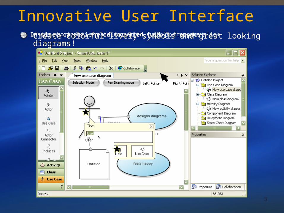
Innovative User InterfaceInnovative User InterfaceCreate colorful lively symbols and great looking diagrams!Create colorful lively symbols and great looking diagrams!In-place convenient editor with full pen supportDesign shorthand, create connected symbols from one click
4
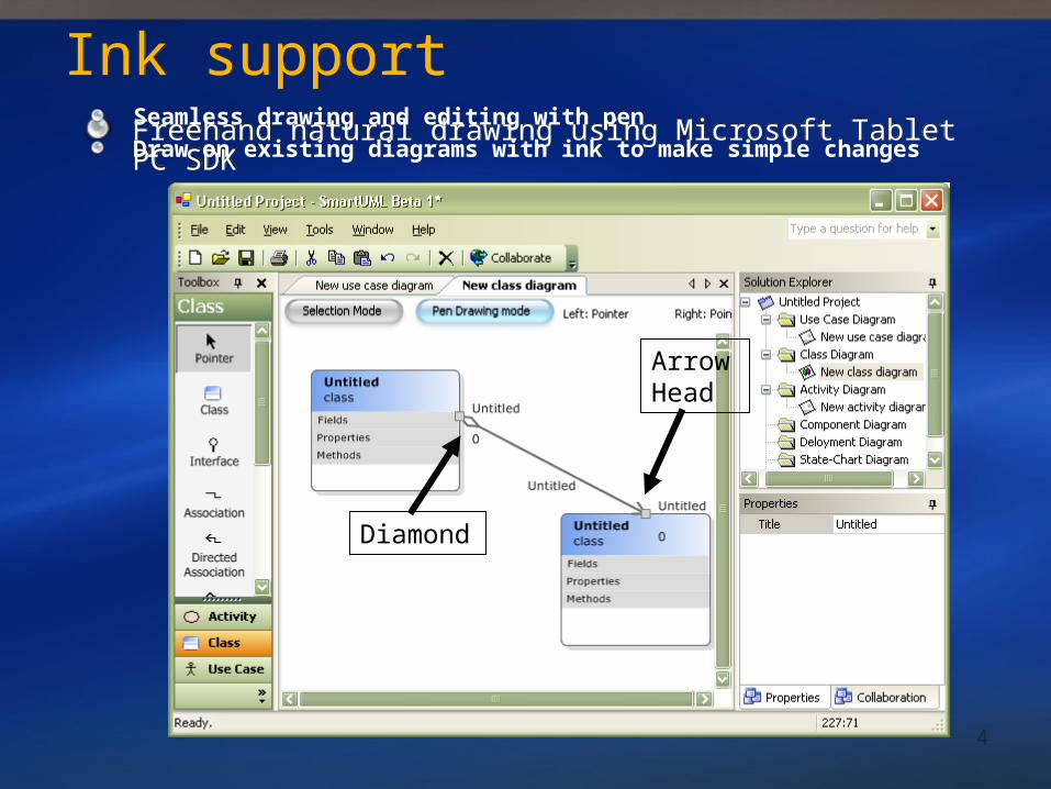
Ink supportInk supportFreehand natural drawing using Microsoft Tablet PC SDKFreehand natural drawing using Microsoft Tablet PC SDKSeamless drawing and editing with penDraw on existing diagrams with ink to make simple changes
Arrow Head
Diamond
5
Enhanced Mouse supportEnhanced Mouse supportDrawing and editing at the same time. Right mouse button
is always the handy pointer. Never select the pointer tool again
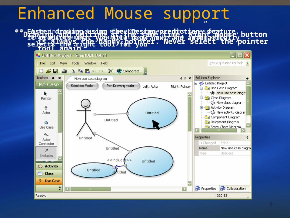
Drawing and editing at the same time. Right mouse button is always the handy pointer. Never select the pointer tool again
Faster drawing using the “Design prediction” feature.It predicts what you will draw next and automatically selects the right tool for you
Auto introduce design elements whenever its necessary. Draw a connector, it automatically adds the right symbol
6
Draw diagrams in a team using the network drawing feature. It’s an electronic whiteboard!
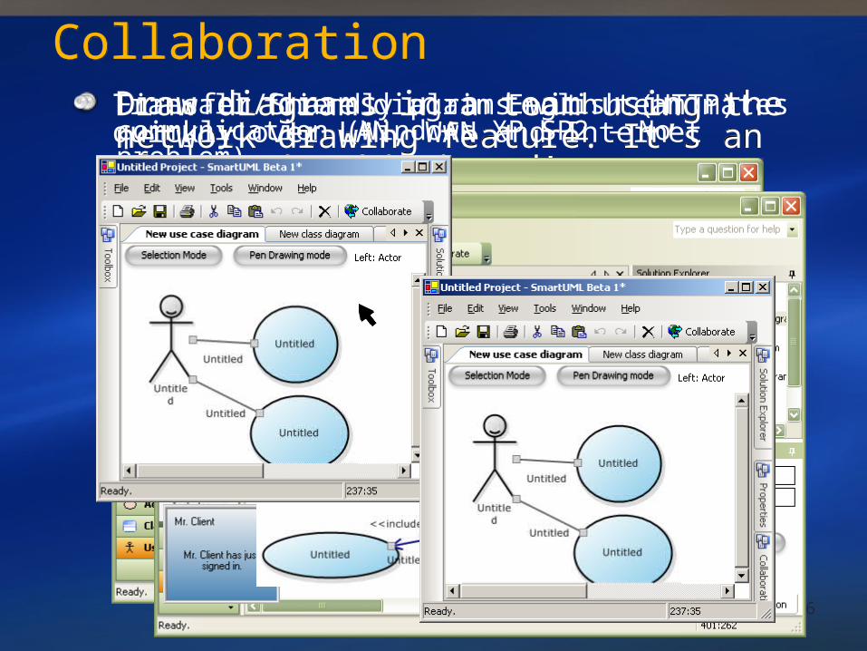
Draw diagrams in a team using the network drawing feature. It’s an electronic whiteboard!
CollaborationCollaborationFirewall friendly plain English (HTTP) communication (Windows XP SP2 - No problem)Transfer/Share diagrams with team mates quickly over LAN, WAN and Internet
7
Sketch Recognition
8
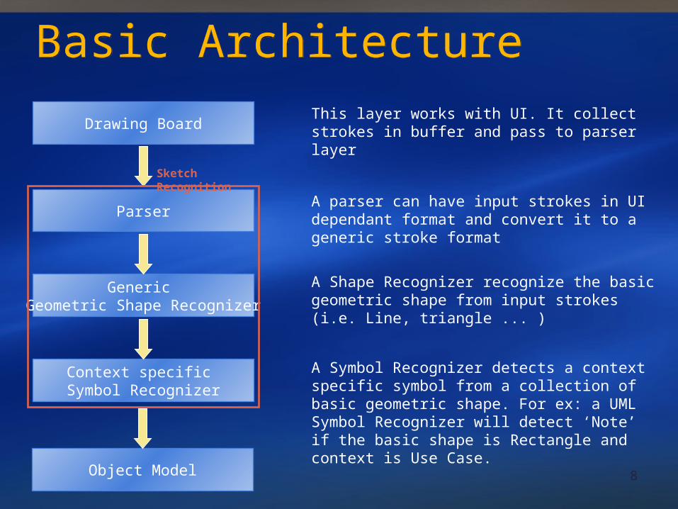
Basic ArchitectureBasic Architecture
Generic Geometric Shape Recognizer
Parser
Context specific Symbol Recognizer
This layer works with UI. It collect strokes in buffer and pass to parser layerDrawing Board
A parser can have input strokes in UI dependant format and convert it to a generic stroke format
A Shape Recognizer recognize the basic geometric shape from input strokes (i.e. Line, triangle ... )
A Symbol Recognizer detects a context specific symbol from a collection of basic geometric shape. For ex: a UML Symbol Recognizer will detect ‘Note’ if the basic shape is Rectangle and context is Use Case.
Object Model
Sketch Recognition

9
Drawing BoardDrawing BoardA drawing board is a place where user can draw freehand diagrams using pen interface.
The drawing board collects the user strokes using Microsoft Table PC ‘s Ink interface. After a certain interval it passes the collected strokes for detection. For use case diagram, it passes the collection when ever a stroke is generated.
10
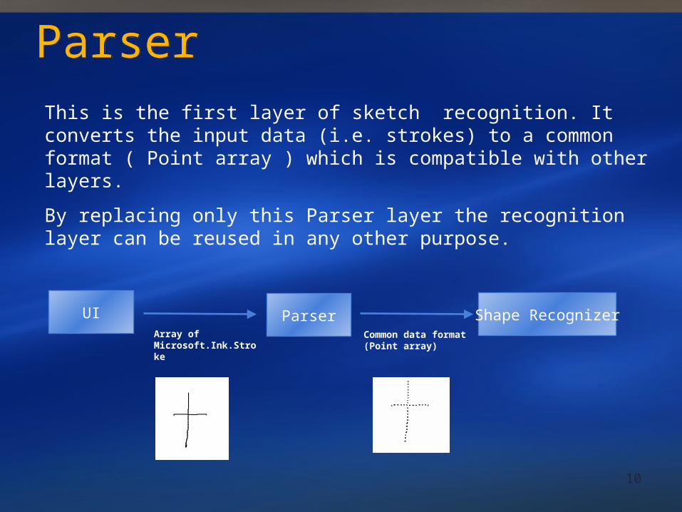
ParserParserThis is the first layer of sketch recognition. It converts the input data (i.e. strokes) to a common format ( Point array ) which is compatible with other layers.
By replacing only this Parser layer the recognition layer can be reused in any other purpose.
Parser Shape RecognizerUIArray of Microsoft.Ink.Stroke
Common data format (Point array)
11
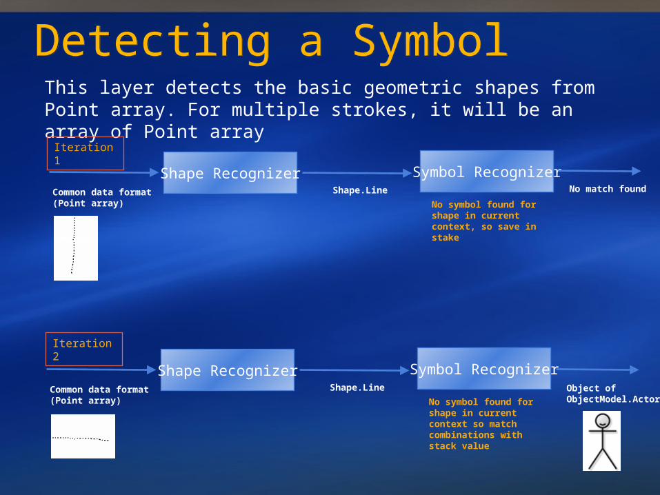
Detecting a SymbolDetecting a SymbolThis layer detects the basic geometric shapes from Point array. For multiple strokes, it will be an array of Point array
Shape RecognizerCommon data format (Point array)
Shape.Line
Symbol Recognizer
No symbol found for shape in current context, so save in stake
Shape RecognizerCommon data format (Point array)
Shape.Line
Symbol Recognizer
No symbol found for shape in current context so match combinations with stack value
Iteration 1
Iteration 2
No match found
Object of ObjectModel.Actor
12
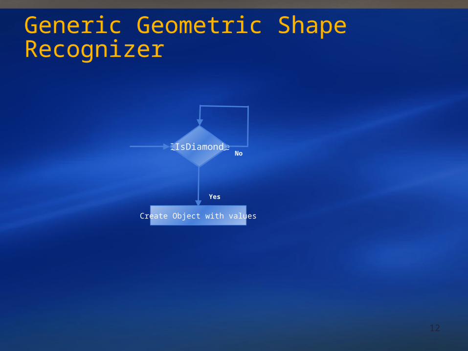
Generic Geometric Shape RecognizerGeneric Geometric Shape Recognizer
IsZigzagNo
IsCircleIsEllipseIsRectangleIsAngleIsLineIsTriangleIsDiamond
Yes
Create Object with values
13
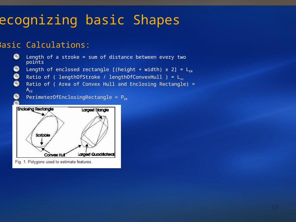
Recognizing basic Shapes
Basic Calculations:Length of a stroke = sum of distance between every two points
Length of enclosed rectangle [(height + width) x 2] = LER
Ratio of ( lengthOfStroke / lengthOfConvexHull ) = Lsc
Ratio of ( Area of Convex Hull and Enclosing Rectangle) = ACE
PerimeterOfEnclosingRectangle = PER
Length of a stroke = sum of distance between every two points
Length of enclosed rectangle [(height + width) x 2] = LER
Ratio of ( lengthOfStroke / lengthOfConvexHull ) = Lsc
Ratio of ( Area of Convex Hull and Enclosing Rectangle) = ACE
PerimeterOfEnclosingRectangle = PER
14
Yes
Yes
.7<Ace<.8
Yes
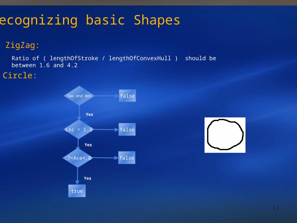
Recognizing basic Shapes
ZigZag:
Ratio of ( lengthOfStroke / lengthOfConvexHull ) should be between 1.6 and 4.2
Circle:
Two end met false
Lsc > 1.3 false
false
true
15Yes
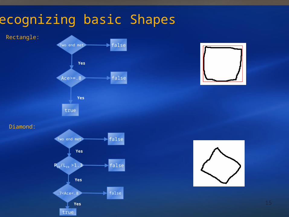
Recognizing basic ShapesRectangle:
Yes
Ace>=.8
Yes
Two end met false
false
true
Diamond:
Yes
PER/LER >1.3
Yes
Two end met false
false
true
.7<Ace<.8 false
16
Yes
false
Yes
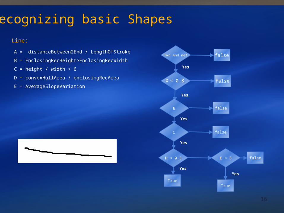
Line:
Yes
X < 0.8
Yes
Two end met false
false
B false
Recognizing basic Shapes
A = distanceBetween2End / LengthOfStroke
B = EnclosingRecHeight>EnclosingRecWidth
C = height / width > 6
D = convexHullArea / enclosingRecArea
E = AverageSlopeVariation
Yes
C false
Yes
D < 0.3 E < 5
TrueTrue
17
XUML Persistence
18
XUML OverviewXUML Overview
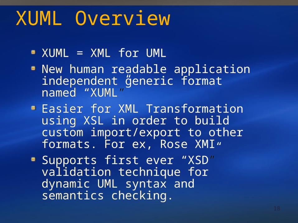
XUML = XML for UMLNew human readable application independent generic format named “XUML”Easier for XML Transformation using XSL in order to build custom import/export to other formats. For ex, Rose XMISupports first ever “XSD” validation technique for dynamic UML syntax and semantics checking.
XUML = XML for UMLNew human readable application independent generic format named “XUML”Easier for XML Transformation using XSL in order to build custom import/export to other formats. For ex, Rose XMISupports first ever “XSD” validation technique for dynamic UML syntax and semantics checking.
19
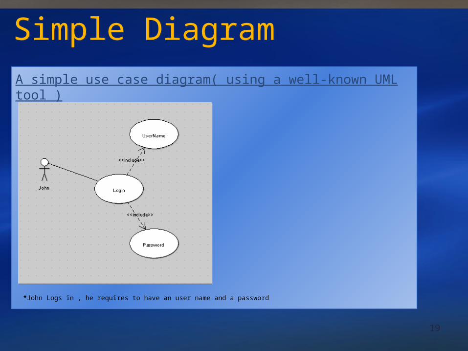
A simple use case diagram( using a well-known UML tool )
Simple DiagramSimple Diagram
*John Logs in , he requires to have an user name and a password

20
XMI – Unreadable, too complexXMI – Unreadable, too complex
Generate tones of unreadable xml
<?xml version="1.0" encoding="UTF-8"?><XMI xmi.version="1.0"> <XMI.header> <XMI.documentation> <XMI.exporter>Novosoft UML Library</XMI.exporter> <XMI.exporterVersion>0.4.20</XMI.exporterVersion> </XMI.documentation> <XMI.metamodel xmi.name="UML" xmi.version="1.3"/> </XMI.header> <XMI.content> <Model_Management.Model xmi.id="xmi.1" xmi.uuid="-84-16-2-12-1e1be92:10122353358:-7ffe"> <Foundation.Core.ModelElement.name>untitledModel</Foundation.Core.ModelElement.name> <Foundation.Core.ModelElement.isSpecification xmi.value="false"/> <Foundation.Core.GeneralizableElement.isRoot xmi.value="false"/> <Foundation.Core.GeneralizableElement.isLeaf xmi.value="false"/> <Foundation.Core.GeneralizableElement.isAbstract xmi.value="false"/> <Foundation.Core.ModelElement.name>Login</Foundation.Core.ModelElement.name> <Foundation.Core.ModelElement.isSpecification xmi.value="false"/> <Foundation.Core.GeneralizableElement.isRoot xmi.value="false"/> <Foundation.Core.GeneralizableElement.isLeaf xmi.value="false"/> <Foundation.Core.GeneralizableElement.isAbstract xmi.value="false"/> <Foundation.Core.ModelElement.namespace> <Foundation.Core.Namespace xmi.idref="xmi.1"/> </Foundation.Core.ModelElement.namespace> //---------- More to Continue------------------------------------------------------
21
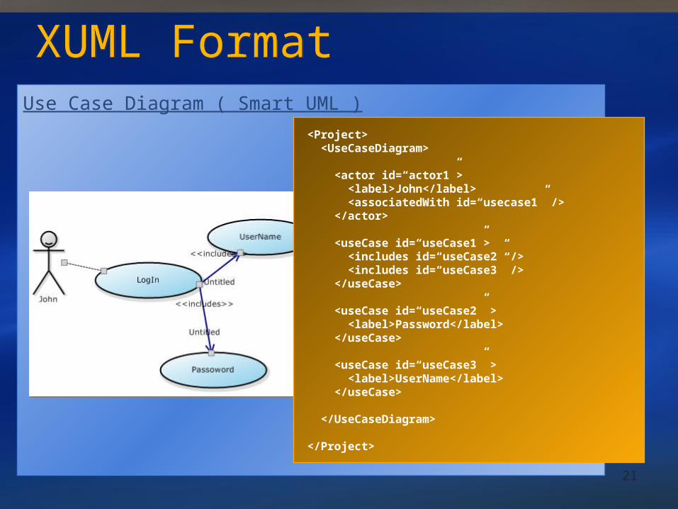
XUML FormatXUML FormatUse Case Diagram ( Smart UML )
<Project> <UseCaseDiagram>
<actor id=“actor1”> <label>John</label> <associatedWith id=“usecase1” /> </actor>
<useCase id=“useCase1”> <includes id=“useCase2” /> <includes id=“useCase3” /> </useCase>
<useCase id=“useCase2” > <label>Password</label> </useCase>
<useCase id=“useCase3” > <label>UserName</label> </useCase>
</UseCaseDiagram>
</Project>
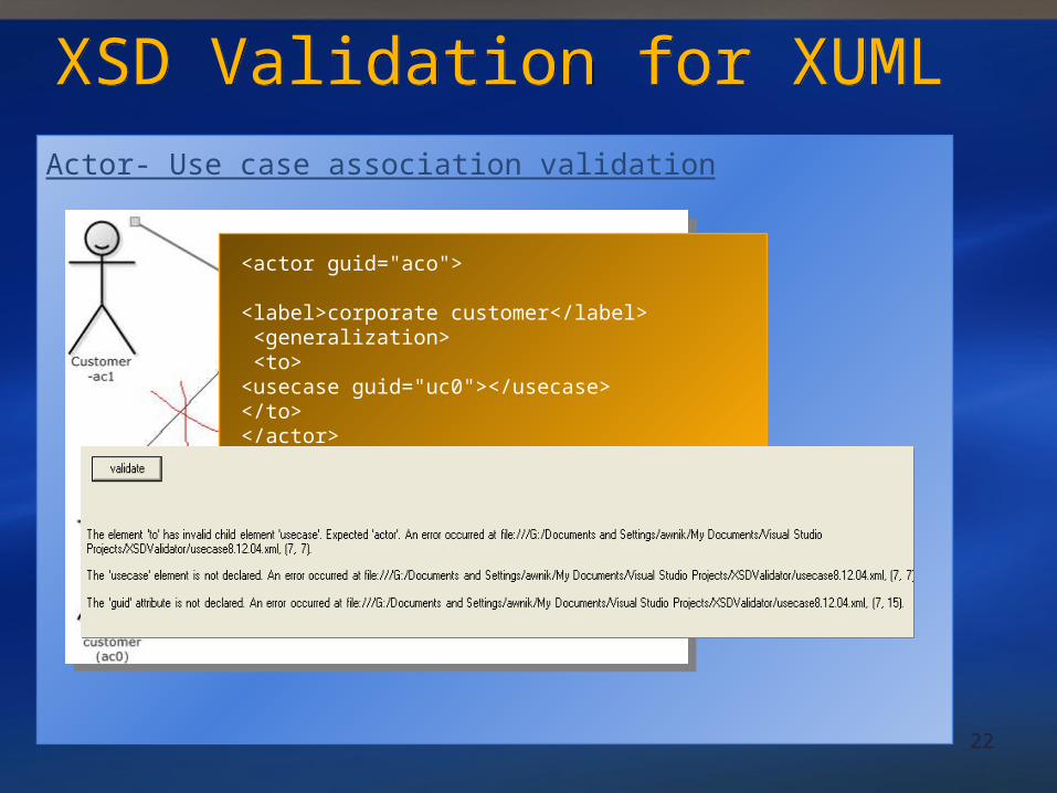
22
XSD Validation for XUMLXSD Validation for XUMLActor- Use case association validation
<actor guid="aco">
<label>corporate customer</label> <generalization> <to><usecase guid="uc0"></usecase> </to></actor>
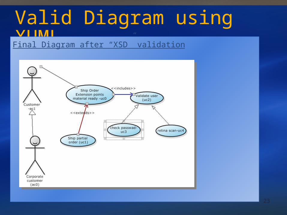
23
Valid Diagram using XUMLValid Diagram using XUMLFinal Diagram after “XSD” validation
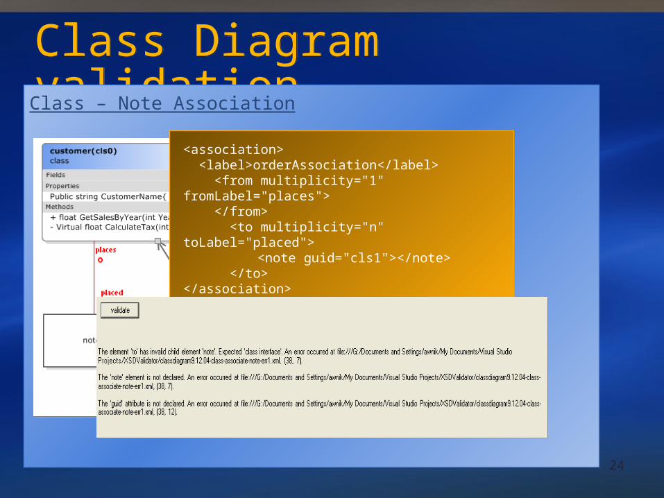
24
Class Diagram validationClass Diagram validationClass – Note Association
<association> <label>orderAssociation</label> <from multiplicity="1" fromLabel="places"> </from> <to multiplicity="n" toLabel="placed">
<note guid="cls1"></note> </to></association>
25
Distributed Command Pattern
26
Distributed Command PatternDistributed Command Pattern
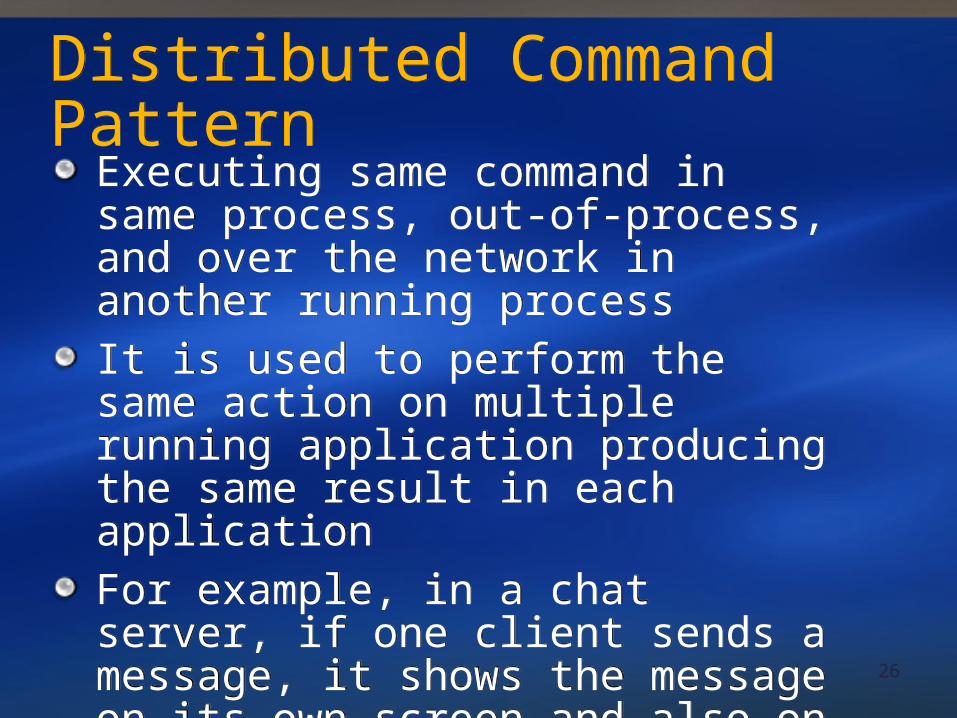
Executing same command in same process, out-of-process, and over the network in another running processIt is used to perform the same action on multiple running application producing the same result in each applicationFor example, in a chat server, if one client sends a message, it shows the message on its own screen and also on all the clients connected to the same server
Executing same command in same process, out-of-process, and over the network in another running processIt is used to perform the same action on multiple running application producing the same result in each applicationFor example, in a chat server, if one client sends a message, it shows the message on its own screen and also on all the clients connected to the same server
27
Overview of Command PatternOverview of Command Pattern
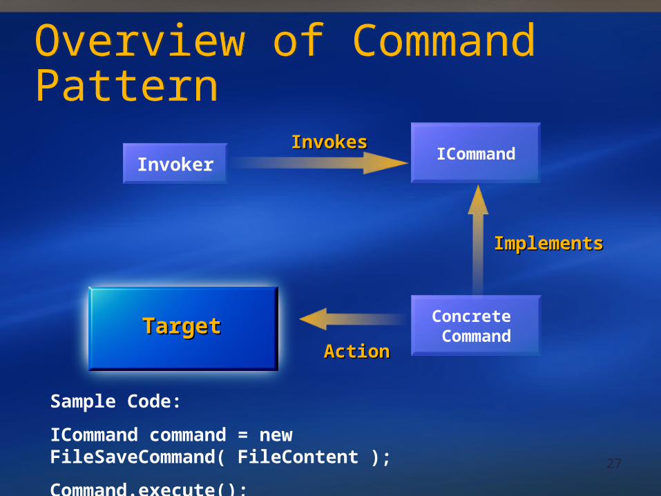
InvokerICommand
InvokesInvokes
Concrete Command
ImplementsImplements
TargetTargetActionAction
Sample Code:
ICommand command = new FileSaveCommand( FileContent );
Command.execute();
28
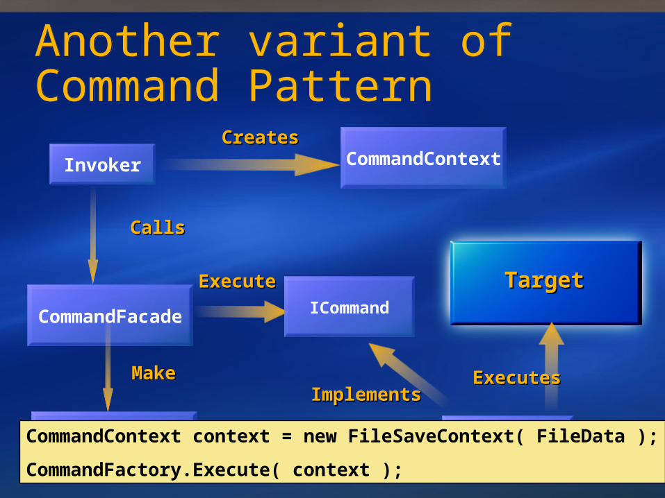
Another variant of Command PatternAnother variant of Command Pattern
Invoker
TargetTarget
ExecutesExecutes
CreatesCreatesCommandContext
CallsCalls
CommandFacade
ExecuteExecute
MakeMake
CommandFactory
ICommand
Concrete Command
ImplementsImplements
InstantiateInstantiateCommandContext context = new FileSaveContext( FileData );
CommandFactory.Execute( context );
29
Distributed Command PatternDistributed Command Pattern
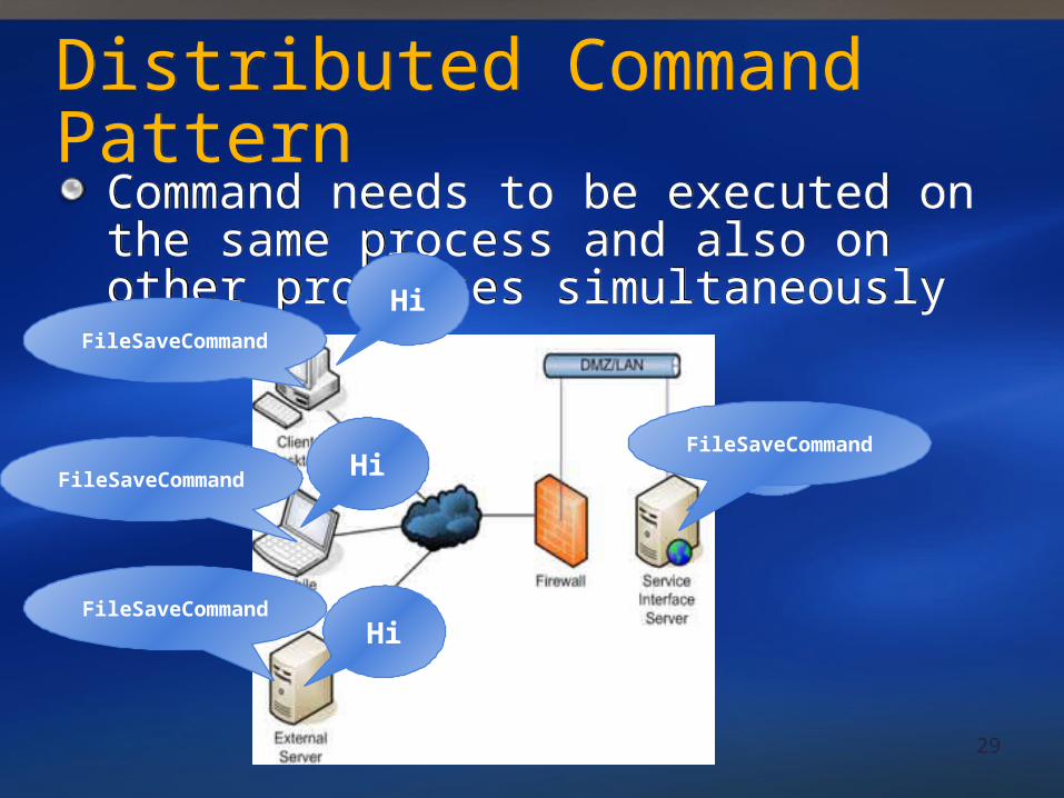
Command needs to be executed on the same process and also on other processes simultaneously
Command needs to be executed on the same process and also on other processes simultaneouslyHi
Hi
Hi
Hi
FileSaveCommand
FileSaveCommand
FileSaveCommand
FileSaveCommand
30
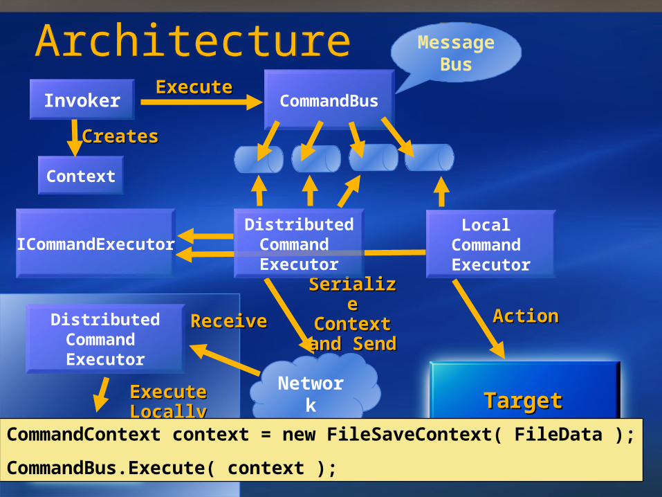
ReceiveReceiveDistributedCommand Executor
ArchitectureArchitectureInvoker CommandBus
ExecuteExecute
Message Bus
ICommandExecutor
TargetTarget
ActionAction
Context
CreatesCreates
Network
Serialize Serialize Context Context
and Sendand Send
Execute Execute LocallyLocally
TargetTarget
DistributedCommand Executor
Local Command Executor
CommandContext context = new FileSaveContext( FileData );
CommandBus.Execute( context );
31
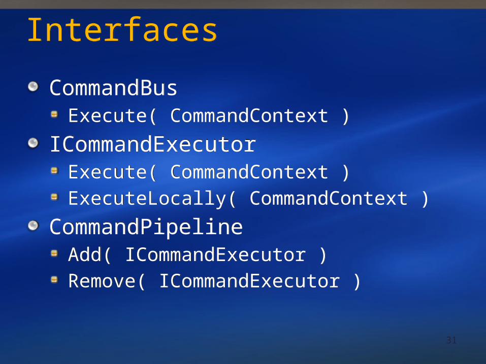
InterfacesInterfaces
CommandBusExecute( CommandContext )
ICommandExecutorExecute( CommandContext )ExecuteLocally( CommandContext )
CommandPipelineAdd( ICommandExecutor )Remove( ICommandExecutor )
CommandBusExecute( CommandContext )
ICommandExecutorExecute( CommandContext )ExecuteLocally( CommandContext )
CommandPipelineAdd( ICommandExecutor )Remove( ICommandExecutor )
32
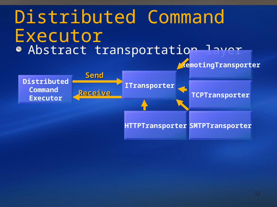
Distributed Command ExecutorDistributed Command Executor
Abstract transportation layerAbstract transportation layer
DistributedCommand Executor
SendSendITransporter
HTTPTransporter
TCPTransporter
SMTPTransporter
RemotingTransporter
ReceiveReceive
33
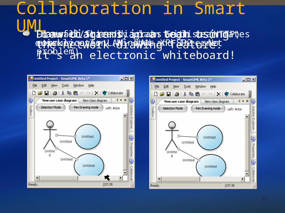
Draw diagrams in a team using the network drawing feature. It’s an electronic whiteboard!
Draw diagrams in a team using the network drawing feature. It’s an electronic whiteboard!
Collaboration in Smart UML
Firewall friendly plain English (HTTP) communication (Windows XP SP2 - No problem)
Transfer/Share diagrams with team mates quickly over LAN, WAN and Internet

34
The End