Architecture Modeling and Processes - WordPress.com · Architecture Modeling and Processes Keeping...
47
input for better outcomes Learn the discipline, pursue the art, and contribute ideas at www.architecturejournal.net 23 UML or DSL: Which Bear Is Best? Modeling in an Agile Context Software Architecture in the Agile Life Cycle Driving Efficiency and Innovation by Consistently Managing Complexity and Change Architecture Modeling and Processes Keeping Architectures Relevant: Using Domain- Driven Design and Emergent Architecture to Manage Complexity and Enable Change Evaluating Application Architecture, Quantitatively Multiple-Context Systems: A New Frontier in Architecture
Transcript of Architecture Modeling and Processes - WordPress.com · Architecture Modeling and Processes Keeping...

input for better outcomes
Learn the discipline, pursue the art, and contribute ideas atwww.architecturejournal.net
23
UML or DSL: Which Bear Is Best?
Modeling in an Agile Context
Software Architecture in the Agile Life Cycle
Driving Efficiency and Innovation by Consistently Managing Complexity and Change
Architecture Modeling and Processes
Keeping Architectures Relevant: Using Domain-Driven Design and Emergent Architecture to Manage Complexity and Enable Change
Evaluating Application Architecture, Quantitatively
Multiple-Context Systems: A New Frontier in Architecture
Contents 23
Foreword 1by Diego Dagum
Keeping Architectures Relevant: Using Domain-Driven Design and Emergent Architecture to Manage Complexity and Enable Change 2by Brandon Satrom and Paul RaynerSound advice on how to keep architecture relevant, and not forgotten, after a solution’s implementation.
Evaluating Application Architecture, Quantitatively 7by V. GnanasekaranAn explanation of ways to confirm that a given approach meets specific criteria before going to the next level.
Software Architecture in the Agile Life Cycle 13by Diego Fontdevila and Martín SalíasA set of techniques and practices for leveraging the agile approach to software architecture.
Driving Efficiency and Innovation by Consistently Managing Complexity and Change 18by Samuel B. (Sam) HolcmanA detailed description of the four pillars of holistic enterprise architecture that will help ensure success.
Multiple-Context Systems: A New Frontier in Architecture 26by Charlie AlfredIdentification and illustration of the implications and trade-offs of adaptable solutions for different deployment contexts.
UML or DSL: Which Bear Is Best? 32by Len Fenster and Brooke HamiltonAn exploration of the pros and cons of both UML and DSLs showing that they can eventually be combined.
Modeling in an Agile Context 38by Alan Cameron WillsAn illustration of how to help the architecture emerge as a consequence of an agile process, instead of a big design upfront.
Sign up for your free subscription to The Architecture Journal www.architecturejournal.net
1The Architecture Journal #23
Foreword
Dear Architect,Exploring our space—partly science, partly art—is always a fascinating and complex task. We could take the contextual approach and address a context-specific subject, as we did recently (BI, SOA, and so on), or we could take the introspective approach of analyzing the role that we play (how we communicate, how we negotiate, and so on). We covered our role two years ago, during the days of Simon Guest as editor. Yet we could take a third approach that is neither context-specific nor introspective, when we review what we produce.
This 23rd issue of The Architecture Journal is on Architecture Modeling and Processes. The articles that were selected for this occasion deal with aspects such as:
• Change-enabled architectures. Brandon Satrom and Paul Rayner advise us on how to keep architecture relevant, and not forgotten, after the solution has been implemented.
• Architecture verification. V. Gnanasekaran explains ways to confirm that a given approach meets specific criteria prior to going to the next level.
• Enterprise architecture. Sam Holcman details the four pillars of success.• Adaptable solutions for different deployment contexts. Charlie Alfred
identifies the implications and trade-offs, with illustrative examples.• Unified Modeling Language (UML) vs. Domain-Specific Languages (DSLs).
Lenny Fenster and Brooke Hamilton dive in to the pros and cons of both alternatives, and show that these can eventually be combined.
• Maturing architectures in agile processes. I wish that I had read articles like Alan Wills’s or Diego Fontdevila and Martín Salías’s before starting my first agile process last decade—when I couldn’t deal with the fact that the next release was in three weeks, and I felt unable to complete my architecture in less than two-and-a-half months.
The latest articles in this issue show specific examples that use the upcoming Microsoft Visual Studio 2010 suite. We are less than a month away from the launch of this Microsoft tool for .NET development, which—since its 2005 version—has been incorporating aspects of application life-cycle management (ALM) that span way beyond developer boundaries to include project managers, testers, user leads, and architects. For these latter stakeholders, the incorporation of UML support plus an extra layer diagram will serve later to avoid improper cross-layer references in code. The newly added Architecture Explorer allows matching architecture components easily with their respective implementation source code. It’s remarkable that our prime development tool has been consistently awarded as the best IDE for several years now.
On that note, I’ll finish my intro by thanking my guest editor-in-chief for this occasion, Peter Provost, Microsoft Sr. Program Manager for Visual Studio 2010 Architect Edition. Peter helped me understand the IDE landscape and its crossovers with the architect’s job, in order to select for you the most relevant information about how much Microsoft addresses those issues in Visual Studio 2010. I must extend the acknowledgement to the editorial board that helped Peter and me review the papers during the authoring phases.
We hope that you enjoy this issue. Don’t forget to review the 10-minute videos that we’ve made as companion material. As usual, you can send us your comments at [email protected].
FounderArvindra Sehmi
DirectorCyra Richardson
Editor-in-ChiefDiego Dagum , Peter Provost (Guest editor)
Editorial BoardDavid Throwbridge, Nidhish Dhru, Mike Cramer, Lalo Steinmann, Gustavo Gattass Ayub, Denny Dayton, Eliaz Tobias
Editorial and Production Services WASSER StudiosDionne Malatesta, Program ManagerIsmael Marrero, EditorDennis Thompson, Design DirectorCover image, ©iStockphoto.com/Alex Slobodkin
®
The information contained in The Architecture Journal (“Journal”) is for information purposes only. The material in the Journal does not constitute the opinion of Microsoft Corporation (“Microsoft”) or Microsoft’s advice and you should not rely on any material in this Journal without seeking independent advice. Microsoft does not make any warranty or representation as to the accuracy or fitness for purpose of any material in this Journal and in no event does Microsoft accept liability of any description, including liability for negligence (except for personal injury or death), for any damages or losses (including, without limitation, loss of business, revenue, profits, or consequential loss) whatsoever resulting from use of this Journal. The Journal may contain technical inaccuracies and typographical errors. The Journal may be updated from time to time and may at times be out of date. Microsoft accepts no responsibility for keeping the information in this Journal up to date or liability for any failure to do so. This Journal contains material submitted and created by third parties. To the maximum extent permitted by applicable law, Microsoft excludes all liability for any illegality arising from or error, omission or inaccuracy in this Journal and Microsoft takes no responsibility for such third party material.
A list of Microsoft Corporation trademarks can be found at http://www.microsoft.com/library/toolbar/3.0/trademarks /en-us.mspx. Other trademarks or trade names mentioned herein are the property of their respective owners.
All copyright and other intellectual property rights in the material contained in the Journal belong, or are licensed to, Microsoft Corporation. You may not copy, reproduce, transmit, store, adapt or modify the layout or content of this Journal without the prior written consent of Microsoft Corporation and the individual authors.
Copyright © 2010 Microsoft Corporation. All rights reserved.
Diego DagumEditor-in-Chief
2 The Architecture Journal 23
Summary
Sustainable and successful software development is all about managing complexity and enabling change. Successful software architects create designs that clearly address both concerns. For businesses that have complex domains, designing with evolution in mind and using techniques from Domain-Driven Design will result in systems whose architectures deliver a strong, sustainable competitive advantage.
IntroductionToo many systems become legacy upon release, while some never have a chance to move into production before they are undermined by the calcification of unmet expectations and mismatched domain needs. Regardless of the design effort early in the life cycle, neglecting the domain model and producing inflexible design results in the increasing irrelevance of the architecture of a system. The accidental complexity of that system rises, and communication between developers and customers deteriorates. Changes and new features become more difficult to accommodate, as the richness and value of the system’s essential complexity is eroded. Sustainable and successful software development is all about managing complexity and enabling change. Successful architects create designs that address both.
Architects, domain experts, and developers collaborate to mitigate complexity through strategic modeling and design. This requires a focus on the core business domain and the continuous application of appropriate design patterns. Ongoing effort should be expended on defining and refining the domain model through the establishment and exercise of a language that everyone shares. The development of this Ubiquitous Language, along with the use of Domain-Driven Design techniques, enables business problems and their solutions to be expressed through rich domain models that are both meaningful to business experts and executable by the development team.
Keeping our architectures relevant also means enabling change. As architecture is allowed to emerge, evolve, and mature, it becomes a true reflection of the deep understanding of both domain experts and developers. Combining a strong domain-model focus with continuous attention to growing the software architecture can be a potent way to enable change while managing complexity. This does not guarantee success; still, architects who distill the business domain into a rich model, incorporate it deeply into the system, and design with evolution in mind are on the path to creating architectures that can deliver a strong, sustainable competitive advantage to the business.
Ubiquitous LanguageThe (Hidden) Cost of TranslationAccording to Eric Evans, Ubiquitous Language is “...a language structured around the domain model and used by all team members to connect all the activities of the team with the software.”1 Ubiquitous Language should drive every piece of communication between a development team and the business domain—from spoken and written communication to models, system documentation, automated tests, diagrams, and the code itself. Nothing should be allowed to bypass the requirement that the shared and codified language of the domain permeate through all aspects of a software project.
Consider the following conversation between a domain expert and a development team:
Expert: We need to make sure that our support staff can change the rules that we use to create policies for customers.
Architect: Okay, so, we’ll use a strategy pattern and make that config-driven...
Developer: We could just use IoC, build strategies for each implementation, and let the users swap out implementations whenever they need to change them.
Architect: That’s an option, too. We’ll figure it out offline.Expert: (confused) So, will the support staff be able to change those?Architect: Sure. They’ll change config, and it’ll just work.Developer: Or swap out an implementation for the container
in config.Expert: What’s IoC?Architect: Well...
Now, consider the following alternate take on the same conversation:
Expert: We need to make sure that our support staff can change the rules that we use to create policies for customers.
Architect: Okay, so, the POLICY BUILDER will need to be able to support the addition and/or replacement of POLICY RULES by a POLICY ANALYST?
Expert: Yeah, exactly. We call it the Policy Wizard, but I like your term better.
Architect: Can we agree to globally replace Policy Wizard with POLICY BUILDER in all of our discussions and usage? We want to make sure that everyone understands these terms and uses them consistently.
Expert: Sure. If you can help me write up an e-mail, we can inform people of the change today.
Developer: So, what kinds of things do POLICY ANALYSTS change in a POLICY RULE?
Expert: Effective dates, amount limits—minor details, really.
Keeping Architectures Relevant: Using Domain-Driven Design and Emergent Architecture to Manage Complexity and Enable Changeby Brandon Satrom and Paul Rayner
3
Keeping Architectures Relevant: Using Domain-Driven Design and Emergent Architecture to Manage Complexity and Enable Change
The Architecture Journal 23
Developer: So, only attributes about the policy. Is there any swapping in and out of policies?
Expert: No. We don’t do that often. When we do, it requires executive approval and process changes.
Architect: Okay, so, POLICY RULE changes performed by a POLICY ANALYST will be minor; otherwise, we’ll need to perform system changes as a part of those process changes.
Expert: That makes sense.
In the first conversation, the architect and developer muddled the dialogue with the domain expert by introducing technical detail that was essentially irrelevant to the business domain. If a strategy pattern is to be used to solve a business problem, it is important to discuss how such a pattern should be implemented in one’s framework of choice. However, it is not useful to do so in a conversation that is designed to scope the domain and the software that is being created to add value to that domain. In the first example, the architect and developer spent far too little time understanding the expert’s domain. The mention of rules and runtime modifications of the system resulted in an immediate jump to patterns and framework details.
On the other hand, the business domain is also not well-served if the developer and architect sit idly by and allow the domain expert to define all project knowledge in terms of the business. Business domains typically suffer from inconsistencies and ambiguities that experts either are not aware of or allow to exist for various reasons. The jargon that invariably grows around a business domain is usually a mix of well-defined terminology, inexact analogies, muddled and overlapping ideas, and contentious concepts that never reach resolution. Whereas the technical jargon is precise but mostly irrelevant to the business domain, the business domain is imprecise and lacks the stability that a model and software require to be successful.
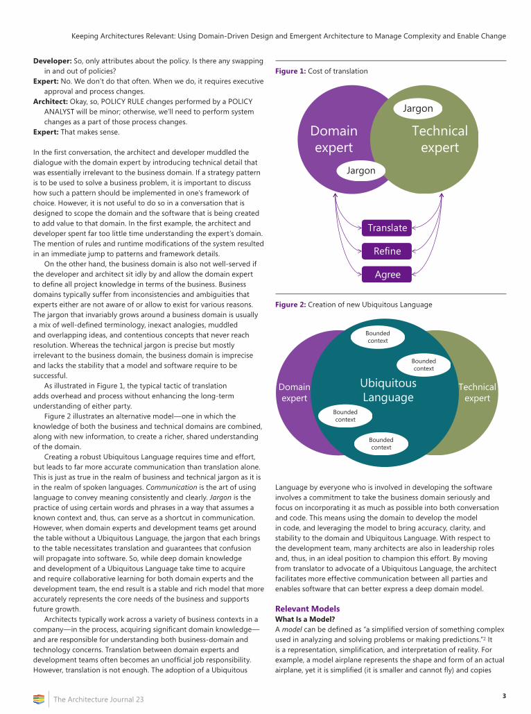
As illustrated in Figure 1, the typical tactic of translation adds overhead and process without enhancing the long-term understanding of either party.
Figure 2 illustrates an alternative model—one in which the knowledge of both the business and technical domains are combined, along with new information, to create a richer, shared understanding of the domain.
Creating a robust Ubiquitous Language requires time and effort, but leads to far more accurate communication than translation alone. This is just as true in the realm of business and technical jargon as it is in the realm of spoken languages. Communication is the art of using language to convey meaning consistently and clearly. Jargon is the practice of using certain words and phrases in a way that assumes a known context and, thus, can serve as a shortcut in communication. However, when domain experts and development teams get around the table without a Ubiquitous Language, the jargon that each brings to the table necessitates translation and guarantees that confusion will propagate into software. So, while deep domain knowledge and development of a Ubiquitous Language take time to acquire and require collaborative learning for both domain experts and the development team, the end result is a stable and rich model that more accurately represents the core needs of the business and supports future growth.
Architects typically work across a variety of business contexts in a company—in the process, acquiring significant domain knowledge—and are responsible for understanding both business-domain and technology concerns. Translation between domain experts and development teams often becomes an unofficial job responsibility. However, translation is not enough. The adoption of a Ubiquitous
Language by everyone who is involved in developing the software involves a commitment to take the business domain seriously and focus on incorporating it as much as possible into both conversation and code. This means using the domain to develop the model in code, and leveraging the model to bring accuracy, clarity, and stability to the domain and Ubiquitous Language. With respect to the development team, many architects are also in leadership roles and, thus, in an ideal position to champion this effort. By moving from translator to advocate of a Ubiquitous Language, the architect facilitates more effective communication between all parties and enables software that can better express a deep domain model.
Relevant ModelsWhat Is a Model?A model can be defined as “a simplified version of something complex used in analyzing and solving problems or making predictions.”2 It is a representation, simplification, and interpretation of reality. For example, a model airplane represents the shape and form of an actual airplane, yet it is simplified (it is smaller and cannot fly) and copies
Figure 1: Cost of translation
Jargon
Domainexpert
Technicalexpert
Jargon
Translate
Refine
Agree
Figure 2: Creation of new Ubiquitous Language
Domainexpert
Technicalexpert
UbiquitousLanguage
Boundedcontext
Boundedcontext
Boundedcontext
Boundedcontext
Keeping Architectures Relevant: Using Domain-Driven Design and Emergent Architecture to Manage Complexity and Enable Change
The Architecture Journal 234
only those aspects of the original that the designer found important to imitate (it has doors and wheels, but no engine or complex machinery).
Beyond being a simplified representation of a thing, a model must have a purpose—that of “solving problems or making predictions.”3 When it is used for scientific or engineering purposes, a model exists to enable the model-makers to express something nebulous and complex in a manner that can be understood, communicated, and manipulated. Thus, a model, while simplified, must remain meaningfully connected to the thing that it represents in order to be useful in solving problems.
A domain model is no different. It is a widely accepted fact in software that domain models are intended to represent a business domain or “problem space.” What seems to be less accepted is the idea that these models first and foremost must express the business domain clearly, and not be an expression of technical jargon or framework limitations. The establishment of a Ubiquitous Language enables emphasis of a domain model that represents the domain accurately and deeply, instead of one that is filled with inexact terminology or obfuscating technical detail.
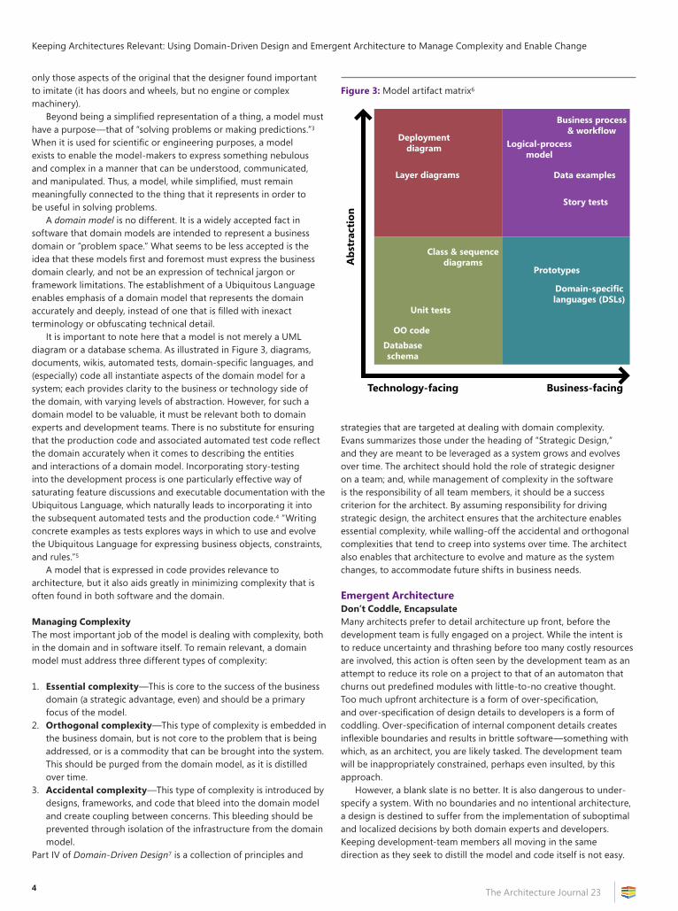
It is important to note here that a model is not merely a UML diagram or a database schema. As illustrated in Figure 3, diagrams, documents, wikis, automated tests, domain-specific languages, and (especially) code all instantiate aspects of the domain model for a system; each provides clarity to the business or technology side of the domain, with varying levels of abstraction. However, for such a domain model to be valuable, it must be relevant both to domain experts and development teams. There is no substitute for ensuring that the production code and associated automated test code reflect the domain accurately when it comes to describing the entities and interactions of a domain model. Incorporating story-testing into the development process is one particularly effective way of saturating feature discussions and executable documentation with the Ubiquitous Language, which naturally leads to incorporating it into the subsequent automated tests and the production code.4 “Writing concrete examples as tests explores ways in which to use and evolve the Ubiquitous Language for expressing business objects, constraints, and rules.”5
A model that is expressed in code provides relevance to architecture, but it also aids greatly in minimizing complexity that is often found in both software and the domain.
Managing ComplexityThe most important job of the model is dealing with complexity, both in the domain and in software itself. To remain relevant, a domain model must address three different types of complexity:
1. Essential complexity—This is core to the success of the business domain (a strategic advantage, even) and should be a primary focus of the model.
2. Orthogonal complexity—This type of complexity is embedded in the business domain, but is not core to the problem that is being addressed, or is a commodity that can be brought into the system. This should be purged from the domain model, as it is distilled over time.
3. Accidental complexity—This type of complexity is introduced by designs, frameworks, and code that bleed into the domain model and create coupling between concerns. This bleeding should be prevented through isolation of the infrastructure from the domain model.
Part IV of Domain-Driven Design7 is a collection of principles and
strategies that are targeted at dealing with domain complexity. Evans summarizes those under the heading of “Strategic Design,” and they are meant to be leveraged as a system grows and evolves over time. The architect should hold the role of strategic designer on a team; and, while management of complexity in the software is the responsibility of all team members, it should be a success criterion for the architect. By assuming responsibility for driving strategic design, the architect ensures that the architecture enables essential complexity, while walling-off the accidental and orthogonal complexities that tend to creep into systems over time. The architect also enables that architecture to evolve and mature as the system changes, to accommodate future shifts in business needs.
Emergent ArchitectureDon’t Coddle, EncapsulateMany architects prefer to detail architecture up front, before the development team is fully engaged on a project. While the intent is to reduce uncertainty and thrashing before too many costly resources are involved, this action is often seen by the development team as an attempt to reduce its role on a project to that of an automaton that churns out predefined modules with little-to-no creative thought. Too much upfront architecture is a form of over-specification, and over-specification of design details to developers is a form of coddling. Over-specification of internal component details creates inflexible boundaries and results in brittle software—something with which, as an architect, you are likely tasked. The development team will be inappropriately constrained, perhaps even insulted, by this approach.
However, a blank slate is no better. It is also dangerous to under-specify a system. With no boundaries and no intentional architecture, a design is destined to suffer from the implementation of suboptimal and localized decisions by both domain experts and developers. Keeping development-team members all moving in the same direction as they seek to distill the model and code itself is not easy.
Figure 3: Model artifact matrix6
Technology-facing Business-facing
Abs
trac
tion
Business process& workflow
Logical-processmodel
Data examples
Story tests
Prototypes
Domain-specificlanguages (DSLs)
Class & sequencediagrams
Unit tests
OO codeDatabaseschema
Deploymentdiagram
Layer diagrams
5
Keeping Architectures Relevant: Using Domain-Driven Design and Emergent Architecture to Manage Complexity and Enable Change
The Architecture Journal 23
One way to connect the domain model to business drivers and ensure that the team is aware of the value of what it is delivering is for the architect to lead in the creation and communication of a domain-vision statement that elucidates the core domain and its value.8
The balance between over- and under-specification can be achieved through engagement and encapsulation. Architects should spend at least part of their time as active members of a development team—not only creating architecture models, diagrams, and deliverables, but also writing code, as the code is the design.9 An architect should be involved in the development of the model through conversation, modeling, documentation, prototyping, and coding.10 By being actively engaged with a development team, the architect is less likely to make decisions that would be perceived as coddling. Architects will not only learn to value accurately the contributions of the rest of the development team, but will also be forced to keep their skills current, live with their own dictates, and avoid over-constraining themselves or the team.
Where constraints are needed, an architect should use encapsulation as a guide for specification. Simply put, architects should focus their efforts in the domain by clearly defining what a given capability provides, and not how that capability should be implemented down to the precise details. The architect should collaborate with the development team to define and code higher-level contexts, responsibilities, interfaces, and interactions, as needed, and leave the details to the team. The development team, through the rigorous use of automated unit and story tests via continuous integration, is then able to improve the system design incrementally and continually—both within and across model-context boundaries—without compromising system functionality. Gartner uses the term “Emergent Architecture” to describe this practice.11
When you use architectural specifications and models as a replacement for engagement with a development team, you are coddling. On the other hand, when you are focused on creating a loose boundary that exposes domain knowledge, you are encapsulating. Focusing on the latter allows the architecture to emerge, evolve, and—more importantly to the architect—remain relevant to both the domain and the development team.
Design with Evolution in Mind“Design for change” is a mantra that we have often heard as architects and developers; but, what does it mean? When a team assumes that it must design for everything to change, it quickly finds itself in a death spiral of over-engineering that is based on speculative requirements, instead of actual ones. In reality, design for change requires managing dependencies carefully by ordering and isolating cohesive areas of the system from each other. For the architect, designing for change implies selecting an architecture or design that complements this ordering and isolation.
Layered architectures are typically employed to achieve the kind of ordering and isolation that is described here, but they often violate the Dependency Inversion Principle and, thus, enable—if not encourage—the kind of accidental coupling that works against the original purpose. As an alternative, consider the “Onion Architecture” approach.12 Originally described by Jeffrey Palermo, the “Onion Architecture” approach focuses on isolating layers through interfaces; leveraging inversion of control to minimize coupling; and, more importantly, making the domain model the star of the show.
For Domain-Driven Design and Emergent Architecture to be truly effective partners, the domain model should be both core to the application and isolated as much as possible from all concerns that are not relevant to the business domain. In practical terms, this means
that orthogonal concerns such as logging, security, and persistence should be implemented elsewhere—leaving the domain free to do what it does best: express the fundamental value of a business application through clean models that are accessible to developers and domain experts alike.
When you have achieved this kind of isolation, you have a structure that enables independent layers to evolve and change at different rates, and with little friction between and internal to those layers. The domain model can then be distilled as deeper insights into the domain become apparent and, thus, can evolve even as infrastructure concerns such as data access are implemented and tested. This applies to more than just vertical layering, as the architect can also provide strategic value by explicitly defining a context for each model and maintaining model integrity within and across bounded contexts.13 The architect should also help articulate the value of core domain distillation to stakeholders.
In some ways, the kind of independence that is described here is exactly what the phrase “architect the lines, not the boxes” is intended to convey. By leveraging clean interfaces, inversion of control, and a rich domain model, architects can maximize their value to the domain and development teams by delivering an architecture that is flexible and change-absorbent without being too prescriptive.
ConclusionTo remain valued and valuable, the architecture of a system must be relevant—that is, intimately connected to both the core business domain and the development team. An architect can establish this relevance by advocating the development of a Ubiquitous Language—eliminating the need for translation, and fostering collaboration between domain experts and developers. That relevance will grow as the domain model is established as core to the software effort, is refined over time to express the core business domain deeply, and remains free from orthogonal concerns. Finally, the architect solidifies relevance by creating an architecture that emerges and evolves with the deeper understanding of domain experts and developers.
All of these steps require an architect who is deeply engaged with the development team and fully invested in the success of the software solution. A commitment to the principles, patterns, and practices of Domain-Driven Design and Emergent Architecture can provide the simplest yet most powerful result of all: software that solves a core business problem, adapts to new business needs, and continues to delight users for years to come.
AcknowledgementsThank you to Eoin Woods, Vaughn Vernon, Jeffrey Palermo, and Dan Haywood for providing valuable feedback on the draft manuscript.
References1 Evans, Eric. Domain-Driven Design: Tackling Complexity in
the Heart of Software. Boston, MA: Addison-Wesley, 2004. (For more resources on domain-driven design, see http://bit.ly/ddd_resources.)
2 Microsoft Corporation. “Model” (definition). Encarta World English Dictionary, 2009.
3 Ibid.4 For more on story tests, see http://bit.ly/storytesting.5 Mugridge, Rick, and Ward Cunningham. Fit for Developing
Software: Framework for Integrated Tests. Upper Saddle River, NJ: Prentice Hall PTR, 2005; 336.
Keeping Architectures Relevant: Using Domain-Driven Design and Emergent Architecture to Manage Complexity and Enable Change
The Architecture Journal 236
6 Adapted from “Agile Testing Matrix,” by Brian Marick, in Implementing Lean Software Development: From Concept to Cash, by Mary Poppendieck and Thomas D. Poppendieck (Upper Saddle River, NJ: Addison-Wesley, 2007), 199.
7 Evans, 327.8 Evans, 415.9 Jack Reeves’s seminal article “What Is Software Design?” is
available at http://www.developerdotstar.com/mag/articles/reeves_design_main.html.
10 See Grady Booch’s comments at http://www.informit.com/articles/article.aspx?p=1405569.
11 http://www.gartner.com/it/page.jsp?id=1124112.12 http://jeffreypalermo.com/blog/the-onion-architecture-part-1/.
Alistair Cockburn’s idea of hexagonal architecture (http://alistair.cockburn.us/Hexagonal+architecture) is similar and predates Palermo’s work.
13 Evans, 335 and 344.
About the AuthorsBrandon Satrom is the Chief Architect with Thought Ascent, Inc., a Microsoft Gold Partner. He blogs at www.userinexperience.com and can be reached at [email protected].
Paul Rayner is a Solutions Architect and Principal for Virtual Genius, LLC. He blogs at www.virtual-genius.com/blog and can be reached at [email protected].
Spiral Architecture Driven Developmentby Andrey Pererva
The main idea of Spiral Architecture Driven Development (SADD) is to produce a system architecture to cope with architectural and technological risks in the early iterations of the project life cycle. SADD is based on the spiral-development model of Boehm and uses the best practices of RUP, Iconix, AGILE, and PMBOK:
• Develop iteratively.• Produce the executable architectural prototypes to mitigate
risks that are related to nonfunctional requirements, such as performance, reliability, and throughput.
• Produce the architectural prototypes that gradually evolve to become the final system in the later iterations.
Let us take a glance at the iterations of SADD.
Conception CreationThe purpose of this iteration is to create a system conception.
Quality attributes are identified, and architecturally significant stakeholder requests are analyzed for their use as the basis of system-architecture conception. The architectural prototype is validated to satisfy quality attributes, particular performance, and loading.
The result of this iteration is that an executable architectural prototype implements the basic use-case flows.
Architecture DesignThe purpose of this iteration is to develop a system architecture.
The technological and quality-attribute achievement risks are identified, and a risk-mitigation plan is created.
Architecturally significant stakeholder requests are analyzed to identify new assumptions that have an effect on the system-architecture design.
The result of this iteration is that an executable architectural prototype implements 20 to 30 percent of alternative use-case flows.
ImplementationThe purpose of this iteration is to implement the functionality of the system.
The risks that are related to satisfying system functions and user requirements are identified and mitigated in a new version of the architectural prototype. All assumptions and constraints are analyzed. Functional testing and integration testing are performed.
The result of this iteration is that an executable architectural prototype implements 40 to 60 percent of alternative use-case flows.
ProductionThe purpose of this iteration is to stabilize code.
The deployment requirements are developed and met during this iteration. The system is validated by tests.
This iteration is intended to plan the development of the next version of the system, create system requirements and architecture specifications, and prepare the system for deployment. The Statement of Work for the next version of the system is created.
The result of this iteration is a fully functional and documented version of the system.
For a detailed description of SADD, please go to http://sadd.codeplex.com.
Andrey Pererva ([email protected]) is the Head of business automation and information program at 360D Interactive Agency.
7The Architecture Journal 23
Summary
This article describes how quantitative treatment can be applied to an application’s architecture-evaluation process and shows how a quantitative output with intuitive reports will provide more clarity than a qualitative output on the quality of an application architecture.
“You cannot control what you cannot measure.” —BILL HEWITT
IntroductionEvaluation of an application architecture is an important step in any architecture-definition process. Its level of significance varies from organization to organization, based on a variety of factors (such as application size and business criticality). In some IT organizations, it is a part of a formal process; in others, it is performed only upon special requests that stakeholders might raise. Enterprises sometimes have a dedicated “Architectural Review Board” (or ARB) that is made up of a team of experienced architects who are earmarked for performing periodic architectural evaluations.
Scenarios that drive the architecture-evaluation process include:
• When a business must validate an application architecture to see whether it can support new business models.
• An expansion to new geographies and regions—resulting in the need to check whether an existing application architecture can scale to new levels.
• Impaired application performance and user concerns that lead to an assessment, to see whether it can be reengineered with minimal effort to ensure optimum performance.
• Stakeholders having to ensure that a proposed application architecture will meet all technical and business goals—ensuring that key architectural decisions were made with key use cases/architectural scenarios in mind and will meet the nonfunctional requirements of the application.
In the context of the new application development, the key objectives of carrying out an architecture-evaluation process are:
• Avoiding costly redevelopment later in the software-development life-cycle (SDLC) process by detecting and correcting architectural flaws earlier.
• Eliminating surprises and last-minute rework that is due to the suboptimal usage of technology options that are provided by platform vendors such as Microsoft.
Architectural reviews are also performed based on only a particular quality-of-service attribute—such as “Performance” or “Security”—for example, how secure the architecture is, whether an architecture has the potential to support a certain number of transactions per second, or whether an architecture will support such a specified time.
The application architectural-evaluation process involves a preliminary review, based on a checklist that is provided by the platform vendor and subsequent presentations, debates, brainstorming sessions, and whiteboard discussions among the architects. Key aspects of brainstorming sessions also include the outputs of the scenario-based evaluation exercises that are performed by using industry-standard methods such as the Architecture Trade-Off Analysis Method (ATAM), Software Architecture Analysis Method (SAAM), and Architecture Reviews for Intermediate Designs (ARID). There are also different methods that are available in the industry to assess the architectures, based exclusively on factors such as cost, modifiability, and interoperability.
The checklist that is provided by a platform vendor ensures the adoption of the right architectural patterns and appropriate design patterns. With its patterns & practices initiative, Microsoft provides a set of checklists/questionnaires across various crosscutting concerns for the evaluation of application architectures that are built on Microsoft’s platform and products. An architecture-evaluation process usually results in an evaluation report that contains qualitative statements such as, “The application has too many layers” or “The application cannot be scaled out, because the layers are tightly coupled.”
Instead of having qualitative statements, if the evaluation process ends up providing some metrics—such as a kidney-diagnosis process that ends with a “kidney number” or a lipid-profile analysis that ends with numerical figures for HDL and LDL—it will be easier for stakeholders to get a clear picture of the quality of the architecture.
This article outlines a framework for applying quantitative treatment to the architecture-evaluation process that results in more intuitive and quantitative output. This output will throw more light on areas of the application architecture that need refactoring or reengineering and will be more useful for further discussions and strategic decision making.
BackgroundEvaluation of an application architecture is equal to evaluation of the different architectural decisions that are taken as part of the definition of that application architecture. The objectives of architectural
Evaluating Application Architecture, Quantitativelyby V. Gnanasekaran
Evaluating Application Architecture, Quantitatively
The Architecture Journal 238
decisions can be viewed from multiple perspectives.An architectural decision is taken for any of the objectives that are
explained in the following list:
• To adopt a best practice that suits a specific context—Take, for example, a banking application that has been architected for Internet customers. In that context, to protect the application from hackers and malicious users, it is a best practice to keep the presentation layer in a separate tier in a DMZ, the business-logic layer in a separate tier, and the DB layer in another separate tier.
An architectural decision to distribute multiple layers across different tiers is the adoption of this best practice.
• To achieve a particular business goal—Say that a publishing company has a business goal of increasing its sales volume by having an online order-acceptance facility, to allow customers worldwide to place an order.
In this case, to achieve the business goal, the system should be built to make it highly available through an architectural decision of having a distributed architecture.
• To achieve a desired level of a particular quality-of-service attribute—In some scenarios, stakeholders might directly demand “Reliability” for a mission-critical application.
In such cases, an architectural decision might be taken to have message queues and asynchronous communications as part of the architecture, so as to achieve a desired level in the “Reliability” quality-of-service attribute.
When an architecture decision is taken either to achieve a business goal or to adopt a best practice, it is implicit that it might have an impact on one or more quality-of-service attributes. In typical scenarios, the key quality-of-service attributes that will be in focus are “Scalability,” “Security,” “High availability,” “Reliability,” and “Performance”—also known as SHARP qualities.
Microsoft’s patterns & practices resources that are specific to application architecture provide checklists/questions across these quality-of-service attributes and span multiple subcategories. These questions make the evaluation process simpler. Because these questions are the result of the collective experience of various experts from Microsoft, the performance of an architectural review that is based on these questions will definitely ensure that our application architecture is based on proven best practices, as well as architectural and design principles and standards.
While these review checklists/questions make our life easier, architects have to put effort into using them when they perform an application-architecture evaluation. Architects have to take printouts of these checklists/questions and conduct interview sessions with respective application architects, based on these checklists. Then, they have to perform some manual analysis/due-diligence process and arrive at an output.
Like medical reports that have clearly defined metrics that all doctors understand, if we want to have a clear quantitative output for an architecture-evaluation process, this will not be possible unless we have a framework that will help architects apply a quantitative treatment that is based on the checklists and generate outputs that will help architects and stakeholders immediately get a sense of the state of an application architecture.
Given this background, this article will outline a simple framework that can be used to carry out an architecture-evaluation process, based on the perspectives of adopting best practices and achieving a desired level in quality-of-service attributes.
Architecture-Evaluation Methodsby Amit Unde
“Good architecture” has always been a subjective term. The architecture must cater to functional requirements; satisfy common quality attributes, such as scalability, availability, maintainability, and modifiability; and enable timely, on-budget project completion. The interdependencies of quality attributes and project constraints often call for trade-offs and the acceptance of certain risks—which, naturally, leads to subjectivity about the quality of the architecture. It is important to evaluate the architecture to analyze the trade-offs and risks, measure the quality attributes, and bring all stakeholders to the same page with regard to architectural decisions.
Motivated by this need, the Carnegie Mellon Institute (SEI) created a scenario-based software-architecture evaluation method that is known as the Software Architecture Analysis Method (SAAM). This method was later modified to address the evaluation of risks, trade-offs, and opportunities among different qualities. The modified method is known as the Architecture Trade-Off Analysis Method (ATAM). This method has been further extended for analyzing cost-benefit and schedule implications. The extended method is known as the Cost Benefit Analysis Method (CBAM).
The combination of ATAM and CBAM provides a comprehensive evaluation methodology for the architecture. These methods should be tailored to keep the evaluation overhead to a minimum. I recommend the following evaluation steps:
Step 1: Prioritize functional scenarios, and identify architectural approaches and alternatives.
Step 2: Generate a quality-attribute utility tree, and specify stimuli-response for each scenario.
Step 3: Analyze architectural approaches, and identify all possible:a) Risks.b) Non-risks.c) Sensitivity points (interdependencies).d) Trade-off points.
Step 4: Quantify the benefits of different architectural strategies and their corresponding cost and schedule implications.
Step 5: Calculate desirability (benefit divided by cost), and rank the alternatives.
Step 6: Make decisions, and document.
To learn more about these methods, go to http://www.sei.cmu.edu/architecture/tools/.
For tips on the agile adaption of these methodologies, visit my blog at http://amitunde.blogspot.com/search/label/Architecture-Evaluations.
Amit Unde ([email protected]) is a Microsoft Certified Solutions Architect and currently leads the Architecture Practice for Insurance Business Unit at L&T Infotech.
9
Evaluating Application Architecture, Quantitatively
The Architecture Journal 23
ApproachThere are two types of quality-of-service attributes: those that result in the runtime behavior of the system (such as “Performance,” “Security,” and “Scalability”—also known as runtime qualities), and those that can be evaluated only over the life cycle of an application (such as “Maintainability” and “Flexibility”—also known as design qualities). Usually, architectural evaluations focus more on runtime-quality attributes. The significance of the quality-of-service attributes that are considered for the architectural evaluation will vary, based on the context. For example, in line-of-business (LOB) applications, performance and scalability will gain more importance, while interoperability will become more important in heterogeneous environments.
The questions that are available from the Microsoft patterns & practices resources are the key input for this framework. They are elaborate and exhaustive, and they include questions that pertain to crosscutting concerns and platform-specific issues. These questions can be tweaked, so that the resulting repository can be used only for architectural evaluation. In the scenarios in which there is a need to evaluate application architectures in a heterogeneous environment, some platform-specific questions can be selectively dropped or replaced.
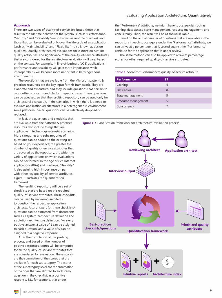
In fact, the questions and checklists that are available from the patterns & practices resources also include things that are applicable in technology-agnostic scenarios. More categories and subcategories of questions can be added to the existing set, based on your experience; the greater the number of quality-of-service attributes that are covered by the repository, the wider the variety of applications on which evaluations can be performed. In the age of rich Internet applications (RIAs) and mashups, “Usability” is also gaining high importance on par with other key quality-of-service attributes. Figure 1 illustrates the quantification framework.
The resulting repository will be a set of checklists that are based on the required quality-of-service attributes. These checklists can be used by reviewing architects to question the respective application architects. Also, answers for these checklists/questions can be extracted from documents such as a system-architecture definition and a solution-architecture definition. For every positive answer, a value of 1 can be assigned to each question, and a value of 0 can be assigned to a negative response.
After the completion of this probing process, and based on the number of positive responses, scores will be computed for all the quality-of-service attributes that are considered for evaluation. These scores are the summation of the scores that are available for each subcategory. The scores at the subcategory level are the summation of the ones that are allotted to each item/question in the checklist, as a positive response. Say, for example, that under
the “Performance” attribute, we might have subcategories such as caching, data access, state management, resource management, and concurrency. Then, the result will be as shown in Table 1.
Based on the actual number of questions that are available in the repository in each subcategory under the “Performance” attribute, we can arrive at a percentage that is scored against the “Performance” attribute for the application that is under review.
The same method can also be applied to arrive at percentage scores for other required quality-of-service attributes.
Figure 1: Quantification framework for architecture-evaluation process
Reviewing architect Application architect
+ + Ø1A1
Intuitive reports Architecture index
Interview output
Quantification framework
Prioritized quality attributes
Best-practices checklists/questions
Table 1: Score for “Performance” quality-of-service attribute
Performance 29
Caching 4
Data access 8
State management 5
Resource management 5
Concurrency 7
Evaluating Application Architecture, Quantitatively
The Architecture Journal 2310
Now, you might think that the average of the scores across the different quality-of-service attributes will give an overall score that indicates the quality of an application architecture. However, that might not be the actual case.
Let us see why.
Architectural Trade-OffsAn application cannot score 100 percent across all quality-of-service attributes. Architectural definition is the result of the trade-off decisions that are taken across various quality-of-service attributes. These trade-offs are arrived at, based on the architecturally significant scenarios and nature of the business domain for which the application is developed. Also, one quality-of-service attribute can have either a positive or negative impact on other quality-of-service attributes.
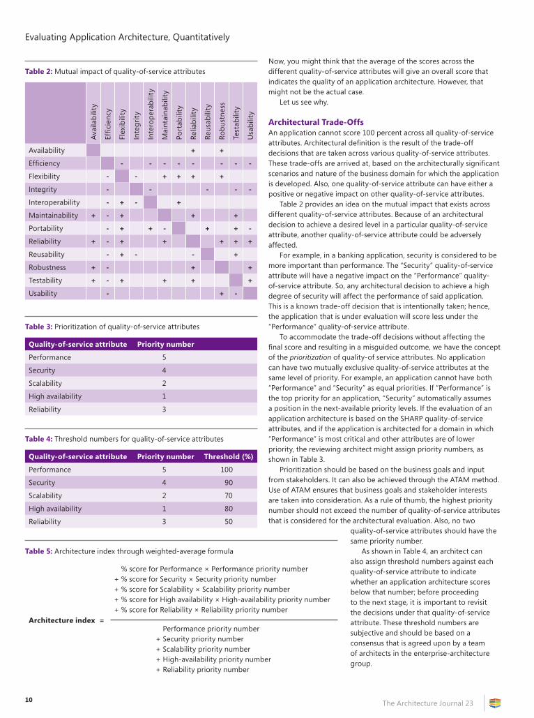
Table 2 provides an idea on the mutual impact that exists across different quality-of-service attributes. Because of an architectural decision to achieve a desired level in a particular quality-of-service attribute, another quality-of-service attribute could be adversely affected.
For example, in a banking application, security is considered to be more important than performance. The “Security” quality-of-service attribute will have a negative impact on the “Performance” quality-of-service attribute. So, any architectural decision to achieve a high degree of security will affect the performance of said application. This is a known trade-off decision that is intentionally taken; hence, the application that is under evaluation will score less under the “Performance” quality-of-service attribute.
To accommodate the trade-off decisions without affecting the final score and resulting in a misguided outcome, we have the concept of the prioritization of quality-of service attributes. No application can have two mutually exclusive quality-of-service attributes at the same level of priority. For example, an application cannot have both “Performance” and “Security” as equal priorities. If “Performance” is the top priority for an application, “Security” automatically assumes a position in the next-available priority levels. If the evaluation of an application architecture is based on the SHARP quality-of-service attributes, and if the application is architected for a domain in which “Performance” is most critical and other attributes are of lower priority, the reviewing architect might assign priority numbers, as shown in Table 3.
Prioritization should be based on the business goals and input from stakeholders. It can also be achieved through the ATAM method. Use of ATAM ensures that business goals and stakeholder interests are taken into consideration. As a rule of thumb, the highest priority number should not exceed the number of quality-of-service attributes that is considered for the architectural evaluation. Also, no two
quality-of-service attributes should have the same priority number.
As shown in Table 4, an architect can also assign threshold numbers against each quality-of-service attribute to indicate whether an application architecture scores below that number; before proceeding to the next stage, it is important to revisit the decisions under that quality-of-service attribute. These threshold numbers are subjective and should be based on a consensus that is agreed upon by a team of architects in the enterprise-architecture group.
Table 2: Mutual impact of quality-of-service attributes
Avai
labi
lity
Effic
ienc
y
Flex
ibili
ty
Inte
grity
Inte
rope
rabi
lity
Mai
ntai
nabi
lity
Port
abili
ty
Relia
bilit
y
Reus
abili
ty
Robu
stne
ss
Test
abili
ty
Usa
bilit
y
Availability + +
Efficiency - - - - - - - -
Flexibility - - + + + +
Integrity - - - - -
Interoperability - + - +
Maintainability + - + + +
Portability - + + - + + -
Reliability + - + + + + +
Reusability - + - - +
Robustness + - + +
Testability + - + + + +
Usability - + -
Table 3: Prioritization of quality-of-service attributes
Quality-of-service attribute Priority number
Performance 5
Security 4
Scalability 2
High availability 1
Reliability 3
Table 4: Threshold numbers for quality-of-service attributes
Quality-of-service attribute Priority number Threshold (%)
Performance 5 100
Security 4 90
Scalability 2 70
High availability 1 80
Reliability 3 50
Table 5: Architecture index through weighted-average formula
Architecture index =
% score for Performance × Performance priority number+ % score for Security × Security priority number+ % score for Scalability × Scalability priority number+ % score for High availability × High-availability priority number+ % score for Reliability × Reliability priority number
Performance priority number + Security priority number + Scalability priority number + High-availability priority number + Reliability priority number

11
Evaluating Application Architecture, Quantitatively
The Architecture Journal 23
If an application scores below the threshold values, it is a clear indication of the level at which the application architecture is below the mark.
This will also be especially helpful in mergers and acquisitions (M&As). Say that when Company A acquires Company B and carries out an assessment process, Company A might retire the applications that score well below the threshold values.
Architecture IndexAfter consideration of the scores for all quality-of-service attributes and prioritization of those attributes, the final quality of the application architecture can be arrived at by using the weighted-average formula, as shown in Table 5 on page 10.
This weighted-average formula will result in a single number, which can be called the “Architecture index.” Table 6 shows an architecture-index value that is based on the application of the weighted-average formula to the sample scores of different quality-of-service attributes, and their respective priority numbers.
The architecture index will be between 0 and 100. This number gives an immediate sense of where that application architecture stands. Because the resulting number is based on the best practices and guidelines that are provided by platform vendors, it will reflect how best the application can be architected. For instance, an evaluation that is performed based on the checklists/questions that are provided by the Microsoft patterns & practices and results in a lower architecture index will indicate that the application architecture does not adhere to the proven best practices.
Because a positive or negative response to a question directly contributes to a score of a particular quality-of-service attribute, we can easily identify the impact of a particular architectural decision on a particular quality-of-service attribute and, hence, the overall quality of the application architecture.
Intuitive ReportsAlthough a single architecture index gives a clear view of the strength or quality of an application architecture, it must have some intuitive reports that highlight the weak areas of an application architecture, so that they can be used to carry out an effective reengineering or refactoring process.
It makes sense to have a tool or to build small software to automate the entire process and generate reports. Microsoft Office Excel can perform wonders, with few scripts and limited effort. For an application architect to know immediately what went wrong (based on the architecture index) and react immediately, these intuitive reports play a significant role.
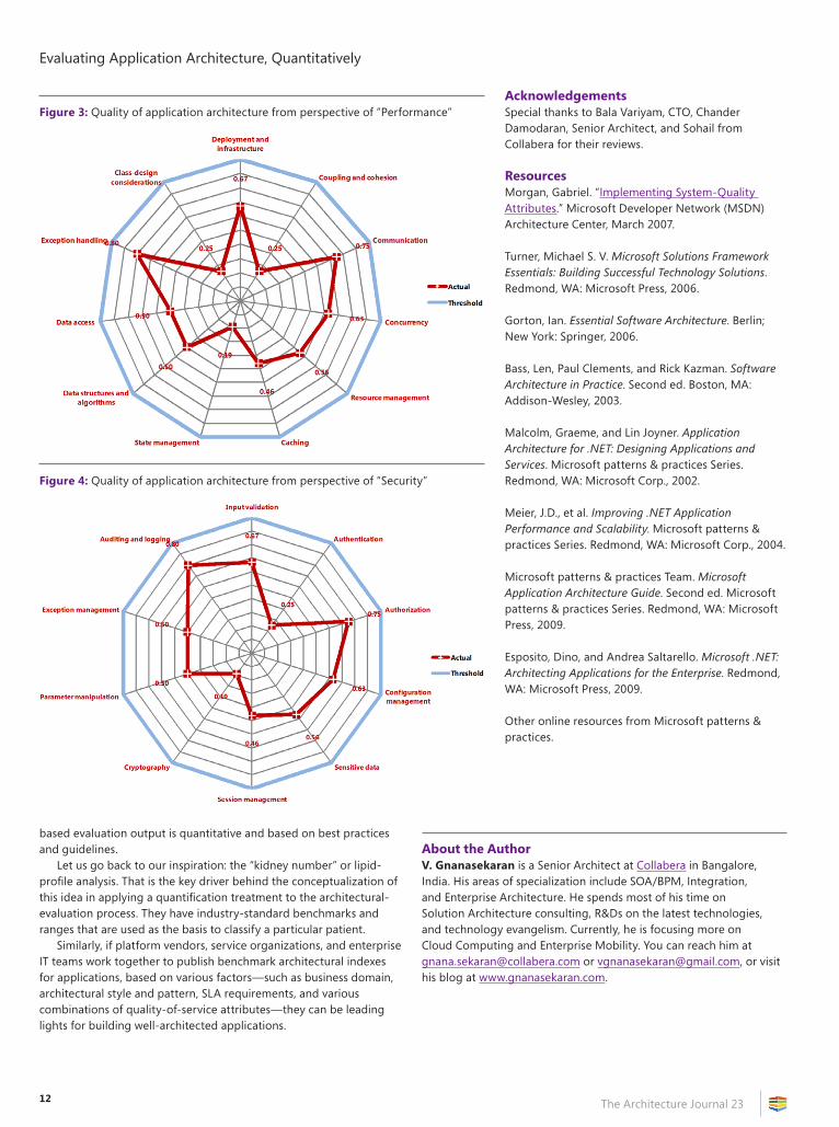
Figure 2, and Figures 3 and 4 on page 12, show screen shots of some of the reports that are generated by the tool and that resulted in our past successful architectural-consulting engagements.
Say, for example, after an evaluation process, that an application architecture scores 49 percent. The application architect can immediately identify under which quality-of-service attribute it is scoring low. If it scored low in “Performance,” the architect could go to the performance-analysis report, which will show the scores across different subcategories (such as caching and state
management). If it scored less under a particular subcategory—for example, caching—the architect could trace back from that point to see why the architecture scored so many zeros under that subcategory. The architect could also get a handle on how a particular decision might affect a particular quality-of-service attribute and, hence, the overall architecture.
In scenarios in which the existing application architectures are evaluated, application architects can use these reports in meetings with stakeholders to convey why application architecture is considered inferior, as well as to highlight areas that need refocus. This will drive corrective actions that must be taken to revamp respective applications.
ConclusionA quantitative architecture-evaluation process provides a crystal-clear picture of the quality of an application architecture. The output of this process helps in taking concrete, corrective decisions. While the quantitative evaluation of application architecture is more promising and results in a clearer picture of the state of the architecture of existing applications or the proposed architecture of new applications that are to be built, it cannot replace an application-architecture process that is based on a scenario-based method such as ATAM. ATAM involves a more elaborate exercise that is based on architecturally significant scenarios and could be supplemented by a quantitative evaluation. While the output of a method such as ATAM is qualitative and based on scenario-based analysis, this framework-
Figure 2: Overall-architecture quality of application
Table 6: Scores of quality-of-service attributes & corresponding architecture index
Quality-of-service attribute Priority numberPercentage gained (%)
Performance 5 86.30
Security 4 82.00
Scalability 2 77.00
High availability 1 59.00
Reliability 3 46.00
Architecture index 74.03
Evaluating Application Architecture, Quantitatively
The Architecture Journal 2312
based evaluation output is quantitative and based on best practices and guidelines.
Let us go back to our inspiration: the “kidney number” or lipid-profile analysis. That is the key driver behind the conceptualization of this idea in applying a quantification treatment to the architectural-evaluation process. They have industry-standard benchmarks and ranges that are used as the basis to classify a particular patient.
Similarly, if platform vendors, service organizations, and enterprise IT teams work together to publish benchmark architectural indexes for applications, based on various factors—such as business domain, architectural style and pattern, SLA requirements, and various combinations of quality-of-service attributes—they can be leading lights for building well-architected applications.
AcknowledgementsSpecial thanks to Bala Variyam, CTO, Chander Damodaran, Senior Architect, and Sohail from Collabera for their reviews.
ResourcesMorgan, Gabriel. “Implementing System-Quality Attributes.” Microsoft Developer Network (MSDN) Architecture Center, March 2007.
Turner, Michael S. V. Microsoft Solutions Framework Essentials: Building Successful Technology Solutions. Redmond, WA: Microsoft Press, 2006.
Gorton, Ian. Essential Software Architecture. Berlin; New York: Springer, 2006.
Bass, Len, Paul Clements, and Rick Kazman. Software Architecture in Practice. Second ed. Boston, MA: Addison-Wesley, 2003.
Malcolm, Graeme, and Lin Joyner. Application Architecture for .NET: Designing Applications and Services. Microsoft patterns & practices Series. Redmond, WA: Microsoft Corp., 2002.
Meier, J.D., et al. Improving .NET Application Performance and Scalability. Microsoft patterns & practices Series. Redmond, WA: Microsoft Corp., 2004.
Microsoft patterns & practices Team. Microsoft Application Architecture Guide. Second ed. Microsoft patterns & practices Series. Redmond, WA: Microsoft Press, 2009.
Esposito, Dino, and Andrea Saltarello. Microsoft .NET: Architecting Applications for the Enterprise. Redmond, WA: Microsoft Press, 2009.
Other online resources from Microsoft patterns & practices.
About the AuthorV. Gnanasekaran is a Senior Architect at Collabera in Bangalore, India. His areas of specialization include SOA/BPM, Integration, and Enterprise Architecture. He spends most of his time on Solution Architecture consulting, R&Ds on the latest technologies, and technology evangelism. Currently, he is focusing more on Cloud Computing and Enterprise Mobility. You can reach him at [email protected] or [email protected], or visit his blog at www.gnanasekaran.com.
Figure 3: Quality of application architecture from perspective of “Performance”
Figure 4: Quality of application architecture from perspective of “Security”
13The Architecture Journal 23
Summary
This article proposes a set of techniques and practices to leverage the agile approach to software architecture—increasing overall quality, streamlining development practices, and providing business value as a constant flow.
The article describes issues that are related to component API design and behavior-driven design, continuous measurement of complexity, automated quality-attribute evaluation, and design rationale recording. The reader should take away from the article several techniques to research and try, a basic development life cycle, and some leads for further investigation (starting with the provided bibliography).
IntroductionEven while agile methodologies are getting widely accepted in the development world, there is still a lot of debate about how to apply them to the architectural space. One of the most conflictive issues stems around “big design upfront,” which is strongly discouraged by agile practitioners, and the traditional approach to architectural design.
This article proposes a set of team dynamics, conceptual practices, and specific technologies to embed software architecture within the agile approach—keeping up the shared goals of technical excellence, streamlined development practices, and a constant and ever-increasing flow of business.
It is the hope of the authors that readers can later compare our experiences with their own and provide further discussion, so as to keep improving our professional corpus.
Architectural Dynamics in Agile TeamsOne of the 12 principles of the Agile Manifesto states that “the best architectures, requirements, and designs emerge from self-organizing teams.”1 We take this to heart—especially, the reference to our shared specialization.
While architecture is an activity that is historically performed with an emphasis on the early stages of a project, the main focus of agile development is on emergent design and iterative production—creating a series of interesting challenges down the road.
First of all, agile makes a big push toward shared responsibility and, thus, dilutes the traditional role of the architect as the one who
“defines” the higher-level design of a solution. In this new approach, architecture (as most other development activities) is something that is performed by the whole team—preserving its multidisciplinary nature. This does not imply that the architect profile goes away, as with all the other roles; it means that while someone contributes with a broader and probably more experienced perspective (usually leading in this aspect), the whole team participates and understands the implications of the design decisions that it makes, and continuously evaluates them.
In our experience, key considerations—such as the modularity strategy, how communication is handled within and outside the application, and how data and services are accessed and abstracted—are successfully defined and implemented when the whole development team establishes a consensus about these issues. In this way, team members fully understand the consequences of the selected alternatives, remain aware of their initial assumptions thorough the solution life cycle, and quickly raise concerns when their validity is affected.
Most of these challenges are usually tackled by folding architectural discussion and revision into the regular meetings that take place over the course of an iteration—such as planning and review meetings, and frequent sync-ups and design meetings with plenty of white boarding and open talk. It is also worthwhile to have the most important guidelines permanently exposed in an informative space, including diagrams, checklists or reference charts around the walls, and semipermanent flip charts that are used as posters.
This article does not cover in detail specific techniques that apply to coordinating several subteams; mainly, it mirrors the standard guidelines about the “Scrum of Scrums”.2 The addition to such activities is a stronger focus on the preservation of conceptual integrity—thus, planning frequent high-level design meetings between teams. Again, these meetings should avoid becoming architect meetings; while the contribution of team members who have a stronger architectural background is obviously important, it is very important for other members to participate. Even the less experienced team members can provide a somewhat naïve perspective to some discussion—promptly flagging complexity excesses that are a professional malady among us architects.
To close on the team dynamics, as the agile perspective goes over the standard view of the development team and extends to customers, operations personnel, and other stakeholders, expectation management is a big deal also for the solution architecture. As the next section shows, there is a strong emphasis on mapping the needs and goals of these actors to the architectural constraints and converting the most important into strong metrics to be evaluated.
Software Architecture in the Agile Life Cycleby Diego Fontdevila and Martín Salías
Software Architecture in the Agile Life Cycle
The Architecture Journal 2314
Agile Architecture Patterns and PracticesSashimiThere are several common approaches to support the previously described dynamics and keep the agile principles of high customer involvement and feedback, continuous delivery of working software, and attention to technical quality, among others.
One of the most common patterns that we use to avoid the perils of big design up front is the “sashimi” approach to the architectural definition. In this approach, instead of spending a lot of time designing and implementing the different moving parts around layers and tiers, crosscutting concerns, and so on, we build the minimal amount of code that is needed to connect all of the pieces and start building the actual functionality on top—providing an early end-to-end experience of the results. Indeed, the focus is more on the API level of the infrastructure, and not the actual implementation, which is usually mocked up for the first few iterations.
The main purpose is to avoid building architecture components that are hard to use or tying the business logic and other high-level abstractions to the underlying implementation. As iterations progress, the actual implementation is incrementally completed, following the needs of the functional part of the application. At some point, such things as load or stress testing that is performed over the functional side of the solution will even require fine-tuning of these components for robustness, increased performance, resource consumption, and so on.
To be able to support this emergent implementation over architectural pieces, definition of a highly decoupled API is the most critical factor. Whenever implementation details permeate outside the API—hence, coupling with its consumers—refactoring the architectural components becomes a nightmare. That is why API design becomes a key activity in the earlier stages, and why starting with no implementation at all is a better approach.
This practice applies even when using third-party components, which is both common and generally advisable, for the most part. In such cases, existing default implementations for those third-party components provide early support modules; and, many times, configuration is needed instead of coding in the early stages.
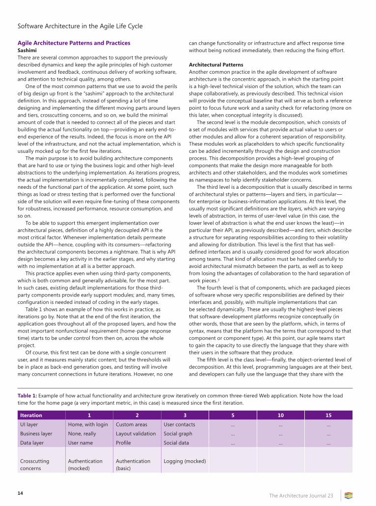
Table 1 shows an example of how this works in practice, as iterations go by. Note that at the end of the first iteration, the application goes throughout all of the proposed layers, and how the most important nonfunctional requirement (home-page response time) starts to be under control from then on, across the whole project.
Of course, this first test can be done with a single concurrent user, and it measures mainly static content; but the thresholds will be in place as back-end generation goes, and testing will involve many concurrent connections in future iterations. However, no one
can change functionality or infrastructure and affect response time without being noticed immediately, then reducing the fixing effort.
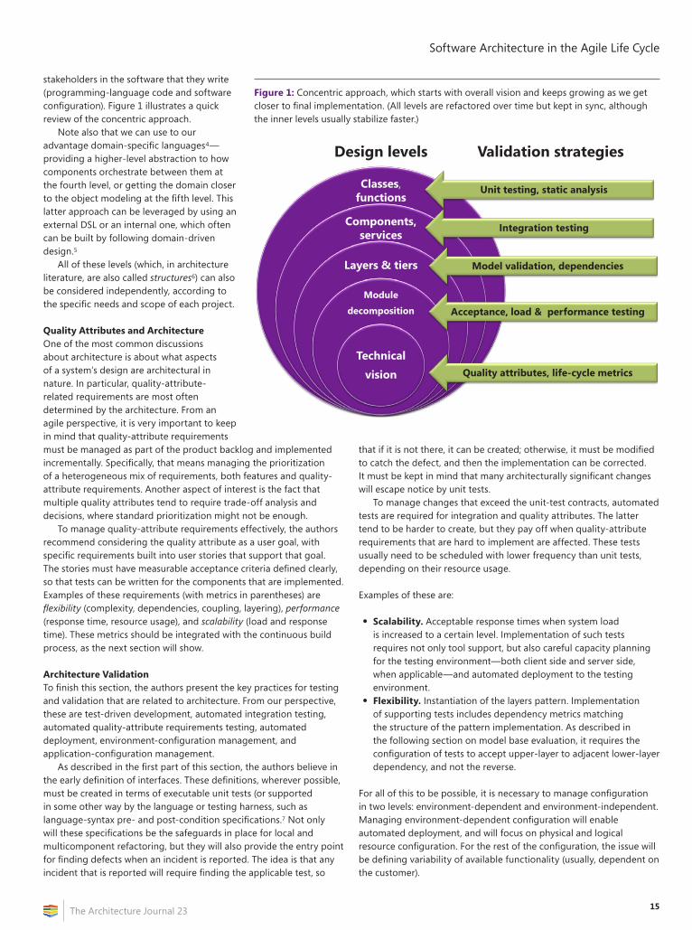
Architectural PatternsAnother common practice in the agile development of software architecture is the concentric approach, in which the starting point is a high-level technical vision of the solution, which the team can shape collaboratively, as previously described. This technical vision will provide the conceptual baseline that will serve as both a reference point to focus future work and a sanity check for refactoring (more on this later, when conceptual integrity is discussed).
The second level is the module decomposition, which consists of a set of modules with services that provide actual value to users or other modules and allow for a coherent separation of responsibility. These modules work as placeholders to which specific functionality can be added incrementally through the design and construction process. This decomposition provides a high-level grouping of components that make the design more manageable for both architects and other stakeholders, and the modules work sometimes as namespaces to help identify stakeholder concerns.
The third level is a decomposition that is usually described in terms of architectural styles or patterns—layers and tiers, in particular—for enterprise or business-information applications. At this level, the usually most significant definitions are the layers, which are varying levels of abstraction, in terms of user-level value (in this case, the lower level of abstraction is what the end user knows the least)—in particular their API, as previously described—and tiers, which describe a structure for separating responsibilities according to their volatility and allowing for distribution. This level is the first that has well-defined interfaces and is usually considered good for work allocation among teams. That kind of allocation must be handled carefully to avoid architectural mismatch between the parts, as well as to keep from losing the advantages of collaboration to the hard separation of work pieces.3
The fourth level is that of components, which are packaged pieces of software whose very specific responsibilities are defined by their interfaces and, possibly, with multiple implementations that can be selected dynamically. These are usually the highest-level pieces that software-development platforms recognize conceptually (in other words, those that are seen by the platform, which, in terms of syntax, means that the platform has the terms that correspond to that component or component type). At this point, our agile teams start to gain the capacity to use directly the language that they share with their users in the software that they produce.
The fifth level is the class level—finally, the object-oriented level of decomposition. At this level, programming languages are at their best, and developers can fully use the language that they share with the
Table 1: Example of how actual functionality and architecture grow iteratively on common three-tiered Web application. Note how the load time for the home page (a very important metric, in this case) is measured since the first iteration.
Iteration 1 2 3 5 10 15
UI layer Home, with login Custom areas User contacts … … …
Business layer None, really Layout validation Social graph … … …
Data layer User name Profile Social data … … …
Crosscutting concerns
Authentication (mocked)
Authentication (basic)
Logging (mocked)
15
Software Architecture in the Agile Life Cycle
The Architecture Journal 23
stakeholders in the software that they write (programming-language code and software configuration). Figure 1 illustrates a quick review of the concentric approach.
Note also that we can use to our advantage domain-specific languages4—providing a higher-level abstraction to how components orchestrate between them at the fourth level, or getting the domain closer to the object modeling at the fifth level. This latter approach can be leveraged by using an external DSL or an internal one, which often can be built by following domain-driven design.5
All of these levels (which, in architecture literature, are also called structures6) can also be considered independently, according to the specific needs and scope of each project.
Quality Attributes and ArchitectureOne of the most common discussions about architecture is about what aspects of a system’s design are architectural in nature. In particular, quality-attribute-related requirements are most often determined by the architecture. From an agile perspective, it is very important to keep in mind that quality-attribute requirements must be managed as part of the product backlog and implemented incrementally. Specifically, that means managing the prioritization of a heterogeneous mix of requirements, both features and quality-attribute requirements. Another aspect of interest is the fact that multiple quality attributes tend to require trade-off analysis and decisions, where standard prioritization might not be enough.
To manage quality-attribute requirements effectively, the authors recommend considering the quality attribute as a user goal, with specific requirements built into user stories that support that goal. The stories must have measurable acceptance criteria defined clearly, so that tests can be written for the components that are implemented. Examples of these requirements (with metrics in parentheses) are flexibility (complexity, dependencies, coupling, layering), performance (response time, resource usage), and scalability (load and response time). These metrics should be integrated with the continuous build process, as the next section will show.
Architecture ValidationTo finish this section, the authors present the key practices for testing and validation that are related to architecture. From our perspective, these are test-driven development, automated integration testing, automated quality-attribute requirements testing, automated deployment, environment-configuration management, and application-configuration management.
As described in the first part of this section, the authors believe in the early definition of interfaces. These definitions, wherever possible, must be created in terms of executable unit tests (or supported in some other way by the language or testing harness, such as language-syntax pre- and post-condition specifications.7 Not only will these specifications be the safeguards in place for local and multicomponent refactoring, but they will also provide the entry point for finding defects when an incident is reported. The idea is that any incident that is reported will require finding the applicable test, so
that if it is not there, it can be created; otherwise, it must be modified to catch the defect, and then the implementation can be corrected. It must be kept in mind that many architecturally significant changes will escape notice by unit tests.
To manage changes that exceed the unit-test contracts, automated tests are required for integration and quality attributes. The latter tend to be harder to create, but they pay off when quality-attribute requirements that are hard to implement are affected. These tests usually need to be scheduled with lower frequency than unit tests, depending on their resource usage.
Examples of these are:
• Scalability. Acceptable response times when system load is increased to a certain level. Implementation of such tests requires not only tool support, but also careful capacity planning for the testing environment—both client side and server side, when applicable—and automated deployment to the testing environment.
• Flexibility. Instantiation of the layers pattern. Implementation of supporting tests includes dependency metrics matching the structure of the pattern implementation. As described in the following section on model base evaluation, it requires the configuration of tests to accept upper-layer to adjacent lower-layer dependency, and not the reverse.
For all of this to be possible, it is necessary to manage configuration in two levels: environment-dependent and environment-independent. Managing environment-dependent configuration will enable automated deployment, and will focus on physical and logical resource configuration. For the rest of the configuration, the issue will be defining variability of available functionality (usually, dependent on the customer).
Figure 1: Concentric approach, which starts with overall vision and keeps growing as we get closer to final implementation. (All levels are refactored over time but kept in sync, although the inner levels usually stabilize faster.)
Classes, functions
Components, services
Layers & tiers
Module
decomposition
Technical
vision
Design levels Validation strategies
Quality attributes, life-cycle metrics
Acceptance, load & performance testing
Model validation, dependencies
Integration testing
Unit testing, static analysis

Software Architecture in the Agile Life Cycle
The Architecture Journal 2316
The next section discusses the use of available technologies for the implementation of these practices.
Specific Techniques and TechnologiesTo implement reasonably the techniques that the previous section described, it is necessary to use appropriate tools and technologies, not only because of the expense that is incurred, but also to provide the necessary discipline through automation.
As the agile mindset stated in its manifesto, individuals and interactions are more important than processes and tools; from there, however, the agile world has derived a helpful set of tools that take tedious manual tasks away from people and make them easy to execute fast and frequently—providing a lot of feedback upon which individuals can act. For our architectural quest, the authors follow the same principles and basic ideas and extend them to cover the concepts that have been discussed.
The first level of technologies that are used can comprise regular testing tools and frameworks, such as unit-testing tools—from the traditional xUnit (such as jUnit, NUnit, cppUnit, and MS Test) to the ones that come from behavior-driven development8 (such as RSpec, xUnit.net, JBehave, and Cucumber, among others). Included also are user-acceptance or functional testing tools (such as Fit/Fitnesse, Selenium, and Watir, among others) and a host of technologies that are needed for performance and stress testing. All of these, of course, run at an individual level, as well as on the build server, and with different frequencies (unit tests in every check-in, functional a few times a day, load and stress usually over the night, and so on).
In short, we build up from the basics of the appropriate development practices—adding some specific test at the unit, acceptance, or stress level to validate some architectural concerns.
To this standard tooling, a second level is added—with more specific checks over quality attributes, such as lines of code per class/module, code-coverage statistics, static analysis, style analysis, cyclomatic complexity, afferent and efferent coupling, dependencies, and more. Some of the tools that are used in this space are (for .NET) FXCop, StyleCop, NDepend, and built-in tools in Microsoft Visual Studio Team System; and (for Java) FindBugs, JDepend, Checkstyle, Lattix, and built-in features on IntelliJ IDEA. Within the realm of dynamic languages such as Ruby, JavaScript, and Python, this is a less developed area, because of the inherent difficulty of performing static analysis on them. However, there is strong evidence that shows that as the runtime engines are going increasingly the way of just-in-time compilers, this gap will be filled soon.
Then, there is a third level of metrics about flexibility and maintainability that has to do with the project life cycle itself—metrics such as code-churn, volatility, correlations, and adherence to the architectural models. In this space, Visual Studio Team System is making great strides, while there are many people who implement part of this by using build-tool plug-ins or custom scripts that crunch data and produce reports or alarms, based on data that comes from the source repository, build server, issue tracker, testing environments, and modeling tools.
Indeed, to be able to perform validation against an architectural model, such a model has to be in place. To do so, we can pick among myriad tools—from Enterprise Architect (or some of the Rational suite of tools) to Visual Studio Team System. What is important here is to take the time to automate the process to extract the relevant metadata that is needed to validate the code, references between packages or services, or module composition.
Additionally, it is very important to distinguish the code or module view of the system from the runtime view of the system during evaluation. Runtime characteristics are usually harder to perceive, but their high implementation costs make early analysis and testing worthwhile. Finally, it is very useful to learn also how to perform some level of reverse-engineering—allowing to grab some information from the actual implementation into the model, and automating part of the documentation chores.
The final step of this methodology involves the deployment and configuration of the different staging environments, in which virtualization becomes an incredible enabler—allowing for quick turn-on and turn-off of all the needed environments (with baseline configuration), where we can use remote scripting to perform the deployment of the latest build and configuration to any of these environments, and then perform all sorts of testing. The current power of virtualization platforms such as VMWare, Hyper-V, and others makes it really easy to manage multiple basic images—taking and reverting to snapshots, even across distributed physical machines.
Of course, all of this is not something that the authors encourage anyone to try setting up from day one. Instead, you should increasingly add over each iteration, but have all of the appropriate (and project-relevant) techniques folded into the main plan, to ensure that these controls are getting into place as the project goes on.
ConclusionThe authors of this article believe that architectural considerations are fundamental for delivering value in most software projects—also, that agile teams have much to offer in terms of mechanics, techniques, and tools for the software-architecture community. These contributions are best considered in terms of the development of a language that is shared by all stakeholders and spans the spectrum from the user’s view of the system to the actual code. This language consists of the set of both user requirements and design decisions that are made during the life of the product. Its final purpose is to allow users and teams to create excellent results that will provide value, according to the expectations of stakeholders, throughout the lifetime of the product.
References1 Fowler, Martin, et al. “Principles Behind the Agile Manifesto.”
Manifesto for Agile Software Development Web site, 2001.2 Cohn, Mike. “Advice on Conducting the Scrum of Scrums
Meetings.” Mountain Goat Software Web site, May 2007. (Originally published in Scrum Alliance Web site.)
3 Austin, Robert D., and Lee Devin. Artful Making: What Managers Need to Know About How Artists Work. New York: Prentice Hall, 2003. (Page 144.)
4 Martin Fowler is currently writing a whole book on DSL, but the work in progress is available at http://martinfowler.com/dslwip/.
5 Evans, Eric. Domain-Driven Design: Tackling Complexity in the Heart of Software. Boston: MA, Addison-Wesley, 2004.
6 Bass, Len, Paul Clements, and Rick Kazman. Software Architecture in Practice. Second ed. Boston, MA: Addison-Wesley, 2003.
7 Mandrioli, Dino, and Bertrand Meyer. Advances in Object-Oriented Software Engineering. New York: Prentice Hall, 1991. (Chapter 1, “Design by Contract.”)
8 North, Dan. “Introducing BDD.” http://dannorth.net/introducing-bdd. DanNorth.net Web site, September 20, 2006. (Originally published in Better Software Magazine Web site.)
17
Software Architecture in the Agile Life Cycle
The Architecture Journal 23
About the AuthorsDiego Fontdevila ([email protected]), Professional Services Director at Grupo Esfera, specializes in software architecture and agile methodologies. He has 13 years of experience as both software developer and university teacher. Currently, Diego is a Master of Software Engineering Management student at Carnegie Mellon University. You can view his published articles (in Spanish) at http://diegofontdevila.wordpress.com/articulos.
Martín Salías ([email protected]), Senior Architect at Southworks, has more than 25 years in the software industry, working on different industries for customers around the world, and covering many platforms and languages. He is a member of the Agile Alliance and has been awarded as a Microsoft MVP since 2002. You can view his published articles at http://salias.com.ar/articles.asp.
BlogsIn English: http://blogs.southworks.net/msalias/In Spanish: http://blog.salias.com.ar
Modeling Just Enough and Rightby Mohana Krishna and S.V. Subrahmanya
Architecture modeling is an increasingly key component of the software-development life cycle (SDLC)—serving such important needs as stakeholder communication, architecture comprehension, analysis, and verification. However, it is often the case that it does not materially contribute to the end product: the deployed code. For this specific reason, it becomes important to be focused on the purpose and value, so as to optimize the effort that is expended on it.
It is important to decide at the outset the drivers to carry out modeling and the right level of detail and rigor. Certain considerations—such as who are the stakeholders, the aspects of the architecture that are modeled and their relative importance, and the available tool support for transformation to downstream artifacts—typically influence these decisions. In this regard, it is important to note that effort is spent not just in creation of the model, but also in maintenance, so that it remains aligned to subsequent artifacts and stays relevant to the original purpose for which it was intended.
A key consideration in modeling—and a key determinant of how efficiently and optimally the objectives of modeling are met—is the partitioning and representation of the content. Partitioning of content is necessary to isolate aspects that represent different concerns and enable an overall better grasp of the architecture. This is typically achieved through viewpoints and views that together make up the model. Clear focus and careful analysis are required to determine and prioritize the essential structural and dynamic aspects of the system that are appropriate to a given context, as well as to avoid the pitfalls of coming up with “ivory-tower” architectures and over-engineering.
The representation of content often poses a challenge in being amenable to both human- and machine-processing of the model. The choice of notation and availability of tool support play a key role in providing the ability to derive one representation from another. The wide adoption of UML notation as a de facto standard, and its systematic evolution, has encouraged tool vendors to put their weight behind it. However, choosing the right subset of UML diagrams to represent the chosen aspects can prove tricky and, again, requires clear focus and a mindset of thrift.
While there exists no fixed silver-bullet prescription for just the right amount of modeling (besides the points that have been previously mentioned), the agile approach of a brief architecture-envisioning phase to generate a blueprint, followed by a strictly need-driven incremental refinement along the way, seems to offer reasonable hope.
Mohana Krishna ([email protected]) has been a practicing architect for over 15 years and is presently engaged in architecture-competency development at Infosys Technologies.
S.V. Subrahmanya ([email protected]) heads the E-COM Research Labs in the Education & Research Department at Infosys Technologies.
18 The Architecture Journal 23
Summary
This article describes the four pillars of a holistic enterprise architecture: architectural models, framework, methodology, and solution models. It also explains the business and technology gains and demystifies the practice of implementing a successful holistic enterprise architecture.
IntroductionIt is only within the past 20 years that we have begun to develop an art and science for identifying and defining the graphical and textual descriptions of whole enterprises. Until this time, any art or science that we had related to this endeavor pertained to parts of enterprises—for example, organizational design and/or systems development. Because the focus of this article is on enterprise architecture, have there been successful enterprises that were never architected?
Yes. However, they were successful in relation to other non-architected enterprises. Moreover, the pace of change was slower in the industrial age, compared with the information age of today. Contemporary enterprises have to be able to adjust much more rapidly to meet changing demands in the face of global competition. This makes it critical to have readily available descriptive representations of one’s enterprise to use as a basis for making change.
The age-old question now arises in enterprises: How can one change something that one cannot “see”? How does one “see” an enterprise?
Benefits of a Holistic Enterprise ArchitectureThere are many benefits for both the business and technology areas of holistic enterprise architecture, but the following are a few of the greatest gains that have been observed.
Business Benefits• Developing and communicating a broad understanding of your
business—a confirming enterprise-self realization that is clear and concise.
• Identifying and mitigating potential risk in your selected paths of action or investment—thereby, reducing unintended consequences.
• Clarifying your business priorities and identifying your core competencies—enabling you to assign key resources to projects confidently, and leveraging top talent for critical needs.
Technology Benefits• Creating a practical and efficient means to manage your
information-technology portfolios, rationalizing your existing systems and projects to gain significant cost reductions, and helping you remove waste and redundancy in your information-system deployments.
• Aligning your technology investments and assets to project initiatives that demonstrate direct support of priority business goals, competencies, and needs.
• Identifying, classifying, representing, developing, and accumulating in an accessible portfolio your architected, highly reusable technology assets.
• Identifying and mitigating potential impacts of your proposed solutions, services, or changes—thereby, addressing all areas that are affected in the design and negotiation of new or updated solutions, and reducing your exposure to the risk of unintended impacts and degradation.
There is much confusion today in the terminology that surrounds enterprise architecture. Let us attempt to demystify these terms and concepts.
Demystifying EnterpriseAn enterprise is any purposeful undertaking, commonly used in connection with undertakings that have ongoing operations. Mowing your personal lawn is an undertaking, but you probably would not refer to it as an enterprise. A company that mows lawns for profit is an enterprise.
All enterprises have architecture simply by virtue of their existence, whether they are explicitly represented or not. Unfortunately, this does not mean that all enterprises have been explicitly architected, for that would imply that deliberate and disciplined thinking went into their design and implementation. Most enterprises “evolve” and grow or shrink over time, without much attention being given to identifying and defining their fundamental components; so that (among other things) decisions can be made to reuse existing components to satisfy new requirements, eliminate redundancies, or eliminate activities that do not align with strategic business planning.
Enterprises are complicated, because they are composed of not only fixed, physical components, but also behavioral components such as people and business processes.
Demystifying ArchitectureThe architecture of anything is:
• Its fundamental organization—embodied in its components and their relationships to each other and their environment.
• The principles that govern its design and evolution.
Driving Efficiency and Innovation by Consistently Managing Complexity and Changeby Samuel B. (Sam) Holcman
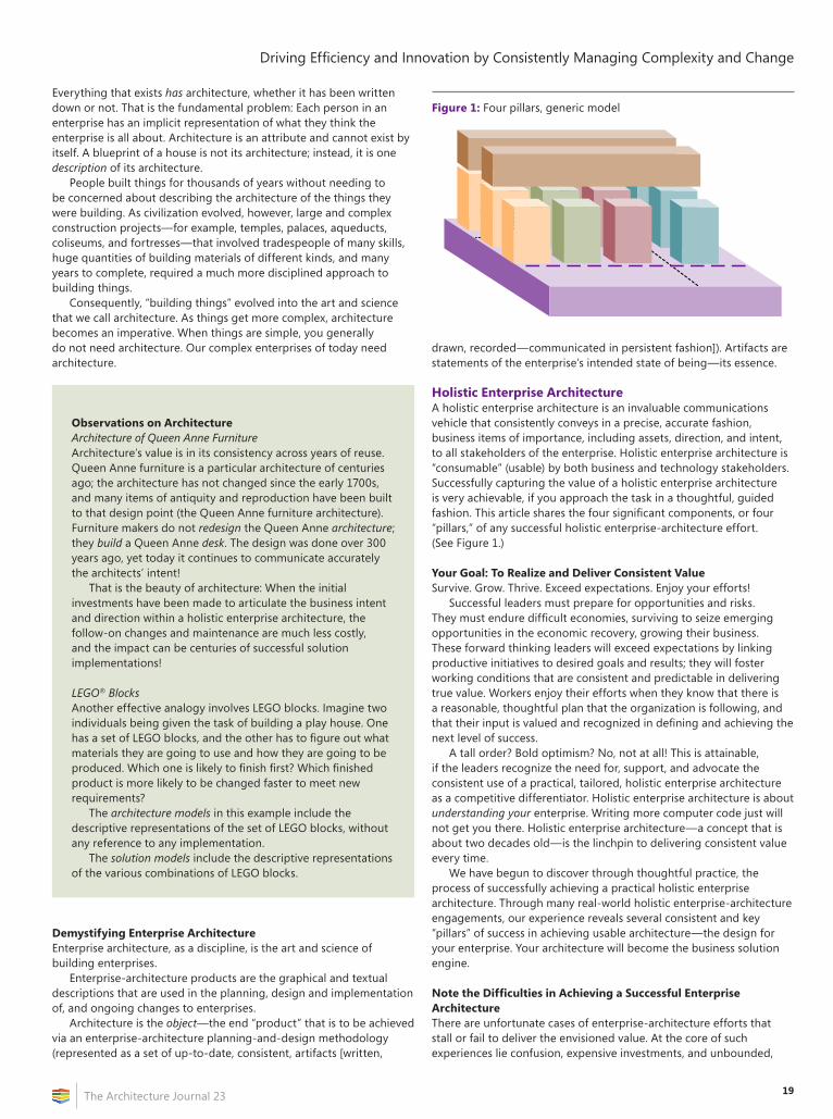
19
Driving Efficiency and Innovation by Consistently Managing Complexity and Change
The Architecture Journal 23
Everything that exists has architecture, whether it has been written down or not. That is the fundamental problem: Each person in an enterprise has an implicit representation of what they think the enterprise is all about. Architecture is an attribute and cannot exist by itself. A blueprint of a house is not its architecture; instead, it is one description of its architecture.
People built things for thousands of years without needing to be concerned about describing the architecture of the things they were building. As civilization evolved, however, large and complex construction projects—for example, temples, palaces, aqueducts, coliseums, and fortresses—that involved tradespeople of many skills, huge quantities of building materials of different kinds, and many years to complete, required a much more disciplined approach to building things.
Consequently, “building things” evolved into the art and science that we call architecture. As things get more complex, architecture becomes an imperative. When things are simple, you generally do not need architecture. Our complex enterprises of today need architecture.
Observations on ArchitectureArchitecture of Queen Anne FurnitureArchitecture’s value is in its consistency across years of reuse. Queen Anne furniture is a particular architecture of centuries ago; the architecture has not changed since the early 1700s, and many items of antiquity and reproduction have been built to that design point (the Queen Anne furniture architecture). Furniture makers do not redesign the Queen Anne architecture; they build a Queen Anne desk. The design was done over 300 years ago, yet today it continues to communicate accurately the architects’ intent!
That is the beauty of architecture: When the initial investments have been made to articulate the business intent and direction within a holistic enterprise architecture, the follow-on changes and maintenance are much less costly, and the impact can be centuries of successful solution implementations!
LEGO® BlocksAnother effective analogy involves LEGO blocks. Imagine two individuals being given the task of building a play house. One has a set of LEGO blocks, and the other has to figure out what materials they are going to use and how they are going to be produced. Which one is likely to finish first? Which finished product is more likely to be changed faster to meet new requirements?
The architecture models in this example include the descriptive representations of the set of LEGO blocks, without any reference to any implementation.
The solution models include the descriptive representations of the various combinations of LEGO blocks.
Demystifying Enterprise ArchitectureEnterprise architecture, as a discipline, is the art and science of building enterprises.
Enterprise-architecture products are the graphical and textual descriptions that are used in the planning, design and implementation of, and ongoing changes to enterprises.
Architecture is the object—the end “product” that is to be achieved via an enterprise-architecture planning-and-design methodology (represented as a set of up-to-date, consistent, artifacts [written,
drawn, recorded—communicated in persistent fashion]). Artifacts are statements of the enterprise’s intended state of being—its essence.
Holistic Enterprise ArchitectureA holistic enterprise architecture is an invaluable communications vehicle that consistently conveys in a precise, accurate fashion, business items of importance, including assets, direction, and intent, to all stakeholders of the enterprise. Holistic enterprise architecture is “consumable” (usable) by both business and technology stakeholders. Successfully capturing the value of a holistic enterprise architecture is very achievable, if you approach the task in a thoughtful, guided fashion. This article shares the four significant components, or four “pillars,” of any successful holistic enterprise-architecture effort. (See Figure 1.)
Your Goal: To Realize and Deliver Consistent ValueSurvive. Grow. Thrive. Exceed expectations. Enjoy your efforts!
Successful leaders must prepare for opportunities and risks. They must endure difficult economies, surviving to seize emerging opportunities in the economic recovery, growing their business. These forward thinking leaders will exceed expectations by linking productive initiatives to desired goals and results; they will foster working conditions that are consistent and predictable in delivering true value. Workers enjoy their efforts when they know that there is a reasonable, thoughtful plan that the organization is following, and that their input is valued and recognized in defining and achieving the next level of success.
A tall order? Bold optimism? No, not at all! This is attainable, if the leaders recognize the need for, support, and advocate the consistent use of a practical, tailored, holistic enterprise architecture as a competitive differentiator. Holistic enterprise architecture is about understanding your enterprise. Writing more computer code just will not get you there. Holistic enterprise architecture—a concept that is about two decades old—is the linchpin to delivering consistent value every time.
We have begun to discover through thoughtful practice, the process of successfully achieving a practical holistic enterprise architecture. Through many real-world holistic enterprise-architecture engagements, our experience reveals several consistent and key “pillars” of success in achieving usable architecture—the design for your enterprise. Your architecture will become the business solution engine.
Note the Difficulties in Achieving a Successful Enterprise ArchitectureThere are unfortunate cases of enterprise-architecture efforts that stall or fail to deliver the envisioned value. At the core of such experiences lie confusion, expensive investments, and unbounded,
Figure 1: Four pillars, generic model
Architectural
Models
mework
thodolog
Architectural
Models
Framework
Methodology
Driving Efficiency and Innovation by Consistently Managing Complexity and Change
The Architecture Journal 2320
unmet expectations. Some experts, vendors, approaches, and authors hype beyond reason, and they overuse and misuse the “enterprise architecture” phrase itself. Some improper uses include that it engulfs many business skills such as planning, forecasting, budgeting, and project selection; these are separate, important skills that benefit from an enterprise architecture, but they themselves are not part of an enterprise architecture. The enterprise-architecture participants become confused (“architecture paralysis” sets in) and may set misdirected expectations on the value and scope of an enterprise architecture.
Designing an enterprise architecture is a people-oriented analysis and solution, not one of technology only. The business knowledge of people forms your enterprise foundation.
Where to Begin?We recognized in many actual holistic enterprise-architecture engagements, a consistent set of required components for success; these four “pillars” are:
• Architectural models.• Framework.• Methodology.• Solution models.
The outputs of the holistic enterprise-architecture effort are the architectural and solution models. Why both architectural models and solution models? Simply stated, beginning with architectural models simplifies the effort, while beginning with solution models leads to undue complexity, as will be elaborated.
Defining Key TermsIt is very important to define accurately and consistently use terms in order for them to be meaningful or useful in any context. This article strives to use accepted grammatical forms, to avoid later confusion and miscommunication.
Refer to the “Key Term Definitions” section for definitions.
The Four Pillars of SuccessPillar 1: Architectural ModelsArchitecture is about identifying and understanding the “independent” artifacts (architectural elements); therefore, an architectural model is a representation of one artifact from the perspective of one business view.
In total, there are 30 possible architectural models: six artifact classifications, across five perspectives; two business-role perspectives; and three technology-role perspectives.
Software Architecting and CMMIby Eltjo Poort, Herman Postema, and Robert L. Nord
Even though architecture modeling is an established practice for the realization of high-quality software, Capability Maturity Model Integration (CMMI) is silent on architecting practices. This limits the effectiveness of CMMI, because a high-quality architecture is a prerequisite for successful software-development projects.
There is some implicit architecting guidance in CMMI version 1.2—specifically, in the following process areas:
• Requirements management (REQM) is where the role of architecting focuses on the impact of requirements and their traceability to the architecture.
• Requirements development (RD) is where the functional architecture of a system is defined, and where the requirements are analyzed and developed. Architecting is important here as both a source of new requirements and a means to structure requirements.
• Technical solution (TS) covers the core of architecting: development of a solution that fulfills the requirements.
• Verification (VER) of the architecture is necessary to ensure that it meets the specified requirements.
• Validation (VAL) is a variant on verification; its objective is to demonstrate that a product such as the architecture model fulfills its intended use.
• Decision analysis and resolution (DAR) prescribes a formal evaluation process for decisions, which is very much applicable to architectural decisions.
• Risk management (RSKM) is one of the goals of architecting practices; by addressing the most risky requirements early in an architectural model, architecting mitigates risks.
Apart from the preceding, however, there are some serious gaps in CMMI version 1.2 with respect to architecture:
• Architecture is not a well-defined concept in CMMI; as it is used, the word has many meanings, most of which are not defined at all.
• The current CMMI models do not sufficiently emphasize current engineering processes that address quality attributes, product lines, system of systems, architecture-centric practices, allocation of product capabilities to release increments, and technology maturation.
• In product-development contexts, there are two activities that are generally associated with architecting and that are insufficiently supported by the CMMI: architectural road-mapping and the exploitation of reusable assets.
The authors have proposed a number of enhancements to make architecting more explicit in CMMI, such as a more prominent role for quality attributes. These enhancements for the new CMMI version 1.3 are under consideration by the CMMI Product Development Team, which includes members from government, industry, and the Carnegie Mellon Software Engineering Institute (SEI).
Eltjo Poort is currently Lead Architecture Expert at Logica in the Netherlands, where he is responsible for assessing feasibility of solutions and improving architecting practices. Eltjo is also a member of Working Group 42 “Architecture” of ISO/IEC JTC1/SC7, as well as IFIP working group 2.10 “Software Architecture.”
Herman Postema is a Principal Management Consultant at Logica Management Consulting. He has an extensive track record in CMMI-based (software) process improvement. Herman has been a lead appraiser in many CMMI appraisals and has participated in a large number of SCAMPI appraisals.
Robert L. Nord is a senior member of the technical staff in the Research, Technology, and System Solutions Program at the Software Engineering Institute, where he works to develop and communicate effective methods and practices for software architecture. Robert is a published author, as well as a member of the ACM and International Federation for Information Processing Working Group 2.10 Software Architecture.
21
Driving Efficiency and Innovation by Consistently Managing Complexity and Change
The Architecture Journal 23
Observations on Architectural ModelsFrom a business perspective, tremendous value has been obtained by providing graphical representations and textual descriptions of the six architectural artifact types. If no more than this amount of holistic enterprise architecture is completed, never-before-realized understandings and insights will be obtained. We call this “quick-strike” architecture—a common way of beginning holistic enterprise architecture.
Six Artifact-Classification Types: The Classic Language Interrogative Abstractions• Why—Classifies goals and motivations of the enterprise• How—Classifies processes and functions that are
important to the enterprise• What—Classifies things and data groups that are
important to the enterprise• Who—Classifies people and organizations that are
important to the enterprise• Where—Classifies locations and networks that are
important to the enterprise• When—Classifies events and times that are important to
the enterprise
Assign each architectural artifact to one interrogative classification type, which will result in a nonredundant understanding.
Five Business Views of an EnterpriseWe recognize two primary “types” of people who must understand the holistic enterprise architecture: business people and technology people. Each of these types has multiple views of how they understand the enterprise; each view covers the entire enterprise, yet describes it from a differing perspective or value understanding. Moving from one perspective to the next represents a transformation of understanding of the enterprise—from business understanding to potential solutions.
Business people (and some technology people) will want to have at least a view of the:
• Business-understanding view.• Business-interactions view (between business artifacts).
Technology people (and some business people) will want to understand at least three other views of the enterprise—specifically, the:
• Technology-neutral view.• Technology-oriented view.• Selected-technology view.
Assign each architectural artifact to one business view, which will result in a nonredundant understanding.
Pillar 2: FrameworkA framework is a logical structure that organizes for a specific subject, a set of related artifacts, shows the relationships of the artifacts of the chosen subject area, and brings a totality perspective to otherwise individual ideas. A framework, therefore, makes the unorganized both organized and coherent.
Three requirements of a complete framework are:
1. Consistent naming of the components and artifacts of the framework.
2. Fully defined and consistently templated terms for the components and artifacts of a framework.
3. A consistent and expressive set of graphical representations for each component and artifact.
If we look at chemistry, music, language, electrical engineering, civil engineering, and chemical engineering, all of their unique frameworks have these requirements and characteristics.
Observations on FrameworksClassic examples of a “framework” are the following:
• The periodic table of the chemical elements• Musical notes and “structures”• The 26 letters of the English alphabet
These are all “architectural frameworks,” as they contain only “elements” (architecture) and not “compounds” (implementations).
There is nothing in these frameworks that tell you how to build anything, whether top-down, bottom-up, or middle-out.
Pillar 3: MethodologyA methodology consists of practices and procedures applied to a specific branch of knowledge. A methodology tells you how to build a particular type of thing. The methodology is, therefore, dependent on the selected framework. For example, the methodology to “make music”, is much different than that to “make water” (chemistry framework), and is much different than that to “make words or sentences” (alphabet framework).
A methodology has proven processes that can be followed in planning, defining, analyzing, designing, building, testing, and implementing the chosen artifacts.
A successful methodology:
• Guides a process.• Simplifies a process.• Standardizes a process.• Can be customized to meet specific standards and practices of the
organization that is using it.• Is accurate, as demonstrated through repeated practice.• Is up to date.• Is complete.• Is concise.• Defines deliverables and metrics.• Has methods, techniques, standards, practices, roles, deliverables,
and associated education.
Driving Efficiency and Innovation by Consistently Managing Complexity and Change
The Architecture Journal 2322
Observations on MethodologyThe concept of a methodology that is “framework-neutral” would be so abstract and arbitrary that it would have limited value. A “framework-neutral” methodology would look something like the following:
Plan, analyze, design, construct, implement
This “methodology” could be used in any domain to do anything (of questionable quality).
Test your enterprise-architecture methodology to see if it can be used to bake a cake (seriously!).
The author suggests that we can all agree that this “methodology” would have limited value.
Pillar 4: Solution ModelsSolution models are about understanding and combining “independent” architectural elements to begin to build something. Each solution model focuses on a single solution description, and each is chosen to perform or contribute a given thing of value.
Solution models and their implementations achieve the realization, application, or execution of a plan, idea, model, design, specification, standard, algorithm, or policy.
Examples of typical solution models would include the following:
• “Object model”—Relates data (what) to methods (how) to actors (who)
• “Dataflow diagram”—Relates data (what) to processes (how)
Solution-Model InterrelationsThere are 57 interrelations between the six artifact-classification types that can be defined, for each business view:
• 15 possible two-dimensional interactions• 20 possible three-dimensional interactions• 15 possible four-dimensional interactions• 6 possible five-dimensional interactions• 1 possible six-dimensional interaction
Thus, there are 285 possible solution models: five business-view perspectives, each of which holds the set of 57 artifact interactions.
You certainly need not build all of these models. It is suggested only that these are all of the possibilities, and our “profession” has been looking at only a very few of the possible solution models, without understanding all of the possibilities for solution models. Furthermore, this could be why all of the desirable features of any specific technique have not led to the consistent benefits that we are seeking: portability, interoperability, reusability, scalability, reduced time to market, reuse, simplification, and so on.
This fundamentally incomplete model might be leading us to believe that we are designing our “architecture,” when actually we are performing the design phase of our “implementation.”
Architecture models are engineering models; solution models are manufacturing models. Both are required in the “physical world”; both are required in the “information world.”
This article does not suggest that solution models are bad, but that architecture models are different from solution models. It also suggests that architecture (engineering) models come first (as in any profession that is know to humankind, to date), and we should derive the required solution (manufacturing) models from the architecture models.
Implementation of the definitions of these solution models consists of two primary parts: construction and delivery.
For a technology solution, construction includes the:
• Selection of hardware, software, and vendors for the implementation.
• Planning and preparation of risk mitigation (disaster recovery, data backup, distributed and clustered processing, hot-swap, and so on).
• Building and testing of the network-communication systems.• Building and testing of the data stores.• Writing and testing of the new program modifications, including
iterative business-user test feedback.• Installing and testing of the total system from a technical
standpoint, and so on.• Planning, preparing, documenting self-service helpdesk resources,
and training staff for providing warm-body helpdesk services.
For a technology solution, delivery is the process of:
• Conducting final system and user-acceptance testing.• Preparing the conversion plan.• Installing the production data stores.• Providing training or training materials to new users, including
helpdesk services.• Converting all relevant operations to the new services.
Meta-Methodology to a Holistic Enterprise ArchitectureWe can demonstrate the context of the pillars through a “meta-methodology.” While some of the described steps might be one-time, initial preparation, most are applicable to each phase or pass through the holistic enterprise-architecture activities. (See Figure 1 on page 19.)
Briefly, we could simply define our required meta-methodology to be the following:
• Develop architectural (engineering) models.• Develop solution (manufacturing) models by drawing upon
architecture models and architecture elements.• Assemble implementations from these solution models.
This is too brief to be really useful, so let us elaborate with more detail.
Partition the Scope: Establish Bounds of CoverageSet clear and attainable bounds upon the area of the enterprise to be investigated as the area of interest to be architected and designed. For example, boundaries could be corporate strategic planning, human resources, a subsidiary, or a large department. Of course, the whole enterprise (or more than just one enterprise) could be the bounds of coverage. (See Figure 2 on page 23.)
Select a Dedicated Team of Key IndividualsIt is desirable to have the business area of the enterprise being exercised dedicated to discovering and defining the key business artifacts for their scope of influence. However, proven techniques are available to begin holistic enterprise architecture without strong
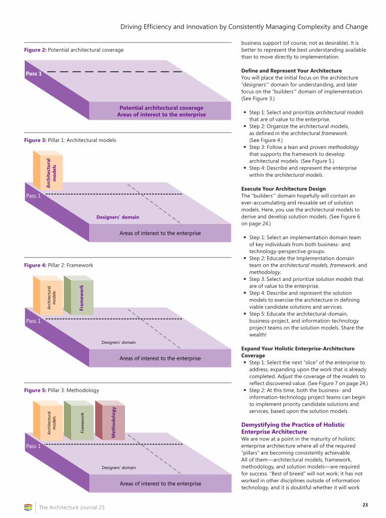
23
Driving Efficiency and Innovation by Consistently Managing Complexity and Change
The Architecture Journal 23
business support (of course, not as desirable). It is better to represent the best understanding available than to move directly to implementation.
Define and Represent Your ArchitectureYou will place the initial focus on the architecture “designers’” domain for understanding, and later focus on the “builders’” domain of implementation. (See Figure 3.)
• Step 1: Select and prioritize architectural models that are of value to the enterprise.
• Step 2: Organize the architectural models, as defined in the architectural framework. (See Figure 4.)
• Step 3: Follow a lean and proven methodology that supports the framework to develop architectural models. (See Figure 5.)
• Step 4: Describe and represent the enterprise within the architectural models.
Execute Your Architecture DesignThe “builders’” domain hopefully will contain an ever-accumulating and reusable set of solution models. Here, you use the architectural models to derive and develop solution models. (See Figure 6 on page 24.)
• Step 1: Select an implementation domain team of key individuals from both business- and technology-perspective groups.
• Step 2: Educate the Implementation domain team on the architectural models, framework, and methodology.
• Step 3: Select and prioritize solution models that are of value to the enterprise.
• Step 4: Describe and represent the solution models to exercise the architecture in defining viable candidate solutions and services.
• Step 5: Educate the architectural-domain, business-project, and information-technology project teams on the solution models. Share the wealth!
Expand Your Holistic Enterprise-Architecture Coverage• Step 1: Select the next “slice” of the enterprise to
address, expanding upon the work that is already completed. Adjust the coverage of the models to reflect discovered value. (See Figure 7 on page 24.)
• Step 2: At this time, both the business- and information-technology project teams can begin to implement priority candidate solutions and services, based upon the solution models.
Demystifying the Practice of Holistic Enterprise ArchitectureWe are now at a point in the maturity of holistic enterprise architecture where all of the required “pillars” are becoming consistently achievable. All of them—architectural models, framework, methodology, and solution models—are required for success. “Best of breed” will not work; it has not worked in other disciplines outside of information technology, and it is doubtful whether it will work
Figure 2: Potential architectural coverage
Pass 1
Potential architectural coverageAreas of interest to the enterprise
Figure 3: Pillar 1: Architectural models
Areas of interest to the enterprise
Pass 1
Arc
hite
ctur
alm
odel
s
Designers’ domain
Figure 4: Pillar 2: Framework
Areas of interest to the enterprise
Designers’ domain
Arch
itect
ural
mod
els
Pass 1
Fram
ework
Figure 5: Pillar 3: Methodology
Areas of interest to the enterprise
Designers’ domain
Arch
itect
ural
mod
els
Fram
ewor
k
Pass 1
Methodology
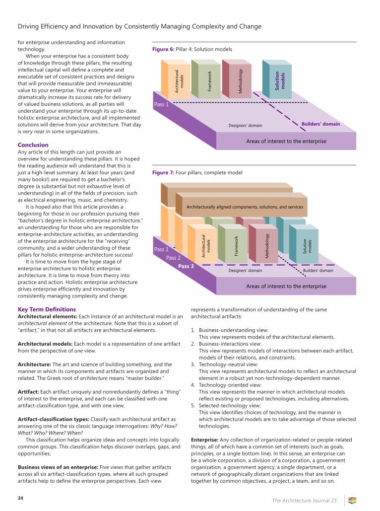
Driving Efficiency and Innovation by Consistently Managing Complexity and Change
The Architecture Journal 2324
for enterprise understanding and information technology.
When your enterprise has a consistent body of knowledge through these pillars, the resulting intellectual capital will define a complete and executable set of consistent practices and designs that will provide measurable (and immeasurable) value to your enterprise. Your enterprise will dramatically increase its success rate for delivery of valued business solutions, as all parties will understand your enterprise through its up-to-date holistic enterprise architecture, and all implemented solutions will derive from your architecture. That day is very near in some organizations.
ConclusionAny article of this length can just provide an overview for understanding these pillars. It is hoped the reading audience will understand that this is just a high-level summary. At least four years (and many books!) are required to get a bachelor’s degree (a substantial but not exhaustive level of understanding) in all of the fields of precision, such as electrical engineering, music, and chemistry.
It is hoped also that this article provides a beginning for those in our profession pursuing their “bachelor’s degree in holistic enterprise architecture,” an understanding for those who are responsible for enterprise-architecture activities, an understanding of the enterprise architecture for the “receiving” community, and a wider understanding of these pillars for holistic enterprise-architecture success!
It is time to move from the hype stage of enterprise architecture to holistic enterprise architecture. It is time to move from theory into practice and action. Holistic enterprise architecture drives enterprise efficiently and innovation by consistently managing complexity and change.
Key Term DefinitionsArchitectural elements: Each instance of an architectural model is an architectural element of the architecture. Note that this is a subset of “artifact,” in that not all artifacts are architectural elements.
Architectural models: Each model is a representation of one artifact from the perspective of one view.
Architecture: The art and science of building something, and the manner in which its components and artifacts are organized and related. The Greek root of architecture means “master builder.”
Artifact: Each artifact uniquely and nonredundantly defines a “thing” of interest to the enterprise, and each can be classified with one artifact-classification type, and with one view.
Artifact-classification types: Classify each architectural artifact as answering one of the six classic language interrogatives: Why? How? What? Who? Where? When?
This classification helps organize ideas and concepts into logically common groups. This classification helps discover overlaps, gaps, and opportunities.
Business views of an enterprise: Five views that gather artifacts across all six artifact-classification types, where all such grouped artifacts help to define the enterprise perspectives. Each view
represents a transformation of understanding of the same architectural artifacts:
1. Business-understanding view:This view represents models of the architectural elements.
2. Business-interactions view:This view represents models of interactions between each artifact, models of their relations, and constraints.
3. Technology-neutral view:This view represents architectural models to reflect an architectural element in a robust yet non-technology-dependent manner.
4. Technology-oriented view:This view represents the manner in which architectural models reflect existing or proposed technologies, including alternatives.
5. Selected-technology view:This view identifies choices of technology, and the manner in which architectural models are to take advantage of those selected technologies.
Enterprise: Any collection of organization-related or people-related things, all of which have a common set of interests (such as goals, principles, or a single bottom line). In this sense, an enterprise can be a whole corporation, a division of a corporation, a government organization, a government agency, a single department, or a network of geographically distant organizations that are linked together by common objectives, a project, a team, and so on.
Figure 6: Pillar 4: Solution models
Areas of interest to the enterprise
Designers’ domain
Arch
itect
ural
mod
els
Fram
ewor
k
Met
hodo
logy
Pass 1
Solu
tion
mod
els
Builders’ domain
Figure 7: Four pillars, complete model
Areas of interest to the enterprise
Arch
itect
ural
Mod
els
Fram
ewor
k
Met
hodo
log
Builders’ domainDesigners’ domain
Arch
itect
ural
Mod
els
Fram
ewor
k
Met
hodo
logy
Arch
itect
ural
mod
els
Fram
ewor
k
Met
hodo
logy
Solu
tion
mod
els
Architecturally aligned components, solutions, and services
Pass 1Pass 2
Pass 3
25
Driving Efficiency and Innovation by Consistently Managing Complexity and Change
The Architecture Journal 23
Enterprise architecture: Enterprise architecture is about understanding the enterprise through:
• A set of independent and nonredundant artifacts.• The interrelations between these artifacts.• Communicating these understandings to the numerous people
who make up the enterprise.
Framework: A logical structure that organizes, for a specific subject, a set of related artifacts, shows the relationships of the artifacts of the chosen subject area, and brings a totality perspective to otherwise individual ideas. A comprehensive framework has a consistent naming of the components and elements of the framework, all terms for the components and elements fully defined, and a consistent and expressive set of graphical representations for each component and element.
Holistic enterprise architecture: An enterprise architecture that is developed and maintained by using the full complement of the four pillars of successful architectures: architecture models, framework, methodology, and solution models.
Interrelations: These are the relationships, interactions, and constraints that individual elements and artifacts have to each other. A reflective relationship is an artifact of one classification type being related to other artifacts of that same type.
Examples of architectural-model reflective interrelations would be a:
• Process (how) relates to another process (how).• Data group (what) relates to another data group (what).
Examples of solution-model nonreflective interrelations would be a(n):
• “Object model”—Data (what) relates to a method (how) relates to an actor (who).
• “Dataflow diagram”—Data (what) relates to a process (how).
Methodology: Consists of practices and procedures that are applied to a specific branch of knowledge.
People: We recognize two primary “types” of people who need to understand the holistic enterprise architecture: business-focused people and technology-focused people.
Solution models: Each solution model is about being able to understand and combine “independent” architectural elements. Each focuses on a single solution description; each is chosen to contribute a given specific entity of business value.
About the AuthorSamuel B. (Sam) Holcman is the Managing Director of the Enterprise Architecture Center of Excellence (EACOE), the Chairman of Pinnacle Business Group, Inc., and the President of the Zachman Institute for Framework Advancement (ZIFA). He is considered the practitioners’ practitioner in enterprise architecture, and a leading implementer of and worldwide educator in enterprise-architecture methodologies and techniques. Sam can be reached via e-mail at [email protected], or via telephone at (810) 231-0531.
Implementation of Microsoft Solution Framework in Distributed Extreme Programmingby Ridi Ferdiana
Microsoft Solution Framework (MSF) is a practical, flexible, and proven approach to delivering software solutions through various artifacts. Frankly speaking, there are two main models in MSF: CMM models and agile models. People will choose the CMM model to provide an enterprise-class software blueprint and the agile model to provide rapid software development. The problem is that many clients want rapid software and need sufficient artifacts. The happy fact is that more than 60 percent of developed software is separated geographically and has limitations in speed and agility.
Distributed extreme programming provides (DXP) a set of methods, process discipline, and certain tools to improve the agility in distributed software development. DXP works by creating a set of mechanisms to implement extreme programming in remote or geographically distributed software development. The key phenomenon of DXP is the way in which communication, coordination, and control happen in distributed software development. The phenomenon is initially solved through various live document artifacts that provide sufficient understanding about the project in distributed software development.
The idea behind this column is to construct an artifact model that mimics how MSF uses artifacts as an indirect communication tool in its phases. DXP has requirements phases, architectural phases, project phases, and product-development phases:
• The artifact in the requirement phase is a user-story artifact, which is just like the persona- and scenario-description artifact in MSF.
• The architectural phase captures solution delivery through a spike-solution artifact, which is just like the functional specification in MSF.
• The project phase captures the planning through an iteration-release planning artifact, which is just like the master project schedule and master project plan in the MSF planning phase.
• The development phase provides development activities through code that comments a lively, test-specification artifact that describes how the testing is done, and a backlog artifact which describes defects in the development system.
Those artifacts work as live documents and work great if they are stored in a collaboration portal such as Windows SharePoint Services (WSS) or Visual Studio Team System (VSTS). The former provides a lightweight portal that is sufficient for small- to medium-size distributed projects, while the latter is great for working in enterprise-class software development.
How sufficient artifacts are composed, what kind of base template is needed, and how it will be implemented is a cool discussion that we can share together at http://ridilabs.net/blog.
Ridi Ferdiana ([email protected]), Microsoft MVP, Gadjah Mada University Lecturer, Indonesia.
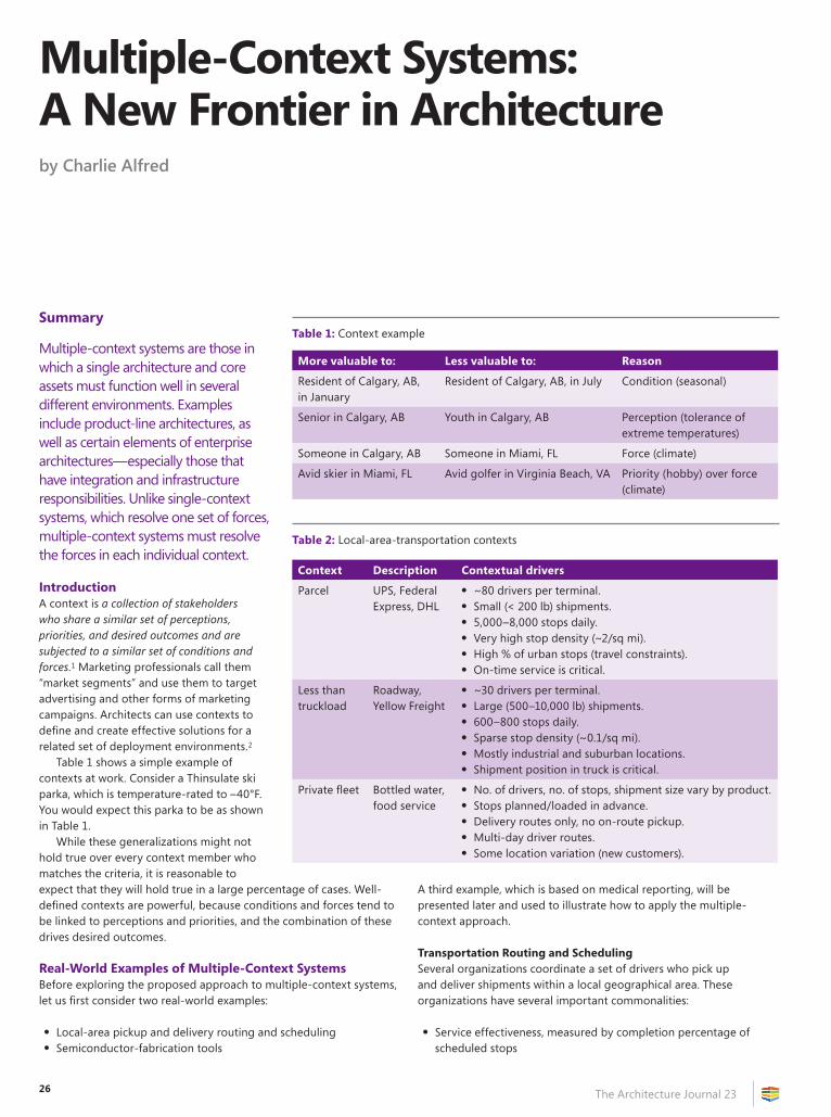
26 The Architecture Journal 23
Summary
Multiple-context systems are those in which a single architecture and core assets must function well in several different environments. Examples include product-line architectures, as well as certain elements of enterprise architectures—especially those that have integration and infrastructure responsibilities. Unlike single-context systems, which resolve one set of forces, multiple-context systems must resolve the forces in each individual context.
IntroductionA context is a collection of stakeholders who share a similar set of perceptions, priorities, and desired outcomes and are subjected to a similar set of conditions and forces.1 Marketing professionals call them “market segments” and use them to target advertising and other forms of marketing campaigns. Architects can use contexts to define and create effective solutions for a related set of deployment environments.2
Table 1 shows a simple example of contexts at work. Consider a Thinsulate ski parka, which is temperature-rated to –40°F. You would expect this parka to be as shown in Table 1.
While these generalizations might not hold true over every context member who matches the criteria, it is reasonable to expect that they will hold true in a large percentage of cases. Well-defined contexts are powerful, because conditions and forces tend to be linked to perceptions and priorities, and the combination of these drives desired outcomes.
Real-World Examples of Multiple-Context SystemsBefore exploring the proposed approach to multiple-context systems, let us first consider two real-world examples:
• Local-area pickup and delivery routing and scheduling• Semiconductor-fabrication tools
A third example, which is based on medical reporting, will be presented later and used to illustrate how to apply the multiple-context approach.
Transportation Routing and SchedulingSeveral organizations coordinate a set of drivers who pick up and deliver shipments within a local geographical area. These organizations have several important commonalities:
• Service effectiveness, measured by completion percentage of scheduled stops
Multiple-Context Systems: A New Frontier in Architectureby Charlie Alfred
Table 1: Context example
More valuable to: Less valuable to: Reason
Resident of Calgary, AB, in January
Resident of Calgary, AB, in July Condition (seasonal)
Senior in Calgary, AB Youth in Calgary, AB Perception (tolerance of extreme temperatures)
Someone in Calgary, AB Someone in Miami, FL Force (climate)
Avid skier in Miami, FL Avid golfer in Virginia Beach, VA Priority (hobby) over force (climate)
Table 2: Local-area-transportation contexts
Context Description Contextual drivers
Parcel UPS, Federal Express, DHL
• ~80 drivers per terminal.• Small (< 200 lb) shipments.• 5,000–8,000 stops daily.• Very high stop density (~2/sq mi).• High % of urban stops (travel constraints).• On-time service is critical.
Less than truckload
Roadway, Yellow Freight
• ~30 drivers per terminal.• Large (500–10,000 lb) shipments.• 600–800 stops daily.• Sparse stop density (~0.1/sq mi).• Mostly industrial and suburban locations.• Shipment position in truck is critical.
Private fleet Bottled water, food service
• No. of drivers, no. of stops, shipment size vary by product.• Stops planned/loaded in advance.• Delivery routes only, no on-route pickup.• Multi-day driver routes.• Some location variation (new customers).
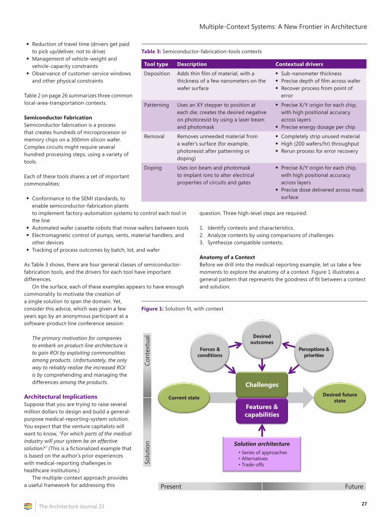
27
Multiple-Context Systems: A New Frontier in Architecture
The Architecture Journal 23
• Reduction of travel time (drivers get paid to pick up/deliver, not to drive)
• Management of vehicle-weight and vehicle-capacity constraints
• Observance of customer-service windows and other physical constraints
Table 2 on page 26 summarizes three common local-area-transportation contexts.
Semiconductor FabricationSemiconductor fabrication is a process that creates hundreds of microprocessor or memory chips on a 300mm silicon wafer. Complex circuits might require several hundred processing steps, using a variety of tools.
Each of these tools shares a set of important commonalities:
• Conformance to the SEMI standards, to enable semiconductor-fabrication plants to implement factory-automation systems to control each tool in the line
• Automated wafer cassette robots that move wafers between tools• Electromagnetic control of pumps, vents, material handlers, and
other devices• Tracking of process outcomes by batch, lot, and wafer
As Table 3 shows, there are four general classes of semiconductor-fabrication tools, and the drivers for each tool have important differences.
On the surface, each of these examples appears to have enough commonality to motivate the creation of a single solution to span the domain. Yet, consider this advice, which was given a few years ago by an anonymous participant at a software-product-line conference session:
The primary motivation for companies to embark on product-line architecture is to gain ROI by exploiting commonalities among products. Unfortunately, the only way to reliably realize the increased ROI is by comprehending and managing the differences among the products.
Architectural ImplicationsSuppose that you are trying to raise several million dollars to design and build a general-purpose medical-reporting-system solution. You expect that the venture capitalists will want to know, “For which parts of the medical industry will your system be an effective solution?” (This is a fictionalized example that is based on the author’s prior experiences with medical-reporting challenges in healthcare institutions.)
The multiple-context approach provides a useful framework for addressing this
question. Three high-level steps are required:
1. Identify contexts and characteristics.2. Analyze contexts by using comparisons of challenges.3. Synthesize compatible contexts.
Anatomy of a ContextBefore we drill into the medical-reporting example, let us take a few moments to explore the anatomy of a context. Figure 1 illustrates a general pattern that represents the goodness of fit between a context and solution.
Figure 1: Solution fit, with context
Challenges
Features & capabilities
Desired future stateCurrent state
Solution architecture• Series of approaches• Alternatives• Trade-offs
Desired outcomes
Perceptions &priorities
Forces & conditions
FuturePresent
Cont
extu
alSo
lutio
n
Table 3: Semiconductor-fabrication-tools contexts
Tool type Description Contextual drivers
Deposition Adds thin film of material, with a thickness of a few nanometers on the wafer surface
• Sub-nanometer thickness• Precise depth of film across wafer• Recover process from point of
error
Patterning Uses an XY stepper to position at each die; creates the desired negative on photoresist by using a laser beam and photomask
• Precise X/Y origin for each chip, with high positional accuracy across layers
• Precise energy dosage per chip
Removal Removes unneeded material from a wafer’s surface (for example, photoresist after patterning or doping)
• Completely strip unused material• High (200 wafers/hr) throughput• Rerun process for error recovery
Doping Uses ion beam and photomask to implant ions to alter electrical properties of circuits and gates
• Precise X/Y origin for each chip, with high positional accuracy across layers
• Precise dose delivered across mask surface
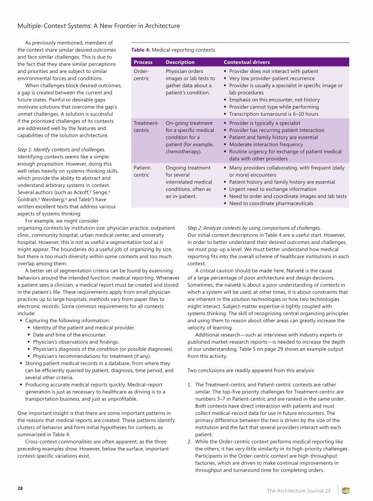
Multiple-Context Systems: A New Frontier in Architecture
The Architecture Journal 2328
As previously mentioned, members of the context share similar desired outcomes and face similar challenges. This is due to the fact that they share similar perceptions and priorities and are subject to similar environmental forces and conditions.
When challenges block desired outcomes, a gap is created between the current and future states. Painful or desirable gaps motivate solutions that overcome the gap’s unmet challenges. A solution is successful if the prioritized challenges of its contexts are addressed well by the features and capabilities of the solution architecture.
Step 1: Identify contexts and challenges.Identifying contexts seems like a simple-enough proposition. However, doing this well relies heavily on systems-thinking skills, which provide the ability to abstract and understand arbitrary systems in context. Several authors (such as Ackoff,3 Senge,4 Goldratt,5 Weinberg,6 and Taleb7) have written excellent texts that address various aspects of systems thinking
For example, we might consider organizing contexts by institution size: physician practice, outpatient clinic, community hospital, urban medical center, and university hospital. However, this is not as useful a segmentation tool as it might appear. The boundaries do a useful job of organizing by size, but there is too much diversity within some contexts and too much overlap among them.
A better set of segmentation criteria can be found by examining behaviors around the intended function: medical reporting. Whenever a patient sees a clinician, a medical report must be created and stored in the patient’s file. These requirements apply from small physician practices up to large hospitals; methods vary from paper files to electronic records. Some common requirements for all contexts include:• Capturing the following information:
• Identity of the patient and medical provider.• Date and time of the encounter.• Physician’s observations and findings.• Physician’s diagnosis of the condition (or possible diagnoses).• Physician’s recommendations for treatment (if any).
• Storing patient medical records in a database, from where they can be efficiently queried by patient, diagnosis, time period, and several other criteria.
• Producing accurate medical reports quickly. Medical-report generation is just as necessary to healthcare as driving is to a transportation business, and just as unprofitable.
One important insight is that there are some important patterns in the reasons that medical reports are created. These patterns identify clusters of behavior and form initial hypotheses for contexts, as summarized in Table 4.
Cross-context commonalities are often apparent, as the three preceding examples show. However, below the surface, important context-specific variations exist.
Step 2: Analyze contexts by using comparisons of challenges.Our initial context descriptions in Table 4 are a useful start. However, in order to better understand their desired outcomes and challenges, we must pop-up a level. We must better understand how medical reporting fits into the overall scheme of healthcare institutions in each context.
A critical caution should be made here. Naïveté is the cause of a large percentage of poor architecture and design decisions. Sometimes, the naïveté is about a poor understanding of contexts in which a system will be used; at other times, it is about constraints that are inherent in the solution technologies or how two technologies might interact. Subject-matter expertise is tightly coupled with systems thinking. The skill of recognizing central organizing principles and using them to reason about other areas can greatly increase the velocity of learning.
Additional research—such as interviews with industry experts or published market-research reports—is needed to increase the depth of our understanding. Table 5 on page 29 shows an example output from this activity.
Two conclusions are readily apparent from this analysis:
1. The Treatment-centric and Patient-centric contexts are rather similar. The top-five priority challenges for Treatment-centric are numbers 3–7 in Patient-centric and are ranked in the same order. Both contexts have direct interaction with patients and must collect medical-record data for use in future encounters. The primary difference between the two is driven by the size of the institution and the fact that several providers interact with each patient.
2. While the Order-centric context performs medical reporting like the others, it has very little similarity in its high-priority challenges. Participants in the Order-centric context are high-throughput factories, which are driven to make continual improvements in throughput and turnaround time for completing orders.
Table 4: Medical-reporting contexts
Process Description Contextual drivers
Order-centric
Physician orders images or lab tests to gather data about a patient’s condition.
• Provider does not interact with patient• Very low provider-patient recurrence• Provider is usually a specialist in specific image or
lab procedures• Emphasis on this encounter, not history• Provider cannot type while performing• Transcription turnaround is 6–10 hours
Treatment-centric
On-going treatment for a specific medical condition for a patient (for example, chemotherapy).
• Provider is typically a specialist• Provider has recurring patient interaction• Patient and family history are essential• Moderate interaction frequency• Routine urgency for exchange of patient medical
data with other providers
Patient-centric
Ongoing treatment for several interrelated medical conditions, often as an in-patient.
• Many providers collaborating, with frequent (daily or more) encounters
• Patient history and family history are essential• Urgent need to exchange information• Need to order and coordinate images and lab tests• Need to coordinate pharmaceuticals
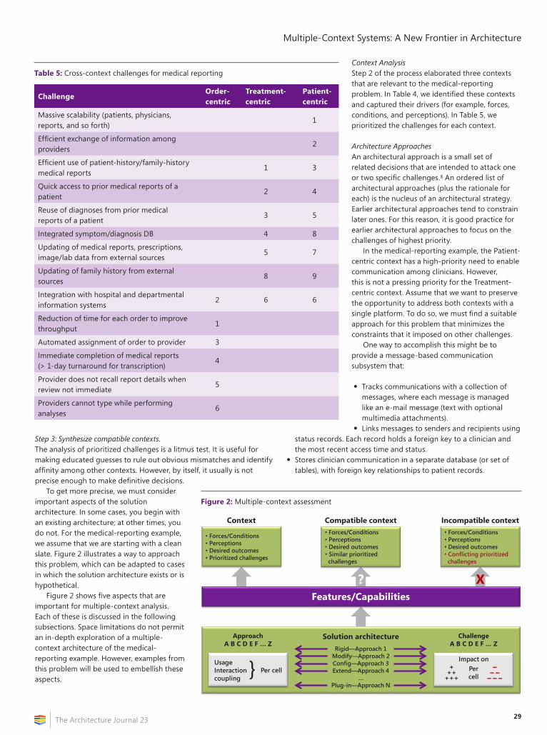
29
Multiple-Context Systems: A New Frontier in Architecture
The Architecture Journal 23
Step 3: Synthesize compatible contexts.The analysis of prioritized challenges is a litmus test. It is useful for making educated guesses to rule out obvious mismatches and identify affinity among other contexts. However, by itself, it usually is not precise enough to make definitive decisions.
To get more precise, we must consider important aspects of the solution architecture. In some cases, you begin with an existing architecture; at other times, you do not. For the medical-reporting example, we assume that we are starting with a clean slate. Figure 2 illustrates a way to approach this problem, which can be adapted to cases in which the solution architecture exists or is hypothetical.
Figure 2 shows five aspects that are important for multiple-context analysis. Each of these is discussed in the following subsections. Space limitations do not permit an in-depth exploration of a multiple-context architecture of the medical-reporting example. However, examples from this problem will be used to embellish these aspects.
Context AnalysisStep 2 of the process elaborated three contexts that are relevant to the medical-reporting problem. In Table 4, we identified these contexts and captured their drivers (for example, forces, conditions, and perceptions). In Table 5, we prioritized the challenges for each context.
Architecture ApproachesAn architectural approach is a small set of related decisions that are intended to attack one or two specific challenges.8 An ordered list of architectural approaches (plus the rationale for each) is the nucleus of an architectural strategy. Earlier architectural approaches tend to constrain later ones. For this reason, it is good practice for earlier architectural approaches to focus on the challenges of highest priority.
In the medical-reporting example, the Patient-centric context has a high-priority need to enable communication among clinicians. However, this is not a pressing priority for the Treatment-centric context. Assume that we want to preserve the opportunity to address both contexts with a single platform. To do so, we must find a suitable approach for this problem that minimizes the constraints that it imposed on other challenges.
One way to accomplish this might be to provide a message-based communication subsystem that:
• Tracks communications with a collection of messages, where each message is managed like an e-mail message (text with optional multimedia attachments).
• Links messages to senders and recipients using
Figure 2: Multiple-context assessment
? X
• Forces/Conditions• Perceptions• Desired outcomes• Prioritized challenges
Features/Capabilities
• Forces/Conditions• Perceptions• Desired outcomes• Similar prioritized challenges
• Forces/Conditions• Perceptions• Desired outcomes• Conflicting prioritized challenges
Context Compatible context Incompatible context
Solution architectureApproachA B C D E F … Z
ChallengeA B C D E F … Z
UsageInteractioncoupling
} Per cell +++
+++
Impact onPercell
–– –– – –
Rigid—Approach 1Modify—Approach 2Config—Approach 3Extend—Approach 4
…Plug-in—Approach N
Table 5: Cross-context challenges for medical reporting
ChallengeOrder-centric
Treatment-centric
Patient-centric
Massive scalability (patients, physicians, reports, and so forth)
1
Efficient exchange of information among providers
2
Efficient use of patient-history/family-history medical reports
1 3
Quick access to prior medical reports of a patient
2 4
Reuse of diagnoses from prior medical reports of a patient
3 5
Integrated symptom/diagnosis DB 4 8
Updating of medical reports, prescriptions, image/lab data from external sources
5 7
Updating of family history from external sources
8 9
Integration with hospital and departmental information systems
2 6 6
Reduction of time for each order to improve throughput
1
Automated assignment of order to provider 3
Immediate completion of medical reports (> 1-day turnaround for transcription)
4
Provider does not recall report details when review not immediate
5
Providers cannot type while performing analyses
6
status records. Each record holds a foreign key to a clinician and the most recent access time and status.
• Stores clinician communication in a separate database (or set of tables), with foreign key relationships to patient records.
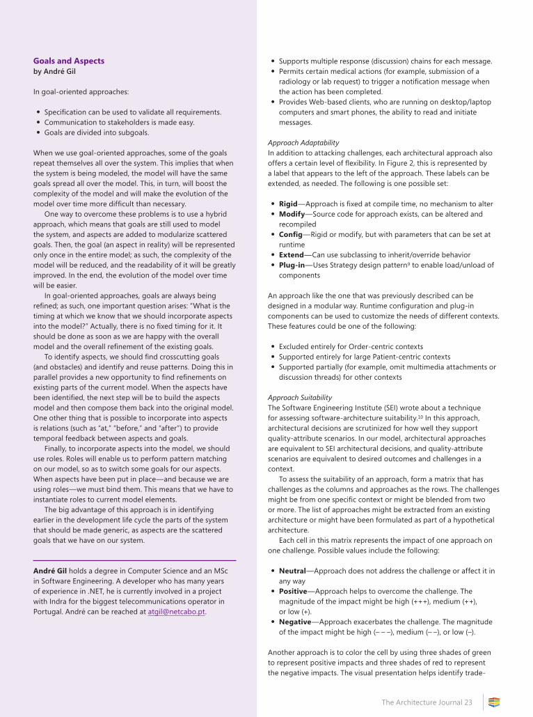
The Architecture Journal 2330
• Supports multiple response (discussion) chains for each message.• Permits certain medical actions (for example, submission of a
radiology or lab request) to trigger a notification message when the action has been completed.
• Provides Web-based clients, who are running on desktop/laptop computers and smart phones, the ability to read and initiate messages.
Approach AdaptabilityIn addition to attacking challenges, each architectural approach also offers a certain level of flexibility. In Figure 2, this is represented by a label that appears to the left of the approach. These labels can be extended, as needed. The following is one possible set:
• Rigid—Approach is fixed at compile time, no mechanism to alter• Modify—Source code for approach exists, can be altered and
recompiled• Config—Rigid or modify, but with parameters that can be set at
runtime• Extend—Can use subclassing to inherit/override behavior• Plug-in—Uses Strategy design pattern9 to enable load/unload of
components
An approach like the one that was previously described can be designed in a modular way. Runtime configuration and plug-in components can be used to customize the needs of different contexts. These features could be one of the following:
• Excluded entirely for Order-centric contexts• Supported entirely for large Patient-centric contexts• Supported partially (for example, omit multimedia attachments or
discussion threads) for other contexts
Approach SuitabilityThe Software Engineering Institute (SEI) wrote about a technique for assessing software-architecture suitability.10 In this approach, architectural decisions are scrutinized for how well they support quality-attribute scenarios. In our model, architectural approaches are equivalent to SEI architectural decisions, and quality-attribute scenarios are equivalent to desired outcomes and challenges in a context.
To assess the suitability of an approach, form a matrix that has challenges as the columns and approaches as the rows. The challenges might be from one specific context or might be blended from two or more. The list of approaches might be extracted from an existing architecture or might have been formulated as part of a hypothetical architecture.
Each cell in this matrix represents the impact of one approach on one challenge. Possible values include the following:
• Neutral—Approach does not address the challenge or affect it in any way
• Positive—Approach helps to overcome the challenge. The magnitude of the impact might be high (+++), medium (++), or low (+).
• Negative—Approach exacerbates the challenge. The magnitude of the impact might be high (– – –), medium (– –), or low (–).
Another approach is to color the cell by using three shades of green to represent positive impacts and three shades of red to represent the negative impacts. The visual presentation helps identify trade-
Goals and Aspectsby André Gil
In goal-oriented approaches:
• Specification can be used to validate all requirements.• Communication to stakeholders is made easy.• Goals are divided into subgoals.
When we use goal-oriented approaches, some of the goals repeat themselves all over the system. This implies that when the system is being modeled, the model will have the same goals spread all over the model. This, in turn, will boost the complexity of the model and will make the evolution of the model over time more difficult than necessary.
One way to overcome these problems is to use a hybrid approach, which means that goals are still used to model the system, and aspects are added to modularize scattered goals. Then, the goal (an aspect in reality) will be represented only once in the entire model; as such, the complexity of the model will be reduced, and the readability of it will be greatly improved. In the end, the evolution of the model over time will be easier.
In goal-oriented approaches, goals are always being refined; as such, one important question arises: “What is the timing at which we know that we should incorporate aspects into the model?” Actually, there is no fixed timing for it. It should be done as soon as we are happy with the overall model and the overall refinement of the existing goals.
To identify aspects, we should find crosscutting goals (and obstacles) and identify and reuse patterns. Doing this in parallel provides a new opportunity to find refinements on existing parts of the current model. When the aspects have been identified, the next step will be to build the aspects model and then compose them back into the original model. One other thing that is possible to incorporate into aspects is relations (such as “at,” “before,” and “after”) to provide temporal feedback between aspects and goals.
Finally, to incorporate aspects into the model, we should use roles. Roles will enable us to perform pattern matching on our model, so as to switch some goals for our aspects. When aspects have been put in place—and because we are using roles—we must bind them. This means that we have to instantiate roles to current model elements.
The big advantage of this approach is in identifying earlier in the development life cycle the parts of the system that should be made generic, as aspects are the scattered goals that we have on our system.
André Gil holds a degree in Computer Science and an MSc in Software Engineering. A developer who has many years of experience in .NET, he is currently involved in a project with Indra for the biggest telecommunications operator in Portugal. André can be reached at [email protected].
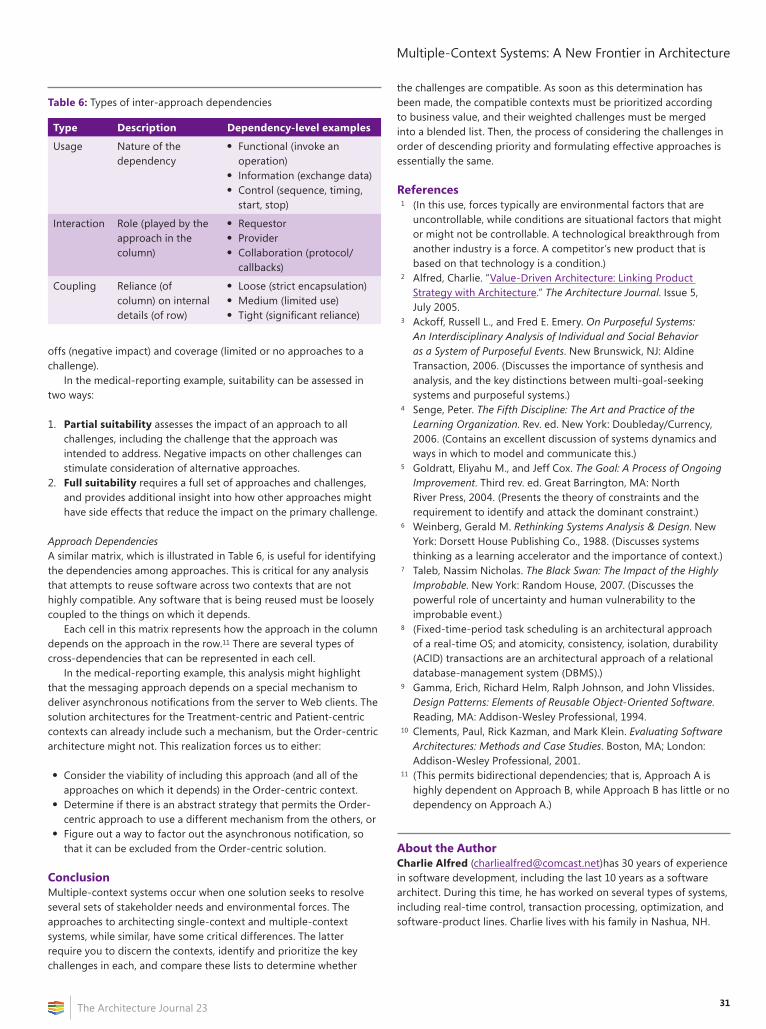
31
Multiple-Context Systems: A New Frontier in Architecture
The Architecture Journal 23
offs (negative impact) and coverage (limited or no approaches to a challenge).
In the medical-reporting example, suitability can be assessed in two ways:
1. Partial suitability assesses the impact of an approach to all challenges, including the challenge that the approach was intended to address. Negative impacts on other challenges can stimulate consideration of alternative approaches.
2. Full suitability requires a full set of approaches and challenges, and provides additional insight into how other approaches might have side effects that reduce the impact on the primary challenge.
Approach DependenciesA similar matrix, which is illustrated in Table 6, is useful for identifying the dependencies among approaches. This is critical for any analysis that attempts to reuse software across two contexts that are not highly compatible. Any software that is being reused must be loosely coupled to the things on which it depends.
Each cell in this matrix represents how the approach in the column depends on the approach in the row.11 There are several types of cross-dependencies that can be represented in each cell.
In the medical-reporting example, this analysis might highlight that the messaging approach depends on a special mechanism to deliver asynchronous notifications from the server to Web clients. The solution architectures for the Treatment-centric and Patient-centric contexts can already include such a mechanism, but the Order-centric architecture might not. This realization forces us to either:
• Consider the viability of including this approach (and all of the approaches on which it depends) in the Order-centric context.
• Determine if there is an abstract strategy that permits the Order-centric approach to use a different mechanism from the others, or
• Figure out a way to factor out the asynchronous notification, so that it can be excluded from the Order-centric solution.
ConclusionMultiple-context systems occur when one solution seeks to resolve several sets of stakeholder needs and environmental forces. The approaches to architecting single-context and multiple-context systems, while similar, have some critical differences. The latter require you to discern the contexts, identify and prioritize the key challenges in each, and compare these lists to determine whether
the challenges are compatible. As soon as this determination has been made, the compatible contexts must be prioritized according to business value, and their weighted challenges must be merged into a blended list. Then, the process of considering the challenges in order of descending priority and formulating effective approaches is essentially the same.
References1 (In this use, forces typically are environmental factors that are
uncontrollable, while conditions are situational factors that might or might not be controllable. A technological breakthrough from another industry is a force. A competitor’s new product that is based on that technology is a condition.)
2 Alfred, Charlie. “Value-Driven Architecture: Linking Product Strategy with Architecture.” The Architecture Journal. Issue 5, July 2005.
3 Ackoff, Russell L., and Fred E. Emery. On Purposeful Systems: An Interdisciplinary Analysis of Individual and Social Behavior as a System of Purposeful Events. New Brunswick, NJ: Aldine Transaction, 2006. (Discusses the importance of synthesis and analysis, and the key distinctions between multi-goal-seeking systems and purposeful systems.)
4 Senge, Peter. The Fifth Discipline: The Art and Practice of the Learning Organization. Rev. ed. New York: Doubleday/Currency, 2006. (Contains an excellent discussion of systems dynamics and ways in which to model and communicate this.)
5 Goldratt, Eliyahu M., and Jeff Cox. The Goal: A Process of Ongoing Improvement. Third rev. ed. Great Barrington, MA: North River Press, 2004. (Presents the theory of constraints and the requirement to identify and attack the dominant constraint.)
6 Weinberg, Gerald M. Rethinking Systems Analysis & Design. New York: Dorsett House Publishing Co., 1988. (Discusses systems thinking as a learning accelerator and the importance of context.)
7 Taleb, Nassim Nicholas. The Black Swan: The Impact of the Highly Improbable. New York: Random House, 2007. (Discusses the powerful role of uncertainty and human vulnerability to the improbable event.)
8 (Fixed-time-period task scheduling is an architectural approach of a real-time OS; and atomicity, consistency, isolation, durability (ACID) transactions are an architectural approach of a relational database-management system (DBMS).)
9 Gamma, Erich, Richard Helm, Ralph Johnson, and John Vlissides. Design Patterns: Elements of Reusable Object-Oriented Software. Reading, MA: Addison-Wesley Professional, 1994.
10 Clements, Paul, Rick Kazman, and Mark Klein. Evaluating Software Architectures: Methods and Case Studies. Boston, MA; London: Addison-Wesley Professional, 2001.
11 (This permits bidirectional dependencies; that is, Approach A is highly dependent on Approach B, while Approach B has little or no dependency on Approach A.)
About the AuthorCharlie Alfred ([email protected])has 30 years of experience in software development, including the last 10 years as a software architect. During this time, he has worked on several types of systems, including real-time control, transaction processing, optimization, and software-product lines. Charlie lives with his family in Nashua, NH.
Table 6: Types of inter-approach dependencies
Type Description Dependency-level examples
Usage Nature of the dependency
• Functional (invoke an operation)
• Information (exchange data)• Control (sequence, timing,
start, stop)
Interaction Role (played by the approach in the column)
• Requestor• Provider• Collaboration (protocol/
callbacks)
Coupling Reliance (of column) on internal details (of row)
• Loose (strict encapsulation)• Medium (limited use)• Tight (significant reliance)
32 The Architecture Journal 23
Summary
This article describes the scenarios in which UML or DSLs should be used, and how each can be effectively integrated with the other.
IntroductionThe release of Microsoft Visual Studio 2010 Ultimate marks the first time that architects will have a set of UML and DSL modeling tools in the same development environment. While the concepts of UML and DSL modeling have been around for a long time, this is the first tool release that effectively combines them in one product and enables rich integration among multiple models.
Yet, it was not long after the new UML capabilities were announced that a debate ensued over which modeling tool is superior. This debate, however, is perhaps as meaningful as a humorous scene from the US television program The Office:
Jim Halpert: “Question. What kind of bear is best?”Dwight Schrute: “That’s a ridiculous question.”JH: “False. Black bear.”DS: “That’s debatable. There are basically two schools of thought...”JH: “Fact. Bears eat beets. Bears. Beets. Battlestar Galactica.”DS: “Bears do not... What is going on?! What are you doing?!”
A debate about what is the “best bear” is meaningless. Along the same lines, this article will show that there is no “best” between UML and DSL. Just as the polar bear and the black bear are both best-suited for their particular environments, so, too, do UML and DSL have their unique strengths towards a particular problem space.
This article will not try to state which tool is “best”; instead, it will describe the scenarios in which UML or DSLs should be used, and how each can be effectively integrated with the other.
Where Is UML at Microsoft?Just about every software architect and developer has at least some familiarity with the Unified Modeling Language (UML). Created by Rumbaugh, Booch, and Jacobsen as a means to hasten the adoption for object-oriented technologies, UML 1.1 was proposed to and accepted by the OMG in 1997. Since that time, UML has evolved into its current form of version 2.2. Yet, for these past 12 to 13 years, developers and architects who work within the Microsoft suite of tools were resigned to call upon Microsoft Visio or third-party software to try to reap the rewards that the uniformity of UML promised. The lack of UML tooling and support in Microsoft’s main development
environment, Visual Studio, has been a void that many architects and developers have long wished was filled.
Instead, Microsoft provided a rich authoring environment for graphical domain-specific languages when it released the Domain-Specific Language (DSL) Tools capability with Visual Studio 2005. The Visual Studio 2010 Ultimate release adds—among other things—the ability to have DSL diagrams interact with each other and with UML diagrams. It also adds UML 2.x–compliant (or “logical”) class, component, activity, sequence, and use-case diagrams.
Keen observers might be quick to point out that this is not a complete list of UML 2.x diagrams. UML 2.2 defines 14 types of diagrams, 7 of which are a type of structure diagram (such as the class and component diagrams) and 7 of which are a type of behavior diagram (such as the activity, sequence, and use-case diagrams). However, the included diagrams cover the most used features of UML, and the underlying modeling framework allows for the dynamic addition of more diagrams with a later release, service pack, or power tool.
Which Modeling Technique Should I Use?Using Visual Studio, architects have been creating custom visual designers that are specific to particular domains and generating code and other artifacts from them since DSL Tools was introduced. Until now, however, if a custom designer were needed to help model a particular domain, there was not much choice; DSL Tools was the only way to go. Even if they just wanted a state diagram with a code generator, they had to create a custom DSL. Some customers were reinventing UML-like designers by using DSL Tools.
Now, however, with the introduction of the UML diagrams—and the flexibility to not only extend the design surface for them, but also to generate artifacts from them—should we infer that Microsoft will no longer be encouraging development of custom DSLs? Should focus be moved from developing custom DSLs to extending the UML diagrams that ship with Visual Studio? After all, the great thing about the introduction of these new UML features is that it opens up new possibilities; it allows for the creation of models and artifacts that were, at best, nontrivial to create in the past. But with these new possibilities comes the need to make a choice. When should we extend the capabilities that are provided with the UML designers, and when should we look to create entirely new DSLs?
For architects, Table 1 on page 33 describes the essential differences between the two approaches.
If architects want to specify the usage of their modeling tools by development teams, the comparison is different. This might happen if the architect has defined a standard architecture that is to be followed by development teams and the architect wants them to create models
UML or DSL: Which Bear Is Best?by Len Fenster and Brooke Hamilton
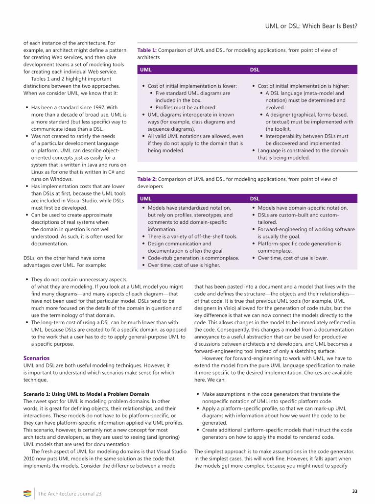
33
UML or DSL: Which Bear Is Best?
The Architecture Journal 23
of each instance of the architecture. For example, an architect might define a pattern for creating Web services, and then give development teams a set of modeling tools for creating each individual Web service.
Tables 1 and 2 highlight important distinctions between the two approaches. When we consider UML, we know that it:
• Has been a standard since 1997. With more than a decade of broad use, UML is a more standard (but less specific) way to communicate ideas than a DSL.
• Was not created to satisfy the needs of a particular development language or platform. UML can describe object-oriented concepts just as easily for a system that is written in Java and runs on Linux as for one that is written in C# and runs on Windows.
• Has implementation costs that are lower than DSLs at first, because the UML tools are included in Visual Studio, while DSLs must first be developed.
• Can be used to create approximate descriptions of real systems when the domain in question is not well understood. As such, it is often used for documentation.
DSLs, on the other hand have some advantages over UML. For example:
• They do not contain unnecessary aspects of what they are modeling. If you look at a UML model you might find many diagrams—and many aspects of each diagram—that have not been used for that particular model. DSLs tend to be much more focused on the details of the domain in question and use the terminology of that domain.
• The long-term cost of using a DSL can be much lower than with UML, because DSLs are created to fit a specific domain, as opposed to the work that a user has to do to apply general-purpose UML to a specific purpose.
ScenariosUML and DSL are both useful modeling techniques. However, it is important to understand which scenarios make sense for which technique.
Scenario 1: Using UML to Model a Problem DomainThe sweet spot for UML is modeling problem domains. In other words, it is great for defining objects, their relationships, and their interactions. These models do not have to be platform-specific, or they can have platform-specific information applied via UML profiles. This scenario, however, is certainly not a new concept for most architects and developers, as they are used to seeing (and ignoring) UML models that are used for documentation.
The fresh aspect of UML for modeling domains is that Visual Studio 2010 now puts UML models in the same solution as the code that implements the models. Consider the difference between a model
that has been pasted into a document and a model that lives with the code and defines the structure—the objects and their relationships—of that code. It is true that previous UML tools (for example, UML designers in Visio) allowed for the generation of code stubs, but the key difference is that we can now connect the models directly to the code. This allows changes in the model to be immediately reflected in the code. Consequently, this changes a model from a documentation annoyance to a useful abstraction that can be used for productive discussions between architects and developers, and UML becomes a forward-engineering tool instead of only a sketching surface.
However, for forward-engineering to work with UML, we have to extend the model from the pure UML language specification to make it more specific to the desired implementation. Choices are available here. We can:
• Make assumptions in the code generators that translate the nonspecific notation of UML into specific platform code.
• Apply a platform-specific profile, so that we can mark-up UML diagrams with information about how we want the code to be generated.
• Create additional platform-specific models that instruct the code generators on how to apply the model to rendered code.
The simplest approach is to make assumptions in the code generator. In the simplest cases, this will work fine. However, it falls apart when the models get more complex, because you might need to specify
Table 1: Comparison of UML and DSL for modeling applications, from point of view of architects
UML DSL
• Cost of initial implementation is lower:• Five standard UML diagrams are
included in the box.• Profiles must be authored.
• UML diagrams interoperate in known ways (for example, class diagrams and sequence diagrams).
• All valid UML notations are allowed, even if they do not apply to the domain that is being modeled.
• Cost of initial implementation is higher:• A DSL language (meta-model and
notation) must be determined and evolved.
• A designer (graphical, forms-based, or textual) must be implemented with the toolkit.
• Interoperability between DSLs must be discovered and implemented.
• Language is constrained to the domain that is being modeled.
Table 2: Comparison of UML and DSL for modeling applications, from point of view of developers
UML DSL
• Models have standardized notation, but rely on profiles, stereotypes, and comments to add domain-specific information.
• There is a variety of off-the-shelf tools.• Design communication and
documentation is often the goal.• Code-stub generation is commonplace.• Over time, cost of use is higher.
• Models have domain-specific notation.• DSLs are custom-built and custom-
tailored.• Forward-engineering of working software
is usually the goal.• Platform-specific code generation is
commonplace.• Over time, cost of use is lower.
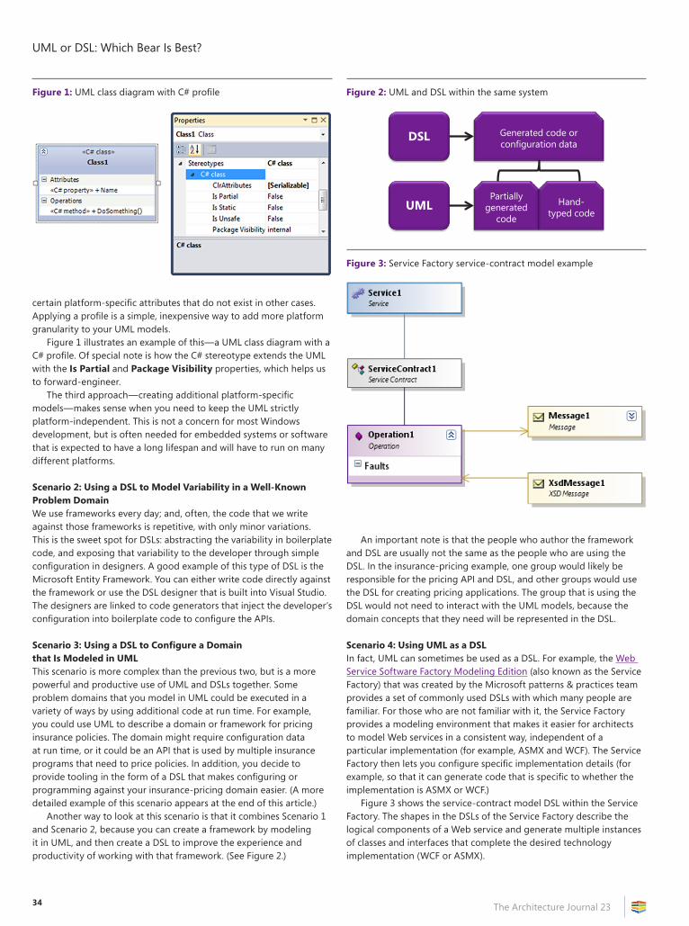
UML or DSL: Which Bear Is Best?
The Architecture Journal 2334
certain platform-specific attributes that do not exist in other cases. Applying a profile is a simple, inexpensive way to add more platform granularity to your UML models.
Figure 1 illustrates an example of this—a UML class diagram with a C# profile. Of special note is how the C# stereotype extends the UML with the Is Partial and Package Visibility properties, which helps us to forward-engineer.
The third approach—creating additional platform-specific models—makes sense when you need to keep the UML strictly platform-independent. This is not a concern for most Windows development, but is often needed for embedded systems or software that is expected to have a long lifespan and will have to run on many different platforms.
Scenario 2: Using a DSL to Model Variability in a Well-Known Problem DomainWe use frameworks every day; and, often, the code that we write against those frameworks is repetitive, with only minor variations. This is the sweet spot for DSLs: abstracting the variability in boilerplate code, and exposing that variability to the developer through simple configuration in designers. A good example of this type of DSL is the Microsoft Entity Framework. You can either write code directly against the framework or use the DSL designer that is built into Visual Studio. The designers are linked to code generators that inject the developer’s configuration into boilerplate code to configure the APIs.
Scenario 3: Using a DSL to Configure a Domain that Is Modeled in UMLThis scenario is more complex than the previous two, but is a more powerful and productive use of UML and DSLs together. Some problem domains that you model in UML could be executed in a variety of ways by using additional code at run time. For example, you could use UML to describe a domain or framework for pricing insurance policies. The domain might require configuration data at run time, or it could be an API that is used by multiple insurance programs that need to price policies. In addition, you decide to provide tooling in the form of a DSL that makes configuring or programming against your insurance-pricing domain easier. (A more detailed example of this scenario appears at the end of this article.)
Another way to look at this scenario is that it combines Scenario 1 and Scenario 2, because you can create a framework by modeling it in UML, and then create a DSL to improve the experience and productivity of working with that framework. (See Figure 2.)
An important note is that the people who author the framework and DSL are usually not the same as the people who are using the DSL. In the insurance-pricing example, one group would likely be responsible for the pricing API and DSL, and other groups would use the DSL for creating pricing applications. The group that is using the DSL would not need to interact with the UML models, because the domain concepts that they need will be represented in the DSL.
Scenario 4: Using UML as a DSLIn fact, UML can sometimes be used as a DSL. For example, the Web Service Software Factory Modeling Edition (also known as the Service Factory) that was created by the Microsoft patterns & practices team provides a set of commonly used DSLs with which many people are familiar. For those who are not familiar with it, the Service Factory provides a modeling environment that makes it easier for architects to model Web services in a consistent way, independent of a particular implementation (for example, ASMX and WCF). The Service Factory then lets you configure specific implementation details (for example, so that it can generate code that is specific to whether the implementation is ASMX or WCF.)
Figure 3 shows the service-contract model DSL within the Service Factory. The shapes in the DSLs of the Service Factory describe the logical components of a Web service and generate multiple instances of classes and interfaces that complete the desired technology implementation (WCF or ASMX).
Figure 1: UML class diagram with C# profile Figure 2: UML and DSL within the same system
DSL
UML
Generated code or configuration data
Partially generated
code
Hand-typed code
Figure 3: Service Factory service-contract model example
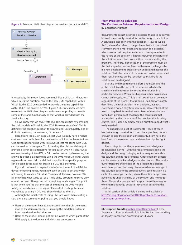
35
UML or DSL: Which Bear Is Best?
The Architecture Journal 23
Interestingly, this model looks very much like a UML class diagram—which raises the question, “Could the new UML capabilities within Visual Studio 2010 be extended to provide the same capabilities as this DSL?” The answer is, “Yes.” Figure 4 illustrates how we have extended the UML class diagram with a custom profile, to provide some of the same functionality as that which is provided with the Service Factory.
So, we know that we can create DSL-like capabilities by extending the UML models in Visual Studio 2010. However, should we? This is definitely the tougher question to answer; and, unfortunately, like all difficult questions, the answer is, “It depends.”
Recall from Table 1 on page 33 that DSLs typically have a higher cost associated with them for the creation of initial implementations. One advantage for using UML like a DSL is that modeling with UML can be used to prototype a DSL. Extending the UML models might provide a lower-cost alternative for you. Later, when it is clear what elements must go into a DSL, a DSL can be created by harvesting the knowledge that is gained while using the UML model. In other words, a general-purpose UML model that is applied to a specific purpose can be used as the basis for creating a DSL at a later time.
If you do not need to expend a lot of effort to mold the UML to fit your modeling needs, you might even be able to get away with not having to create a DSL at all. Tread carefully here, however. We all know that what starts out as a “little utility program” to serve only a small purpose often grows into something much larger. The point is that when you see that the cost of extending the UML models to fit your needs exceeds or equals the cost of creating the same capabilities by using a DSL, you should switch to the DSL.
Although the initial costs of using UML are lower than creating a DSL, there are some other points that you should know:
• Users of the models have to understand how the UML elements map to the domain concepts—making the models less clear in how they describe their domain.
• Users of the models also might not be aware of which parts of the UML apply to the domain and which are unnecessary.
Figure 4: Extended UML class diagram as service-contract model DSLFrom Problem to Solution: The Continuum Between Requirements and Designby Christopher Brandt
Requirements do not describe a problem that is to be solved; instead, they specify constraints on the design of a solution. A solution is one answer to the question, “How do we do this?”, where this refers to the problem that is to be solved. Normally, there is more than one solution to a problem, which means that requirements cannot be captured until the nature of the solution is known. However, the nature of the solution cannot be known without understanding the problem. Therefore, identification of the problem must be the first step when we are faced with a new challenge—be it a new development project or an undesigned aspect of a solution. Next, the nature of the solution can be determined; then, requirements can be specified, so that finally the solution can be designed.
Starting with requirements before understanding the problem will bias the form of the solution, which kills creativity and innovation by forcing the solution in a particular direction. When this happens, other possibilities cannot be investigated. This is a mistake that can be made, regardless of the process that is being used. Unfortunately, describing the root problem in an unbiased, abstract statement is not an easy task; it requires all members of the team to step back from their own biases of the solution’s form. Each person must challenge the constraints that are implied by the statement of the problem that is being crafted. This is done by simply asking questions about what is really needed.
The endgame is a set of statements—each of which has just enough constraints to describe a problem, but not enough to bias the solution unnecessarily. From here, the best form of the solution can be determined by the right people.
From this point on, the requirements and design can be advanced in sync—with the requirements feeding the design and the design bringing out more questions about the solution and its requirements. A development process can be viewed as a knowledge-transfer process. The product owner transfers knowledge of the problem to a design team. In response, the design team transfers knowledge of the solution back to the product owner. Each iteration is a cycle of knowledge transfer, where the entire design team advances its understanding of the solution and how it got there. The product owner and designers must have a good working relationship, because they are all designing the solution.
A full version of this article is online and available at http://xb-log.blogspot.com/2010/01/problem-to-solution-continuum-between.html.
Christopher Brandt ([email protected]) is the Systems Architect at Moneris Solutions. He has been working on loyalty-transaction processing for 11 years.
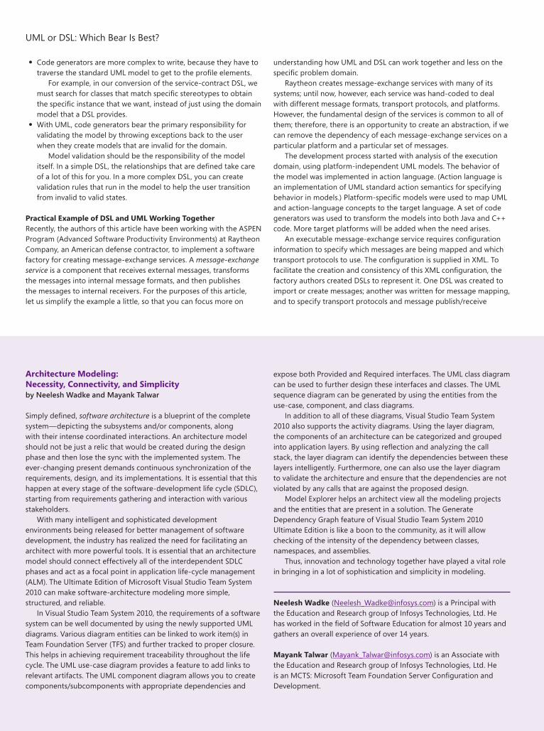
UML or DSL: Which Bear Is Best?
The Architecture Journal 2336
• Code generators are more complex to write, because they have to traverse the standard UML model to get to the profile elements.
For example, in our conversion of the service-contract DSL, we must search for classes that match specific stereotypes to obtain the specific instance that we want, instead of just using the domain model that a DSL provides.
• With UML, code generators bear the primary responsibility for validating the model by throwing exceptions back to the user when they create models that are invalid for the domain.
Model validation should be the responsibility of the model itself. In a simple DSL, the relationships that are defined take care of a lot of this for you. In a more complex DSL, you can create validation rules that run in the model to help the user transition from invalid to valid states.
Practical Example of DSL and UML Working TogetherRecently, the authors of this article have been working with the ASPEN Program (Advanced Software Productivity Environments) at Raytheon Company, an American defense contractor, to implement a software factory for creating message-exchange services. A message-exchange service is a component that receives external messages, transforms the messages into internal message formats, and then publishes the messages to internal receivers. For the purposes of this article, let us simplify the example a little, so that you can focus more on
understanding how UML and DSL can work together and less on the specific problem domain.
Raytheon creates message-exchange services with many of its systems; until now, however, each service was hand-coded to deal with different message formats, transport protocols, and platforms. However, the fundamental design of the services is common to all of them; therefore, there is an opportunity to create an abstraction, if we can remove the dependency of each message-exchange services on a particular platform and a particular set of messages.
The development process started with analysis of the execution domain, using platform-independent UML models. The behavior of the model was implemented in action language. (Action language is an implementation of UML standard action semantics for specifying behavior in models.) Platform-specific models were used to map UML and action-language concepts to the target language. A set of code generators was used to transform the models into both Java and C++ code. More target platforms will be added when the need arises.
An executable message-exchange service requires configuration information to specify which messages are being mapped and which transport protocols to use. The configuration is supplied in XML. To facilitate the creation and consistency of this XML configuration, the factory authors created DSLs to represent it. One DSL was created to import or create messages; another was written for message mapping, and to specify transport protocols and message publish/receive
Architecture Modeling: Necessity, Connectivity, and Simplicityby Neelesh Wadke and Mayank Talwar
Simply defined, software architecture is a blueprint of the complete system—depicting the subsystems and/or components, along with their intense coordinated interactions. An architecture model should not be just a relic that would be created during the design phase and then lose the sync with the implemented system. The ever-changing present demands continuous synchronization of the requirements, design, and its implementations. It is essential that this happen at every stage of the software-development life cycle (SDLC), starting from requirements gathering and interaction with various stakeholders.
With many intelligent and sophisticated development environments being released for better management of software development, the industry has realized the need for facilitating an architect with more powerful tools. It is essential that an architecture model should connect effectively all of the interdependent SDLC phases and act as a focal point in application life-cycle management (ALM). The Ultimate Edition of Microsoft Visual Studio Team System 2010 can make software-architecture modeling more simple, structured, and reliable.
In Visual Studio Team System 2010, the requirements of a software system can be well documented by using the newly supported UML diagrams. Various diagram entities can be linked to work item(s) in Team Foundation Server (TFS) and further tracked to proper closure. This helps in achieving requirement traceability throughout the life cycle. The UML use-case diagram provides a feature to add links to relevant artifacts. The UML component diagram allows you to create components/subcomponents with appropriate dependencies and
expose both Provided and Required interfaces. The UML class diagram can be used to further design these interfaces and classes. The UML sequence diagram can be generated by using the entities from the use-case, component, and class diagrams.
In addition to all of these diagrams, Visual Studio Team System 2010 also supports the activity diagrams. Using the layer diagram, the components of an architecture can be categorized and grouped into application layers. By using reflection and analyzing the call stack, the layer diagram can identify the dependencies between these layers intelligently. Furthermore, one can also use the layer diagram to validate the architecture and ensure that the dependencies are not violated by any calls that are against the proposed design.
Model Explorer helps an architect view all the modeling projects and the entities that are present in a solution. The Generate Dependency Graph feature of Visual Studio Team System 2010 Ultimate Edition is like a boon to the community, as it will allow checking of the intensity of the dependency between classes, namespaces, and assemblies.
Thus, innovation and technology together have played a vital role in bringing in a lot of sophistication and simplicity in modeling.
Neelesh Wadke ([email protected]) is a Principal with the Education and Research group of Infosys Technologies, Ltd. He has worked in the field of Software Education for almost 10 years and gathers an overall experience of over 14 years.
Mayank Talwar ([email protected]) is an Associate with the Education and Research group of Infosys Technologies, Ltd. He is an MCTS: Microsoft Team Foundation Server Configuration and Development.
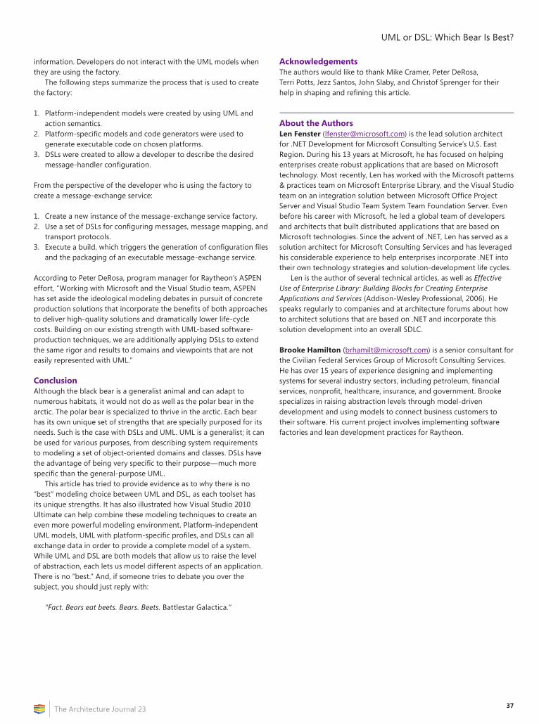
37
UML or DSL: Which Bear Is Best?
The Architecture Journal 23
information. Developers do not interact with the UML models when they are using the factory.
The following steps summarize the process that is used to create the factory:
1. Platform-independent models were created by using UML and action semantics.
2. Platform-specific models and code generators were used to generate executable code on chosen platforms.
3. DSLs were created to allow a developer to describe the desired message-handler configuration.
From the perspective of the developer who is using the factory to create a message-exchange service:
1. Create a new instance of the message-exchange service factory.2. Use a set of DSLs for configuring messages, message mapping, and
transport protocols.3. Execute a build, which triggers the generation of configuration files
and the packaging of an executable message-exchange service.
According to Peter DeRosa, program manager for Raytheon’s ASPEN effort, “Working with Microsoft and the Visual Studio team, ASPEN has set aside the ideological modeling debates in pursuit of concrete production solutions that incorporate the benefits of both approaches to deliver high-quality solutions and dramatically lower life-cycle costs. Building on our existing strength with UML-based software-production techniques, we are additionally applying DSLs to extend the same rigor and results to domains and viewpoints that are not easily represented with UML.”
ConclusionAlthough the black bear is a generalist animal and can adapt to numerous habitats, it would not do as well as the polar bear in the arctic. The polar bear is specialized to thrive in the arctic. Each bear has its own unique set of strengths that are specially purposed for its needs. Such is the case with DSLs and UML. UML is a generalist; it can be used for various purposes, from describing system requirements to modeling a set of object-oriented domains and classes. DSLs have the advantage of being very specific to their purpose—much more specific than the general-purpose UML.
This article has tried to provide evidence as to why there is no “best” modeling choice between UML and DSL, as each toolset has its unique strengths. It has also illustrated how Visual Studio 2010 Ultimate can help combine these modeling techniques to create an even more powerful modeling environment. Platform-independent UML models, UML with platform-specific profiles, and DSLs can all exchange data in order to provide a complete model of a system. While UML and DSL are both models that allow us to raise the level of abstraction, each lets us model different aspects of an application. There is no “best.” And, if someone tries to debate you over the subject, you should just reply with:
“Fact. Bears eat beets. Bears. Beets. Battlestar Galactica.”
AcknowledgementsThe authors would like to thank Mike Cramer, Peter DeRosa, Terri Potts, Jezz Santos, John Slaby, and Christof Sprenger for their help in shaping and refining this article.
About the AuthorsLen Fenster ([email protected]) is the lead solution architect for .NET Development for Microsoft Consulting Service’s U.S. East Region. During his 13 years at Microsoft, he has focused on helping enterprises create robust applications that are based on Microsoft technology. Most recently, Len has worked with the Microsoft patterns & practices team on Microsoft Enterprise Library, and the Visual Studio team on an integration solution between Microsoft Office Project Server and Visual Studio Team System Team Foundation Server. Even before his career with Microsoft, he led a global team of developers and architects that built distributed applications that are based on Microsoft technologies. Since the advent of .NET, Len has served as a solution architect for Microsoft Consulting Services and has leveraged his considerable experience to help enterprises incorporate .NET into their own technology strategies and solution-development life cycles.
Len is the author of several technical articles, as well as Effective Use of Enterprise Library: Building Blocks for Creating Enterprise Applications and Services (Addison-Wesley Professional, 2006). He speaks regularly to companies and at architecture forums about how to architect solutions that are based on .NET and incorporate this solution development into an overall SDLC.
Brooke Hamilton ([email protected]) is a senior consultant for the Civilian Federal Services Group of Microsoft Consulting Services. He has over 15 years of experience designing and implementing systems for several industry sectors, including petroleum, financial services, nonprofit, healthcare, insurance, and government. Brooke specializes in raising abstraction levels through model-driven development and using models to connect business customers to their software. His current project involves implementing software factories and lean development practices for Raytheon.
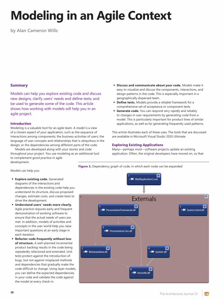
38 The Architecture Journal 23
Summary
Models can help you explore existing code and discuss new designs; clarify users’ needs and define tests; and be used to generate some of the code. This article shows how working with models will help you in an agile project.
IntroductionModeling is a valuable tool for an agile team. A model is a view of a chosen aspect of your application, such as the sequence of interactions among components; the business activities of users; the language of user concepts and relationships that is ubiquitous in the design; or the dependencies among different parts of the code.
Models are developed along with your stories and code throughout your project. You use modeling as an additional tool to complement good practice in agile development.
Models can help you:
• Explore existing code. Generated diagrams of the interactions and dependencies in the existing code help you understand its structure, discuss proposed changes, estimate costs, and create tests to drive the development.
• Understand users’ needs more clearly. Agile practice requires early and frequent demonstration of working software to ensure that the actual needs of users are met. In addition, models of activities and concepts in the user world help you raise important questions at an early stage in each iteration.
• Refactor code frequently without loss of structure. A well-planned incremental product backlog results in the code being repeatedly refactored and extended. Unit tests protect against the introduction of bugs, but not against misplaced methods and dependencies that gradually make the code difficult to change. Using layer models, you can define the expected dependencies in your code and validate the code against the model at every check-in.
• Discuss and communicate about your code. Models make it easy to visualize and discuss the components, interactions, and design patterns in the code. This is especially important in a geographically dispersed team.
• Define tests. Models provide a reliable framework for a comprehensive set of acceptance or component tests.
• Generate code. You can respond very rapidly and reliably to changes in user requirements by generating code from a model. This is particularly important for product lines of similar applications, as well as for generating frequently used patterns.
This article illustrates each of these uses. The tools that are discussed are available in Microsoft Visual Studio 2010 Ultimate.
Exploring Existing ApplicationsMany—perhaps most—software projects update an existing application. Often, the original developers have moved on, so that
Modeling in an Agile Contextby Alan Cameron Wills
Figure 1: Dependency graph of code, in which each node can be expanded
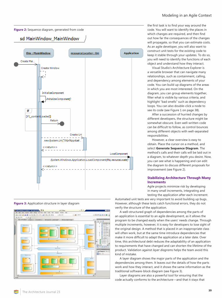
39
Modeling in an Agile Context
The Architecture Journal 23
the first task is to find your way around the code. You will want to identify the places in which changes are required, and then find out how far the consequences of the changes will propagate, so that you can estimate costs. As an agile developer, you will also want to construct unit tests for the existing code to keep it stable through your updates. To do so, you will need to identify the functions of each object and understand how they interact.
Visual Studio’s Architecture Explorer is a versatile browser that can navigate many relationships, such as containment, calling, and dependency among elements of your code. You can build up diagrams of the areas in which you are most interested. On the diagram, you can group elements together, filter what is visible by various criteria, and highlight “bad smells” such as dependency loops. You can also double-click a node to see its code (see Figure 1 on page 38).
After a succession of hurried changes by different developers, the structure might be somewhat obscure. Even well-written code can be difficult to follow, as control bounces among different objects with well-separated responsibilities.
However, a clear overview is easy to obtain. Place the cursor on a method, and select Generate Sequence Diagram. The method’s calls and their calls will be laid out in a diagram, to whatever depth you desire. Now, you can see what is happening and can edit the diagram to discuss different proposals for improvement (see Figure 2).
Stabilizing Architecture Through Many IncrementsAgile projects minimize risk by developing in many small increments, integrating and testing the application after each increment.
Automated unit tests are very important to avoid building up bugs. However, although these tests catch functional errors, they do not verify the structure of the application.
A well-structured graph of dependencies among the parts of an application is essential to an agile development, as it allows the program to be changed easily when the users’ needs change. Through multiple increments, however, it is easy for developers to lose sight of the original design. A method that is placed in an inappropriate class will often work, but at the same time introduce dependencies that make it more difficult to adapt the application at a later date. Over time, this architectural debt reduces the adaptability of an application to requirements that have changed and can shorten the lifetime of the product. Validation against layer diagrams helps the team avoid this kind of mistake.
A layer diagram shows the major parts of the application and the dependencies among them. It leaves out the details of how the parts work and how they interact, and it shows the same information as the traditional software-block diagram (see Figure 3).
Layer diagrams are also a powerful tool for ensuring that the code actually conforms to the architecture—and that it stays that
Figure 2: Sequence diagram, generated from code
Figure 3: Application structure in layer diagram
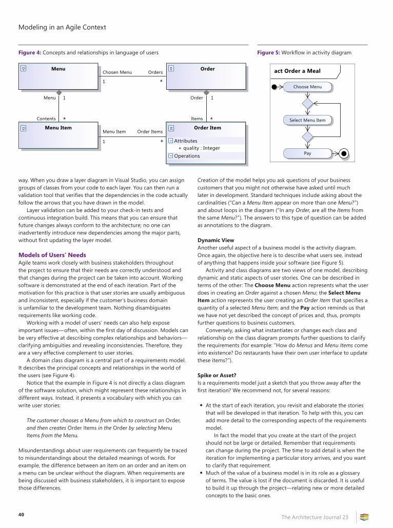
Modeling in an Agile Context
The Architecture Journal 2340
way. When you draw a layer diagram in Visual Studio, you can assign groups of classes from your code to each layer. You can then run a validation tool that verifies that the dependencies in the code actually follow the arrows that you have drawn in the model.
Layer validation can be added to your check-in tests and continuous integration build. This means that you can ensure that future changes always conform to the architecture; no one can inadvertently introduce new dependencies among the major parts, without first updating the layer model.
Models of Users’ NeedsAgile teams work closely with business stakeholders throughout the project to ensure that their needs are correctly understood and that changes during the project can be taken into account. Working software is demonstrated at the end of each iteration. Part of the motivation for this practice is that user stories are usually ambiguous and inconsistent, especially if the customer’s business domain is unfamiliar to the development team. Nothing disambiguates requirements like working code.
Working with a model of users’ needs can also help expose important issues—often, within the first day of discussion. Models can be very effective at describing complex relationships and behaviors—clarifying ambiguities and revealing inconsistencies. Therefore, they are a very effective complement to user stories.
A domain class diagram is a central part of a requirements model. It describes the principal concepts and relationships in the world of the users (see Figure 4).
Notice that the example in Figure 4 is not directly a class diagram of the software solution, which might represent these relationships in different ways. Instead, it presents a vocabulary with which you can write user stories:
The customer chooses a Menu from which to construct an Order, and then creates Order Items in the Order by selecting Menu Items from the Menu.
Misunderstandings about user requirements can frequently be traced to misunderstandings about the detailed meanings of words. For example, the difference between an item on an order and an item on a menu can be unclear without the diagram. When requirements are being discussed with business stakeholders, it is important to expose those differences.
Creation of the model helps you ask questions of your business customers that you might not otherwise have asked until much later in development. Standard techniques include asking about the cardinalities (“Can a Menu Item appear on more than one Menu?”) and about loops in the diagram (“In any Order, are all the Items from the same Menu?”). The answers to this type of question can be added as annotations to the diagram.
Dynamic ViewAnother useful aspect of a business model is the activity diagram. Once again, the objective here is to describe what users see, instead of anything that happens inside your software (see Figure 5).
Activity and class diagrams are two views of one model, describing dynamic and static aspects of user stories. One can be described in terms of the other: The Choose Menu action represents what the user does in creating an Order against a chosen Menu; the Select Menu Item action represents the user creating an Order Item that specifies a quantity of a selected Menu Item; and the Pay action reminds us that we have not yet described the concept of prices and, thus, prompts further questions to business customers.
Conversely, asking what instantiates or changes each class and relationship on the class diagram prompts further questions to clarify the requirements (for example: “How do Menus and Menu Items come into existence? Do restaurants have their own user interface to update these items?”).
Spike or Asset?Is a requirements model just a sketch that you throw away after the first iteration? We recommend not, for several reasons:
• At the start of each iteration, you revisit and elaborate the stories that will be developed in that iteration. To help with this, you can add more detail to the corresponding aspects of the requirements model.
In fact the model that you create at the start of the project should not be large or detailed. Remember that requirements can change during the project. The time to add detail is when the iteration for implementing a particular story arrives, and you want to clarify that requirement.
• Much of the value of a business model is in its role as a glossary of terms. The value is lost if the document is discarded. It is useful to build it up through the project—relating new or more detailed concepts to the basic ones.
Figure 4: Concepts and relationships in language of users
Menu Order
Menu Item Order Item
Menu
Contents
Chosen Menu Orders
Order Items
1
1 *
1 *
Order 1
* *Items
Menu Item
Attributes+ quality : Integer
Operations
Figure 5: Workflow in activity diagram
act Order a Meal
Choose Menu
Pay
Select Menu Item
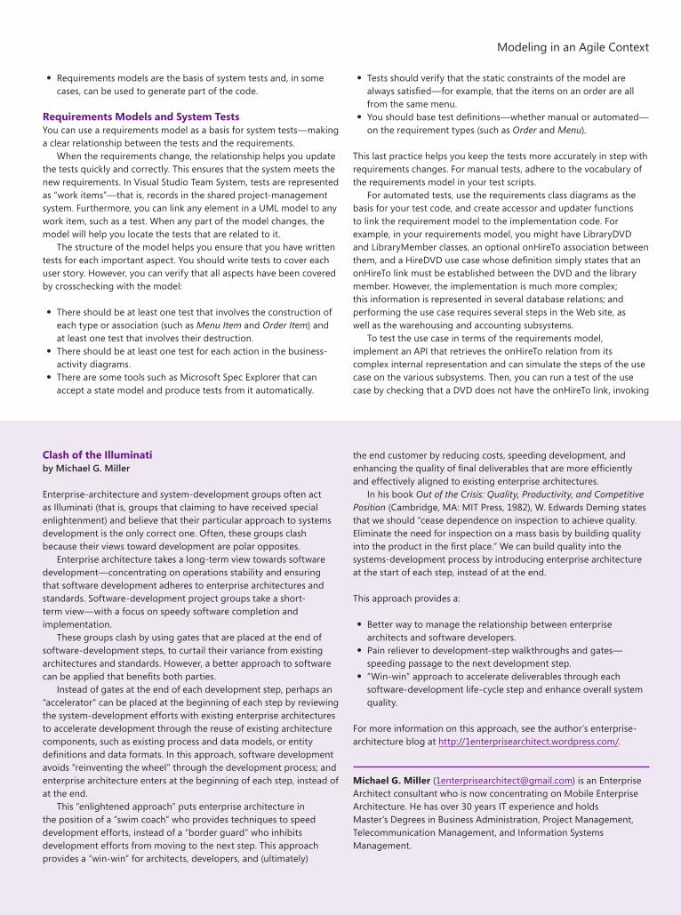
41
Modeling in an Agile Context
The Architecture Journal 23
• Requirements models are the basis of system tests and, in some cases, can be used to generate part of the code.
Requirements Models and System TestsYou can use a requirements model as a basis for system tests—making a clear relationship between the tests and the requirements.
When the requirements change, the relationship helps you update the tests quickly and correctly. This ensures that the system meets the new requirements. In Visual Studio Team System, tests are represented as “work items”—that is, records in the shared project-management system. Furthermore, you can link any element in a UML model to any work item, such as a test. When any part of the model changes, the model will help you locate the tests that are related to it.
The structure of the model helps you ensure that you have written tests for each important aspect. You should write tests to cover each user story. However, you can verify that all aspects have been covered by crosschecking with the model:
• There should be at least one test that involves the construction of each type or association (such as Menu Item and Order Item) and at least one test that involves their destruction.
• There should be at least one test for each action in the business-activity diagrams.
• There are some tools such as Microsoft Spec Explorer that can accept a state model and produce tests from it automatically.
• Tests should verify that the static constraints of the model are always satisfied—for example, that the items on an order are all from the same menu.
• You should base test definitions—whether manual or automated—on the requirement types (such as Order and Menu).
This last practice helps you keep the tests more accurately in step with requirements changes. For manual tests, adhere to the vocabulary of the requirements model in your test scripts.
For automated tests, use the requirements class diagrams as the basis for your test code, and create accessor and updater functions to link the requirement model to the implementation code. For example, in your requirements model, you might have LibraryDVD and LibraryMember classes, an optional onHireTo association between them, and a HireDVD use case whose definition simply states that an onHireTo link must be established between the DVD and the library member. However, the implementation is much more complex; this information is represented in several database relations; and performing the use case requires several steps in the Web site, as well as the warehousing and accounting subsystems.
To test the use case in terms of the requirements model, implement an API that retrieves the onHireTo relation from its complex internal representation and can simulate the steps of the use case on the various subsystems. Then, you can run a test of the use case by checking that a DVD does not have the onHireTo link, invoking
Clash of the Illuminatiby Michael G. Miller
Enterprise-architecture and system-development groups often act as Illuminati (that is, groups that claiming to have received special enlightenment) and believe that their particular approach to systems development is the only correct one. Often, these groups clash because their views toward development are polar opposites.
Enterprise architecture takes a long-term view towards software development—concentrating on operations stability and ensuring that software development adheres to enterprise architectures and standards. Software-development project groups take a short-term view—with a focus on speedy software completion and implementation.
These groups clash by using gates that are placed at the end of software-development steps, to curtail their variance from existing architectures and standards. However, a better approach to software can be applied that benefits both parties.
Instead of gates at the end of each development step, perhaps an “accelerator” can be placed at the beginning of each step by reviewing the system-development efforts with existing enterprise architectures to accelerate development through the reuse of existing architecture components, such as existing process and data models, or entity definitions and data formats. In this approach, software development avoids “reinventing the wheel” through the development process; and enterprise architecture enters at the beginning of each step, instead of at the end.
This “enlightened approach” puts enterprise architecture in the position of a “swim coach” who provides techniques to speed development efforts, instead of a “border guard” who inhibits development efforts from moving to the next step. This approach provides a “win-win” for architects, developers, and (ultimately)
the end customer by reducing costs, speeding development, and enhancing the quality of final deliverables that are more efficiently and effectively aligned to existing enterprise architectures.
In his book Out of the Crisis: Quality, Productivity, and Competitive Position (Cambridge, MA: MIT Press, 1982), W. Edwards Deming states that we should “cease dependence on inspection to achieve quality. Eliminate the need for inspection on a mass basis by building quality into the product in the first place.” We can build quality into the systems-development process by introducing enterprise architecture at the start of each step, instead of at the end.
This approach provides a:
• Better way to manage the relationship between enterprise architects and software developers.
• Pain reliever to development-step walkthroughs and gates—speeding passage to the next development step.
• “Win-win” approach to accelerate deliverables through each software-development life-cycle step and enhance overall system quality.
For more information on this approach, see the author’s enterprise-architecture blog at http://1enterprisearchitect.wordpress.com/.
Michael G. Miller ([email protected]) is an Enterprise Architect consultant who is now concentrating on Mobile Enterprise Architecture. He has over 30 years IT experience and holds Master’s Degrees in Business Administration, Project Management, Telecommunication Management, and Information Systems Management.
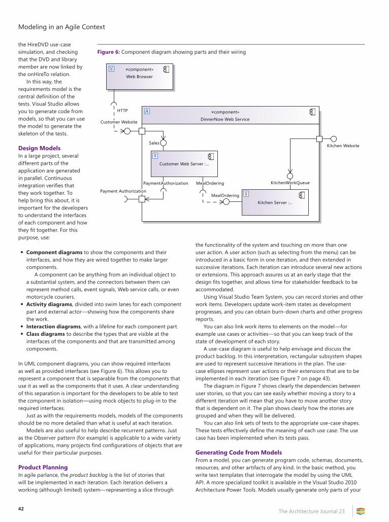
Modeling in an Agile Context
The Architecture Journal 2342
the HireDVD use-case simulation, and checking that the DVD and library member are now linked by the onHireTo relation.
In this way, the requirements model is the central definition of the tests. Visual Studio allows you to generate code from models, so that you can use the model to generate the skeleton of the tests.
Design ModelsIn a large project, several different parts of the application are generated in parallel. Continuous integration verifies that they work together. To help bring this about, it is important for the developers to understand the interfaces of each component and how they fit together. For this purpose, use:
• Component diagrams to show the components and their interfaces, and how they are wired together to make larger components.
A component can be anything from an individual object to a substantial system, and the connectors between them can represent method calls, event signals, Web service calls, or even motorcycle couriers.
• Activity diagrams, divided into swim lanes for each component part and external actor—showing how the components share the work.
• Interaction diagrams, with a lifeline for each component part.• Class diagrams to describe the types that are visible at the
interfaces of the components and that are transmitted among components.
In UML component diagrams, you can show required interfaces as well as provided interfaces (see Figure 6). This allows you to represent a component that is separable from the components that use it as well as the components that it uses. A clear understanding of this separation is important for the developers to be able to test the component in isolation—using mock objects to plug-in to the required interfaces.
Just as with the requirements models, models of the components should be no more detailed than what is useful at each iteration.
Models are also useful to help describe recurrent patterns. Just as the Observer pattern (for example) is applicable to a wide variety of applications, many projects find configurations of objects that are useful for their particular purposes.
Product PlanningIn agile parlance, the product backlog is the list of stories that will be implemented in each iteration. Each iteration delivers a working (although limited) system—representing a slice through
the functionality of the system and touching on more than one user action. A user action (such as selecting from the menu) can be introduced in a basic form in one iteration, and then extended in successive iterations. Each iteration can introduce several new actions or extensions. This approach assures us at an early stage that the design fits together, and allows time for stakeholder feedback to be accommodated.
Using Visual Studio Team System, you can record stories and other work items. Developers update work-item states as development progresses, and you can obtain burn-down charts and other progress reports.
You can also link work items to elements on the model—for example use cases or activities—so that you can keep track of the state of development of each story.
A use-case diagram is useful to help envisage and discuss the product backlog. In this interpretation, rectangular subsystem shapes are used to represent successive iterations in the plan. The use-case ellipses represent user actions or their extensions that are to be implemented in each iteration (see Figure 7 on page 43).
The diagram in Figure 7 shows clearly the dependencies between user stories, so that you can see easily whether moving a story to a different iteration will mean that you have to move another story that is dependent on it. The plan shows clearly how the stories are grouped and when they will be delivered.
You can also link sets of tests to the appropriate use-case shapes. These tests effectively define the meaning of each use case: The use case has been implemented when its tests pass.
Generating Code from ModelsFrom a model, you can generate program code, schemas, documents, resources, and other artifacts of any kind. In the basic method, you write text templates that interrogate the model by using the UML API. A more specialized toolkit is available in the Visual Studio 2010 Architecture Power Tools. Models usually generate only parts of your
Figure 6: Component diagram showing parts and their wiring
Web Browser
«component»
Customer Website
PaymentAuthorization MealOrdering KitchenWorkQueue
MealOrdering
Kitchen Website
Payment Authorization
HTTP
Sales
DinnerNow Web Service
«component»
Customer Web Server :...
Kitchen Server :...
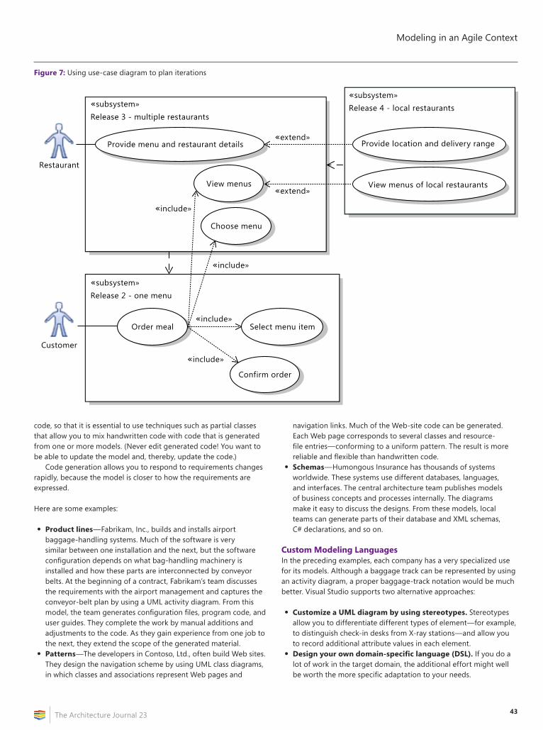
43
Modeling in an Agile Context
The Architecture Journal 23
code, so that it is essential to use techniques such as partial classes that allow you to mix handwritten code with code that is generated from one or more models. (Never edit generated code! You want to be able to update the model and, thereby, update the code.)
Code generation allows you to respond to requirements changes rapidly, because the model is closer to how the requirements are expressed.
Here are some examples:
• Product lines—Fabrikam, Inc., builds and installs airport baggage-handling systems. Much of the software is very similar between one installation and the next, but the software configuration depends on what bag-handling machinery is installed and how these parts are interconnected by conveyor belts. At the beginning of a contract, Fabrikam’s team discusses the requirements with the airport management and captures the conveyor-belt plan by using a UML activity diagram. From this model, the team generates configuration files, program code, and user guides. They complete the work by manual additions and adjustments to the code. As they gain experience from one job to the next, they extend the scope of the generated material.
• Patterns—The developers in Contoso, Ltd., often build Web sites. They design the navigation scheme by using UML class diagrams, in which classes and associations represent Web pages and
navigation links. Much of the Web-site code can be generated. Each Web page corresponds to several classes and resource-file entries—conforming to a uniform pattern. The result is more reliable and flexible than handwritten code.
• Schemas—Humongous Insurance has thousands of systems worldwide. These systems use different databases, languages, and interfaces. The central architecture team publishes models of business concepts and processes internally. The diagrams make it easy to discuss the designs. From these models, local teams can generate parts of their database and XML schemas, C# declarations, and so on.
Custom Modeling LanguagesIn the preceding examples, each company has a very specialized use for its models. Although a baggage track can be represented by using an activity diagram, a proper baggage-track notation would be much better. Visual Studio supports two alternative approaches:
• Customize a UML diagram by using stereotypes. Stereotypes allow you to differentiate different types of element—for example, to distinguish check-in desks from X-ray stations—and allow you to record additional attribute values in each element.
• Design your own domain-specific language (DSL). If you do a lot of work in the target domain, the additional effort might well be worth the more specific adaptation to your needs.
Figure 7: Using use-case diagram to plan iterations
View menus
«extend»
«extend»
«include»
«include»
«include»
«include»
Provide menu and restaurant details
Release 3 - multiple restaurants
Customer
Restaurant
Provide location and delivery range
View menus of local restaurants
Release 4 - local restaurants
Choose menu
Order meal
Confirm order
Select menu item
«subsystem»
Release 2 - one menu«subsystem»
«subsystem»
Modeling in an Agile Context
The Architecture Journal 2344
The Visual Studio SDK also allows you to design menu commands, validation tests, and toolbox items for both of these types of model. You can also build Visual Studio extensions that integrate diagrams together and couple them to external resources such as databases.
ConclusionModels work well in an agile context. They are not about big upfront design, but are developed along with your stories and code. Models can help you explore and refactor an existing system, clarify users’ needs at an early stage, and discuss and communicate many aspects of your code. They can act as a solid framework for tests to help ensure that everything is covered. You can specialize the Visual Studio modeling tools to your own needs, including the ability to generate code from them—which can make your response to requirements changes very agile, indeed.
AcknowledgmentsThanks to David Trowbridge, Jamie Cool, Steve Cook, Peter Provost, Stuart Kent, and Cameron Skinner.
Further ReadingVisual Studio Team System. “Modeling the Application.” Microsoft Developer Network (MSDN).
Visual Studio Team System. “MSF for Agile Software Development v5.0.” MSDN.
Evans, Eric. Domain Driven Design: Tackling Complexity in the Heart of Software. Boston, MA: Addison-Wesley, 2004.
Ambler, Scott W. “Agile Modeling.” Agile Modeling (AM) Home Page.
About the AuthorAlan Cameron Wills ([email protected]) is a programming writer in Microsoft, who works on modeling and process-support tools. He has been a developer on the Domain-Specific Language and process-guidance teams. Before joining Microsoft, Alan was a consultant in UML and agile development.
Combining Client and Provider Methodologies in Custom Software Developmentby Henry Rosales-Parra
The situation: You are part of a custom software-development company that is using a certain methodology to deliver your projects. On the other hand, your client has its own in-house software-development methodology that is tightly coupled with a project-management discipline, and without a chance of being overlooked. How can you cope with this situation?
Here are some useful tips:
• Try to negotiate adjustments to make certain methodology components flexible on both ends. Sit down with your client, and conduct a review of the procedures. Sometimes, you can gain additional know-how from your client and introduce new elements or changes into your methodology. Be sure that the resultant set of parts of the methodology is known and approved by both parties.
• Follow a simple right-hand rule. Allow changes in your methodology if they make the requirements clearer, ease technical decisions, decrease development times, or increase the quality of the software. Take into account how changes in methodology affect your budget.
• Involve the client in architectural decisions, but only if necessary. First, be sure that you have all functional requirements and technical information; then, make the appropriate decisions. If the client is required to be part of the architectural decisions, anyway, do not forget that your mission is to provide solutions; therefore, come up with well-studied options.
• Do not fall into the excessive-documentation trap. Avoid allowing your project to become a “documentation project.” Allow documents to be a foundation, instead of an objective.
• Do not allow any quality process to be removed. These are not optional. Allow the client to take part in testing procedures, but preferably with the purpose of checking that all requirements are covered. Usually, allowing the client to be involved in “bug hunting” is counterproductive if the process is not well-understood as part of a stabilization phase.
• Do you use an agile methodology, but your client counts on a more formal approach? Let the formal envisioning and design-phase deliverables be the input of your agile-development sessions. In the development phase, introduce the concept of “requirements micro-segmentation”: Convert groups of formal requirements into mini agile projects—for example, creating a chain of fully built components/modules and conducting additional testing sessions at the end of one or more blocks of requirements. Performance of one or more deployment sessions would depend on the completeness of each developed block.
For more information, please visit my blog.
Henry Rosales-Parra ([email protected]) is the Technology Manager for Integra Tecnología, a Colombia-based software-development company.

subscribe at
www.architecturejournal.net23