Carlos Fernández Casado y José Acuña: los primeros puentes ...
ARCHITECTURAL SUPPORT FOR SECURITY MANAGEMENT
IN ENTERPRISE NETWORKS
A DISSERTATION
SUBMITTED TO THE DEPARTMENT OF COMPUTER SCIENCE
AND THE COMMITTEE ON GRADUATE STUDIES
OF STANFORD UNIVERSITY
IN PARTIAL FULFILLMENT OF THE REQUIREMENTS
FOR THE DEGREE OF
DOCTOR OF PHILOSOPHY
Martın Casado
December 2007

c© Copyright by Martın Casado 2008
All Rights Reserved
ii

I certify that I have read this dissertation and that, in my opinion, it
is fully adequate in scope and quality as a dissertation for the degree
of Doctor of Philosophy.
(Nick McKeown) Principal Adviser
I certify that I have read this dissertation and that, in my opinion, it
is fully adequate in scope and quality as a dissertation for the degree
of Doctor of Philosophy.
(Scott Shenker)
I certify that I have read this dissertation and that, in my opinion, it
is fully adequate in scope and quality as a dissertation for the degree
of Doctor of Philosophy.
(Dan Boneh)
Approved for the University Committee on Graduate Studies.
iii

To my parents,
and their power to lend dreams.
And to my niece Brittani,
and her power to achieve them.
iv
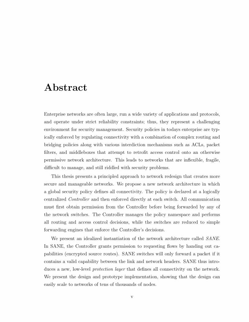
Abstract
Enterprise networks are often large, run a wide variety of applications and protocols,
and operate under strict reliability constraints; thus, they represent a challenging
environment for security management. Security policies in todays enterprise are typ-
ically enforced by regulating connectivity with a combination of complex routing and
bridging policies along with various interdiction mechanisms such as ACLs, packet
filters, and middleboxes that attempt to retrofit access control onto an otherwise
permissive network architecture. This leads to networks that are inflexible, fragile,
difficult to manage, and still riddled with security problems.
This thesis presents a principled approach to network redesign that creates more
secure and manageable networks. We propose a new network architecture in which
a global security policy defines all connectivity. The policy is declared at a logically
centralized Controller and then enforced directly at each switch. All communication
must first obtain permission from the Controller before being forwarded by any of
the network switches. The Controller manages the policy namespace and performs
all routing and access control decisions, while the switches are reduced to simple
forwarding engines that enforce the Controller’s decisions.
We present an idealized instantiation of the network architecture called SANE.
In SANE, the Controller grants permission to requesting flows by handing out ca-
pabilities (encrypted source routes). SANE switches will only forward a packet if it
contains a valid capability between the link and network headers. SANE thus intro-
duces a new, low-level protection layer that defines all connectivity on the network.
We present the design and prototype implementation, showing that the design can
easily scale to networks of tens of thousands of nodes.
v
SANE would require a fork-lift replacement of an enterprise’s entire networking
infrastructure and changes to all the end-hosts. While this might be suitable in some
cases, it is clearly a significant impediment to widespread adoption. To address this,
we present Ethane a deployable instantiation of our architecture. Ethane does not
require modification to end-hosts and can be incrementally deployed within an exist-
ing network. Instead of handing out capabilities, permission is granted by explicitly
setting up flows at each switch. We have implemented Ethane in both hardware
and software, supporting both wired and wireless hosts. We describe our experience
managing an operational Ethane network of over 300 hosts.
vi

Acknowledgements
It is hard to overstate the impact my adviser, Nick McKeown, has had on my growth
as a student, an engineer, and a researcher. His introductory networking course,
which I took prior to attending graduate school, re-enforced my passion for networks,
led me to apply for the Ph.D. program, and remains the best class I have ever taken.
Through example, Nick has shaped my perception of what it takes to be a world class
researcher: unwavering focus, comfort with risk, trend skepticism, attention to detail,
and the ability to discern deep results over shallow findings. He is a model researcher,
an accomplished entrepreneur, an inspiring educator, and a brilliant adviser. I am
deeply honored to be a member of his group.
I would also like to thank Dan Boneh and Scott Shenker for their mentorship dur-
ing my studies. In addition to research guidance, I am very grateful for the comments
and feedback they provided while enduring positions on my reading committee.
The primary focus of my thesis grew out of the SANE and Ethane projects,
neither of which would have been successful without our exceptionally skilled team.
I would like to thank Michael Freedman, Tal Garfinkel, Justin Pettit, Jianying Luo,
Aditya Akella, Natasha Gude, Gregory Watson, Dan Boneh, Scott Shenker and Nick
McKeown for their many significant contributions.
Throughout my graduate studies I was fortunate enough to be a member of the
high performance networking group, the best research group on the planet. Every
member has had a hand in very positively shaping my graduate experience. In ad-
dition to those already mentioned, I thank Guido Appenzeller, Shang-Tse Chuang,
Isaac Keslassy, Sundar Iyer, Neda Beheshti, Nandita Dukkipati, Glenn Gibb, Yashar
vii

Ganjali, Jad Naous, Rui Zhang-Shen, Dan Wendlandt, Paul Tarjan, and David Er-
ickson.
I also had the privilege to work with a number of extremely talented researchers
outside of my core research group. With each new project, I learned a little more
about software development, research, writing, and the vicissitudes of the peer review
process. Certainly, my acquired skill-set over the last few years was largely snatched,
borrowed, pilfered, and copied from my various collaborators. To this end, I would like
to thank Pei Cao, Aditya Akella, Tal Garfinkel, Vern Paxson, and Michael Freedman.
Finally, I would like to thank my wife Kristin – I simply could not have managed
without her encouragement and support. It is widely accepted that being the spouse of
a Ph.D. student requires tremendous patience and understanding. A less well-known
corollary is that these requirements are doubled if the field of study is computer
science, and again doubled if Nick is the research adviser. Enduring the trek with me
was a monumental feat for which I will always be grateful. Above all, thanks to you,
my love.
viii
Contents
iv
Abstract v
Acknowledgements vii
1 Introduction 1
1.1 Problems with Current Approaches . . . . . . . . . . . . . . . . . . . 2
1.2 Solution Requirements . . . . . . . . . . . . . . . . . . . . . . . . . . 4
1.2.1 Threat Environment . . . . . . . . . . . . . . . . . . . . . . . 6
1.3 A Centralized, Default-Off Solution . . . . . . . . . . . . . . . . . . . 6
1.4 Why Focus on the Enterprise? . . . . . . . . . . . . . . . . . . . . . . 8
1.5 Previous Works . . . . . . . . . . . . . . . . . . . . . . . . . . . . . . 9
1.6 Organization of Thesis . . . . . . . . . . . . . . . . . . . . . . . . . . 11
2 SANE: An Idealized Architecture 13
2.1 Introduction . . . . . . . . . . . . . . . . . . . . . . . . . . . . . . . . 13
2.2 System Architecture . . . . . . . . . . . . . . . . . . . . . . . . . . . 13
2.2.1 Controller . . . . . . . . . . . . . . . . . . . . . . . . . . . . . 14
2.2.2 Network Service Directory . . . . . . . . . . . . . . . . . . . . 16
2.2.3 Protection Layer . . . . . . . . . . . . . . . . . . . . . . . . . 17
2.2.4 Interoperability . . . . . . . . . . . . . . . . . . . . . . . . . . 21
2.2.5 Fault Tolerance . . . . . . . . . . . . . . . . . . . . . . . . . . 22
2.2.6 Additional Features . . . . . . . . . . . . . . . . . . . . . . . . 23
ix
2.3 Attack Resistance . . . . . . . . . . . . . . . . . . . . . . . . . . . . . 25
2.3.1 Resource Exhaustion . . . . . . . . . . . . . . . . . . . . . . . 26
2.3.2 Tolerating Malicious Switches . . . . . . . . . . . . . . . . . . 27
2.3.3 Tolerating a Malicious Controller . . . . . . . . . . . . . . . . 29
2.4 Implementation . . . . . . . . . . . . . . . . . . . . . . . . . . . . . . 29
2.4.1 IP Proxies and SANE Switches . . . . . . . . . . . . . . . . . 30
2.4.2 Controller . . . . . . . . . . . . . . . . . . . . . . . . . . . . . 30
2.4.3 Example Operation . . . . . . . . . . . . . . . . . . . . . . . . 31
2.5 Evaluation . . . . . . . . . . . . . . . . . . . . . . . . . . . . . . . . . 33
2.5.1 Microbenchmarks . . . . . . . . . . . . . . . . . . . . . . . . . 33
2.5.2 Scalability . . . . . . . . . . . . . . . . . . . . . . . . . . . . . 33
3 Ethane: A Deployable Architecture 36
3.1 Introduction . . . . . . . . . . . . . . . . . . . . . . . . . . . . . . . . 36
3.2 Overview of Ethane Design . . . . . . . . . . . . . . . . . . . . . . . . 38
3.2.1 Names, Bindings, and Policy Language . . . . . . . . . . . . . 39
3.2.2 Ethane in Use . . . . . . . . . . . . . . . . . . . . . . . . . . . 40
3.3 Ethane in More Detail . . . . . . . . . . . . . . . . . . . . . . . . . . 42
3.3.1 An Ethane Network . . . . . . . . . . . . . . . . . . . . . . . . 42
3.3.2 Switches . . . . . . . . . . . . . . . . . . . . . . . . . . . . . . 43
3.3.3 Controller . . . . . . . . . . . . . . . . . . . . . . . . . . . . . 46
3.3.4 Handling Broadcast and Multicast . . . . . . . . . . . . . . . 50
3.3.5 Replicating the Controller for Fault-Tolerance and Scalability 51
3.3.6 Link Failures . . . . . . . . . . . . . . . . . . . . . . . . . . . 53
3.3.7 Bootstrapping . . . . . . . . . . . . . . . . . . . . . . . . . . . 53
3.4 The Pol-Eth Policy Language . . . . . . . . . . . . . . . . . . . . . . 54
3.4.1 Overview . . . . . . . . . . . . . . . . . . . . . . . . . . . . . 54
3.4.2 Rule and Action Precedence . . . . . . . . . . . . . . . . . . . 55
3.4.3 Supporting Arbitrary Expressions . . . . . . . . . . . . . . . . 55
3.4.4 Policy Example . . . . . . . . . . . . . . . . . . . . . . . . . . 56
3.4.5 Implementation . . . . . . . . . . . . . . . . . . . . . . . . . . 56
x
3.5 Prototype and Deployment . . . . . . . . . . . . . . . . . . . . . . . . 58
3.5.1 Switches . . . . . . . . . . . . . . . . . . . . . . . . . . . . . . 58
3.5.2 Controller . . . . . . . . . . . . . . . . . . . . . . . . . . . . . 60
3.5.3 Deployment . . . . . . . . . . . . . . . . . . . . . . . . . . . . 61
3.6 Performance and Scalability . . . . . . . . . . . . . . . . . . . . . . . 62
3.6.1 Performance During Failures . . . . . . . . . . . . . . . . . . . 66
3.7 Ethane’s Shortcomings . . . . . . . . . . . . . . . . . . . . . . . . . . 67
4 Conclusions 70
A Pol-Eth Description 74
B Example Pol-Eth Policy File 78
C Switch Architecture 82
C.1 Switch Datapath . . . . . . . . . . . . . . . . . . . . . . . . . . . . . 83
C.2 Hardware Forwarding Path . . . . . . . . . . . . . . . . . . . . . . . . 84
C.2.1 Modules in the Datapath . . . . . . . . . . . . . . . . . . . . . 85
C.3 Switch Control Path . . . . . . . . . . . . . . . . . . . . . . . . . . . 87
Bibliography 89
xi
List of Tables
2.1 Performance of a Controller and switches . . . . . . . . . . . . . . . . 33
3.1 Hardware forwarding speeds for different packet sizes. All tests were run with full-
duplex traffic. Totals include Ethernet CRC, but not the Inter-Frame Gap or the
packet preamble. Tested with Ixia 1600T traffic generator. . . . . . . . . . . . 60
3.2 Completion time for HTTP GETs of 275 files during which the primary Controller
fails. Results are averaged over 5 runs. . . . . . . . . . . . . . . . . . . . . 66
xii
List of Figures
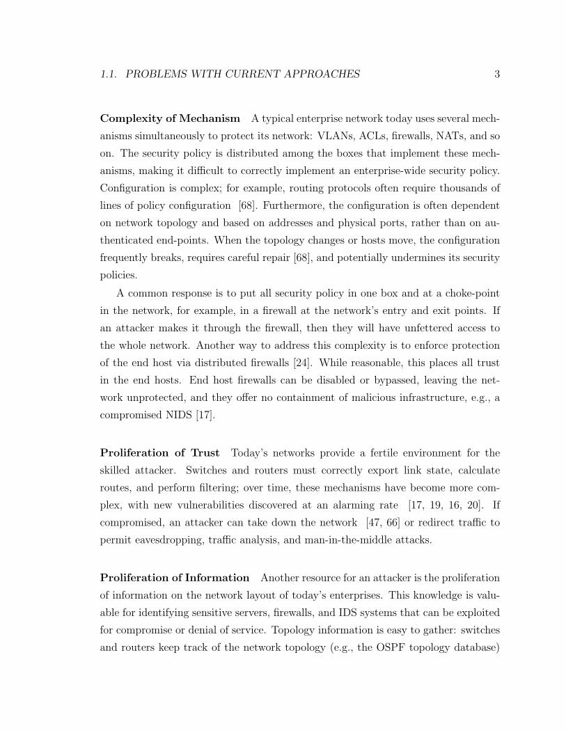
1.1 A traditional, distributed architecture (left) when compared to a cen-
tralized approach. With a centralized architecture, switches are re-
duced to simple forwarding elements while high level functions such
as routing, name bindings and address allocations are managed by a
single, centralized Controller. . . . . . . . . . . . . . . . . . . . . . . 7
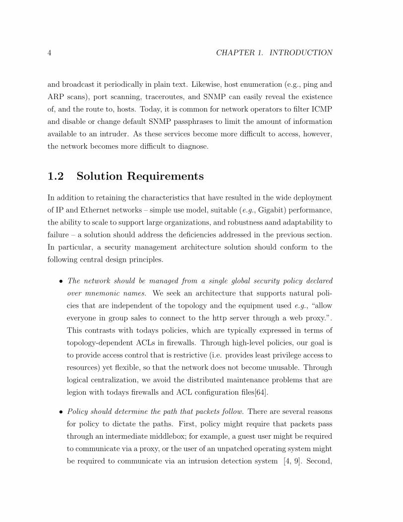
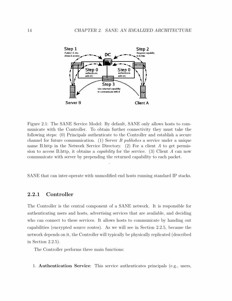
2.1 The SANE Service Model: By default, SANE only allows hosts to com-
municate with the Controller. To obtain further connectivity they must
take the following steps: (0) Principals authenticate to the Controller
and establish a secure channel for future communication. (1) Server B
publishes a service under a unique name B.http in the Network Service
Directory. (2) For a client A to get permission to access B.http, it
obtains a capability for the service. (3) Client A can now communicate
with server by prepending the returned capability to each packet. . . 14
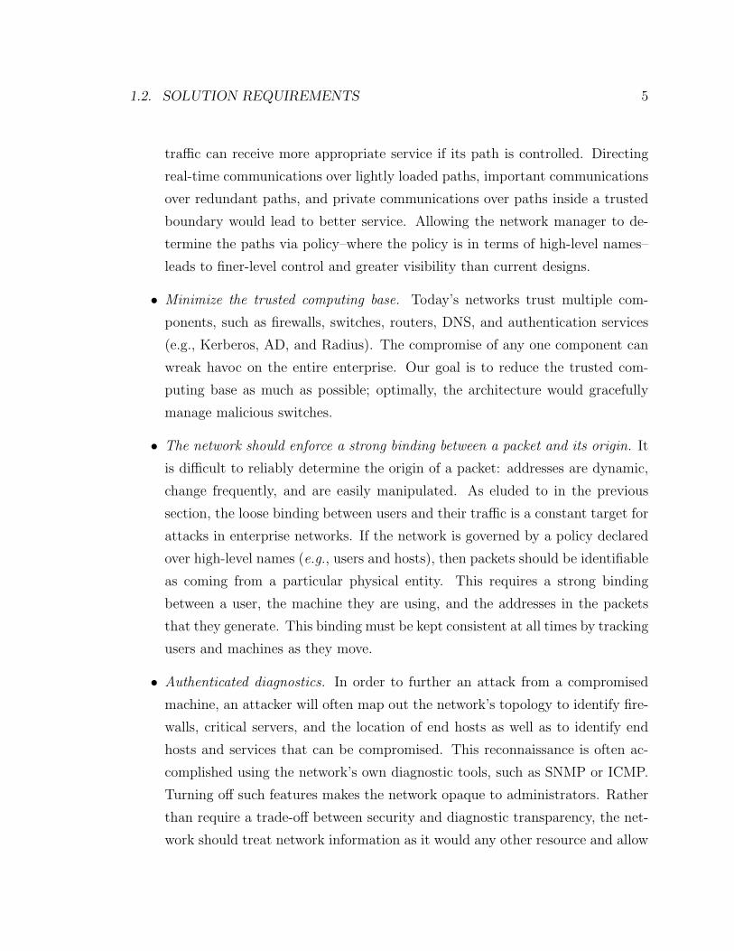
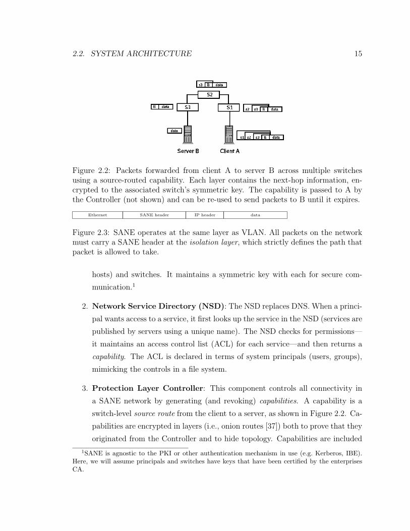
2.2 Packets forwarded from client A to server B across multiple switches
using a source-routed capability. Each layer contains the next-hop
information, encrypted to the associated switch’s symmetric key. The
capability is passed to A by the Controller (not shown) and can be
re-used to send packets to B until it expires. . . . . . . . . . . . . . . 15
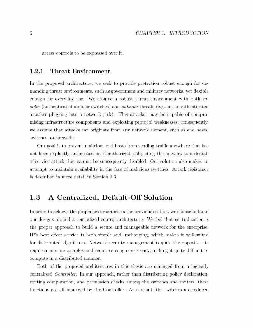
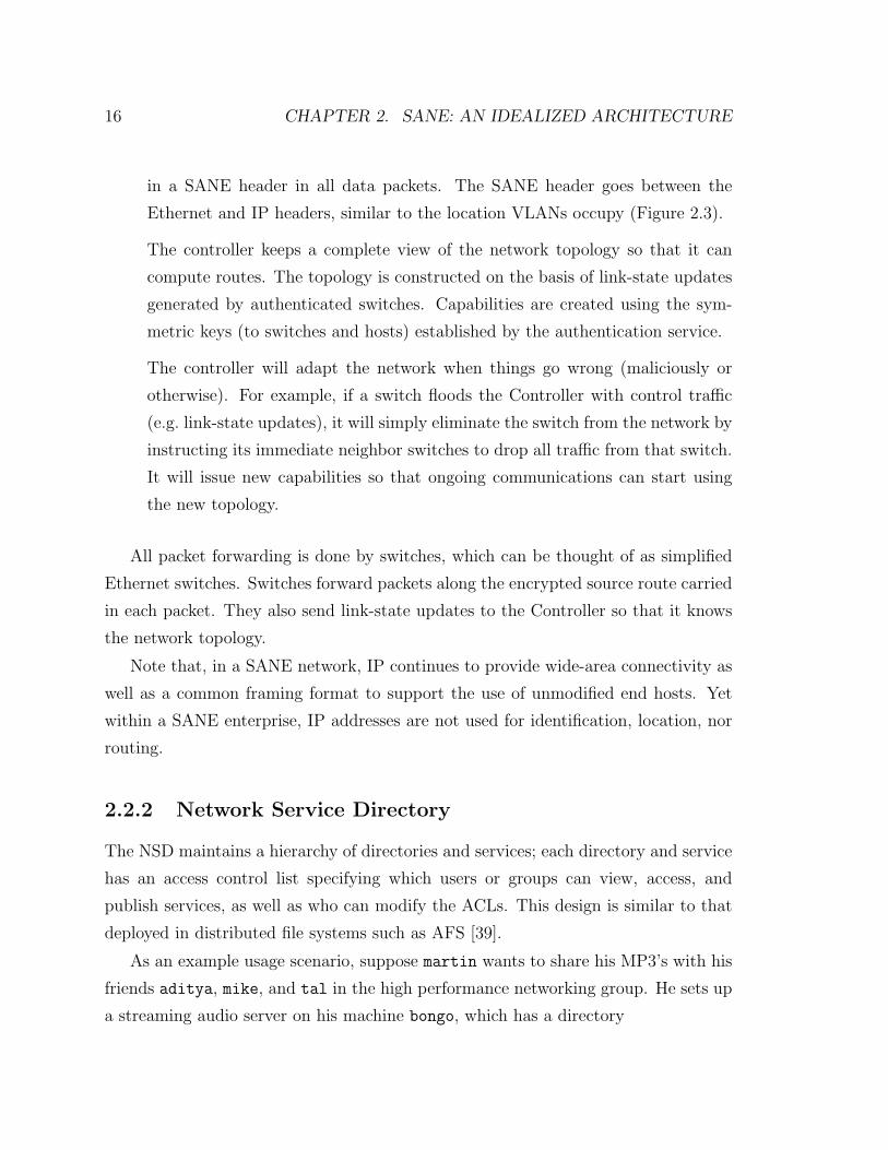
2.3 SANE operates at the same layer as VLAN. All packets on the network
must carry a SANE header at the isolation layer, which strictly defines
the path that packet is allowed to take. . . . . . . . . . . . . . . . . . 15
xiii
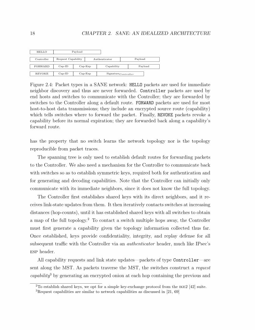
2.4 Packet types in a SANE network: HELLO packets are used for immediate
neighbor discovery and thus are never forwarded. Controller pack-
ets are used by end hosts and switches to communicate with the Con-
troller; they are forwarded by switches to the Controller along a default
route. FORWARD packets are used for most host-to-host data transmis-
sions; they include an encrypted source route (capability) which tells
switches where to forward the packet. Finally, REVOKE packets revoke a
capability before its normal expiration; they are forwarded back along
a capability’s forward route. . . . . . . . . . . . . . . . . . . . . . . . 18
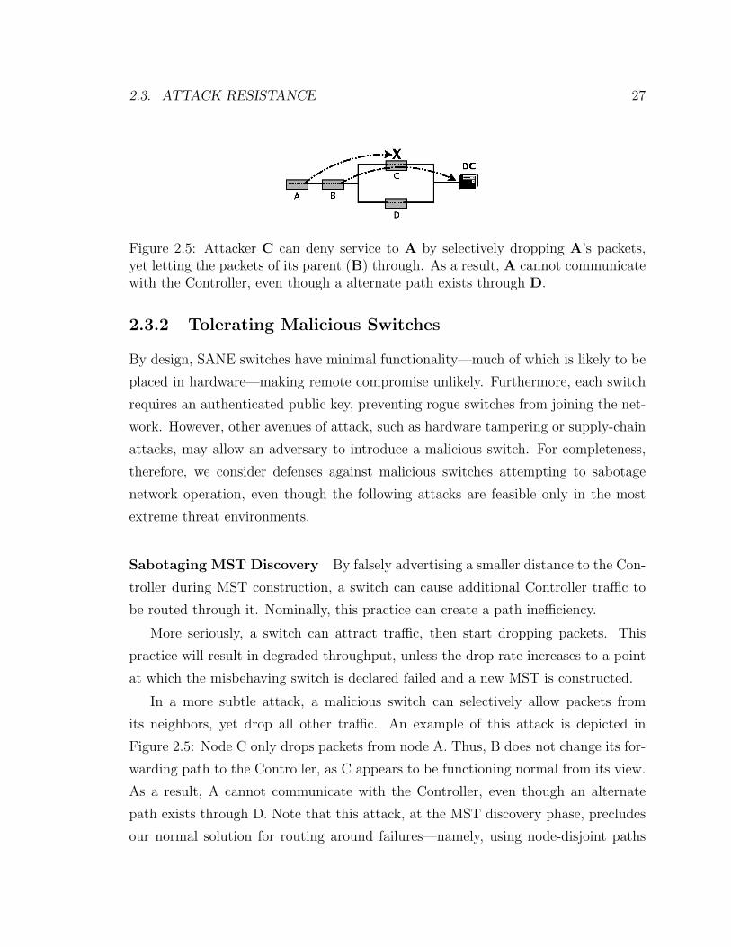
2.5 Attacker C can deny service to A by selectively dropping A’s packets,
yet letting the packets of its parent (B) through. As a result, A cannot
communicate with the Controller, even though a alternate path exists
through D. . . . . . . . . . . . . . . . . . . . . . . . . . . . . . . . . 27
2.6 DNS requests, TCP connection establishment requests, and maximum
concurrent TCP connections per second, respectively, for the LBL en-
terprise network. . . . . . . . . . . . . . . . . . . . . . . . . . . . . . 34
3.1 Example of communication on an Ethane network. Route setup shown
by dotted lines; the path taken by the first packet of a flow shown by
dashed lines. . . . . . . . . . . . . . . . . . . . . . . . . . . . . . . . 40
3.2 An example Ethane deployment. . . . . . . . . . . . . . . . . . . . . 42
3.3 High-level view of Controller components. . . . . . . . . . . . . . . . 47
3.4 A sample policy file using Pol-Eth . . . . . . . . . . . . . . . . . . . . 57
3.5 Flow-setup times as a function of load at the Controller. Packet sizes
were 64B, 128B and 256B, evenly distributed. . . . . . . . . . . . . . 63
3.6 Active flows for LBL network [52] . . . . . . . . . . . . . . . . . . . . 64
3.7 Flow-request rate for University network . . . . . . . . . . . . . . . . 64
3.8 Active flows through two of our deployed switches . . . . . . . . . . 65
3.9 Frequency of flow setup requests per second seen by the Controller over
a ten-hour period (top) and five-day period (bottom). . . . . . . . . . 65
xiv
3.10 Round-trip latencies experienced by packets through a diamond topol-
ogy during link failure . . . . . . . . . . . . . . . . . . . . . . . . . . 67
C.1 Component diagram of Ethane switch implementation . . . . . . . . 82
C.2 Decomposition of functional layers of the datapath. . . . . . . . . . . 83
C.3 Photograph of the NetFPGA circuit board . . . . . . . . . . . . . . . 84
C.4 Block diagram of the hardware datapath . . . . . . . . . . . . . . . . 86
C.5 Diagram of packet flow through functional layers of the control path. 88
xv

xvi
Chapter 1
Introduction
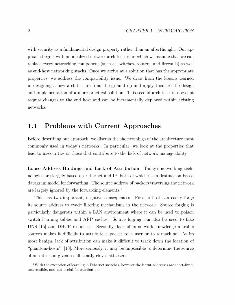
Internet architecture was born in a far more innocent era, when there was little need
to consider how to defend against malicious attacks. Many of the Internet’s primary
design goals that were so critical to its success, such as universal connectivity and
decentralized control, are now at odds with security.
Worms, malware, and sophisticated attackers mean that security can no longer be
ignored. This is particularly true for enterprise networks, where it is unacceptable to
lose data, expose private information, or lose system availability. Security measures
have been retrofitted to enterprise networks via many mechanisms, including router
ACLs, firewalls, NATs, and middleboxes, along with complex link-layer technologies
such as VLANs.
Despite years of experience and experimentation, these mechanisms remain far
from ideal and have created a management nightmare. Requiring a significant amount
of configuration and oversight [58], they are often limited in the range of policies
that they can enforce [63] and produce networks that are complex [67] and brittle
[68]. Moreover, even with these techniques, security within the enterprise remains
notoriously poor. Worms routinely cause significant losses in productivity [18] and
increase potential for data loss [44, 49]. Attacks resulting in theft of intellectual
property and other sensitive information are also common [32].
The long and largely unsuccessful struggle to protect enterprise networks con-
vinced us to start over with a clean slate. We aim to design manageable networks
1
2 CHAPTER 1. INTRODUCTION
with security as a fundamental design property rather than an afterthought. Our ap-
proach begins with an idealized network architecture in which we assume that we can
replace every networking component (such as switches, routers, and firewalls) as well
as end-host networking stacks. Once we arrive at a solution that has the appropriate
properties, we address the compatibility issue. We draw from the lessons learned
in designing a new architecture from the ground up and apply them to the design
and implementation of a more practical solution. This second architecture does not
require changes to the end host and can be incrementally deployed within existing
networks.
1.1 Problems with Current Approaches
Before describing our approach, we discuss the shortcomings of the architecture most
commonly used in today’s networks. In particular, we look at the properties that
lead to insecurities or those that contribute to the lack of network manageability.
Loose Address Bindings and Lack of Attribution Today’s networking tech-
nologies are largely based on Ethernet and IP, both of which use a destination based
datagram model for forwarding. The source address of packets traversing the network
are largely ignored by the forwarding elements.1
This has two important, negative consequences. First, a host can easily forge
its source address to evade filtering mechanisms in the network. Source forging is
particularly dangerous within a LAN environment where it can be used to poison
switch learning tables and ARP caches. Source forging can also be used to fake
DNS [15] and DHCP responses. Secondly, lack of in-network knowledge a traffic
sources makes it difficult to attribute a packet to a user or to a machine. At its
most benign, lack of attribution can make it difficult to track down the location of
“phantom-hosts” [13]. More seriously, it may be impossible to determine the source
of an intrusion given a sufficiently clever attacker.
1With the exception of learning in Ethernet switches, however the learnt addresses are short-lived,inaccessible, and not useful for attribution.
1.1. PROBLEMS WITH CURRENT APPROACHES 3
Complexity of Mechanism A typical enterprise network today uses several mech-
anisms simultaneously to protect its network: VLANs, ACLs, firewalls, NATs, and so
on. The security policy is distributed among the boxes that implement these mech-
anisms, making it difficult to correctly implement an enterprise-wide security policy.
Configuration is complex; for example, routing protocols often require thousands of
lines of policy configuration [68]. Furthermore, the configuration is often dependent
on network topology and based on addresses and physical ports, rather than on au-
thenticated end-points. When the topology changes or hosts move, the configuration
frequently breaks, requires careful repair [68], and potentially undermines its security
policies.
A common response is to put all security policy in one box and at a choke-point
in the network, for example, in a firewall at the network’s entry and exit points. If
an attacker makes it through the firewall, then they will have unfettered access to
the whole network. Another way to address this complexity is to enforce protection
of the end host via distributed firewalls [24]. While reasonable, this places all trust
in the end hosts. End host firewalls can be disabled or bypassed, leaving the net-
work unprotected, and they offer no containment of malicious infrastructure, e.g., a
compromised NIDS [17].
Proliferation of Trust Today’s networks provide a fertile environment for the
skilled attacker. Switches and routers must correctly export link state, calculate
routes, and perform filtering; over time, these mechanisms have become more com-
plex, with new vulnerabilities discovered at an alarming rate [17, 19, 16, 20]. If
compromised, an attacker can take down the network [47, 66] or redirect traffic to
permit eavesdropping, traffic analysis, and man-in-the-middle attacks.
Proliferation of Information Another resource for an attacker is the proliferation
of information on the network layout of today’s enterprises. This knowledge is valu-
able for identifying sensitive servers, firewalls, and IDS systems that can be exploited
for compromise or denial of service. Topology information is easy to gather: switches
and routers keep track of the network topology (e.g., the OSPF topology database)
4 CHAPTER 1. INTRODUCTION
and broadcast it periodically in plain text. Likewise, host enumeration (e.g., ping and
ARP scans), port scanning, traceroutes, and SNMP can easily reveal the existence
of, and the route to, hosts. Today, it is common for network operators to filter ICMP
and disable or change default SNMP passphrases to limit the amount of information
available to an intruder. As these services become more difficult to access, however,
the network becomes more difficult to diagnose.
1.2 Solution Requirements
In addition to retaining the characteristics that have resulted in the wide deployment
of IP and Ethernet networks – simple use model, suitable (e.g., Gigabit) performance,
the ability to scale to support large organizations, and robustness aand adaptability to
failure – a solution should address the deficiencies addressed in the previous section.
In particular, a security management architecture solution should conform to the
following central design principles.
• The network should be managed from a single global security policy declared
over mnemonic names. We seek an architecture that supports natural poli-
cies that are independent of the topology and the equipment used e.g., “allow
everyone in group sales to connect to the http server through a web proxy.”.
This contrasts with todays policies, which are typically expressed in terms of
topology-dependent ACLs in firewalls. Through high-level policies, our goal is
to provide access control that is restrictive (i.e. provides least privilege access to
resources) yet flexible, so that the network does not become unusable. Through
logical centralization, we avoid the distributed maintenance problems that are
legion with todays firewalls and ACL configuration files[64].
• Policy should determine the path that packets follow. There are several reasons
for policy to dictate the paths. First, policy might require that packets pass
through an intermediate middlebox; for example, a guest user might be required
to communicate via a proxy, or the user of an unpatched operating system might
be required to communicate via an intrusion detection system [4, 9]. Second,
1.2. SOLUTION REQUIREMENTS 5
traffic can receive more appropriate service if its path is controlled. Directing
real-time communications over lightly loaded paths, important communications
over redundant paths, and private communications over paths inside a trusted
boundary would lead to better service. Allowing the network manager to de-
termine the paths via policy–where the policy is in terms of high-level names–
leads to finer-level control and greater visibility than current designs.
• Minimize the trusted computing base. Today’s networks trust multiple com-
ponents, such as firewalls, switches, routers, DNS, and authentication services
(e.g., Kerberos, AD, and Radius). The compromise of any one component can
wreak havoc on the entire enterprise. Our goal is to reduce the trusted com-
puting base as much as possible; optimally, the architecture would gracefully
manage malicious switches.
• The network should enforce a strong binding between a packet and its origin. It
is difficult to reliably determine the origin of a packet: addresses are dynamic,
change frequently, and are easily manipulated. As eluded to in the previous
section, the loose binding between users and their traffic is a constant target for
attacks in enterprise networks. If the network is governed by a policy declared
over high-level names (e.g., users and hosts), then packets should be identifiable
as coming from a particular physical entity. This requires a strong binding
between a user, the machine they are using, and the addresses in the packets
that they generate. This binding must be kept consistent at all times by tracking
users and machines as they move.
• Authenticated diagnostics. In order to further an attack from a compromised
machine, an attacker will often map out the network’s topology to identify fire-
walls, critical servers, and the location of end hosts as well as to identify end
hosts and services that can be compromised. This reconnaissance is often ac-
complished using the network’s own diagnostic tools, such as SNMP or ICMP.
Turning off such features makes the network opaque to administrators. Rather
than require a trade-off between security and diagnostic transparency, the net-
work should treat network information as it would any other resource and allow
6 CHAPTER 1. INTRODUCTION
access controls to be expressed over it.
1.2.1 Threat Environment
In the proposed architecture, we seek to provide protection robust enough for de-
manding threat environments, such as government and military networks, yet flexible
enough for everyday use. We assume a robust threat environment with both in-
sider (authenticated users or switches) and outsider threats (e.g., an unauthenticated
attacker plugging into a network jack). This attacker may be capable of compro-
mising infrastructure components and exploiting protocol weaknesses; consequently,
we assume that attacks can originate from any network element, such as end hosts,
switches, or firewalls.
Our goal is to prevent malicious end hosts from sending traffic anywhere that has
not been explicitly authorized or, if authorized, subjecting the network to a denial-
of-service attack that cannot be subsequently disabled. Our solution also makes an
attempt to maintain availability in the face of malicious switches. Attack resistance
is described in more detail in Section 2.3.
1.3 A Centralized, Default-Off Solution
In order to achieve the properties described in the previous section, we choose to build
our designs around a centralized control architecture. We feel that centralization is
the proper approach to build a secure and manageable network for the enterprise.
IP’s best effort service is both simple and unchanging, which makes it well-suited
for distributed algorithms. Network security management is quite the opposite: its
requirements are complex and require strong consistency, making it quite difficult to
compute in a distributed manner.
Both of the proposed architectures in this thesis are managed from a logically
centralized Controller. In our approach, rather than distributing policy declaration,
routing computation, and permission checks among the switches and routers, these
functions are all managed by the Controller. As a result, the switches are reduced
1.3. A CENTRALIZED, DEFAULT-OFF SOLUTION 7
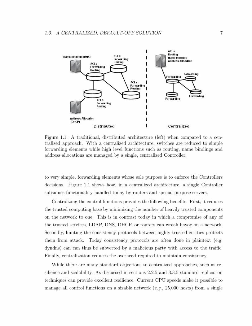
Figure 1.1: A traditional, distributed architecture (left) when compared to a cen-tralized approach. With a centralized architecture, switches are reduced to simpleforwarding elements while high level functions such as routing, name bindings andaddress allocations are managed by a single, centralized Controller.
to very simple, forwarding elements whose sole purpose is to enforce the Controllers
decisions. Figure 1.1 shows how, in a centralized architecture, a single Controller
subsumes functionality handled today by routers and special purpose servers.
Centralizing the control functions provides the following benefits. First, it reduces
the trusted computing base by minimizing the number of heavily trusted components
on the network to one. This is in contrast today in which a compromise of any of
the trusted services, LDAP, DNS, DHCP, or routers can wreak havoc on a network.
Secondly, limiting the consistency protocols between highly trusted entities protects
them from attack. Today consistency protocols are often done in plaintext (e.g.
dyndns) can can thus be subverted by a malicious party with access to the traffic.
Finally, centralization reduces the overhead required to maintain consistency.
While there are many standard objections to centralized approaches, such as re-
silience and scalability. As discussed in sections 2.2.5 and 3.3.5 standard replication
techniques can provide excellent resilience. Current CPU speeds make it possible to
manage all control functions on a sizable network (e.g., 25,000 hosts) from a single
8 CHAPTER 1. INTRODUCTION
commodity PC.
Another design choice was to make the network “off-by-default” [22]. That is,
by default, hosts on the network cannot communicate with each other; they can
only route to the network Controller. Hosts and users must first authenticate them-
selves with the Controller before they can request access to the network resources
and, ultimately, to other end hosts. Allowing the Controller to interpose on each
communication allows strict control over all network flows. In addition, requiring
authentication of all network principles (hosts and users) allows control to be defined
over high level names in a secure manner.
At first glance, our approach may seem draconian, as all communication requires
the permission of a central administrator. In practice, however, the administrator is
free to implement a wide variety of policies that vary from strict to relaxed and differ
among users and services. The key is that our approach allows easy implementation
and enforcement through centralization of a simply expressed network security policy.
1.4 Why Focus on the Enterprise?
Now that we have described our solution requirements and general architectural de-
sign philosophy, we discuss the reasons why the enterprise is a prime candidate for
such an architecture.
First, enterprise networks are often carefully engineered and centrally adminis-
tered, making it practical (and desirable) to implement policies in a central location.2
Moreover, most machines in enterprise networks are clients that typically contact a
predictable handful of local services (e.g., mail servers, printers, file servers, source
repositories, HTTP proxies, or ssh gateways). Therefore, we can grant relatively little
privilege to clients using simple declarative access control policies.
Furthermore, in an enterprise network, we can assume that hosts and principals are
authenticated; this is already common today with widely deployed directory services
such as LDAP [61] and Active Directory. This allows us to express policies in terms
of meaningful entities, such as hosts and users, instead of weakly bound end-point
2A policy might be specified by many people (e.g, LDAP), but is typically centrally managed.
1.5. PREVIOUS WORKS 9
identifiers, such as IP and MAC addresses.
Finally, enterprise networks compared to the Internet at large can quickly adopt a
new protection architecture. Fork-lift upgrades of entire networks are not uncommon,
and new networks are regularly built from scratch. Further, there is a significant
willingness to adopt new security technologies due to the high cost of security failures.
1.5 Previous Works
Network Protection Mechanisms Firewalls have been the cornerstone of enter-
prise security for many years. However, their use is largely restricted to enforcing
coarse-grain network perimeters [63]. Even in this limited role, misconfiguration has
been a persistent problem [64, 65]. This can be attributed to several factors; in
particular, their low-level policy specification and highly localized view leaves fire-
walls highly sensitive to changes in topology. A variety of efforts have examined less
error prone methods for policy specification [23] and how to detect policy errors
automatically [48].
The desire for a mechanism that supports ubiquitous enforcement, topology inde-
pendence, centralized management, and meaningful end-point identifiers has led to
the development of distributed firewalls [24, 40, 43]. Distributed firewalls approach
this problem with a centralized authority that manages the firewall rules for all end
hosts. While this provides centralized and topology independent policy, it is based
on substantially different trust and usage models of the network. First, it requires
that some software be installed on the end host. This can be beneficial as it provides
greater visibility into end host behavior, but it comes at the cost of convenience. More
importantly, for end hosts to perform enforcement, the end host must be trusted (or
at least some part of it, e.g., the OS [40], a VMM [36], the NIC [46], or some small
peripheral [55]). Furthermore, in a distributed firewall scenario, the network infras-
tructure itself receives no protection, i.e., the network is still allows connectivity by
default. This design affords no defense-in-depth if the end-point firewall is bypassed,
as it leaves all other network elements exposed.
10 CHAPTER 1. INTRODUCTION
Weaver et al. [63] argue that existing configurations of coarse-grain network perime-
ters (e.g., NIDS and multiple firewalls) and end host protective mechanisms (e.g. anti-
virus software) are ineffective against worms when employed individually or in combi-
nation. They advocate augmenting traditional coarse-grain perimeters with fine-grain
protection mechanisms throughout the network, especially to detect and halt worm
propagation.
Commercial Offerings There are a number of Identity-Based Networking (IBN)
solutions available in the industry. However, most lack control of the datapath [7],
are passive [12, 11], or require modifications to the end-hosts [2].
Consentry [5] creates special-purpose bridges for enforcing access control policy.
To our knowledge, these solutions require that the bridges are placed at a choke point
in the network, so that all traffic needing enforcement passes through them. This is
a potential single point of failure and performance bottleneck.
Ipsilon Networks proposed caching IP routing decisions as flows [51]. The goal was
to provide a switched, multi-service fast path to traditional IP routers. Ethane also
uses flows as a forwarding primitive. However, Ethane extends forwarding to include
functionality useful for enforcing security, such as address swapping and enforcing
outgoing initiated flows only.
VLANs are widely used in enterprise networks for segmentation, isolation, and
enforcement of course-grain policies; they are commonly used to quarantine unau-
thenticated hosts or hosts without health certificates [9, 4]. VLANs are notoriously
difficult to use, requiring much hand-holding and manual configuration. Our goal is
to replace VLANs entirely in a unified architecture that gives much simpler control
over isolation, connectivity, and diagnostics.
Dealing with Routing Complexity Often misconfigured routers make firewalls
simply irrelevant by routing around them. The inability to answer simple reachabil-
ity questions in todays enterprise networks has fueled commercial offerings such as
those of Lumeta [8] to help administrators discover what connectivity exists in their
network.
1.6. ORGANIZATION OF THESIS 11
In their 4D architecture, Rexford et al. [56, 38, 70] argue that the decentralized
routing policy, access control, and management has resulted in complex routers and
cumbersome, difficult-to-manage networks. Similar to our approach, they argue that
routing (the control plane) should be separated from forwarding, resulting in a very
simple data path. Although 4D centralizes routing policy decisions, they retain the
security model of today’s networks. Routing (forwarding tables) and access controls
(filtering rules) are still decoupled, disseminated to forwarding elements, and operate
the basis of weakly-bound end-point identifiers (IP addresses).
Predicate routing [58] attempts to unify security and routing by defining con-
nectivity as a set of declarative statements from which routing tables and filters are
generated. In contrast, our goal is to make users first-class objects, as opposed to
end-point IDs or IP addresses, that can be used to define access controls.
1.6 Organization of Thesis
This first chapter described the current problem with security management in en-
terprise networks. In brief, networks were not designed with security as a primary
design objective. Worse yet, post-facto solutions to add security management and
enforcement have been largely counterproductive, resulting in greater complexity,
architectural deficiencies such as choke points, and failure to provide strong assur-
ances. We propose a default-off, centralized architecture in which a global policy file
dictates all communications. A logically centralized controller contains the network
policy and manages principle authentication, permission checks, and routing, thus
providing complete control of the network.
In the rest of this thesis, we describe two concrete instantiations of this archi-
tecture and show that they not only provide strong security guarantees and simple
management but do so without compromising robustness to failure or performance.
In Chapter 2, we present SANE [29], a clean-slate approach to security management.
SANE is strictly a security-centric architecture designed to provide strong guarantees
in the most extreme threat environments. The mechanisms used by SANE would
require a wholesale upgrade of the router and switches within a network as well as
12 CHAPTER 1. INTRODUCTION
changes to the end hosts. Thus, SANE is largely a theoretical proposal intended
to illustrate the properties of an ideal security management architecture. When de-
signing SANE, we explicitly opted not to build backwards compatibility into the
architecture but rather, as is described in section 2.2.4, to support it using special
purpose components.
To address the deployment hurdles presented by SANE and to challenge some
of its usability assumptions, we offer a second architecture, Ethane [28], presented in
Chapter 3. In contrast with SANE, Ethane does not require modification to end-hosts
and can be incrementally deployed into existing networks for incremental benefit. We
describe the design and implementation of Ethane as well as our experience deploy-
ing and managing Ethane within an operational network. We also discuss how our
experience running an Ethane network informed its design.
Chapter 2
SANE: An Idealized Architecture
2.1 Introduction
In this chapter we describe SANE a clean-slate architecture which addresses the so-
lution requirements described in the first chapter. SANE achieves these goals by
providing a single protection layer that resides between the Ethernet and IP layer,
similar to the place that VLANs occupy. All connectivity is granted by handing out
capabilities. A capability is an encrypted source route between any two communicat-
ing end points.
Source routes are constructed by the Controller. By granting access using a global
vantage point, the Controller can implement policies in a topology-independent man-
ner. This is in contrast to today’s networks: the rules in firewalls and other middle-
boxes have implicit dependencies on topology, which become more complex as the
network and policies grow (e.g. VLAN tagging and firewall rules) [24, 65].
2.2 System Architecture
SANE ensures that network security policies are enforced during all end host commu-
nication at the link layer, as shown in Figure 2.1. This section describes two versions
of the SANE architecture. First, we present a clean-slate approach, in which every
network component is modified to support SANE. Later, we describe a version of
13
14 CHAPTER 2. SANE: AN IDEALIZED ARCHITECTURE
Figure 2.1: The SANE Service Model: By default, SANE only allows hosts to com-municate with the Controller. To obtain further connectivity they must take thefollowing steps: (0) Principals authenticate to the Controller and establish a securechannel for future communication. (1) Server B publishes a service under a uniquename B.http in the Network Service Directory. (2) For a client A to get permis-sion to access B.http, it obtains a capability for the service. (3) Client A can nowcommunicate with server by prepending the returned capability to each packet.
.
SANE that can inter-operate with unmodified end hosts running standard IP stacks.
2.2.1 Controller
The Controller is the central component of a SANE network. It is responsible for
authenticating users and hosts, advertising services that are available, and deciding
who can connect to these services. It allows hosts to communicate by handing out
capabilities (encrypted source routes). As we will see in Section 2.2.5, because the
network depends on it, the Controller will typically be physically replicated (described
in Section 2.2.5).
The Controller performs three main functions:
1. Authentication Service: This service authenticates principals (e.g., users,
2.2. SYSTEM ARCHITECTURE 15
Figure 2.2: Packets forwarded from client A to server B across multiple switchesusing a source-routed capability. Each layer contains the next-hop information, en-crypted to the associated switch’s symmetric key. The capability is passed to A bythe Controller (not shown) and can be re-used to send packets to B until it expires.
Ethernet SANE header IP header data
Figure 2.3: SANE operates at the same layer as VLAN. All packets on the networkmust carry a SANE header at the isolation layer, which strictly defines the path thatpacket is allowed to take.
hosts) and switches. It maintains a symmetric key with each for secure com-
munication.1
2. Network Service Directory (NSD): The NSD replaces DNS. When a princi-
pal wants access to a service, it first looks up the service in the NSD (services are
published by servers using a unique name). The NSD checks for permissions—
it maintains an access control list (ACL) for each service—and then returns a
capability. The ACL is declared in terms of system principals (users, groups),
mimicking the controls in a file system.
3. Protection Layer Controller: This component controls all connectivity in
a SANE network by generating (and revoking) capabilities. A capability is a
switch-level source route from the client to a server, as shown in Figure 2.2. Ca-
pabilities are encrypted in layers (i.e., onion routes [37]) both to prove that they
originated from the Controller and to hide topology. Capabilities are included
1SANE is agnostic to the PKI or other authentication mechanism in use (e.g. Kerberos, IBE).Here, we will assume principals and switches have keys that have been certified by the enterprisesCA.
16 CHAPTER 2. SANE: AN IDEALIZED ARCHITECTURE
in a SANE header in all data packets. The SANE header goes between the
Ethernet and IP headers, similar to the location VLANs occupy (Figure 2.3).
The controller keeps a complete view of the network topology so that it can
compute routes. The topology is constructed on the basis of link-state updates
generated by authenticated switches. Capabilities are created using the sym-
metric keys (to switches and hosts) established by the authentication service.
The controller will adapt the network when things go wrong (maliciously or
otherwise). For example, if a switch floods the Controller with control traffic
(e.g. link-state updates), it will simply eliminate the switch from the network by
instructing its immediate neighbor switches to drop all traffic from that switch.
It will issue new capabilities so that ongoing communications can start using
the new topology.
All packet forwarding is done by switches, which can be thought of as simplified
Ethernet switches. Switches forward packets along the encrypted source route carried
in each packet. They also send link-state updates to the Controller so that it knows
the network topology.
Note that, in a SANE network, IP continues to provide wide-area connectivity as
well as a common framing format to support the use of unmodified end hosts. Yet
within a SANE enterprise, IP addresses are not used for identification, location, nor
routing.
2.2.2 Network Service Directory
The NSD maintains a hierarchy of directories and services; each directory and service
has an access control list specifying which users or groups can view, access, and
publish services, as well as who can modify the ACLs. This design is similar to that
deployed in distributed file systems such as AFS [39].
As an example usage scenario, suppose martin wants to share his MP3’s with his
friends aditya, mike, and tal in the high performance networking group. He sets up
a streaming audio server on his machine bongo, which has a directory
2.2. SYSTEM ARCHITECTURE 17
stanford.hpn.martin.friends with ACLs already set to allow his friends to list
and acquire services. He publishes his service by adding the command
sane --publish stanford.martin.ambient:31337
to his audio server’s startup script, and, correspondingly, adds the command
sane --remove stanford.martin.ambient
to its shutdown script. When his streaming audio server comes on line, it publishes
itself in the NSD as ambient. When tal accesses this service, he simply directs his
MP3 player to the name stanford.martin.ambient The NSD resolves the name
(similar to DNS), has the Controller issue a capability, and returns this capability,
which tal’s host then uses to access the audio server on bongo.
There is nothing unusual about SANE’s approach to access control. One could
envision replacing or combining SANE’s simple access control system with a more
sophisticated trust-management system [25], in order to allow for delegation, for
example. For most purposes, however, we believe that our current model provides a
simple yet expressive method of controlling access to services.
2.2.3 Protection Layer
All packets in a SANE network contain a SANE header located between the Ethernet
and IP headers. In Figure 2.4, we show the packet types supported in SANE, as well
as their intended use (further elaborated below).
Communicating with the Controller SANE establishes default connectivity to
the Controller by building a minimum spanning tree (MST), with the Controller
as the root of the tree. This is done using a standard distance vector approach
nearly identical to that used in Ethernet switches [1], with each switch sending HELLO
messages to its neighbor, indicating its distance from the root. The MST algorithm
18 CHAPTER 2. SANE: AN IDEALIZED ARCHITECTURE
HELLO Payload
Controller Request Capability Authenticator Payload
FORWARD Cap-ID Cap-Exp Capability Payload
REVOKE Cap-ID Cap-Exp SignatureController
Figure 2.4: Packet types in a SANE network: HELLO packets are used for immediateneighbor discovery and thus are never forwarded. Controller packets are used byend hosts and switches to communicate with the Controller; they are forwarded byswitches to the Controller along a default route. FORWARD packets are used for mosthost-to-host data transmissions; they include an encrypted source route (capability)which tells switches where to forward the packet. Finally, REVOKE packets revoke acapability before its normal expiration; they are forwarded back along a capability’sforward route.
has the property that no switch learns the network topology nor is the topology
reproducible from packet traces.
The spanning tree is only used to establish default routes for forwarding packets
to the Controller. We also need a mechanism for the Controller to communicate back
with switches so as to establish symmetric keys, required both for authentication and
for generating and decoding capabilities. Note that the Controller can initially only
communicate with its immediate neighbors, since it does not know the full topology.
The Controller first establishes shared keys with its direct neighbors, and it re-
ceives link-state updates from them. It then iteratively contacts switches at increasing
distances (hop-counts), until it has established shared keys with all switches to obtain
a map of the full topology.2 To contact a switch multiple hops away, the Controller
must first generate a capability given the topology information collected thus far.
Once established, keys provide confidentiality, integrity, and replay defense for all
subsequent traffic with the Controller via an authenticator header, much like IPsec’s
esp header.
All capability requests and link state updates—packets of type Controller—are
sent along the MST. As packets traverse the MST, the switches construct a request
capability3 by generating an encrypted onion at each hop containing the previous and
2To establish shared keys, we opt for a simple key-exchange protocol from the ike2 [42] suite.3Request capabilities are similar to network capabilities as discussed in [21, 69]
2.2. SYSTEM ARCHITECTURE 19
next hop, encrypted under the switch’s own key. The Controller uses the request
capabilities to communicate back to each sender. Because these capabilities encode
the path, the Controller can use them to determine the location of misbehaving
senders.
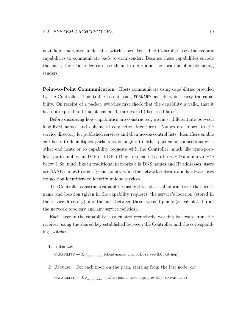
Point-to-Point Communication Hosts communicate using capabilities provided
by the Controller. This traffic is sent using FORWARD packets which carry the capa-
bility. On receipt of a packet, switches first check that the capability is valid, that it
has not expired and that it has not been revoked (discussed later).
Before discussing how capabilities are constructed, we must differentiate between
long-lived names and ephemeral connection identifiers. Names are known to the
service directory for published services and their access control lists. Identifiers enable
end hosts to demultiplex packets as belonging to either particular connections with
other end hosts or to capability requests with the Controller, much like transport-
level port numbers in TCP or UDP. (They are denoted as client-ID and server-ID
below.) So, much like in traditional networks a la DNS names and IP addresses, users
use SANE names to identify end-points, while the network software and hardware uses
connection identifiers to identify unique services.
The Controller constructs capabilities using three pieces of information: the client’s
name and location (given in the capability request), the service’s location (stored in
the service directory), and the path between these two end-points (as calculated from
the network topology and any service policies).
Each layer in the capability is calculated recursively, working backward from the
receiver, using the shared key established between the Controller and the correspond-
ing switches.
1. Initialize:
capability ← EKserver−name (client-name, client-ID, server-ID, last-hop)
2. Recurse: For each node on the path, starting from the last node, do:
capability ← EKswitch−name (switch-name, next-hop, prev-hop, capability)
20 CHAPTER 2. SANE: AN IDEALIZED ARCHITECTURE
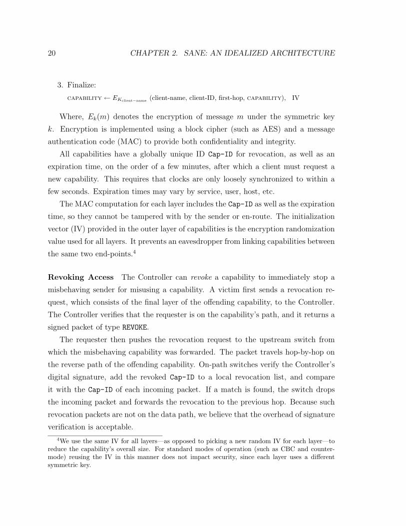
3. Finalize:
capability ← EKclient−name (client-name, client-ID, first-hop, capability), IV
Where, Ek(m) denotes the encryption of message m under the symmetric key
k. Encryption is implemented using a block cipher (such as AES) and a message
authentication code (MAC) to provide both confidentiality and integrity.
All capabilities have a globally unique ID Cap-ID for revocation, as well as an
expiration time, on the order of a few minutes, after which a client must request a
new capability. This requires that clocks are only loosely synchronized to within a
few seconds. Expiration times may vary by service, user, host, etc.
The MAC computation for each layer includes the Cap-ID as well as the expiration
time, so they cannot be tampered with by the sender or en-route. The initialization
vector (IV) provided in the outer layer of capabilities is the encryption randomization
value used for all layers. It prevents an eavesdropper from linking capabilities between
the same two end-points.4
Revoking Access The Controller can revoke a capability to immediately stop a
misbehaving sender for misusing a capability. A victim first sends a revocation re-
quest, which consists of the final layer of the offending capability, to the Controller.
The Controller verifies that the requester is on the capability’s path, and it returns a
signed packet of type REVOKE.
The requester then pushes the revocation request to the upstream switch from
which the misbehaving capability was forwarded. The packet travels hop-by-hop on
the reverse path of the offending capability. On-path switches verify the Controller’s
digital signature, add the revoked Cap-ID to a local revocation list, and compare
it with the Cap-ID of each incoming packet. If a match is found, the switch drops
the incoming packet and forwards the revocation to the previous hop. Because such
revocation packets are not on the data path, we believe that the overhead of signature
verification is acceptable.
4We use the same IV for all layers—as opposed to picking a new random IV for each layer—toreduce the capability’s overall size. For standard modes of operation (such as CBC and counter-mode) reusing the IV in this manner does not impact security, since each layer uses a differentsymmetric key.
2.2. SYSTEM ARCHITECTURE 21
A revocation is only useful during the lifetime of its corresponding capability
and therefore carries the same expiration time. Once a revocation expires, it is
purged from the switch. We discuss protection against revocation state exhaustion
in section 2.3.1.
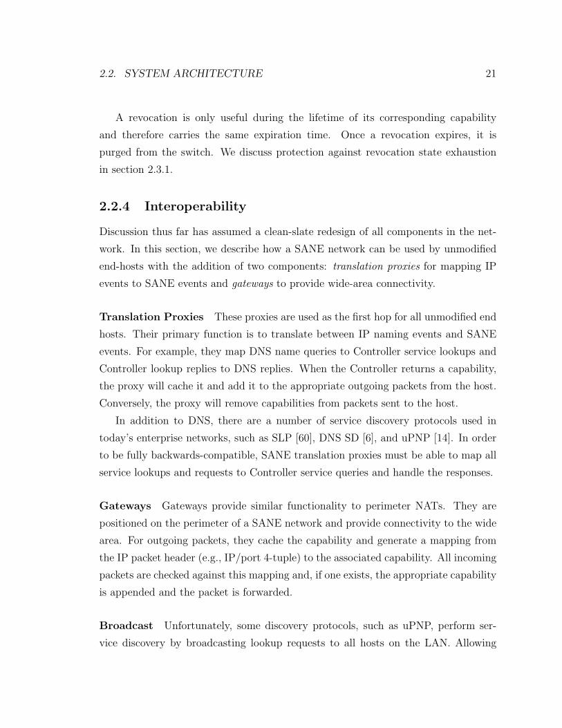
2.2.4 Interoperability
Discussion thus far has assumed a clean-slate redesign of all components in the net-
work. In this section, we describe how a SANE network can be used by unmodified
end-hosts with the addition of two components: translation proxies for mapping IP
events to SANE events and gateways to provide wide-area connectivity.
Translation Proxies These proxies are used as the first hop for all unmodified end
hosts. Their primary function is to translate between IP naming events and SANE
events. For example, they map DNS name queries to Controller service lookups and
Controller lookup replies to DNS replies. When the Controller returns a capability,
the proxy will cache it and add it to the appropriate outgoing packets from the host.
Conversely, the proxy will remove capabilities from packets sent to the host.
In addition to DNS, there are a number of service discovery protocols used in
today’s enterprise networks, such as SLP [60], DNS SD [6], and uPNP [14]. In order
to be fully backwards-compatible, SANE translation proxies must be able to map all
service lookups and requests to Controller service queries and handle the responses.
Gateways Gateways provide similar functionality to perimeter NATs. They are
positioned on the perimeter of a SANE network and provide connectivity to the wide
area. For outgoing packets, they cache the capability and generate a mapping from
the IP packet header (e.g., IP/port 4-tuple) to the associated capability. All incoming
packets are checked against this mapping and, if one exists, the appropriate capability
is appended and the packet is forwarded.
Broadcast Unfortunately, some discovery protocols, such as uPNP, perform ser-
vice discovery by broadcasting lookup requests to all hosts on the LAN. Allowing
22 CHAPTER 2. SANE: AN IDEALIZED ARCHITECTURE
this without intervention would be a violation of least privilege. To safely support
broadcast service discovery within SANE, all packets sent to the link-layer broadcast
address are forwarded to the Controller, which verifies that they strictly conform to
the protocol spec. The Controller then reissues the request to all end hosts on the
network, collects the replies and returns the response to the sender. Putting the Con-
troller on the path allows it to cache services for subsequent requests, thus having
the additional benefit of limiting the amount of broadcast traffic. Designing SANE
to efficiently support broadcast and multicast remains part of our future work.
Service Publication Within SANE, services can be published with the Controller
in any number of ways: translating existing service publication events (as described
above), via a command line tool, offering a web interface, or in the case of IP, hooking
into the bind call on the local host via SOCKS [45].
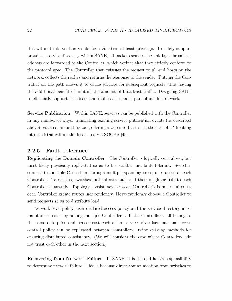
2.2.5 Fault Tolerance
Replicating the Domain Controller The Controller is logically centralized, but
most likely physically replicated so as to be scalable and fault tolerant. Switches
connect to multiple Controllers through multiple spanning trees, one rooted at each
Controller. To do this, switches authenticate and send their neighbor lists to each
Controller separately. Topology consistency between Controller’s is not required as
each Controller grants routes independently. Hosts randomly choose a Controller to
send requests so as to distribute load.
Network level-policy, user declared access policy and the service directory must
maintain consistency among multiple Controllers.. If the Controllers. all belong to
the same enterprise–and hence trust each other–service advertisements and access
control policy can be replicated between Controllers. using existing methods for
ensuring distributed consistency. (We will consider the case where Controllers. do
not trust each other in the next section.)
Recovering from Network Failure In SANE, it is the end host’s responsibility
to determine network failure. This is because direct communication from switches to
2.2. SYSTEM ARCHITECTURE 23
end hosts violates least privilege and creates new avenues for DoS. SANE-aware end
hosts send periodic probes or keep-alive messages to detect failures and request fresh
capabilities.
When a link fails, a Controller will be flooded with requests for new capabilities.
We performed a feasibility study (in Section 2.5), to see if this would be a problem
in practice, and found that even in the worst-case when all flows are affected, the
requests would not overwhelm a single Controller.
So that clients can adapt quickly, a Controller may issue multiple (edge-disjoint,
where possible) capabilities to clients. In the event of a link failure, a client simply
uses another capability. This works well if the topology is rich enough for there to be
edge-disjoint paths. Today’s enterprise networks are not usually richly interconnected,
in part because additional links and paths make security more complicated and easier
to undermine. However, this is no longer true with SANE—each additional switch
and link improves resilience. With just two or three alternate routes we can expect a
high degree of fault tolerance [41]. With multiple paths, an end host can set aggressive
time-outs to detect link failures (unlike in IP networks, where convergence times can
be high).
2.2.6 Additional Features
This section discusses some additional considerations of a SANE network, including
its support for middleboxes, mobility, and support for logging.
Middleboxes and Proxies In today’s networks, proxies are usually placed at
choke-points, to make sure traffic will pass through them. With SANE, a proxy can
be placed anywhere; the Controller can make sure the proxy is on the path between a
client and a server. This can lead to powerful application-level security policies that
far outreach port-level filtering.
At the very least, lightweight proxies can validate that communicating end-points
are adhering to security policy. Proxies can also enforce service- or user-specific
policies or perform transformations on a per-packet basis. These could be specified
24 CHAPTER 2. SANE: AN IDEALIZED ARCHITECTURE
by the capability. Proxies might scan for viruses and apply vulnerability-specific
filters, log application-level transactions, find information leaks, and shape traffic.
Mobility Client mobility within the LAN is transparent to servers, because the
service is unaware of (and so independent of) the underlying topology. When a client
changes its position—e.g., moves to a different wireless access point—it refreshes its
capabilities and passes new return routes to the servers it is accessing. If a client moves
locations, it should revoke its current set of outstanding capabilities. Otherwise, much
like today, a new machine plugged into the same access point could access traffic sent
to the client after it has left.
Server mobility is handled in the same manner as adapting to link failures. If
a server changes location, clients will detect that packets are not getting through
and request a new set of capabilities. Once the server has updated its service in the
directory, all (re)issued capabilities will contain the correct path.
Anti-mobility SANE also trivially anti-mobility. That is, SANE can prevent hosts
and switches from moving on the network by disallowing access if they do. As the
Controller knows the exact location of all senders given request capabilities, it can be
configured to only service hosts if they are connected at particular physical locations.
This is useful for regulatory compliance, such as 911 restrictions on movement for
VoIP-enabled devices. More generally, it allows a strong “lock-down” of network
entities to enforce strong policies in the highest-security networks. For example, it
can be used to disallow all network access to rogue PCs.
Centralized Logging The Controller, as the broker for all communications, is in
an ideal position for network-wide connection logging. This could be very useful
for forensics. Request routes protect against source spoofing on connection setup,
providing a path back to the connecting port in the network. Further, compulsory
authentication matches each connection request to an actual user.
What about IP? Note that, in a SANE network, IP continues to provide wide-
area connectivity as well as a common framing format to support the use of unmodified
2.3. ATTACK RESISTANCE 25
end hosts. Yet within a SANE enterprise, IP addresses are not used for identification,
location, nor routing.
2.3 Attack Resistance
SANE eliminates many of the vulnerabilities present in today’s networks through
centralization of control, simple declarative security policies and low-level enforcement
of encrypted source routes. In this section, we enumerate the main ways that SANE
resists attack.
• Access-control lists: The NSD uses ACLs for directories, preventing attack-
ers from enumerating all services in the system—an example of the principle
of least knowledge—which in turn prevents the discovery of particular applica-
tions for which compromises are known. The NSD controls access to services to
enforce protection at the link layer through Controller-generated capabilities—
supporting the principle of least privilege—which stops attackers from compro-
mising applications, even if they are discovered.
• Encrypted, authenticated source-routes and link-state updates: These
prevent an attacker from learning the topology or from enumerating hosts and
performing port scans, further examples of the principle of least knowledge.5
SANE’s source routes prevent hosts from spoofing requests either to the Con-
troller on the control path or to other end hosts on the data path. We discuss
these protections further in Section 2.3.1.
• Authenticated network components: The authentication mechanism pre-
vents unauthenticated switches from joining a SANE network, thwarting a va-
riety of topology attacks. Every switch enforces capabilities providing defence
in depth. Authenticated switches cannot lie about their connectivity to create
arbitrary links, nor can they use the same authenticated public key to join the
5For example, while SANE’s protection layer prevents an adversary from targeting arbitraryswitches, an attacker can attempt to target a switch indirectly by accessing an upstream server forwhich it otherwise has access permission.
26 CHAPTER 2. SANE: AN IDEALIZED ARCHITECTURE
network using different physical switches. Finally, well-known spanning-tree or
routing attacks [47, 66] are impossible, given the Controller’s central role. We
discuss these issues further in section 2.3.2.
SANE attempts to degrade gracefully in the face of more sophisticated attacks. Next,
we examine several major classes of attacks.
2.3.1 Resource Exhaustion
Flooding As discussed in section 2.2.3, flooding attacks are handled through re-
vocation. However, misbehaving switches or hosts may also attempt to attack the
network’s control path by flooding the Controller with requests. Thus, we rate-limit
requests for capabilities to the Controller. If a switch or end host violates the rate
limit, the Controller tells its neighbors to disconnect it from the network.
Revocation state exhaustion SANE switches must keep a list of revoked capabil-
ities. This list might fill, for example, if it is maintained in a small CAM. An attacker
could hoard capabilities, then cause all of them to be revoked simultaneously. SANE
uses two mechanisms to protect against this attack: (1) If its revocation list fills, a
switch simply generates a new key; this invalidates all existing capabilities that pass
through it. It clears its revocation list, and passes the new key to the Controller.
(2) The Controller tracks the number of revocations issued per sender. When this
number crosses a predefined threshold, the sender is removed from the service’s ACLs.
If a switch uses a sender’s capability to flood a receiver, thus eliciting a revocation,
the sender can use a different capability (if it has one) to avoid the misbehaving
switch. This occurs naturally because the client treats revocation—which results in
an inability to get packets through—as a link failure, and it will try using a different
capability instead. While well-behaved senders may have to use or request alternate
capabilities, their performance degradation is only temporary, provided that there
exists sufficient link redundancy to route around misbehaving switches. Therefore,
using this approach, SANE networks can quickly converge to a state where attackers
hold no valid capabilities and cannot obtain new ones.
2.3. ATTACK RESISTANCE 27
Figure 2.5: Attacker C can deny service to A by selectively dropping A’s packets,yet letting the packets of its parent (B) through. As a result, A cannot communicatewith the Controller, even though a alternate path exists through D.
2.3.2 Tolerating Malicious Switches
By design, SANE switches have minimal functionality—much of which is likely to be
placed in hardware—making remote compromise unlikely. Furthermore, each switch
requires an authenticated public key, preventing rogue switches from joining the net-
work. However, other avenues of attack, such as hardware tampering or supply-chain
attacks, may allow an adversary to introduce a malicious switch. For completeness,
therefore, we consider defenses against malicious switches attempting to sabotage
network operation, even though the following attacks are feasible only in the most
extreme threat environments.
Sabotaging MST Discovery By falsely advertising a smaller distance to the Con-
troller during MST construction, a switch can cause additional Controller traffic to
be routed through it. Nominally, this practice can create a path inefficiency.
More seriously, a switch can attract traffic, then start dropping packets. This
practice will result in degraded throughput, unless the drop rate increases to a point
at which the misbehaving switch is declared failed and a new MST is constructed.
In a more subtle attack, a malicious switch can selectively allow packets from
its neighbors, yet drop all other traffic. An example of this attack is depicted in
Figure 2.5: Node C only drops packets from node A. Thus, B does not change its for-
warding path to the Controller, as C appears to be functioning normal from its view.
As a result, A cannot communicate with the Controller, even though an alternate
path exists through D. Note that this attack, at the MST discovery phase, precludes
our normal solution for routing around failures—namely, using node-disjoint paths

28 CHAPTER 2. SANE: AN IDEALIZED ARCHITECTURE
whenever possible—as node A has never registered with the Controller in the first
place.
From a high level, we can protect against this selective attack by hiding the
identities of senders from switches en-route. Admittedly, it is unlikely that we can
prevent all such information leakage through the various side-channels that naturally
exist in a real system, e.g., due to careful packet inspection and flow analysis. Some
methods to confound such attacks include (1) hiding easily recognizable sender-IDs
from packet headers,6 (2) padding all response capabilities to the same length to hide
path length, and (3) randomizing periodic messages to the Controller to hide a node’s
scheduled timings.
Using these safeguards, if a switch drops almost all packets, its immediate neigh-
bors will construct a new MST that excludes it. If it only occasionally drops packets,
the rate of MST discovery is temporarily degraded, but downstream switches will
eventually register with the Controller.
Bad Link-State Advertisements Malicious switches can try to attract traffic by
falsifying connectivity information in link-state updates. A simple safeguard against
such attacks is for the Controller to only add non-leaf edges to its network map when
both switches at either end have advertised the link.
This safeguard does not prevent colluding nodes from falsely advertising a link
between themselves. Unfortunately, such collusion cannot be externally verified. No-
tice that such collusion can only result in a temporary denial-of-service attack when
capabilities containing a false link are issued: When end hosts are unable to route over
a false link, they immediately request a fresh capability. Additionally, the isolation
properties of the network are still preserved.
Note that SANE’s requirement for switches to initially authenticate themselves
with the Controller prevents Sybil attacks, normally associated with open identity-
free networks [35].
6Normally, Controller packet headers contain a consistent sender-ID in cleartext, much like theIPSec esp header. This sender-ID tells the Controller which key to use to authenticate and decryptthe payload. We replace this static ID with an ephemeral nonce provided by the Controller. EveryController response contains a new nonce to use as the sender-ID in the next message.
2.4. IMPLEMENTATION 29
2.3.3 Tolerating a Malicious Controller
Domain controllers are highly trusted entities in a SANE network. This can create
a single point-of-failure from a security standpoint, since the compromise of any one
Controller yields total control to an attacker.
To prevent such a take-over, one can distribute trust among Controllers using
threshold cryptography. While the full details are beyond the scope of this paper, we
sketch the basic approach. We split the Controllers’ secret key across a few servers (say
n < 6), such that two of them are needed to generate a capability. The sender then
communicates with 2-out-of-n Controllers to obtain the capability. Thus, an attacker
gains no additional access by compromising a single Controller.7 To prevent a single
malicious Controller from revoking arbitrary capabilities or, even worse, completely
disconnecting a switch or end host, the revocation mechanism (section 2.2.3) must
also be extended to use asymmetric threshold cryptography [34].
Given such replicated function, access control policy and service registration must
be done independently with each Controller by the end host, using standard ap-
proaches for consistency such as two-phase commit. When a new Controller comes
online or when a Controller re-establishes communication after a network partition, it
must have some means of re-syncing with the other Controllers. This can be achieved
via standard Byzantine agreement protocols [31].
2.4 Implementation
This section describes our prototype implementation of a SANE network. Our im-
plementation consists of a Controller, switches, and IP proxies. It does not support
multiple Controllers, there is no support for tolerating malicious switches nor were
any of the end-hosts instrumented to issue revocations.
All development was done in C++ using the Virtual Network System (VNS) [30].
VNS provides the ability to run processes within user-specified topologies, allowing
7Implementing threshold cryptography for symmetric encryption is done combinatorially [26]:Start from a t-out-of-t sharing (namely, encrypt a Controller master secret under all independentController server keys) and then construct a t-out-of-n sharing from it.
30 CHAPTER 2. SANE: AN IDEALIZED ARCHITECTURE
us to test multiple varied and complex network topologies while interfacing with
other hosts on the network. Working outside the kernel provided us with a flexible
development, debug, and execution environment.
The network was in operational use within our group LAN—interconnecting seven
physical hosts on 100 Mb Ethernet used daily as workstations—for one month. The
only modification needed for workstations was to reduce the maximum transmission
unit (MTU) size to 1300 bytes in order to provide room for SANE headers.
2.4.1 IP Proxies and SANE Switches
To support unmodified end hosts on our prototype network, we developed proxy
elements which are positioned between hosts and the first hop switches. Our proxies
use ARP cache poisoning to redirect all traffic from the end hosts. Capabilities for
each flow are cached at the corresponding proxies, which insert them into packets
from the end host and remove them from packets to the end host.
Our switch implementation supports automatic neighbor discovery, MST con-
struction, link-state updates and packet forwarding. Switches exchange HELLO mes-
sages every 15 seconds with their neighbors. Whenever switches detects network
failures, they reconfigure their MST and update the Controller’s network map.
The only dynamic state maintained on each switch is a hash table of capability
revocations, containing the Cap-IDs and their associated expiration times.
We use OCB-AES [57] for capability construction and decryption with 128-bit
keys. OCB provides both confidentiality and data integrity using a single pass over
the data, while generating ciphertext that is exactly only 8 bytes longer than the
input plaintext.
2.4.2 Controller
The Controller consists of four separate modules: the authentication service, the
network service directory, and the topology and capability construction service in
the Protection Layer Controller. For authentication purposes, the Controller was
preconfigured with the public keys of all switches.
2.4. IMPLEMENTATION 31
Capability construction For end-to-end path calculations when constructing ca-
pabilities, we use a bidirectional search from both the source and destination. All
computed routes are cached at the Controller to speed up subsequent capability re-
quests for the same pair of end hosts, although cached routes are checked against the
current topology to ensure freshness before re-use.
Capabilities use 8-bit IDs to denote the incoming and outgoing switch ports.
Switch IDs are 32 bits and the service IDs are 16 bits. The innermost layer of the
capability requires 24 bytes, while each additional layer uses 14 bytes. The longest
path on our test topologies was 10 switches in length, resulting in a 164 byte header.
Service Directory DNS queries for all unauthenticated users on our network re-
solve to the Controller’s IP address, which hosts a simple webserver. We provide a
basic HTTP interface to the service directory. Through a web browser, users can
log in via a simple web-form and can then browse the service directory or, with
the appropriate permissions, perform other operations (such as adding and deleting
services).
The directory service also provides an interface for managing users and groups.
Non-administrative users are able to create their own groups and use them in access-
control declarations.
To access a service, a client browses the directory tree for the desired service, each
of which is listed as a link. If a service is selected, the directory server checks the user’s
permissions. If successful, the Controller generates capabilities for the flows and sends
them to the client (or more accurately, the client’s SANE IP proxy). The web-server
returns an HTTP redirect to the service’s appropriate protocol and network address,
e.g., ssh://192.168.1.1:22/. The client’s browser can then launch the appropriate
application if one such is registered; otherwise, the user must do so by hand.
2.4.3 Example Operation
As a concrete example, we describe the events for an ssh session initiated within our
internal network. All participating end hosts have a translation proxy positioned
32 CHAPTER 2. SANE: AN IDEALIZED ARCHITECTURE
between them and the rest of the network. Additionally, they are configured so that
the Controller acts as their default DNS server.
Until a user has logged in, the translation proxy returns the Controller’s IP address
for all DNS queries and forwards all TCP packets sent to port 80 to the Controller.
Users opening a web-browser are therefore automatically forwarded to the Controller
so that they may log in. This is similar in feel to admission control systems employed
by hotels and wireless access points. All packets forwarded to the Controller are
accompanied by a SANE header which is added by the translation proxy. Once a
user has authenticated, the Controller caches the user’s location (derived from the
SANE header of the authentication packets) and associates all subsequent packets
from that location with the user.
Suppose a user ssh’s from machine A to machine B. A will issue a DNS request for
B. The translation proxy will intercept the DNS packet (after forging an ARP reply)
and translate the DNS requests to a capability request for machine B. Because the
the DNS name does not contain an indication of the service, by convention we prepend
the service name to the beginning of the DNS request (e.g. ssh ssh.B.stanford.edu).
The Controller does the permission check based on the capability (initially added by
the translation proxy) and the ACL of the requested service.
If the permission check is successful, the Controller returns the capabilities for
the client and server, which are cached at the translation proxy. The translation
proxy then sends a DNS reply to A with a unique destination IP address d, which
allows it to demultiplex subsequent packets. Subsequently, when the translation
proxy receives packets from A destined to d, it changes d to the destination’s true IP
address (much like a NAT) and tags the packet with the appropriate SANE capability.
Additionally, the translation proxy piggybacks the return capability destined for the
server’s translation proxy on the first packet. Return traffic from the server to the
client is handled similarly.
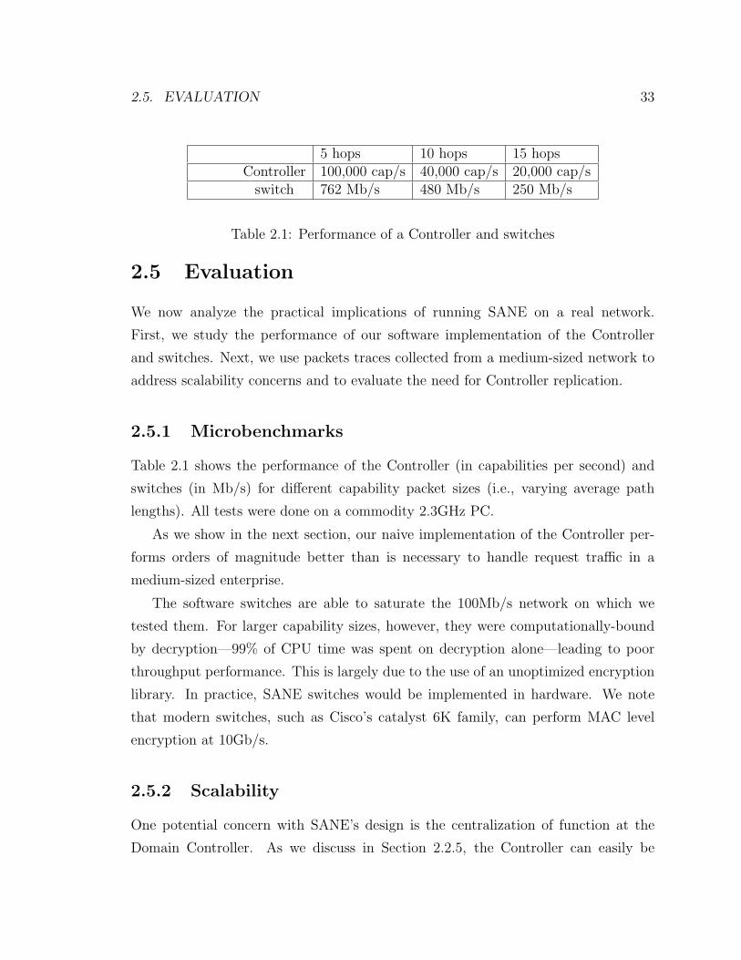
2.5. EVALUATION 33
5 hops 10 hops 15 hopsController 100,000 cap/s 40,000 cap/s 20,000 cap/s
switch 762 Mb/s 480 Mb/s 250 Mb/s
Table 2.1: Performance of a Controller and switches
2.5 Evaluation
We now analyze the practical implications of running SANE on a real network.
First, we study the performance of our software implementation of the Controller
and switches. Next, we use packets traces collected from a medium-sized network to
address scalability concerns and to evaluate the need for Controller replication.
2.5.1 Microbenchmarks
Table 2.1 shows the performance of the Controller (in capabilities per second) and
switches (in Mb/s) for different capability packet sizes (i.e., varying average path
lengths). All tests were done on a commodity 2.3GHz PC.
As we show in the next section, our naive implementation of the Controller per-
forms orders of magnitude better than is necessary to handle request traffic in a
medium-sized enterprise.
The software switches are able to saturate the 100Mb/s network on which we
tested them. For larger capability sizes, however, they were computationally-bound
by decryption—99% of CPU time was spent on decryption alone—leading to poor
throughput performance. This is largely due to the use of an unoptimized encryption
library. In practice, SANE switches would be implemented in hardware. We note
that modern switches, such as Cisco’s catalyst 6K family, can perform MAC level
encryption at 10Gb/s.
2.5.2 Scalability
One potential concern with SANE’s design is the centralization of function at the
Domain Controller. As we discuss in Section 2.2.5, the Controller can easily be
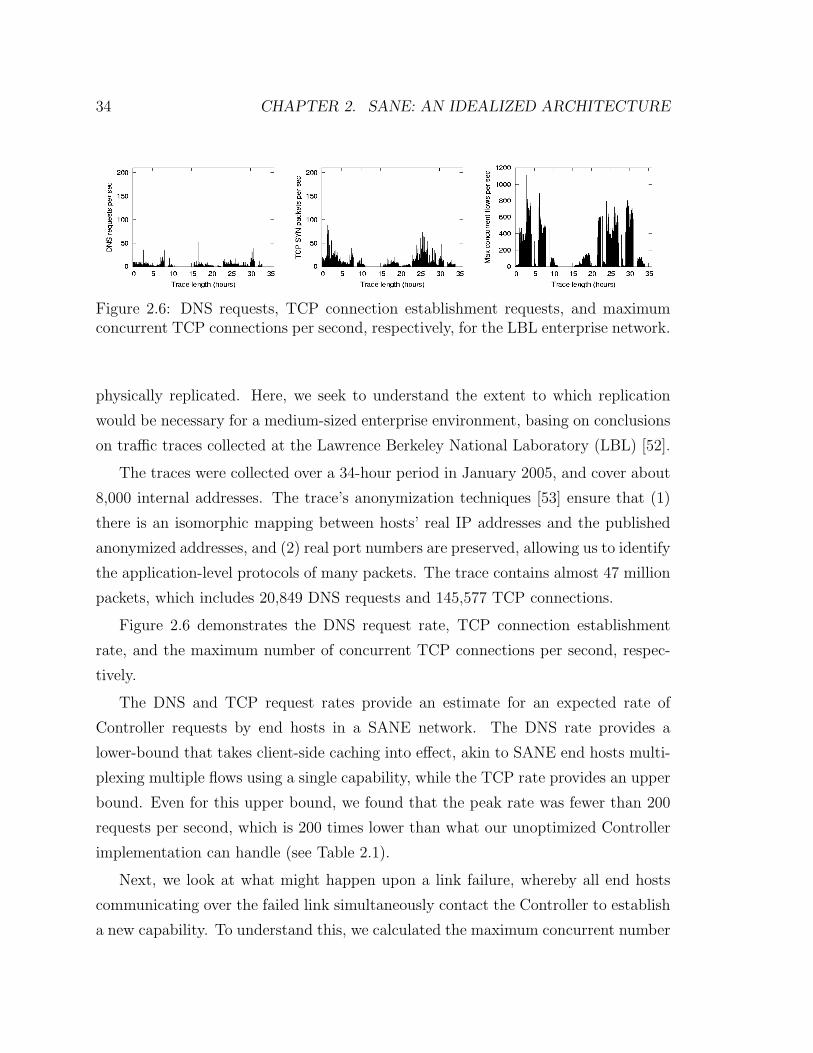
34 CHAPTER 2. SANE: AN IDEALIZED ARCHITECTURE
Figure 2.6: DNS requests, TCP connection establishment requests, and maximumconcurrent TCP connections per second, respectively, for the LBL enterprise network.
physically replicated. Here, we seek to understand the extent to which replication
would be necessary for a medium-sized enterprise environment, basing on conclusions
on traffic traces collected at the Lawrence Berkeley National Laboratory (LBL) [52].
The traces were collected over a 34-hour period in January 2005, and cover about
8,000 internal addresses. The trace’s anonymization techniques [53] ensure that (1)
there is an isomorphic mapping between hosts’ real IP addresses and the published
anonymized addresses, and (2) real port numbers are preserved, allowing us to identify
the application-level protocols of many packets. The trace contains almost 47 million
packets, which includes 20,849 DNS requests and 145,577 TCP connections.
Figure 2.6 demonstrates the DNS request rate, TCP connection establishment
rate, and the maximum number of concurrent TCP connections per second, respec-
tively.
The DNS and TCP request rates provide an estimate for an expected rate of
Controller requests by end hosts in a SANE network. The DNS rate provides a
lower-bound that takes client-side caching into effect, akin to SANE end hosts multi-
plexing multiple flows using a single capability, while the TCP rate provides an upper
bound. Even for this upper bound, we found that the peak rate was fewer than 200
requests per second, which is 200 times lower than what our unoptimized Controller
implementation can handle (see Table 2.1).
Next, we look at what might happen upon a link failure, whereby all end hosts
communicating over the failed link simultaneously contact the Controller to establish
a new capability. To understand this, we calculated the maximum concurrent number
2.5. EVALUATION 35
of TCP connections in the LBL network.8 We find that the dataset has a maximum
of 1,111 concurrent connections, while the median is only 27 connections. Assuming
the worst-case link failure—whereby all connections traverse the same network link
which fails—our simple Controller can still manage 40 times more requests.
Based on the above measurements, we estimate the bandwidth consumption of
control traffic on a SANE network. In the worst case, assuming no link failure, 200
requests per second are sent to the Controller. We assume all flows are long-lived, and
that refreshes are sent every 10 minutes. With 1,111 concurrent connections in the
worst case, capability refresh requests result in at most an additional 2 packets/s.9
Given header sizes in our prototype implementation and assuming the longest path
on the network to be 10 hops, packets carrying the forward and return capabilities
will be at most 0.4 KB in size, resulting in a maximum of 0.646 Mb/s of control
traffic.
This analysis of an enterprise network demonstrates that only a few domain con-
trollers are necessary to handle Controller requests from tens of thousands of end
hosts. In fact, Controller replication is probably more relevant to ensure uninter-
rupted service in the face of potential Controller failures.
8To calculate the concurrent number of TCP connections, we tracked srcip:srcport:dstip:dstporttuples, where a connection is considered finished upon receiving the first FIN packet or if no trafficpackets belonging to that tuple are seen for 15 minutes. There were only 143 cases of TCP packetsthat were sent after a connection was considered timed-out.
9This is a conservative upper bound: In our traces, the average flow length is 92s, implying thatat most, 15% of the flows could have lengths greater than 10 minutes.
Chapter 3
Ethane: A Deployable Architecture
3.1 Introduction
This chapter describes Ethane, a deployable alternative to SANE. As described
in 2.2.4, while it is possible to retrofit SANE into existing IP networks using event
translation proxies, this has two significant drawbacks. First, it would require con-
stant maintenance to track changes to end-host protocols. Second, the introduction
of the isolation layer, between the link and network layers, obviates integration with
existing IP routers.
To address these issues we designed a new architecture which contains many of
the same properties offered by SANE and without requiring changes to the end hosts.
Further, Ethane can be incrementally deployed within an existing network and has
full compatibility with existing IP routers.
While Ethane has substantial resemblance to SANE, it bears the following signif-
icant differences.
Security follows management. Enterprise security is, in many ways, a subset of
network management. Both require a network policy, the ability to control connec-
tivity, and the means to observe network traffic. Network management wants these
features so as to control and isolate resources, and then to diagnose and fix errors,
whereas network security seeks to control who is allowed to talk to whom, and then
36
3.1. INTRODUCTION 37
to catch bad behavior before it propagates. When designing Ethane, we decided that
a broad approach to network management would also work well for network security.
Modified Policy Model. In SANE, network policy is service oriented and enforced
through ACLs on a network directory service that operates similar to a file system.
While a familiar policy model in the context of file systems, today’s networks do
not contain named services. In addition to lack of compatibility, this departure from
traditional firewall declarations could present a usability hurdle to administrators. In
Ethane, we built support for a general policy language that governs all connectivity
via predicates declared over the users, hosts, access points and protocols. However,
the policy does not support named services.
Flow-Based. In Ethane, access is granted to hosts by explicitly setting up flows
within the network. This approach requires storing per-flow state at each switch. As
we show in section 3.6 the state requirements of today’s networks are such that even
large networks of tens of thousands of hosts can be supported by a single SRAM chip.
Further, explicitly defining the flows at the switches allows us to support sophisticated
forwarding functions to granted flows, such as rate limiting.
Significant deployment experience. Ethane has been implemented in both soft-
ware and hardware (special-purpose Gigabit Ethernet switches) and was deployed at
Stanford for over four months, managing over 300 hosts. This deployment experi-
ence provided us insight into the operational issues such a design must confront, and
resulted in significant changes and extensions to the original design.
Despite its differences, Ethane retains many of the same properties as SANE.
Like SANE, the Controller imposes permission checks per-flow and has control over
routes when granting access to communicate. Also like SANE, the policy is topology
independent, can restrict movement on the network, and is declared over high-level
names. Yet Ethane is practical. To demonstrate this, we built and deployed an
Ethane network within Stanford, and used it to manage traffic from roughly 300
hosts for over 4 months.
This chapter is organized as follows. In §3.2 we present a high-level overview of the
Ethane design, followed by a detailed description in §3.3. In §3.4, we describe a policy
38 CHAPTER 3. ETHANE: A DEPLOYABLE ARCHITECTURE
language Pol-Eth that we built to manage our Ethane implementation. We then dis-
cuss our implementation and deployment experience (§3.5), followed by performance
analysis (§3.6). Finally we present limitations in §3.7.
3.2 Overview of Ethane Design
Like SANE, Ethane controls the network by not allowing any communication between
end-hosts without explicit permission. Also like SANE, the network is broadly com-
posed into two main components. The first is then central Controller containing the
global network policy that determines the fate of all packets.
However, unlike in SANE, the Controller uses the first packet of each Flow for
connection setup. when a packet arrives at the Controller (how it does so is described
below), the Controller decides whether the flow represented by that packet1 should
be allowed. The Controller knows the global network topology and performs route
computation for permitted flows. It grants access by explicitly enabling flows within
the network switches along the chosen route. The Controller can be replicated for
redundancy and performance.
The second component is a set of Ethane Switches. In contrast to the omniscient
Controller, these Switches are simple and dumb. While SANE switches are simple
decryption engines with extra state for revocation, Ethane switches consist of a simple
flow-table which forwards packets under the direction of the Controller. When a
packet arrives that is not in the flow table, they forward that packet to the Controller
(in a manner we describe later), along with information about which port the packet
arrived on. When a packet arrives that is in the flow table, it is forwarded according
to the Controller’s directive. Not every switch in an Ethane network needs to be
an Ethane Switch – our design allows Switches to be added gradually; the network
becomes more manageable with each additional Switch.
1All policies considered in Ethane are based over flows—the header fields used to define a floware based on the packet type, for example TCP/UDP flows include the Ethernet, IP and transportheaders—and thus only a single policy decision need be made for each such “flow”.
3.2. OVERVIEW OF ETHANE DESIGN 39
3.2.1 Names, Bindings, and Policy Language
When the Controller checks a packet against the global policy, it is evaluating the
packet against a set of simple rules, such as “Guests can communicate using HTTP,
but only via a web proxy” or “VoIP phones are not allowed to communicate with
laptops.” If we want the global policy to be specified in terms of such physical
entities, we need to reliably and securely associate a packet with the user, group,
or machine that sent it. If the mappings between machine names and IP addresses
(DNS) or between IP addresses and MAC addresses (ARP and DHCP) are handled
elsewhere and are unreliable, then we cannot possibly tell who sent the packet, even if
the user authenticates with the network. This is a notorious and widespread weakness
in current networks.
With (logical) centralization it is simple to keep the namespace consistent, as
components join, leave and move around the network. Network state changes simply
require updating the bindings at the Controller. This is in contrast to today’s network
where there are no widely used protocols for keeping this information consistent.
Further, distributing the namespace among all switches would greatly increase the
trusted computing base and require high overheads to maintain consistency on each
bind event.
In Ethane, we use a sequence of techniques to secure the bindings between packet
headers and the physical entities that sent them. First, Ethane takes over all the
binding of addresses. When machines use DHCP to request an IP address, Ethane
assigns it knowing to which switch port the machine is connected, enabling Ethane
to attribute an arriving packet to a physical port. Second, the packet must come
from a machine that is registered on the network, thus attributing it to a particular
machine. Finally, users are required to authenticate themselves with the network—
for example, via HTTP redirects in a manner similar to those used by commercial
Wifi hotspots—binding users to hosts. Therefore, whenever a packet arrives to the
Controller, it can securely associate the packet to the particular user and host that
sent it.
There are several powerful consequences of the Controller knowing both where
users and machines are attached and all bindings associated with them. First, the
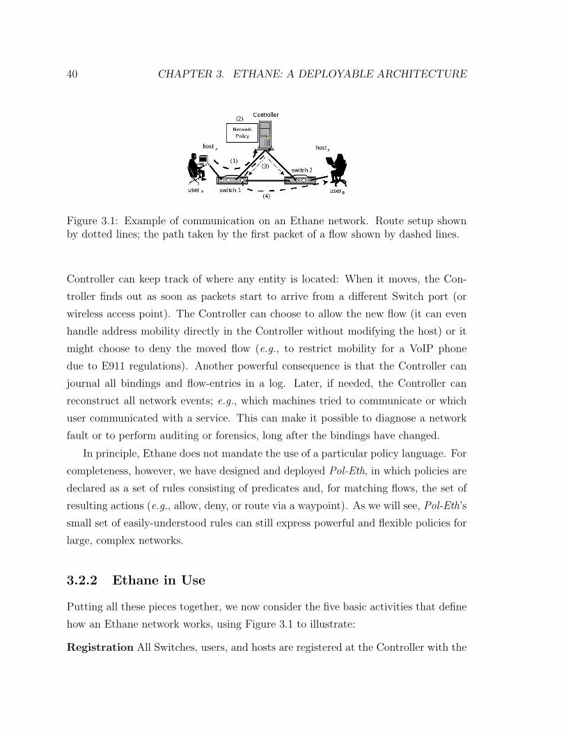
40 CHAPTER 3. ETHANE: A DEPLOYABLE ARCHITECTURE
Figure 3.1: Example of communication on an Ethane network. Route setup shownby dotted lines; the path taken by the first packet of a flow shown by dashed lines.
Controller can keep track of where any entity is located: When it moves, the Con-
troller finds out as soon as packets start to arrive from a different Switch port (or
wireless access point). The Controller can choose to allow the new flow (it can even
handle address mobility directly in the Controller without modifying the host) or it
might choose to deny the moved flow (e.g., to restrict mobility for a VoIP phone
due to E911 regulations). Another powerful consequence is that the Controller can
journal all bindings and flow-entries in a log. Later, if needed, the Controller can
reconstruct all network events; e.g., which machines tried to communicate or which
user communicated with a service. This can make it possible to diagnose a network
fault or to perform auditing or forensics, long after the bindings have changed.
In principle, Ethane does not mandate the use of a particular policy language. For
completeness, however, we have designed and deployed Pol-Eth, in which policies are
declared as a set of rules consisting of predicates and, for matching flows, the set of
resulting actions (e.g., allow, deny, or route via a waypoint). As we will see, Pol-Eth’s
small set of easily-understood rules can still express powerful and flexible policies for
large, complex networks.
3.2.2 Ethane in Use
Putting all these pieces together, we now consider the five basic activities that define
how an Ethane network works, using Figure 3.1 to illustrate:
Registration All Switches, users, and hosts are registered at the Controller with the
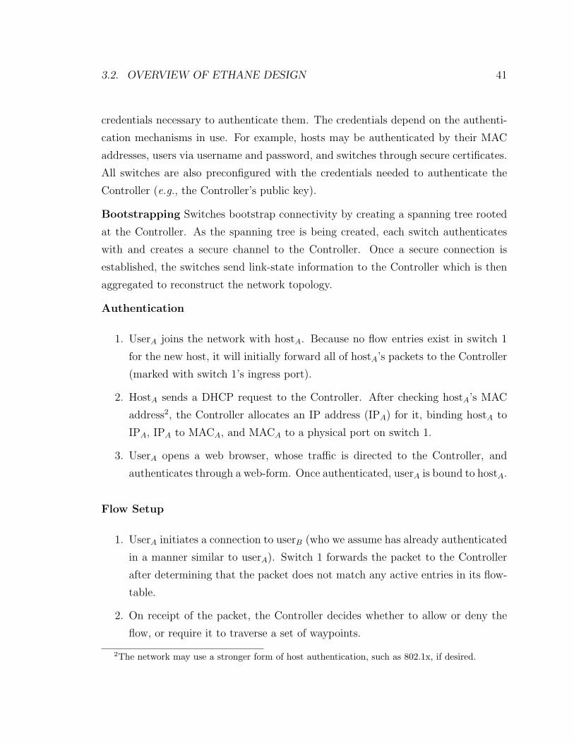
3.2. OVERVIEW OF ETHANE DESIGN 41
credentials necessary to authenticate them. The credentials depend on the authenti-
cation mechanisms in use. For example, hosts may be authenticated by their MAC
addresses, users via username and password, and switches through secure certificates.
All switches are also preconfigured with the credentials needed to authenticate the
Controller (e.g., the Controller’s public key).
Bootstrapping Switches bootstrap connectivity by creating a spanning tree rooted
at the Controller. As the spanning tree is being created, each switch authenticates
with and creates a secure channel to the Controller. Once a secure connection is
established, the switches send link-state information to the Controller which is then
aggregated to reconstruct the network topology.
Authentication
1. UserA joins the network with hostA. Because no flow entries exist in switch 1
for the new host, it will initially forward all of hostA’s packets to the Controller
(marked with switch 1’s ingress port).
2. HostA sends a DHCP request to the Controller. After checking hostA’s MAC
address2, the Controller allocates an IP address (IPA) for it, binding hostA to
IPA, IPA to MACA, and MACA to a physical port on switch 1.
3. UserA opens a web browser, whose traffic is directed to the Controller, and
authenticates through a web-form. Once authenticated, userA is bound to hostA.
Flow Setup
1. UserA initiates a connection to userB (who we assume has already authenticated
in a manner similar to userA). Switch 1 forwards the packet to the Controller
after determining that the packet does not match any active entries in its flow-
table.
2. On receipt of the packet, the Controller decides whether to allow or deny the
flow, or require it to traverse a set of waypoints.
2The network may use a stronger form of host authentication, such as 802.1x, if desired.
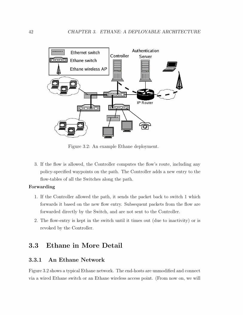
42 CHAPTER 3. ETHANE: A DEPLOYABLE ARCHITECTURE
Figure 3.2: An example Ethane deployment.
3. If the flow is allowed, the Controller computes the flow’s route, including any
policy-specified waypoints on the path. The Controller adds a new entry to the
flow-tables of all the Switches along the path.
Forwarding
1. If the Controller allowed the path, it sends the packet back to switch 1 which
forwards it based on the new flow entry. Subsequent packets from the flow are
forwarded directly by the Switch, and are not sent to the Controller.
2. The flow-entry is kept in the switch until it times out (due to inactivity) or is
revoked by the Controller.
3.3 Ethane in More Detail
3.3.1 An Ethane Network
Figure 3.2 shows a typical Ethane network. The end-hosts are unmodified and connect
via a wired Ethane switch or an Ethane wireless access point. (From now on, we will
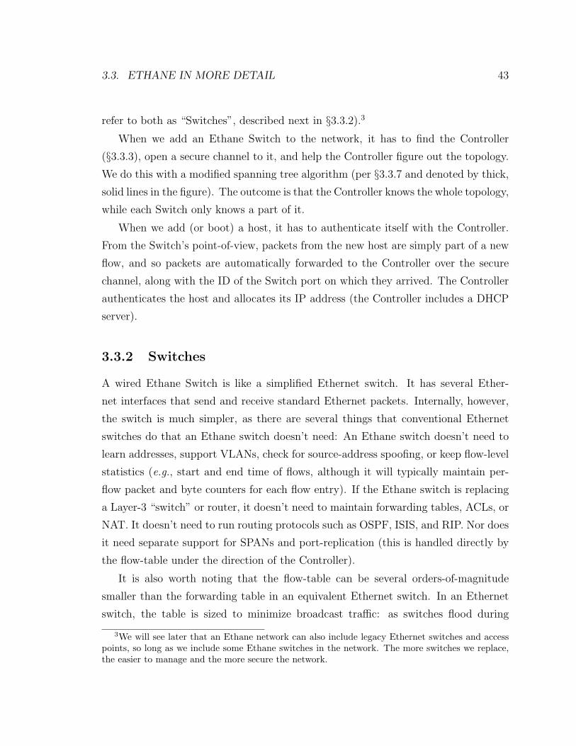
3.3. ETHANE IN MORE DETAIL 43
refer to both as “Switches”, described next in §3.3.2).3
When we add an Ethane Switch to the network, it has to find the Controller
(§3.3.3), open a secure channel to it, and help the Controller figure out the topology.
We do this with a modified spanning tree algorithm (per §3.3.7 and denoted by thick,
solid lines in the figure). The outcome is that the Controller knows the whole topology,
while each Switch only knows a part of it.
When we add (or boot) a host, it has to authenticate itself with the Controller.
From the Switch’s point-of-view, packets from the new host are simply part of a new
flow, and so packets are automatically forwarded to the Controller over the secure
channel, along with the ID of the Switch port on which they arrived. The Controller
authenticates the host and allocates its IP address (the Controller includes a DHCP
server).
3.3.2 Switches
A wired Ethane Switch is like a simplified Ethernet switch. It has several Ether-
net interfaces that send and receive standard Ethernet packets. Internally, however,
the switch is much simpler, as there are several things that conventional Ethernet
switches do that an Ethane switch doesn’t need: An Ethane switch doesn’t need to
learn addresses, support VLANs, check for source-address spoofing, or keep flow-level
statistics (e.g., start and end time of flows, although it will typically maintain per-
flow packet and byte counters for each flow entry). If the Ethane switch is replacing
a Layer-3 “switch” or router, it doesn’t need to maintain forwarding tables, ACLs, or
NAT. It doesn’t need to run routing protocols such as OSPF, ISIS, and RIP. Nor does
it need separate support for SPANs and port-replication (this is handled directly by
the flow-table under the direction of the Controller).
It is also worth noting that the flow-table can be several orders-of-magnitude
smaller than the forwarding table in an equivalent Ethernet switch. In an Ethernet
switch, the table is sized to minimize broadcast traffic: as switches flood during
3We will see later that an Ethane network can also include legacy Ethernet switches and accesspoints, so long as we include some Ethane switches in the network. The more switches we replace,the easier to manage and the more secure the network.
44 CHAPTER 3. ETHANE: A DEPLOYABLE ARCHITECTURE
learning, this can swamp links and makes the network less secure.4 As a result, an
Ethernet switch needs to remember all the addresses it’s likely to encounter; even
small wiring closet switches typically contain a million entries. Ethane switches, on
the other hand, can have much smaller flow-tables: they only need to keep track of
flows in-progress. For a wiring closet, this is likely to be a few hundred entries at
a time, small enough to be held in a tiny fraction of a switching chip. Even for a
campus-level switch, where perhaps tens of thousands of flows could be ongoing, it
can still use on-chip memory that saves cost and power.
In summary, we can expect an Ethane switch to be far simpler than its corre-
sponding Ethernet switch, without any loss of functionality. In fact, we expect that
a large box of power-hungry and expensive equipment will be replaced by a handful
of chips on a board.
Flow Table and Flow Entries The Switch datapath is a managed flow table.
Flow entries contain a Header (to match packets against), an Action (to tell the
switch what to do with the packet), and Per-Flow Data (which we describe below).
There are two common types of entry in the flow-table: per-flow entries describing
application flows that should be forwarded, and per-host entries that describe misbe-
having hosts whose packets should be dropped. For TCP/UDP flows, the Header field
covers the TCP/UDP, IP, and Ethernet headers, as well as physical port informa-
tion. The associated Action is to forward the packet to a particular interface, update
a packet-and-byte counter (in the Per-Flow Data), and set an activity bit (so that
inactive entries can be timed-out). For misbehaving hosts, the Header field contains
an Ethernet source address and the physical ingress port5. The associated Action is
to drop the packet, update a packet-and-byte counter, and set an activity bit (to tell
when the host has stopped sending).
Only the Controller can add entries to the flow table. Entries are removed because
they timeout due to inactivity (local decision) or because they are revoked by the
Controller. The Controller might revoke a single, badly behaved flow, or it might
4In fact, network administrators often use manually configured and inflexible VLANs to reduceflooding.
5If a host is spoofing, its first-hop port can be shut of directly (§3.3.3).
3.3. ETHANE IN MORE DETAIL 45
remove a whole group of flows belonging to a misbehaving host, a host that has just
left the network, or a host whose privileges have just changed.
The flow-table is implemented using two exact-match tables: One for application
flow entries and one for misbehaving host entries. Because flow entries are exact
matches, rather than longest-prefix matches, it is easy to use hashing schemes in
conventional memories rather than expensive, power-hungry TCAMs.
Other Actions are possible in addition to just forward and drop. For example, a
Switch might maintain multiple queues for different classes of traffic, and the Con-
troller can tell it to queue packets from application flows in a particular queue by
inserting queue IDs into the flow table. This can be used for end-to-end L2 isolation
for classes of users or hosts. A Switch could also perform address translation by re-
placing packet headers. This could be used to obfuscate addresses in the network by
“swapping” addresses at each Switch along the path—an eavesdropper would not be
able to tell which end-hosts are communicating—or to implement address translation
for NAT in order to conserve addresses. Finally, a Switch could control the rate of a
flow.
The Switch also maintains a handful of implementation-specific entries to reduce
the amount of traffic sent to the Controller. This number should remain small to
keep the Switch simple, although this is at the discretion of the designer. On one
hand, such entries can reduce the amount of traffic sent to the Controller; on the
other hand, any traffic that misses on the flow-table will be sent to the Controller
anyway, so this is just an optimization.
It is worth pointing out that the secure channel from a Switch to its Controller
may pass through other Switches. As far as the other Switches are concerned, the
channel simply appears as an additional flow-entry in their table.
Local Switch Manager The Switch needs a small local manager to establish and
maintain the secure channel to the Controller, to monitor link status, and to provide
an interface for any additional Switch-specific management and diagnostics. (We
implemented our manager in the switch’s software layer.)
There are two ways a Switch can talk to the Controller. The first one, which we
46 CHAPTER 3. ETHANE: A DEPLOYABLE ARCHITECTURE
have assumed so far, is for Switches that are part of the same physical network as
the Controller. We expect this to be the most common case; e.g., in an enterprise
network on a single campus. In this case, the Switch finds the Controller using our
modified Minimum Spanning Tree protocol described in §3.3.7. The process results
in a secure channel from Switch to Switch all the way to the Controller.
If the Switch is not within the same broadcast domain as the Controller, the
Switch can create an IP tunnel to it (after being manually configured with its IP
address). This approach can be used to control Switches in arbitrary locations, e.g.,
the other side of a conventional router or in a remote location. In one interesting
application of Ethane, the Switch (most likely a wireless access point) is placed in a
home or small business, managed remotely by the Controller over this secure tunnel.
The local Switch manager relays link status to the Controller so it can reconstruct
the topology for route computation. Switches maintain a list of neighboring switches
by broadcasting and receiving neighbor-discovery messages. Neighbor lists are sent
to the Controller after authentication, on any detectable change in link status, and
periodically every 15 seconds.
3.3.3 Controller
The Controller is the brain of the network and has many tasks; Figure 3.3 gives a
block-diagram. The components do not have to be co-located on the same machine
(they are not in our implementation).
Briefly, the components work as follows. The authentication system is passed
all traffic from unauthenticated or unbound MAC addresses. It authenticates users
and hosts using credentials stored in the registration database. Once a host or user
authenticates, the Controller remembers to which switch port they are connected.
The Controller holds the policy rules which are compiled into a fast lookup table
(see §3.4). When a new flow starts, it is checked against the rules to see if it should
be accepted, denied, or routed through a waypoint. Next, the route computation uses
the network topology to pick the flow’s route. The topology is maintained by the
switch manager, which receives link updates from the Switches.
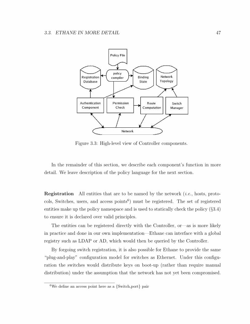
3.3. ETHANE IN MORE DETAIL 47
Figure 3.3: High-level view of Controller components.
In the remainder of this section, we describe each component’s function in more
detail. We leave description of the policy language for the next section.
Registration All entities that are to be named by the network (i.e., hosts, proto-
cols, Switches, users, and access points6) must be registered. The set of registered
entities make up the policy namespace and is used to statically check the policy (§3.4)
to ensure it is declared over valid principles.
The entities can be registered directly with the Controller, or—as is more likely
in practice and done in our own implementation—Ethane can interface with a global
registry such as LDAP or AD, which would then be queried by the Controller.
By forgoing switch registration, it is also possible for Ethane to provide the same
“plug-and-play” configuration model for switches as Ethernet. Under this configu-
ration the switches would distribute keys on boot-up (rather than require manual
distribution) under the assumption that the network has not yet been compromised.
6We define an access point here as a {Switch,port} pair

48 CHAPTER 3. ETHANE: A DEPLOYABLE ARCHITECTURE
Authentication All Switches, hosts, and users must authenticate with the network.
Ethane does not specify a particular host authentication mechanism; a network could
support multiple authentication methods (e.g., 802.1x or explicit user login) and
employ entity-specific authentication methods. In our implementation, for example,
hosts authenticate by presenting registered MAC addresses7, while users authenticate
through a web front-end to a Kerberos server. Switches authenticate using SSL with
server- and client-side certificates.
Tracking Bindings One of Ethane’s most powerful features is that it can easily
track all the bindings between names, addresses, and physical ports on the network,
even as switches, hosts, and users join, leave, and move around the network. It
is Ethane’s ability to track these dynamic bindings that makes the policy language
possible—-it allows us to describe policies in terms of users and hosts, yet implement
the policy using flow-tables in Switches.
A binding is never made without requiring authentication, so as to prevent an
attacker assuming the identity of another host or user. When the Controller detects
that a user or host leaves, all of its bindings are invalidated, and all of its flows are
revoked at the Switch to which it was connected. Unfortunately, in some cases, we
cannot get reliable explicit join and leave events from the network. Therefore, the
Controller may resort to timeouts or the detection of movement to another physical
access point before revoking access.
Namespace Interface Because Ethane tracks all the bindings between users, hosts,
and addresses, it can make information available to network managers, auditors, or
anyone else who seeks to understand who sent what packet and when.
In current networks, while it is possible to collect packet traces, it is almost impos-
sible to figure out later which user—or even which host—sent or received the packets,
as the addresses are dynamic and there is no known relationship between users and
packet addresses.
An Ethane Controller can journal all the authentication and binding information:
7We acknowledge that this is a weak form of authentication and plan to replace it with 802.1x.
3.3. ETHANE IN MORE DETAIL 49
The machine a user is logged in to, the Switch port their machine is connected to,
the MAC address of their packets, and so on. Armed with a packet trace and such a
journal, it is possible to determine exactly which user sent a packet, when it was sent,
the path it took, and its destination. Obviously, this information is very valuable for
both fault diagnosis and identifying break-ins. On the other hand, the information
is sensitive and controls need to be placed on who can access it. We expect Ethane
Controllers to provide an interface that gives privileged users access to the informa-
tion. In our own system, we built a modified DNS server that accepts a query with
a timestamp, and returns the complete bound namespace associated with a specified
user, host, or IP address (described in §3.5).
Permission Checks and State Upon receiving a packet, the Controller checks
the policy to see if the flow is allowed. Section 3.4 describes our policy model and
implementation.
The Controller can be implemented to be stateful or stateless. A stateful Controller
keeps track of all the flows it has created. When the policy changes, when the topology
changes, or when a host or user misbehaves, a stateful Controller can traverse its list
of flows and make changes where necessary. A stateless Controller does not keep track
of the flows it created; it relies on the Switches to keep track of their flow-tables. If
anything changes or moves, the associated flows would be revoked by the Controller
sending commands to the Switch’s Local Manager.
We leave it as a design choice as to whether a Controller is stateful or stateless, be-
lieving there are arguments for and against both approaches. In our implementation,
we built a stateless Controller to determine its feasibility.
Enforcing Resource Limits There are many occasions when a Controller wants
to limit the resources granted to a user, host, or flow. For example, it might wish to
limit a flow’s rate, limit the rate at which new flows are setup, or limit the number
of IP addresses allocated. The limits will depend on the design of the Controller and
the Switch, and they will be at the discretion of the network manager. In general,
however, Ethane makes it easy to enforce these limits either by installing a filter in a
50 CHAPTER 3. ETHANE: A DEPLOYABLE ARCHITECTURE
Switch’s flow-table or by telling the Switch to limit a flow’s rate.
The ability to directly manage resources from the Controller is the primary means
of protecting the network from resource exhaustion attacks. To protect itself from
connection flooding from unauthenticated hosts, a Controller can place a limit on
the number of authentication requests per host and per switch port; hosts that ex-
ceed their allocation can be closed down by adding an entry in the flow-table that
blocks their Ethernet address. If such hosts spoof their address, the Controller can
disable the Switch port. A similar approach can be used to prevent flooding from
authenticated hosts.
Flow state exhaustion attacks are also preventable through resource limits. Since
each flow setup request is attributable to a user, host or access point, the controller
can enforce limits on the number of outstanding flows per identifiable source. The
network may also support a more advanced flow allocation policies, such as enforcing
strict limits on the number of flows forwarded in hardware per source, and looser
limits on the number of flows in the slower (and more abundant) software forwarding
tables.
3.3.4 Handling Broadcast and Multicast
Enterprise networks typically carry a lot of multicast and broadcast traffic—indeed,
VLANs were first introduced to limit overwhelming amounts of broadcast traffic. It
is worth distinguishing broadcast traffic (which is mostly discovery protocols, such as
ARP) from multicast traffic (which is often from useful applications, such as video).
In a flow-based network like Ethane, it is quite easy for Switches to handle mul-
ticast: The Switch keeps a bitmap for each flow to indicate which ports the packets
are to be sent to along the path.
In principle, broadcast discovery protocols are also easy to handle in the Con-
troller. Typically, a host is trying to find a server or an address; given that the
Controller knows all, it can reply to a request without creating a new flow and
broadcasting the traffic. This provides an easy solution for ARP traffic (which is
3.3. ETHANE IN MORE DETAIL 51
a significant fraction of all network traffic): The Controller knows all IP and Eth-
ernet addresses and can reply directly. In practice, however, ARP could generate a
huge load for the Controller; one design choice would be to provide a dedicated ARP
server in the network to which that all Switches direct all ARP traffic. But there is
a dilemma when trying to support other discovery protocols; each one has its own
protocol, and it would be onerous for the Controller to understand all of them. Our
own approach has been to implement the common ones directly in the Controller, and
then broadcast low-level requests with a rate-limit. Clearly this approach does not
scale well, and we hope that, if Ethane becomes widespread in the future, discovery
protocols will largely go away. After all, they are just looking for binding information
that the network already knows; it should be possible to provide a direct way to query
the network. We discuss this problem further in §3.7.
3.3.5 Replicating the Controller for Fault-Tolerance and Scal-
ability
Designing a network architecture around a central controller raises concerns about
availability and scalability. While our measurements in §3.6 suggest that thousands
of machines can be managed by a single desktop computer, multiple Controllers may
be desirable to provide fault-tolerance or to scale to very large networks.
This section describes three techniques for replicating the Controller. In the sim-
plest two approaches, which focus solely on improving fault-tolerance, secondary Con-
trollers are ready to step in upon the primary’s failure: these can be in cold-standby
(having no network binding state) or warm-standby (having network binding state)
modes. In the fully-replicated model, which also improves scalability, requests from
Switches are spread over multiple active Controllers.
In the cold-standby approach, a primary Controller is the root of the modi-
fied spanning tree (MST) and handles all registration, authentication, and flow-
establishment requests. Backup Controllers sit idly-by waiting to take over if needed.
All Controllers participate in the MST, sending HELLO messages to Switches adver-
tising their ID. Just as with a standard spanning tree, if the root with the “lowest”
52 CHAPTER 3. ETHANE: A DEPLOYABLE ARCHITECTURE
ID fails, the network will converge on a new root (i.e., a new Controller). If a backup
becomes the new MST root, they will start to receive flow requests and begin acting
as the primary Controller. In this way, Controllers can be largely unaware of each
other: the backups need only contain the registration state and the network policy (as
this data changes very slowly, simple consistency methods can be used). The main
advantage of cold-standby is its simplicity; the downside is that hosts, Switches, and
users need to re-authenticate and re-bind upon primary failure. Furthermore, in large
networks, it might take a while for the MST to reconverge.
The warm-standby approach is more complex, but recovers faster. In this ap-
proach, a separate MST is created for every Controller. The Controllers monitor one
another’s liveness and, upon detecting the primary’s failure, a secondary Controller
takes over based on a static ordering. As before, slowly-changing registration and
network policy are kept consistent among the controllers, but we now need to repli-
cate bindings across Controllers as well. Because these bindings can change quickly
as new users and hosts come and go, we recommend that only weak consistency be
maintained: Because Controllers make bind events atomic, primary failures can at
worst lose the latest bindings, requiring that some new users and hosts reauthenticate
themselves.
The fully-replicated approach takes this one step further and has two or more
active Controllers. While an MST is again constructed for each Controller, a Switch
need only authenticate itself to one Controller and can then spread its flow-requests
over the Controllers (e.g., by hashing or round-robin). With such replication, we
should not underestimate the job of maintaining consistent journals of the bind
events. We expect that most implementations will simply use gossiping to provide a
weakly-consistent ordering over events. Pragmatic techniques can avoid many poten-
tial problems that would otherwise arise, e.g., having Controllers use different private
IP address spaces during DHCP allocation to prevent temporary IP allocation con-
flicts. Of course, there are well-known, albeit heavier-weight, alternatives to provide
stronger consistency guarantees if desired (e.g., replicated state machines). There is
plenty of scope for further study: Now that Ethane provides a platform with which
to capture and manage all bindings, we expect future improvements can make the
3.3. ETHANE IN MORE DETAIL 53
system more robust.
3.3.6 Link Failures
Link and Switch failures must not bring down the network as well. Recall that
Switches always send neighbor-discovery messages to keep track of link-state. When
a link fails, the Switch removes all flow-table entries tied to the failed port and sends
its new link-state information to the Controller. This way, the Controller also learns
the new topology. When packets arrive for a removed flow-entry at the Switch, the
packets are sent to the Controller—much like they are new flows—and the Controller
computes and installs a new path based on the new topology.
3.3.7 Bootstrapping
When the network starts, the Switches must connect and authenticate with the Con-
troller.8 Ethane bootstraps in a similar way to [29]. On startup, the network creates a
minimum spanning tree with the Controller advertising itself as the root. Each switch
has been configured with credentials for the Controller and the Controller with the
credentials for all the switches.
If a switch finds a shorter path to the Controller, it attempts two way authenti-
cation with it before advertising that path as a valid route. Therefore the minimum
spanning tree grows radially from the Controller, hop-by-hop as each Switch authen-
ticates.
Authentication is done using the preconfigured credentials to ensure that a misbe-
having node cannot masquerade as the Controller or another Switch. If authentication
is successful, the switch creates an encrypted connection with the Controller which is
used for all communication between the pair.
By design, the Controller knows the upstream Switch and physical port to which
each authenticating Switch is attached. After a Switch authenticates and establishes
a secure channel to the Controller, it forwards all packets it receives for which it does
8This method does not apply to Switches that use an IP tunnel to connect to the Controller—theysimply send packets via the tunnel and then authenticate.
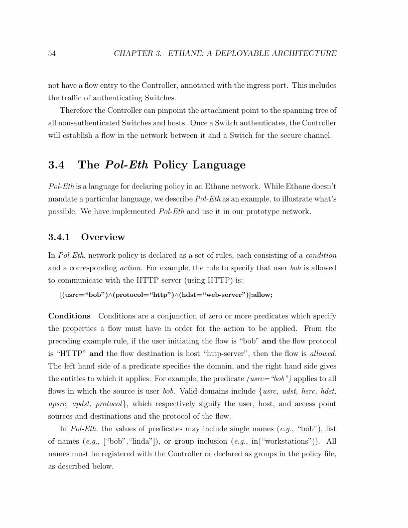
54 CHAPTER 3. ETHANE: A DEPLOYABLE ARCHITECTURE
not have a flow entry to the Controller, annotated with the ingress port. This includes
the traffic of authenticating Switches.
Therefore the Controller can pinpoint the attachment point to the spanning tree of
all non-authenticated Switches and hosts. Once a Switch authenticates, the Controller
will establish a flow in the network between it and a Switch for the secure channel.
3.4 The Pol-Eth Policy Language
Pol-Eth is a language for declaring policy in an Ethane network. While Ethane doesn’t
mandate a particular language, we describe Pol-Eth as an example, to illustrate what’s
possible. We have implemented Pol-Eth and use it in our prototype network.
3.4.1 Overview
In Pol-Eth, network policy is declared as a set of rules, each consisting of a condition
and a corresponding action. For example, the rule to specify that user bob is allowed
to communicate with the HTTP server (using HTTP) is:
[(usrc=“bob”)∧(protocol=“http”)∧(hdst=“web-server”)]:allow;
Conditions Conditions are a conjunction of zero or more predicates which specify
the properties a flow must have in order for the action to be applied. From the
preceding example rule, if the user initiating the flow is “bob” and the flow protocol
is “HTTP” and the flow destination is host “http-server”, then the flow is allowed.
The left hand side of a predicate specifies the domain, and the right hand side gives
the entities to which it applies. For example, the predicate (usrc=“bob”) applies to all
flows in which the source is user bob. Valid domains include {usrc, udst, hsrc, hdst,
apsrc, apdst, protocol}, which respectively signify the user, host, and access point
sources and destinations and the protocol of the flow.
In Pol-Eth, the values of predicates may include single names (e.g., “bob”), list
of names (e.g., [“bob”,“linda”]), or group inclusion (e.g., in(“workstations”)). All
names must be registered with the Controller or declared as groups in the policy file,
as described below.
3.4. THE POL-ETH POLICY LANGUAGE 55
Actions Actions include allow, deny, waypoints, and outbound-only (for NAT-like
security). Waypoint declarations include a list of entities to route the flow through,
e.g., waypoints(“ids”,“http-proxy”).
3.4.2 Rule and Action Precedence
Pol-Eth rules are independent and don’t contain an intrinsic ordering; thus, multiple
rules with conflicting actions may be satisfied by the same flow. Conflicst are resolved
by assigning priorities based on declaration order. If one rule precedes another in the
policy file, it is assigned a higher priority.
As an example, in the following declaration, bob may accept incoming connections
even if he is a student.# bob is unrestricted
[(udst=‘‘bob’’)]:allow;
# all students can make outbound connections
[(usrc=in(‘‘students’’))]:outbound-only;
# deny everything by default (most general)
[] : deny ;
Unfortunately, in today’s multi-user operating systems, it is difficult from a net-
work perspective to attribute outgoing traffic to a particular user.9 In Ethane, if
multiple-users are logged into the same machine (and not identifiable from within the
network), Ethane applies the least restrictive action to each of the flows. This is an
obvious relaxation of the security policy. To address this, we are exploring integration
with trusted end-host operating systems to provide user-isolation and identification
(for example, by providing each user with a virtual machine having a unique MAC).
3.4.3 Supporting Arbitrary Expressions
Pol-Eth also allows predicates to contain arbitrary functions. For example, the pred-
icate (expr=“foo”) will execute the function “foo” at runtime and use the boolean
return value as the outcome. Predicate functions are written in C++ and executed
9Existing mechanisms to provide such transparency, such as identd, are notoriously insecure
56 CHAPTER 3. ETHANE: A DEPLOYABLE ARCHITECTURE
within the Ethane namespace. During execution, they have access to all parameters
of the flow as well as to the full binding state of the network.
The inclusion of arbitrary functions with the expressibility of a general program-
ming language allows predicates to maintain local state, affect system state, or access
system libraries. For example, we have created predicates that depend on the time-
of-day and contain dependencies on which users or hosts are logged onto the network.
A notable downside is that it becomes impossible to statically reason about safety
and execution times: a poorly written function can crash the Controller or slow down
permission checks.
3.4.4 Policy Example
Figure 3.4 contains a derivative of the policy which governs connectivity for our
university deployment. Pol-Eth policy files consist of three parts—group declarations,
expressions, and rules—each separated by a ’%%’ delimiter.
In this policy, all flows are permitted by the first (and most general) rule; we
consider this default-on. Servers are not allowed to make connections to the rest of
the network, providing protection similar to DMZs today. Phones and computers
can never communicate. Laptops are protected from inbound flows (similar to the
protection provided by NAT), while workstations can communicate with each other.
Guest users from wireless access points may only use HTTP and must go through a
web proxy, while authenticated users have no such restrictions.
3.4.5 Implementation
Given how frequently new flows are created - and how fast decisions must be made
- it is not practical to interpret the network policy. Instead, we need to compile it.
But compiling Pol-Eth is non-trivial because of the potentially huge namespace in the
network: Creating a lookup table for all possible flows specified in the policy would
be impractical.
Our Pol-Eth implementation combines compilation and just-in-time creation of
search functions. Each rule is associated with the principles to which it applies. This
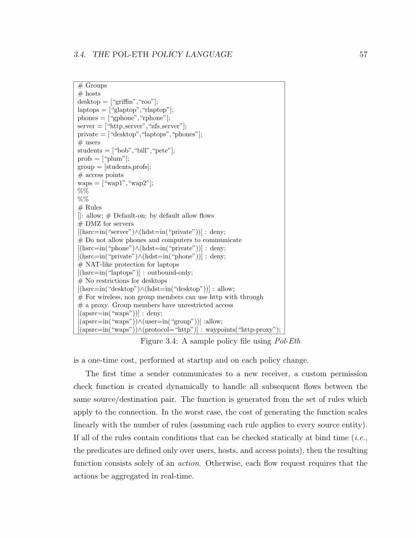
3.4. THE POL-ETH POLICY LANGUAGE 57
# Groups# hostsdesktop = [“griffin”,“roo”];laptops = [“glaptop”,“rlaptop”];phones = [“gphone”,“rphone”];server = [“http server”,“nfs server”];private = [“desktop”,“laptops”,“phones”];# usersstudents = [“bob”,“bill”,“pete”];profs = [“plum”];group = [students,profs];# access pointswaps = [“wap1”,“wap2”];%%%%# Rules[]: allow; # Default-on: by default allow flows# DMZ for servers[(hsrc=in(“server”)∧(hdst=in(“private”))] : deny;# Do not allow phones and computers to communicate[(hsrc=in(“phone”)∧(hdst=in(“private”))] : deny;[(hsrc=in(“private”)∧(hdst=in(“phone”))] : deny;# NAT-like protection for laptops[(hsrc=in(“laptops”)] : outbound-only;# No restrictions for desktops[(hsrc=in(“desktop”)∧(hdst=in(“desktop”))] : allow;# For wireless, non group members can use http with through# a proxy. Group members have unrestricted access[(apsrc=in(“waps”))] : deny;[(apsrc=in(“waps”))∧(user=in(“group”))] :allow;[(apsrc=in(“waps”))∧(protocol=“http”)] : waypoints(“http-proxy”);
Figure 3.4: A sample policy file using Pol-Eth
is a one-time cost, performed at startup and on each policy change.
The first time a sender communicates to a new receiver, a custom permission
check function is created dynamically to handle all subsequent flows between the
same source/destination pair. The function is generated from the set of rules which
apply to the connection. In the worst case, the cost of generating the function scales
linearly with the number of rules (assuming each rule applies to every source entity).
If all of the rules contain conditions that can be checked statically at bind time (i.e.,
the predicates are defined only over users, hosts, and access points), then the resulting
function consists solely of an action. Otherwise, each flow request requires that the
actions be aggregated in real-time.
58 CHAPTER 3. ETHANE: A DEPLOYABLE ARCHITECTURE
We have implemented a source-to-source compiler that generates C++ from a
Pol-Eth policy file. The resulting source is then compiled and linked into the Ethane
binary. As a consequence, policy changes currently require relinking the Controller.
We are currently upgrading the policy compiler so that policy changes can be dynam-
ically loaded at runtime.
3.5 Prototype and Deployment
We’ve built and deployed a functional Ethane network at our university over the
last four months. At the time of writing, Ethane connects over 300 registered hosts,
and several hundred users. Our deployment includes 19 Switches of three different
types: Ethane wireless access points, Ethane Ethernet switches (in two flavors: one
gigabit in dedicated hardware, and one in software). Registered hosts include laptops,
printers, VoIP phones, desktop workstations and servers. We have also deployed a
remote Switch in a private residence. The Switch tunnels to
We’ve learned a lot by deploying and managing an Ethane network - and many
of these lessons have improved our design and our understanding of how network
policies can be used. In the following section we describe our deployment at a large
university, and try to draw some lessons and conclusions based on our experience.
3.5.1 Switches
We have built three different Ethane Switches: An 802.11g wireless access point
(based on a commercial access point), a wired 4-port Gigabit Ethernet Switch that
forwards packets at line-speed (based on the NetFPGA programmable switch plat-
form [62], and written in Verilog), and a wired 4-port Ethernet Switch in Linux on
a desktop-PC (in software, as a development environment and to allow rapid deploy-
ment and evolution).
For design re-use, we implemented the same flow-table in each Switch design
(even though in real-life we would optimize for each platform). The main table -
for packets that should be forwarded (see Section 3.3.2) - has 8k flow entries and is
3.5. PROTOTYPE AND DEPLOYMENT 59
searched using an exact match on the whole header. We use two hash functions (two
CRCs) to reduce the chance of collisions, and we place only one flow in each entry
of the table. We chose 8k entries because of the limitations of the programmable
hardware (NetFPGA). A commercial ASIC-based hardware Switch, an NPU-based
Switch, or a software-only Switch would support many more entries. We implemented
the second table to hold dropped packets which also uses exact-match hashing.
In our implementation, we decided to make the dropped table much bigger (32k
entries). We did this because our Controller is stateless and we wanted to implement
the outbound-only action in the flow-table. When an outbound flow starts, we’d like
to setup the return-route at the same time - because the Controller is stateless, it
doesn’t remember that the outbound-flow was allowed. Unfortunately, when proxy
ARP is used, we don’t know the Ethernet address of packets flowing in the reverse
direction - we don’t know until they arrive. So, we use the second table to hold flow-
entries for return-routes (with a wildcard Ethernet address) as well as for dropped
packets. A stateful Controller wouldn’t need these entries.
Finally, we keep a small table for flows with wildcards in any field. These are
there for convenience during prototyping, while we determine how many entries a
real deployment need. It holds flow entries for the spanning tree messages, ARP and
DHCP.
Ethane Wireless Access Point Our access point runs on a Linksys WRTSL54GS
wireless router (266MHz MIPS, 32MB RAM) running OpenWRT [10]. The data-path
and flow-table is based on 5K lines of C++ (1.5K are for the flow-table). The local
switch manager is written in software and talks to the Controller using the native
Linux TCP stack. When running from within the kernel, the Ethane forwarding path
runs at 23Mb/s—the same speed as Linux IP forwarding and L2 bridging.
Ethane 4-port Gigabit Ethernet Switch: Hardware Solution The Switch is
implemented on NetFPGA v2.0 with four Gigabit Ethernet ports, a Xilinx Virtex-II
FPGA and 4Mbytes of SRAM for packet buffers and the flow-table. The hardware
forwarding path consists of 7k lines of Verilog; flow-entries are 40bytes long. Our
hardware can forward minimum size packets packets in full-duplex at line-rate of
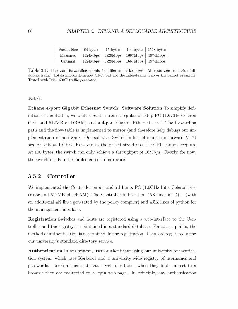
60 CHAPTER 3. ETHANE: A DEPLOYABLE ARCHITECTURE
Packet Size 64 bytes 65 bytes 100 bytes 1518 bytesMeasured 1524Mbps 1529Mbps 1667Mbps 1974MbpsOptimal 1524Mbps 1529Mbps 1667Mbps 1974Mbps
Table 3.1: Hardware forwarding speeds for different packet sizes. All tests were run with full-duplex traffic. Totals include Ethernet CRC, but not the Inter-Frame Gap or the packet preamble.Tested with Ixia 1600T traffic generator.
1Gb/s.
Ethane 4-port Gigabit Ethernet Switch: Software Solution To simplify defi-
nition of the Switch, we built a Switch from a regular desktop-PC (1.6GHz Celeron
CPU and 512MB of DRAM) and a 4-port Gigabit Ethernet card. The forwarding
path and the flow-table is implemented to mirror (and therefore help debug) our im-
plementation in hardware. Our software Switch in kernel mode can forward MTU
size packets at 1 Gb/s. However, as the packet size drops, the CPU cannot keep up.
At 100 bytes, the switch can only achieve a throughput of 16Mb/s. Clearly, for now,
the switch needs to be implemented in hardware.
3.5.2 Controller
We implemented the Controller on a standard Linux PC (1.6GHz Intel Celeron pro-
cessor and 512MB of DRAM). The Controller is based on 45K lines of C++ (with
an additional 4K lines generated by the policy compiler) and 4.5K lines of python for
the management interface.
Registration Switches and hosts are registered using a web-interface to the Con-
troller and the registry is maintained in a standard database. For access points, the
method of authentication is determined during registration. Users are registered using
our university’s standard directory service.
Authentication In our system, users authenticate using our university authentica-
tion system, which uses Kerberos and a university-wide registry of usernames and
passwords. Users authenticate via a web interface - when they first connect to a
browser they are redirected to a login web-page. In principle, any authentication
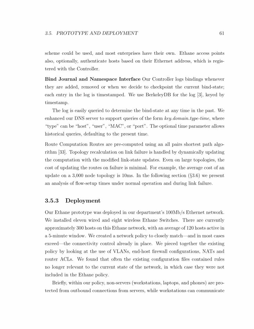
3.5. PROTOTYPE AND DEPLOYMENT 61
scheme could be used, and most enterprises have their own. Ethane access points
also, optionally, authenticate hosts based on their Ethernet address, which is regis-
tered with the Controller.
Bind Journal and Namespace Interface Our Controller logs bindings whenever
they are added, removed or when we decide to checkpoint the current bind-state;
each entry in the log is timestamped. We use BerkeleyDB for the log [3], keyed by
timestamp.
The log is easily queried to determine the bind-state at any time in the past. We
enhanced our DNS server to support queries of the form key.domain.type-time, where
“type” can be “host”, “user”, “MAC”, or “port”. The optional time parameter allows
historical queries, defaulting to the present time.
Route Computation Routes are pre-computed using an all pairs shortest path algo-
rithm [33]. Topology recalculation on link failure is handled by dynamically updating
the computation with the modified link-state updates. Even on large topologies, the
cost of updating the routes on failure is minimal. For example, the average cost of an
update on a 3,000 node topology is 10ms. In the following section (§3.6) we present
an analysis of flow-setup times under normal operation and during link failure.
3.5.3 Deployment
Our Ethane prototype was deployed in our department’s 100Mb/s Ethernet network.
We installed eleven wired and eight wireless Ethane Switches. There are currently
approximately 300 hosts on this Ethane network, with an average of 120 hosts active in
a 5-minute window. We created a network policy to closely match—and in most cases
exceed—the connectivity control already in place. We pieced together the existing
policy by looking at the use of VLANs, end-host firewall configurations, NATs and
router ACLs. We found that often the existing configuration files contained rules
no longer relevant to the current state of the network, in which case they were not
included in the Ethane policy.
Briefly, within our policy, non-servers (workstations, laptops, and phones) are pro-
tected from outbound connections from servers, while workstations can communicate
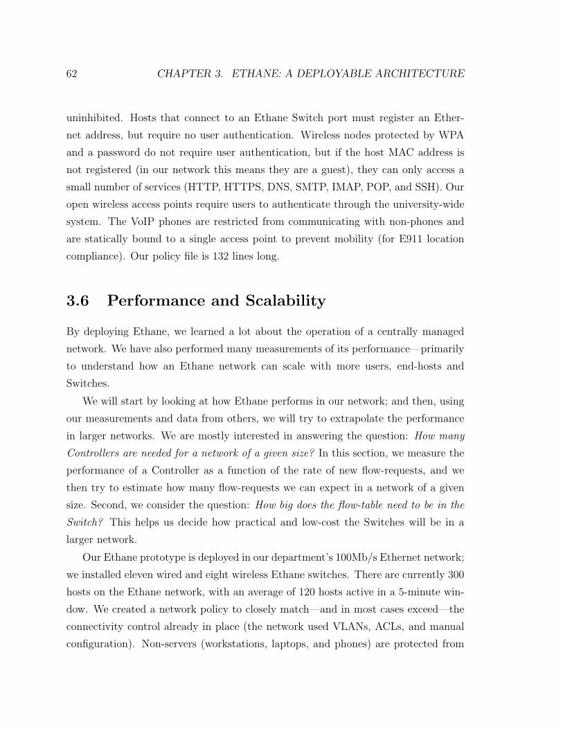
62 CHAPTER 3. ETHANE: A DEPLOYABLE ARCHITECTURE
uninhibited. Hosts that connect to an Ethane Switch port must register an Ether-
net address, but require no user authentication. Wireless nodes protected by WPA
and a password do not require user authentication, but if the host MAC address is
not registered (in our network this means they are a guest), they can only access a
small number of services (HTTP, HTTPS, DNS, SMTP, IMAP, POP, and SSH). Our
open wireless access points require users to authenticate through the university-wide
system. The VoIP phones are restricted from communicating with non-phones and
are statically bound to a single access point to prevent mobility (for E911 location
compliance). Our policy file is 132 lines long.
3.6 Performance and Scalability
By deploying Ethane, we learned a lot about the operation of a centrally managed
network. We have also performed many measurements of its performance—primarily
to understand how an Ethane network can scale with more users, end-hosts and
Switches.
We will start by looking at how Ethane performs in our network; and then, using
our measurements and data from others, we will try to extrapolate the performance
in larger networks. We are mostly interested in answering the question: How many
Controllers are needed for a network of a given size? In this section, we measure the
performance of a Controller as a function of the rate of new flow-requests, and we
then try to estimate how many flow-requests we can expect in a network of a given
size. Second, we consider the question: How big does the flow-table need to be in the
Switch? This helps us decide how practical and low-cost the Switches will be in a
larger network.
Our Ethane prototype is deployed in our department’s 100Mb/s Ethernet network;
we installed eleven wired and eight wireless Ethane switches. There are currently 300
hosts on the Ethane network, with an average of 120 hosts active in a 5-minute win-
dow. We created a network policy to closely match—and in most cases exceed—the
connectivity control already in place (the network used VLANs, ACLs, and manual
configuration). Non-servers (workstations, laptops, and phones) are protected from
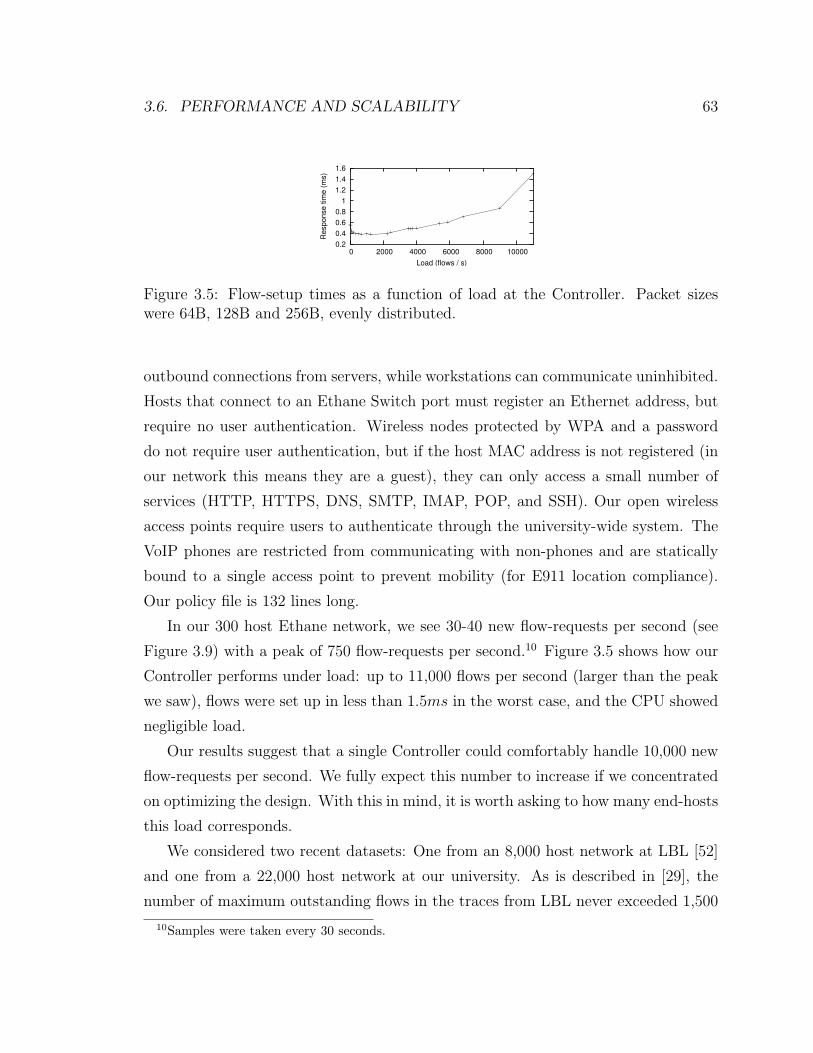
3.6. PERFORMANCE AND SCALABILITY 63
0.2 0.4 0.6 0.8
1 1.2 1.4 1.6
0 2000 4000 6000 8000 10000
Resp
onse
tim
e (m
s)
Load (flows / s)
Figure 3.5: Flow-setup times as a function of load at the Controller. Packet sizeswere 64B, 128B and 256B, evenly distributed.
outbound connections from servers, while workstations can communicate uninhibited.
Hosts that connect to an Ethane Switch port must register an Ethernet address, but
require no user authentication. Wireless nodes protected by WPA and a password
do not require user authentication, but if the host MAC address is not registered (in
our network this means they are a guest), they can only access a small number of
services (HTTP, HTTPS, DNS, SMTP, IMAP, POP, and SSH). Our open wireless
access points require users to authenticate through the university-wide system. The
VoIP phones are restricted from communicating with non-phones and are statically
bound to a single access point to prevent mobility (for E911 location compliance).
Our policy file is 132 lines long.
In our 300 host Ethane network, we see 30-40 new flow-requests per second (see
Figure 3.9) with a peak of 750 flow-requests per second.10 Figure 3.5 shows how our
Controller performs under load: up to 11,000 flows per second (larger than the peak
we saw), flows were set up in less than 1.5ms in the worst case, and the CPU showed
negligible load.
Our results suggest that a single Controller could comfortably handle 10,000 new
flow-requests per second. We fully expect this number to increase if we concentrated
on optimizing the design. With this in mind, it is worth asking to how many end-hosts
this load corresponds.
We considered two recent datasets: One from an 8,000 host network at LBL [52]
and one from a 22,000 host network at our university. As is described in [29], the
number of maximum outstanding flows in the traces from LBL never exceeded 1,500
10Samples were taken every 30 seconds.
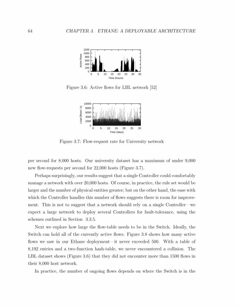
64 CHAPTER 3. ETHANE: A DEPLOYABLE ARCHITECTURE
0 200 400 600 800
1000 1200
0 5 10 15 20 25 30 35
Act
ive
flow
sTime (hours)
Figure 3.6: Active flows for LBL network [52]
0
2000
4000
6000
8000
10000
0 5 10 15 20 25 30
Load
(flo
ws
/ s)
Time (days)
Figure 3.7: Flow-request rate for University network
per second for 8,000 hosts. Our university dataset has a maximum of under 9,000
new flow-requests per second for 22,000 hosts (Figure 3.7).
Perhaps surprisingly, our results suggest that a single Controller could comfortably
manage a network with over 20,000 hosts. Of course, in practice, the rule set would be
larger and the number of physical entities greater; but on the other hand, the ease with
which the Controller handles this number of flows suggests there is room for improve-
ment. This is not to suggest that a network should rely on a single Controller—we
expect a large network to deploy several Controllers for fault-tolerance, using the
schemes outlined in Section 3.3.5.
Next we explore how large the flow-table needs to be in the Switch. Ideally, the
Switch can hold all of the currently active flows. Figure 3.8 shows how many active
flows we saw in our Ethane deployment—it never exceeded 500. With a table of
8,192 entries and a two-function hash-table, we never encountered a collision. The
LBL dataset shows (Figure 3.6) that they did not encounter more than 1500 flows in
their 8,000 host network.
In practice, the number of ongoing flows depends on where the Switch is in the
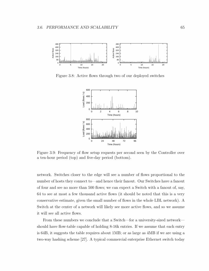
3.6. PERFORMANCE AND SCALABILITY 65
0
80
160
240
320
400
480
0 5 10 15 20
Act
ive
flow
s
Time (hours)
0
80
160
240
320
400
480
0 5 10 15 20
Act
ive
flow
s
Time (hours)
Figure 3.8: Active flows through two of our deployed switches
0
200
400
600
0 2 4 6 8 10
Load
(flo
ws
/ s)
Time (hours)
0
200
400
600
800
0 24 48 72 96
Load
(flo
ws
/ s)
Time (hours)
Figure 3.9: Frequency of flow setup requests per second seen by the Controller overa ten-hour period (top) and five-day period (bottom).
network. Switches closer to the edge will see a number of flows proportional to the
number of hosts they connect to—and hence their fanout. Our Switches have a fanout
of four and see no more than 500 flows; we can expect a Switch with a fanout of, say,
64 to see at most a few thousand active flows (it should be noted that this is a very
conservative estimate, given the small number of flows in the whole LBL network). A
Switch at the center of a network will likely see more active flows, and so we assume
it will see all active flows.
From these numbers we conclude that a Switch—for a university-sized network—
should have flow-table capable of holding 8-16k entries. If we assume that each entry
is 64B, it suggests the table requires about 1MB; or as large as 4MB if we are using a
two-way hashing scheme [27]. A typical commercial enterprise Ethernet switch today
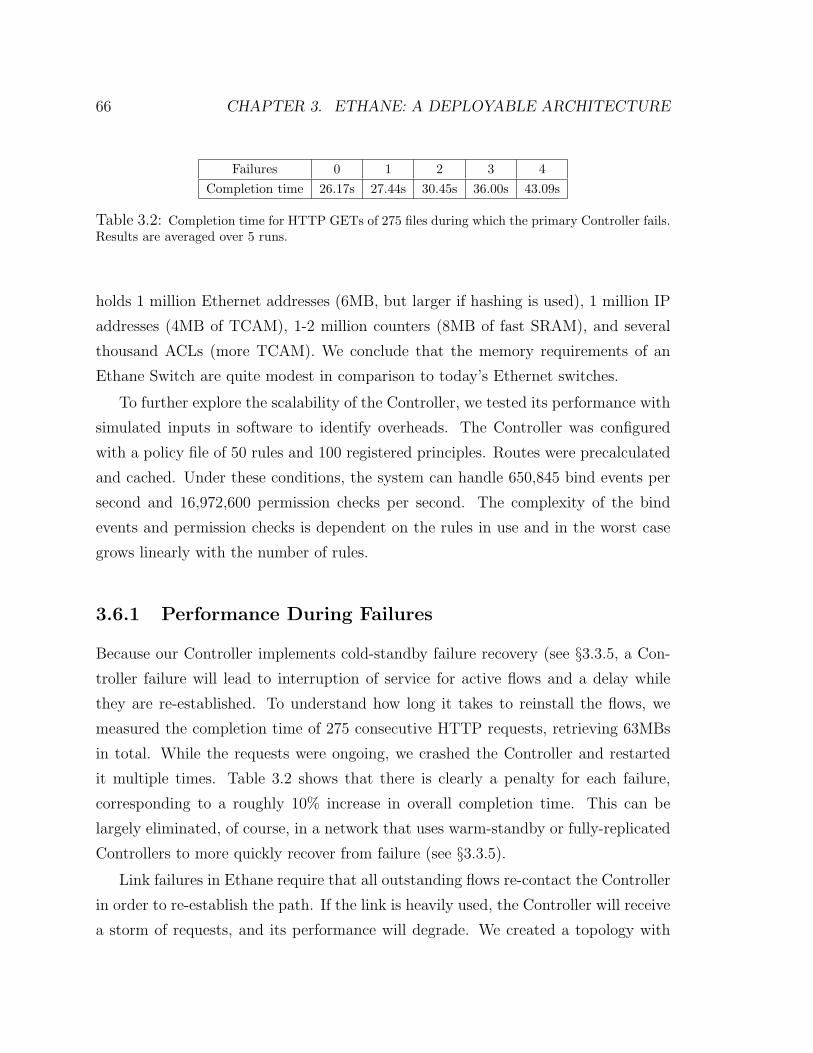
66 CHAPTER 3. ETHANE: A DEPLOYABLE ARCHITECTURE
Failures 0 1 2 3 4Completion time 26.17s 27.44s 30.45s 36.00s 43.09s
Table 3.2: Completion time for HTTP GETs of 275 files during which the primary Controller fails.Results are averaged over 5 runs.
holds 1 million Ethernet addresses (6MB, but larger if hashing is used), 1 million IP
addresses (4MB of TCAM), 1-2 million counters (8MB of fast SRAM), and several
thousand ACLs (more TCAM). We conclude that the memory requirements of an
Ethane Switch are quite modest in comparison to today’s Ethernet switches.
To further explore the scalability of the Controller, we tested its performance with
simulated inputs in software to identify overheads. The Controller was configured
with a policy file of 50 rules and 100 registered principles. Routes were precalculated
and cached. Under these conditions, the system can handle 650,845 bind events per
second and 16,972,600 permission checks per second. The complexity of the bind
events and permission checks is dependent on the rules in use and in the worst case
grows linearly with the number of rules.
3.6.1 Performance During Failures
Because our Controller implements cold-standby failure recovery (see §3.3.5, a Con-
troller failure will lead to interruption of service for active flows and a delay while
they are re-established. To understand how long it takes to reinstall the flows, we
measured the completion time of 275 consecutive HTTP requests, retrieving 63MBs
in total. While the requests were ongoing, we crashed the Controller and restarted
it multiple times. Table 3.2 shows that there is clearly a penalty for each failure,
corresponding to a roughly 10% increase in overall completion time. This can be
largely eliminated, of course, in a network that uses warm-standby or fully-replicated
Controllers to more quickly recover from failure (see §3.3.5).
Link failures in Ethane require that all outstanding flows re-contact the Controller
in order to re-establish the path. If the link is heavily used, the Controller will receive
a storm of requests, and its performance will degrade. We created a topology with
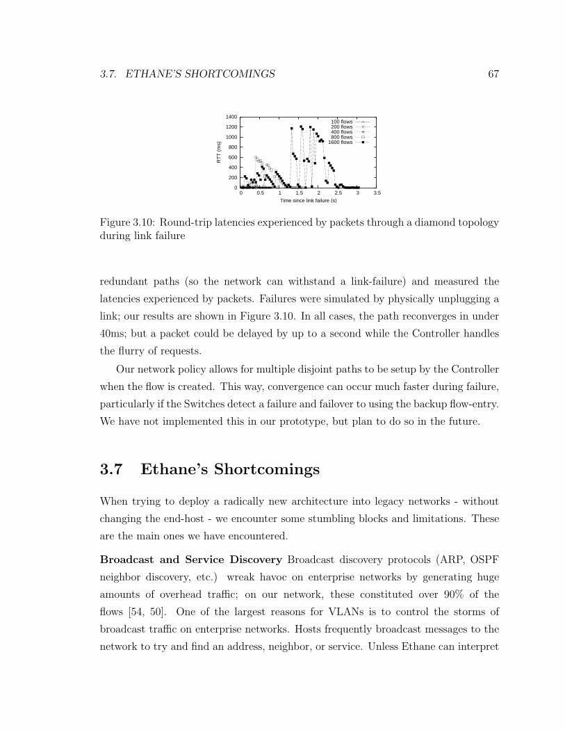
3.7. ETHANE’S SHORTCOMINGS 67
0
200
400
600
800
1000
1200
1400
0 0.5 1 1.5 2 2.5 3 3.5
RT
T (
ms)
Time since link failure (s)
100 flows200 flows400 flows800 flows
1600 flows
Figure 3.10: Round-trip latencies experienced by packets through a diamond topologyduring link failure
redundant paths (so the network can withstand a link-failure) and measured the
latencies experienced by packets. Failures were simulated by physically unplugging a
link; our results are shown in Figure 3.10. In all cases, the path reconverges in under
40ms; but a packet could be delayed by up to a second while the Controller handles
the flurry of requests.
Our network policy allows for multiple disjoint paths to be setup by the Controller
when the flow is created. This way, convergence can occur much faster during failure,
particularly if the Switches detect a failure and failover to using the backup flow-entry.
We have not implemented this in our prototype, but plan to do so in the future.
3.7 Ethane’s Shortcomings
When trying to deploy a radically new architecture into legacy networks - without
changing the end-host - we encounter some stumbling blocks and limitations. These
are the main ones we have encountered.
Broadcast and Service Discovery Broadcast discovery protocols (ARP, OSPF
neighbor discovery, etc.) wreak havoc on enterprise networks by generating huge
amounts of overhead traffic; on our network, these constituted over 90% of the
flows [54, 50]. One of the largest reasons for VLANs is to control the storms of
broadcast traffic on enterprise networks. Hosts frequently broadcast messages to the
network to try and find an address, neighbor, or service. Unless Ethane can interpret
68 CHAPTER 3. ETHANE: A DEPLOYABLE ARCHITECTURE
the protocol and respond on its behalf, it needs to broadcast the request to all poten-
tial responders; this involves creating large numbers of flow-entries, and it leads to
lots of traffic which—if malicious—has access to every end-host. Broadcast discovery
protocols could be eliminated if there was a standard way to register a service where
it can easily be found. SANE proposed such a scheme [29], and in the long-term, we
believe this is the natural way to go.
Application-layer routing A limitation of Ethane is that it has to trust end-hosts
not to relay traffic in violation of the network policy. Ethane controls connectivity
using the Ethernet and IP addresses of the end-points; but Ethane’s policy can be
compromised by communications at a higher layer. For example, if A is allowed to
talk to B but not C, and if B can talk to C, then B can relay messages from A to C.
This could happen at any layer above the IP layer, e.g., P2P application that creates
an overlay at the application layer, or multihomed clients that connect to multiple
networks. This is a hard problem to solve, and most likely requires a change to the
operating system and any virtual machines running on the host.
Knowing what the user is doing Ethane’s policy assumes that the transport port
numbers indicate what the user is doing: port 80 means HTTP, port 25 is SMPT,
and so on. Colluding malicious users or applications can fool Ethane by agreeing
to use non-standard port numbers. And it is common for “good” applications to
tunnel applications over ports (such as port 80) that are likely to be open in firewalls.
To some extent, these will always be problems for a mechanism, like Ethane, that
focuses on connectivity without involvement from the end-host. In the short-term,
we can, and do, insert application proxies along the path (using Ethane’s waypoint
mechanism).
Spoofing Ethernet addresses Ethane Switches rely on the binding between a user
and Ethernet addresses to identify flows. If a user spoofs a MAC address, it might
be possible to fool Ethane into delivering packets to an end-host. This is easily
prevented in an Ethane-only network where each Switch port is connected to one
host: The Switch can drop packets with the wrong MAC address. If two or more
end-hosts connect to the same Switch port, it is possible for one to masquerade as

3.7. ETHANE’S SHORTCOMINGS 69
another. A simple solution is to physically prevent this; a more practical solution in
larger networks would be to use 802.11x to more securely authenticate packets and
addresses.
Chapter 4
Conclusions
This thesis described a new approach to dealing with the security and management
problems found in today’s Enterprise networks. Ethernet and IP networks are not well
suited to address these demands. Their shortcomings are many fold. First, they do
not provide a usable namespace because the name-to-address bindings and address-to-
principle bindings are loose and insecure. Secondly, policy declaration is normally over
low-level identifiers (e.g., IP addresses, VLANs, physical ports and MAC addresses)
that don’t have clear mappings to network principles and are topology dependant.
Encoding topology in policy results in brittle networks whose semantics change with
the movement of components. Finally, policy today is declared in many files over
multiple components. This requires the human operator to perform the labor intensive
and error prone process of manual consistency.
Our proposal addresses these issues by offering a new architecture for Enterprise
networks. Our solution was designed around the following principles. First, the net-
work control functions, including authentication, name bindings, and routing, should
be centralized. This allows the network to provide a strongly bound and authenticated
namespace without the complex consistency management required in a distributed
architecture. Further, centralization simplifies network-wide support for logging, au-
diting and diagnostics. Second, policy declaration should be centralized, and over
high-level names. This both decouples the network topology and the network policy,
and simplifies declaration. Finally, the policy should be able to control the route a
70
71
path takes. This allows the administrator to selectively require traffic to traverse mid-
dleboxes without having to engineer choke points into the physical network topology.
From these guiding principles we have designed and implemented two network
architectures, SANE and Ethane. SANE is a clean-slate architecture in which hosts
must acquire capabilities from a central Controller in order to communicate. The
capabilities encode a policy compliant route for the communication to take. All
switches ensure each packet has a valid capability and is on the permitted route.
While providing strong security guarantees and a flexible policy model, deploying
SANE requires modification to all end-hosts and replacement of all switches and
routers.
To overcome the deployment hurdles presented by SANE we designed, built, and
deployed Ethane. Ethane is a backwards compatible architecture that provides similar
security guarantees to SANE yet does not require modification to end hosts, can
coexist with IP routers and Ethernet switches, and can be incrementally deployed
for incremental benefit. Ethane differs from SANE in that rather than relying on
capabilities, requests for communication are provided by explicitly setting up flows
at each switch along the granted path.
To demonstrate the practicality and explore the limits of a centralized architecture
that makes policy decisions per-flow, we built and deployed Ethane within the campus
network at Stanford University. One of the most interesting consequences of building
a prototype is that the lessons you learn are always different—and usually far more—
than were expected. With our deployment, this is most definitely the case: We learned
lessons about the good and bad properties of Ethane, and fought a number of fires
during our deployment.
The largest conclusion that we draw is that (once deployed) we found it much
easier to manage the Ethane network than we expected. On numerous occasions
we needed to add new Switches, new users, support new protocols, and prevent
certain connectivity. On each occasion we found it natural and fast to add new
policy rules in a single location. There is great peace of mind to knowing that the
policy is implemented at the place of entry and determines the route that packets
take (rather than being distributed as a set of filters without knowing the paths that
72 CHAPTER 4. CONCLUSIONS
packets follow). By journaling all registrations and bindings, we were able to identify
numerous network problems, errant machines, and malicious flows—and associate
them with an end-host or user. This bodes well for network managers who want to
hold users accountable for their traffic or perform network audits.
We have also found it straightforward to add new features to the network: either
by extending the policy language, adding new routing algorithms (such as support-
ing redundant disjoint paths), or introducing new application proxies as waypoints.
Overall, we believe that the most significant advantage of our solution comes from
the ease of innovation and evolution. By keeping the Switches dumb and simple, and
by allowing new features to be added in software on the central Controller, rapid im-
provements are possible. This is particularly true if the protocol between the Switch
and Controller is open and standardized, so as to allow competing Controller software
to be developed. The Controller can be made open-source and run on an open and
widely-used operating system (such as Linux), rather than on the proprietary and
closed OSes used in switches and routers today. Our goal is to put the development
of new Controllers into the hands of network operators and allow them to add new
features they need in a single location, rather than having to replace their whole
network so often.
We are confident that a centralized architecture built around a Controller can
scale to support quite large networks: Our results suggest that a single Controller
could manage over 10,000 machines, which bodes well for whoever has to manage
the Controllers. In practice, we expect Controllers to be replicated in topologically-
diverse locations on the network, yet SANE and Ethane do not restrict how the
network manager does this. Over time, we expect innovation in how fault-tolerance is
performed, perhaps with emerging standard protocols for Controllers to communicate
and remain consistent.
We are convinced that the Switches are best when they are dumb, and contain
little or no management software. Further, the Switches are just as simple at the
center of the network as they are at the edge. Because the Switch consists mostly of
a flow table, it is easy to build in a variety of ways: in software for embedded devices,
in network processors, for rapid deployment, and in custom ASICs for high volume
73
and low-cost. Our results suggest that a SANE or Ethane Switch will be significantly
simpler, smaller, and lower-power than current Ethernet switches and routers.
In the case of Ethane, we anticipate some innovation in Switches. For example,
while our Switches maintain a single FIFO queue, one can imagine a “less-dumb”
Switch with multiple queues, where the Controller decides to which queue a flow
belongs. This leads to many possibilities: per-class or per-flow queueing in support
of priorities, traffic isolation, and rate control. Our results suggest that even if the
Switch does per-flow queueing (which may or may not make sense), the Switch need
only maintain a few thousand queues. This is frequently done in low-end switches
today, and it is well within reach of current technology.
Appendix A
Pol-Eth Description
Overview
An Ethane policy script is composed of three sections:
• Group declarations
• Expressions
• Predicates
Each section is separated by a ’%%’ delimiter on a line of its own. The following
example shows a valid Pol-Eth policy file.
# Group declarations
users = ["jpettit","mfreed"];
%%
# no expressions
%%
# predicates
[(usrc=in("users") ^ (hdst="server") ^ (protocol="ssh_t")] :
allow ;
Declaring Rules
Ethane policy supports groups and nested groups. Groups are simply enumera-
tions of principles, whether users, hosts, protocols or access points. Groups are not
typed and will accept any string value. Group declarations have the following format
74
75
groupname = ["quoted princple name", "quoted princple name" ...
];
Example group declarations are listed below.
laptops = ["martins_laptop","margrets_laptop"];
workstations = ["nity","merced","umpqua","northfork","cranberries"];
computers = [workstations, laptops];
Note that the group “computers” contains all members in groups laptops and
workstations.
Rules
Constraints in Pol-Eth are declared as a set of condition/action rules. Each rule
has a condition which, if true for a given flow, specify that action to apply to that
flow. The format of a rule is:
[(predicate1) ^ (predicate2) ^ predicate3) ... ] : constraint;
Predicates
Rule conditions are defined over a set of predicates, all of which must be true for
the rule to apply to a flow. The general format of a rule is (lhs=rhs), as is shown in
the following examples.
(usrc="username") # user src is "username"
(hdst="nity") # destination host is "nity"
(protocol=["http_t","https_t"]) # protocol is
https or http (hsrc=in("computers")) # source host is in group "computers"
LHS
Pol-Eth supports the following Left Hand Sides (LHS) in predicate declaration.
usrc user source
udst user destination
hsrc host source
hdst host destination
76 APPENDIX A. POL-ETH DESCRIPTION
apsrc source access point
apdst destination access point
datproto datalink protocol
netproto network protocol
transproto transport protocol
bpf accepts an arbitrary bpf expression
expr expression (discussed later)
RHS
With the exceptions noted below, each predicate must have a RHS value that
must match that of a flow for the predicate to be true. Predicate RHS values in
Pol-Eth can have the following forms.
“quoted string” quoted principle name
[“list”,“of”,“quoted”,“strings” ] list of quoted principle names
in(“group”) a member of group “group”
Constraints
For each rule, if the predicate matches a flow, the action associate with the rule
is applied. The following list contains the actions supported in Pol-Eth.
allow/deny Allow or deny the flow without performing any other action.
waypoints=[“list”,“of”,“waypoints” ] require flow to traverse a set of way-
points. Waypoints are traverse in declared order.
protected Only allow outbound-initiated flows from the flow source.
rate-limit=speed Limit flows to the specified rate.
NAT=(pub,priv) Require one of the switches on the flow path to perform L3
address translation.
77
isolation-class=“class name” Place the flow in an isolation class. Flows in
a particular isolation class will only share queues with other flows in the
same class, thus allowing full end to end isolation between flows.
MAT Swap MAC headers at each switch with the purpose of hiding the source
and destination identities.
Precedence
Rule precedence, in the case of overlapping rule declarations, is top to bottom. A
rule declared in a Pol-Eth file will take precedence over all following rules that also
apply to a given flow.
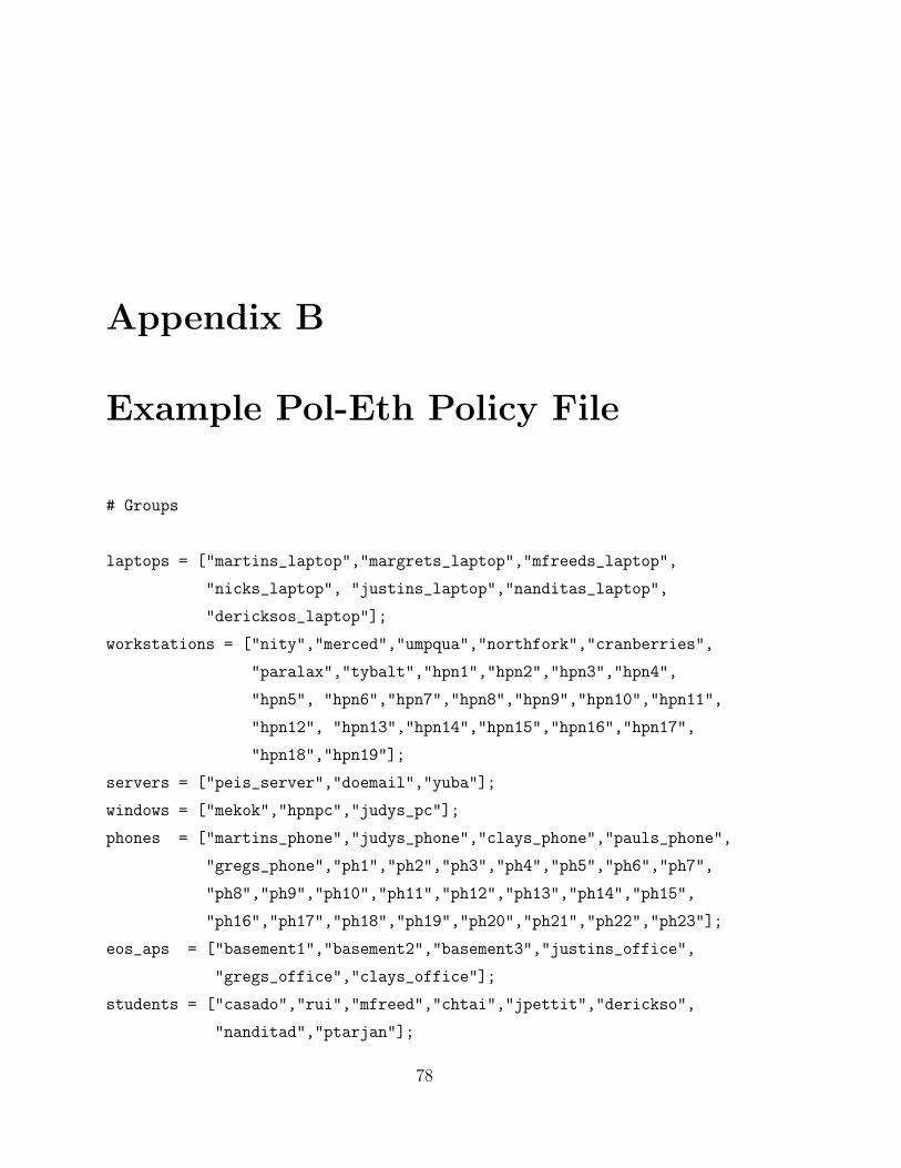
Appendix B
Example Pol-Eth Policy File
# Groups
laptops = ["martins_laptop","margrets_laptop","mfreeds_laptop",
"nicks_laptop", "justins_laptop","nanditas_laptop",
"dericksos_laptop"];
workstations = ["nity","merced","umpqua","northfork","cranberries",
"paralax","tybalt","hpn1","hpn2","hpn3","hpn4",
"hpn5", "hpn6","hpn7","hpn8","hpn9","hpn10","hpn11",
"hpn12", "hpn13","hpn14","hpn15","hpn16","hpn17",
"hpn18","hpn19"];
servers = ["peis_server","doemail","yuba"];
windows = ["mekok","hpnpc","judys_pc"];
phones = ["martins_phone","judys_phone","clays_phone","pauls_phone",
"gregs_phone","ph1","ph2","ph3","ph4","ph5","ph6","ph7",
"ph8","ph9","ph10","ph11","ph12","ph13","ph14","ph15",
"ph16","ph17","ph18","ph19","ph20","ph21","ph22","ph23"];
eos_aps = ["basement1","basement2","basement3","justins_office",
"gregs_office","clays_office"];
students = ["casado","rui","mfreed","chtai","jpettit","derickso",
"nanditad","ptarjan"];
78
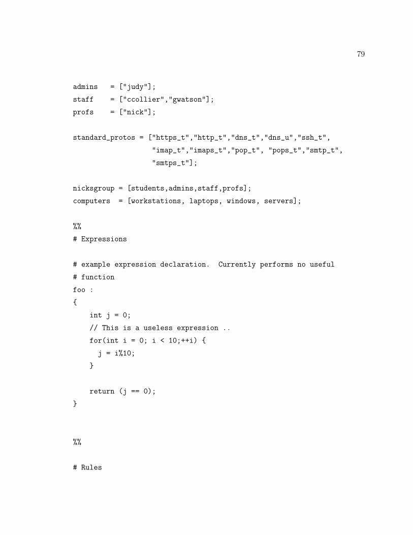
79
admins = ["judy"];
staff = ["ccollier","gwatson"];
profs = ["nick"];
standard_protos = ["https_t","http_t","dns_t","dns_u","ssh_t",
"imap_t","imaps_t","pop_t", "pops_t","smtp_t",
"smtps_t"];
nicksgroup = [students,admins,staff,profs];
computers = [workstations, laptops, windows, servers];
%%
# Expressions
# example expression declaration. Currently performs no useful
# function
foo :
{
int j = 0;
// This is a useless expression ..
for(int i = 0; i < 10;++i) {
j = i%10;
}
return (j == 0);
}
%%
# Rules
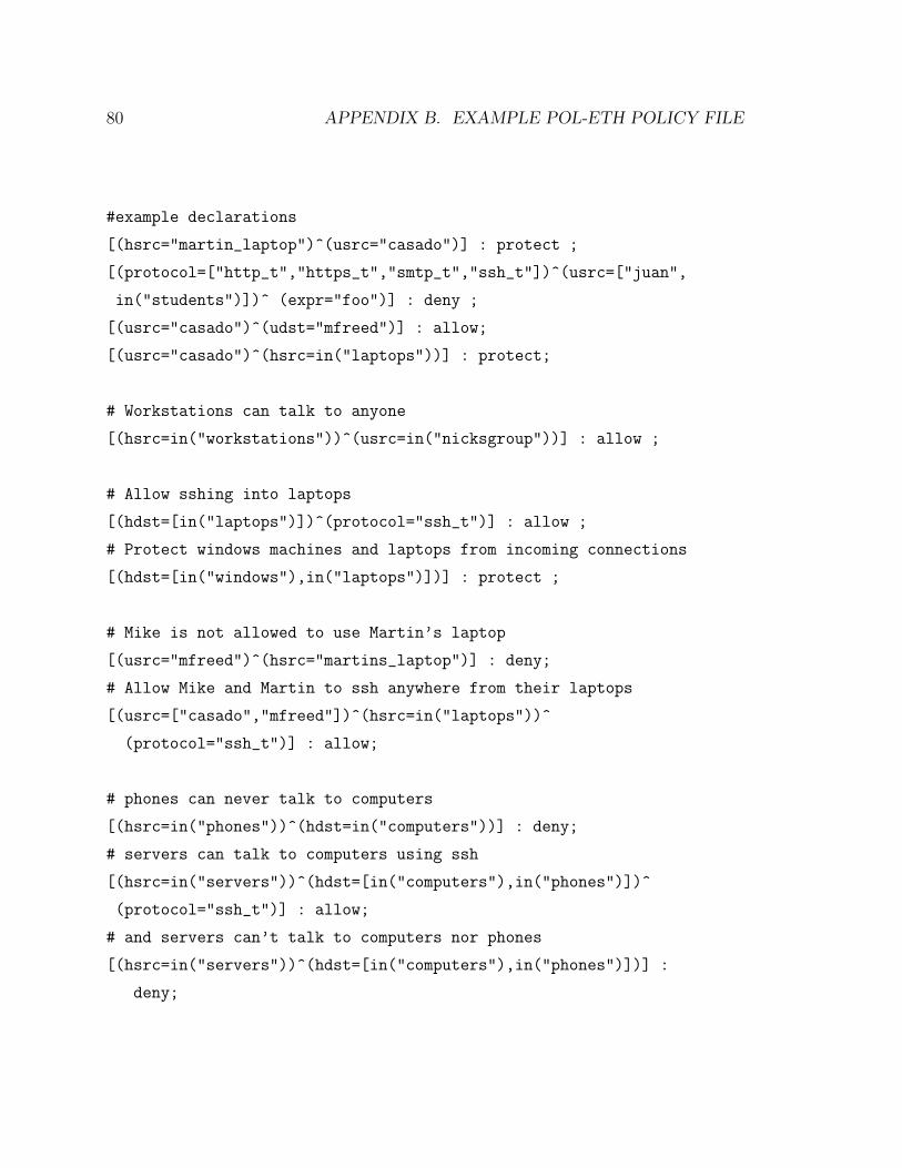
80 APPENDIX B. EXAMPLE POL-ETH POLICY FILE
#example declarations
[(hsrc="martin_laptop")^(usrc="casado")] : protect ;
[(protocol=["http_t","https_t","smtp_t","ssh_t"])^(usrc=["juan",
in("students")])^ (expr="foo")] : deny ;
[(usrc="casado")^(udst="mfreed")] : allow;
[(usrc="casado")^(hsrc=in("laptops"))] : protect;
# Workstations can talk to anyone
[(hsrc=in("workstations"))^(usrc=in("nicksgroup"))] : allow ;
# Allow sshing into laptops
[(hdst=[in("laptops")])^(protocol="ssh_t")] : allow ;
# Protect windows machines and laptops from incoming connections
[(hdst=[in("windows"),in("laptops")])] : protect ;
# Mike is not allowed to use Martin’s laptop
[(usrc="mfreed")^(hsrc="martins_laptop")] : deny;
# Allow Mike and Martin to ssh anywhere from their laptops
[(usrc=["casado","mfreed"])^(hsrc=in("laptops"))^
(protocol="ssh_t")] : allow;
# phones can never talk to computers
[(hsrc=in("phones"))^(hdst=in("computers"))] : deny;
# servers can talk to computers using ssh
[(hsrc=in("servers"))^(hdst=[in("computers"),in("phones")])^
(protocol="ssh_t")] : allow;
# and servers can’t talk to computers nor phones
[(hsrc=in("servers"))^(hdst=[in("computers"),in("phones")])] :
deny;
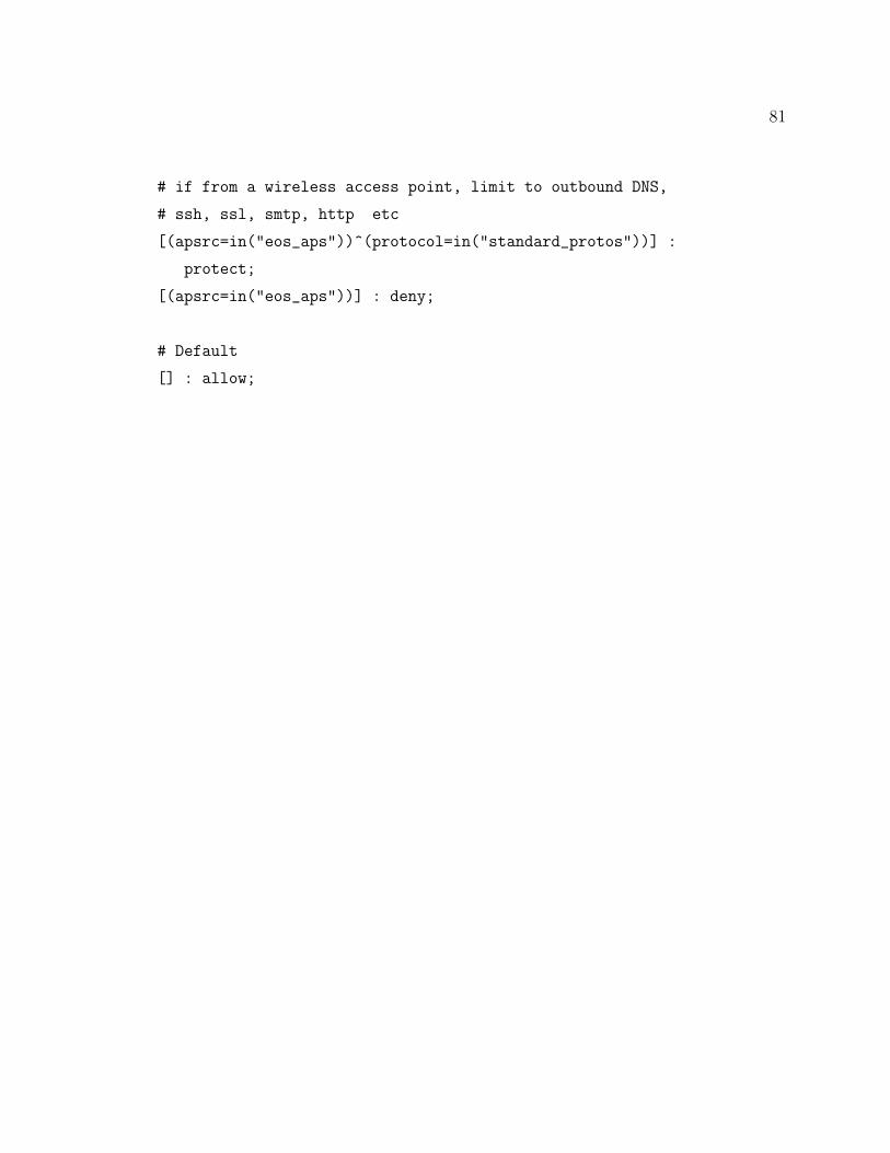
81
# if from a wireless access point, limit to outbound DNS,
# ssh, ssl, smtp, http etc
[(apsrc=in("eos_aps"))^(protocol=in("standard_protos"))] :
protect;
[(apsrc=in("eos_aps"))] : deny;
# Default
[] : allow;
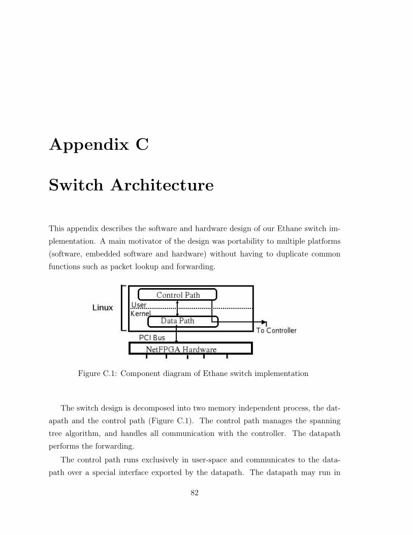
Appendix C
Switch Architecture
This appendix describes the software and hardware design of our Ethane switch im-
plementation. A main motivator of the design was portability to multiple platforms
(software, embedded software and hardware) without having to duplicate common
functions such as packet lookup and forwarding.
Figure C.1: Component diagram of Ethane switch implementation
The switch design is decomposed into two memory independent process, the dat-
apath and the control path (Figure C.1). The control path manages the spanning
tree algorithm, and handles all communication with the controller. The datapath
performs the forwarding.
The control path runs exclusively in user-space and communicates to the data-
path over a special interface exported by the datapath. The datapath may run in
82
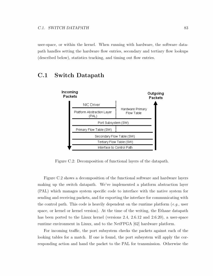
C.1. SWITCH DATAPATH 83
user-space, or within the kernel. When running with hardware, the software data-
path handles setting the hardware flow entries, secondary and tertiary flow lookups
(described below), statistics tracking, and timing out flow entries.
C.1 Switch Datapath
Figure C.2: Decomposition of functional layers of the datapath.
Figure C.2 shows a decomposition of the functional software and hardware layers
making up the switch datapath. We’ve implemented a platform abstraction layer
(PAL) which manages system specific code to interface with the native system for
sending and receiving packets, and for exporting the interface for communicating with
the control path. This code is heavily dependent on the runtime platform (e.g., user
space, or kernel or kernel version). At the time of the writing, the Ethane datapath
has been ported to the Linux kernel (versions 2.4, 2.6.12 and 2.6.20), a user-space
runtime environment in Linux, and to the NetFPGA [62] hardware platform.
For incoming traffic, the port subsystem checks the packets against each of the
looking tables for a match. If one is found, the port subsystem will apply the cor-
responding action and hand the packet to the PAL for transmission. Otherwise the
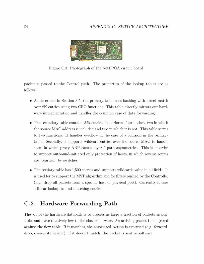
84 APPENDIX C. SWITCH ARCHITECTURE
Figure C.3: Photograph of the NetFPGA circuit board
packet is passed to the Control path. The properties of the lookup tables are as
follows:
• As described in Section 3.5, the primary table uses hashing with direct match
over 8K entries using two CRC functions. This table directly mirrors our hard-
ware implementation and handles the common case of data forwarding.
• The secondary table contains 32k entries. It performs four hashes, two in which
the source MAC address is included and two in which it is not. This table serves
to two functions. It handles overflow in the case of a collision in the primary
table. Secondly, it supports wildcard entries over the source MAC to handle
cases in which proxy ARP causes layer 2 path asymmetries. This is in order
to support outbound-initiated only protection of hosts, in which reverse routes
are “learned” by switches.
• The tertiary table has 1,500 entries and supports wildcards value in all fields. It
is used for to support the MST algorithm and for filters pushed by the Controller
(e.g., drop all packets from a specific host or physical port). Currently it uses
a linear lookup to find matching entries.
C.2 Hardware Forwarding Path
The job of the hardware datapath is to process as large a fraction of packets as pos-
sible, and leave relatively few to the slower software. An arriving packet is compared
against the flow table. If it matches, the associated Action is executed (e.g. forward,
drop, over-write header). If it doesn’t match, the packet is sent to software.
C.2. HARDWARE FORWARDING PATH 85
Our Switch hardware is built on the NetFPGA platform [62] developed in our
group at Stanford University. A NetFPGA card plugs into the PCI slot of a desk-
top PC, and the Switch software runs in Linux on the desktop PC. A NetFPGA
board (shown in Figure C.3) consists of four Gigabet Ethernet interfaces, a Xilinx
Virtex-Pro-50 FPGA, memory (SRAM and DRAM) and a PCI interface to the host
computer. NetFPGA is designed as an open platform for research and teaching us-
ing an industry-standard design flow. Packets can be processed at full line-rate in
hardware.1
In our hardware forwarding path, packets flow through a standard pipeline of
modules. All the modules run in parallel and complete in 16 clock cycles (at 62.5MHz).
The modules check packet lengths, parse packet headers, implement hash functions,
perform lookup functions, track traffic statistics, maintain a flow table in SRAM,
and enable overwrite of packet headers as needed. The main design choice is how to
implement the flow table.
We chose to implement the flow table as hash table (made easy because the flow
table requires only exact-match lookups). In particular, we use double-hashing: we
use two CRC functions to generate two pseudo-random indices for every packet—each
index is used to lookup into a different hash table. This way, we make it very likely
that at least one of the indices will find a unique match. If both hashes return entries
that clash with existing entries, we say there has been a collision, and rely on software
to process the packet.
A block level diagram of the Ethane datapath is illustrated in Figure C.4.
C.2.1 Modules in the Datapath
In Block A, received packets are checked for a valid length, and undersized packets
are dropped.
In preparation for calculating the hash-functions, Block B parses the packet header
to extract the following fields: Ethernet header, IP header, and TCP or UDP header.
1The implementation described here is running on version 2.0 of NetFPGA, and is currentlybeing ported to version 2.1, which runs more than twice as fast. The functional Switch on version2.1 of NetFPGA will be available in summer 2007.
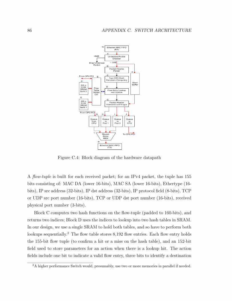
86 APPENDIX C. SWITCH ARCHITECTURE
Figure C.4: Block diagram of the hardware datapath
A flow-tuple is built for each received packet; for an IPv4 packet, the tuple has 155
bits consisting of: MAC DA (lower 16-bits), MAC SA (lower 16-bits), Ethertype (16-
bits), IP src address (32-bits), IP dst address (32-bits), IP protocol field (8-bits), TCP
or UDP src port number (16-bits), TCP or UDP dst port number (16-bits), received
physical port number (3-bits).
Block C computes two hash functions on the flow-tuple (padded to 160-bits), and
returns two indices; Block D uses the indices to lookup into two hash tables in SRAM.
In our design, we use a single SRAM to hold both tables, and so have to perform both
lookups sequentially.2 The flow table stores 8,192 flow entries. Each flow entry holds
the 155-bit flow tuple (to confirm a hit or a miss on the hash table), and an 152-bit
field used to store parameters for an action when there is a lookup hit. The action
fields include one bit to indicate a valid flow entry, three bits to identify a destination
2A higher performance Switch would, presumably, use two or more memories in parallel if needed.
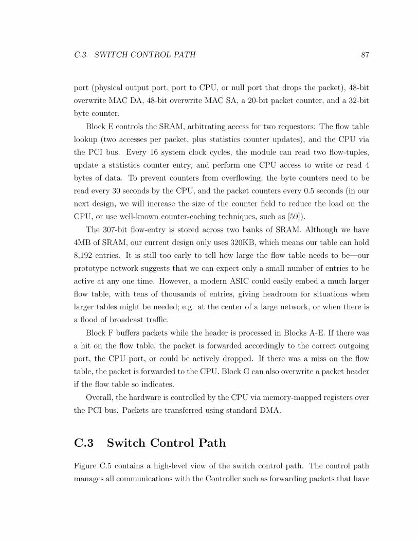
C.3. SWITCH CONTROL PATH 87
port (physical output port, port to CPU, or null port that drops the packet), 48-bit
overwrite MAC DA, 48-bit overwrite MAC SA, a 20-bit packet counter, and a 32-bit
byte counter.
Block E controls the SRAM, arbitrating access for two requestors: The flow table
lookup (two accesses per packet, plus statistics counter updates), and the CPU via
the PCI bus. Every 16 system clock cycles, the module can read two flow-tuples,
update a statistics counter entry, and perform one CPU access to write or read 4
bytes of data. To prevent counters from overflowing, the byte counters need to be
read every 30 seconds by the CPU, and the packet counters every 0.5 seconds (in our
next design, we will increase the size of the counter field to reduce the load on the
CPU, or use well-known counter-caching techniques, such as [59]).
The 307-bit flow-entry is stored across two banks of SRAM. Although we have
4MB of SRAM, our current design only uses 320KB, which means our table can hold
8,192 entries. It is still too early to tell how large the flow table needs to be—our
prototype network suggests that we can expect only a small number of entries to be
active at any one time. However, a modern ASIC could easily embed a much larger
flow table, with tens of thousands of entries, giving headroom for situations when
larger tables might be needed; e.g. at the center of a large network, or when there is
a flood of broadcast traffic.
Block F buffers packets while the header is processed in Blocks A-E. If there was
a hit on the flow table, the packet is forwarded accordingly to the correct outgoing
port, the CPU port, or could be actively dropped. If there was a miss on the flow
table, the packet is forwarded to the CPU. Block G can also overwrite a packet header
if the flow table so indicates.
Overall, the hardware is controlled by the CPU via memory-mapped registers over
the PCI bus. Packets are transferred using standard DMA.
C.3 Switch Control Path
Figure C.5 contains a high-level view of the switch control path. The control path
manages all communications with the Controller such as forwarding packets that have
88 APPENDIX C. SWITCH ARCHITECTURE
Figure C.5: Diagram of packet flow through functional layers of the control path.
failed local lookups, relaying flow setup, tear-down, and filtration requests.
The control path uses the local TCP stack for communication to the Controller.
By design, the datapath also controls forwarding for the local protocol stack. This
ensures that no local traffic leaks onto the network that was not explicitly authorized
by the Controller.
All per-packet functions that do not have per-packet time constraints are imple-
mented within the control path. This ensures that the datapath will be simple, fast
and amenable to hardware design and implementation. Our implementation includes
a DHCP client, the spanning tree protocol stack, a ssl stack for authentication and
encryption of all data to the Controller, and support for flow-learning to support
outbound-initiated only traffic.

Bibliography
[1] 802.1D MAC Bridges. http://www.ieee802.org/1/pages/802.1D-2003.html.
[2] Apani home page. http://www.apani.com/.
[3] Berkeleydb. http://www.oracle.com/database/berkeley-db.html.
[4] Cisco network admission control.
http://www.cisco.com/en/US/netsol/ns466/networking
solutions package.html.
[5] Consentry. http://www.consentry.com/.
[6] DNS Service Discover (DNS-SD). http://www.dns-sd.org/.
[7] Identity engines. http://www.idengines.com/.
[8] Lumeta. http://www.lumeta.com/.
[9] Microsoft network access protection.
http://www.microsoft.com/technet/network/nap/default.mspx.
[10] Openwrt. http://openwrt.org/.
[11] Packetmotion home page. http://www.packetmotion.com/.
[12] Securify. http://www.securify.com/.
[13] Tracking down the phantom host. http://www.securityfocus.com/infocus/1705.
[14] UPnP Standards. http://www.upnp.org/.
89
90 BIBLIOGRAPHY
[15] Zodiac: Dns protocol monitoring and spoofing program.
www.packetfactory.net/projects/zodiac/.
[16] Cisco Security Advisory: Cisco IOS Remote Router Crash.
http://www.cisco.com/warp/public/770/ioslogin-pub.shtml, August 1998.
[17] CERT Advisory CA-2003-13 Multiple Vulnerabilities in Snort Preprocessors.
http://www.cert.org/advisories/CA-2003-13.html, April 2003.
[18] Sasser Worms Continue to Threaten Corporate Productivity.
http://www.esecurityplanet.com/alerts/article.php/3349321, May 2004.
[19] Technical Cyber Security Alert TA04-036Aarchive HTTP Parsing Vulnerabil-
ities in Check Point Firewall-1. http://www.us-cert.gov/cas/techalerts/TA04-
036A.html, February 2004.
[20] ICMP Attacks Against TCP Vulnerability Exploit.
http://www.securiteam.com/exploits/5SP0N0AFFU.html, April 2005.
[21] Tom Anderson, Timothy Roscoe, and David Wetherall. Preventing Inter-
net Denial-of-Service with Capabilities. SIGCOMM Comput. Commun. Rev.,
34(1):39–44, 2004.
[22] Hitesh Ballani, Yatin Chawathe, Sylvia Ratnasamy, Timothy Roscoe, and Scott
Shenker. Off by default! In Proc. 4th ACM Workshop on Hot Topics in Networks
(Hotnets-IV), College Park, MD, November 2005.
[23] Yair Bartal, Alain J. Mayer, Kobbi Nissim, and Avishai Wool. Firmato: A novel
firewall management toolkit. ACM Trans. Comput. Syst., 22(4):381–420, 2004.
[24] Steven M. Bellovin. Distributed firewalls. ;login:, 24(Security), November 1999.
[25] Matt Blaze, Joan Feigenbaum, and Angelos D. Keromytis. Keynote: Trust
management for public-key infrastructures (position paper). In Proceedings of
the 6th International Workshop on Security Protocols, pages 59–63, London, UK,
1999. Springer-Verlag.
BIBLIOGRAPHY 91
[26] E. Brickell, G. Di Crescenzo, and Y. Frankel. Sharing block ciphers. In Proceed-
ings of Information Security and Privacy, volume 1841 of LNCS, pages 457–470.
Springer-Verlag, 2000.
[27] Andrei Z. Broder and Michael Mitzenmacher. Using multiple hash functions to
improve ip lookups. In Proc. INFOCOM, April 2001.
[28] Martın Casado, Michael Freedman, Justin Pettit, Jianying Luo, Nick McKeown,
and Scott Shenker. Ethane: Taking control of the enterprise. In SIGCOMM
Computer Comm. Rev., August 2007.
[29] Martın Casado, Tal Garfinkle, Aditya Akella, Michael J. Freedman, Dan Boneh,
Nick McKeown, and Scott Shenker. SANE: A protection architecture for enter-
prise networks. In USENIX Security Symposium, August 2006.
[30] Martın Casado and Nick McKeown. The Virtual Network System. In Proceedings
of the ACM SIGCSE Conference, 2005.
[31] Miguel Castro and Barbara Liskov. Practical byzantine fault tolerance and proac-
tive recovery. ACM Transactions on Computer Systems (TOCS), 20(4):398–461,
November 2002.
[32] Drew Cullen. Half Life 2 leak means no launch for Christmas.
http://www.theregister.co.uk/2003/10/07/half life 2 leak means/, October
2003.
[33] C. Demetrescu and G. Italiano. A new approach to dynamic all pairs shortest
paths. In Proc. STOC’03, 2003.
[34] Y. Desmedt and Y. Frankel. Threshold cryptosystems. In Advances in Cryptology
- Crypto ’89, 1990.
[35] J. R. Douceur. The Sybil attack. In First Intl. Workshop on Peer-to-Peer Systems
(IPTPS ¡92¿02), March 2002.
92 BIBLIOGRAPHY
[36] Tal Garfinkel, Ben Pfaff, Jim Chow, Mendel Rosenblum, and Dan Boneh. Terra:
A virtual machine-based platform for trusted computing. In Proceedings of the
19th Symposium on Operating System Principles(SOSP 2003), October 2003.
[37] David M. Goldschlag, Michael G. Reed, and Paul F. Syverson. Hiding Routing
Information. In R. Anderson, editor, Proceedings of Information Hiding: First
International Workshop, pages 137–150. Springer-Verlag, LNCS 1174, May 1996.
[38] Albert Greenberg, Gisli Hjalmtysson, David A. Maltz, Andy Myers, Jennifer
Rexford, Geoffrey Xie, Hong Yan, Jibin Zhan, and Hui Zhang. A clean slate 4D
approach to network control and management. In SIGCOMM Computer Comm.
Rev., October 2005.
[39] J. H. Howard, M. L. Kazar, S. G. Menees, D. A. Nichols, M. Satyanarayanan,
R. N. Sidebotham, and M. J. West. Scale and performance in a distributed file
system. ACM Transactions on Computer Systems, 6(1):51–81, February 1988.
[40] Sotiris Ioannidis, Angelos D. Keromytis, Steven M. Bellovin, and Jonathan M.
Smith. Implementing a distributed firewall. In ACM Conference on Computer
and Communications Security, pages 190–199, 2000.
[41] G. C. Shoja Jian Pu, Eric Manning. Routing Reliability Analysis of Partially
Disjoint Paths. In IEEE Pacific Rim Conference on Communications, Computers
and Signal processing (PACRIM’ 01), volume 1, pages 79–82, August 2001.
[42] C. Kaufman. Internet key exchange (ikev2) protocol. draft-ietf-ipsec-ikev2-10.txt
(Work in Progress).
[43] A. Keromytis, S. Ioannidis, M. Greenwald, and J. Smith. The strongman archi-
tecture, 2003.
[44] A. Kumar, V. Paxson, and N. Weaver. Exploiting underlying structure for de-
tailed reconstruction of an internet-scale event. In to appear in Proc. ACM IMC,
October 2005.

BIBLIOGRAPHY 93
[45] M. Leech, M. Ganis, Y. Lee, R. Kuris, D. Koblas, and L. Jones. Socks protocol
version 5. RFC 1928, March 1996.
[46] Tom Markham and Charlie Payne. Security at the Network Edge: A Distributed
Firewall Architecture. In DARPA Information Survivability Conference and Ex-
position, 2001.
[47] Guillermo Mario Marro. Attacks at the data link layer, 2003.
[48] Alain Mayer, Avishai Wool, and Elisha Ziskind. Fang: A firewall analysis engine.
In IEEE Symposium on Security and Privacy, page 177, 2000.
[49] David Moore, Vern Paxson, Stefan Savage, Colleen Shannon, Stuart Staniford,
and Nicholas Weaver. Inside the Slammer Worm. IEEE Security and Privacy,
1(4):33–39, 2003.
[50] Andy Myers, Eugene Ng, and Hui Zhang. Rethinking the service model: Scaling
ethernet to a million nodes. In Proc. HotNets, November 2004.
[51] Peter Newman, Thomas L. Lyon, and Greg Minshall. Flow labelled IP: A con-
nectionless approach to ATM. In INFOCOM (3), 1996.
[52] Ruoming Pang, Mark Allman, Mike Bennett, Jason Lee, Vern Paxson, and Brian
Tierney. A first look at modern enterprise traffic. In Proc. Internet Measurement
Conference, October 2005.
[53] Ruoming Pang, Mark Allman, Vern Paxson, and Jason Lee. The devil and packet
trace anonymization. ACM Comput. Commun. Rev., 36(1), January 2006.
[54] Radia J. Perlman. Rbridges: Transparent routing. In Proc. INFOCOM, March
2004.
[55] Vassilis Prevelakis and Angelos D. Keromytis. Designing an Embedded Fire-
wall/VPN Gatweway. In Proc. International Network Conference, July 2002.
94 BIBLIOGRAPHY
[56] Jennifer Rexford, Albert Greenberg, Gisli Hjalmtysson, David A. Maltz, Andy
Myers, Geoffrey Xie, Jibin Zhan, and Hui Zhang. Network-wide decision making:
Toward a wafer-thin control plane. In Proc. HotNets, November 2004.
[57] Phillip Rogaway, Mihir Bellare, John Black, and Ted Krovetz. OCB: A Block-
Cipher Mode of Operation for Efficient Authenticated Encryption. In ACM
Conference on Computer and Communications Security, pages 196–205, 2001.
[58] Timothy Roscoe, Steve Hand, Rebecca Isaacs, Richard Mortier, and Paul Jardet-
zky. Predicate routing: Enabling controlled networking. SIGCOMM Computer
Comm. Rev., 33(1), 2003.
[59] Devavrat Shah, Sundar Iyer, Balaji Prabhakar, and Nick McKeown. Maintaining
statistics counters in line cards. In IEEE Micro, Jan-Feb 2002.
[60] J. Veizades, E. Guttman, C. Perkins, and S. Kaplan. Service location protocol.
RFC 2165, july 1997.
[61] M. Wahl, T. Howes, and S. Kille. RFC 2251: Lightweight Directory Access
Protocol (v3), December 1997. Status: PROPOSED STANDARD.
[62] Greg Watson, Nick McKeown, and Martın Casado. Netfpga: A tool for network
research and education. In Workshop on Architecture Research using FPGA
Platforms, February 2006.
[63] N. Weaver, D. Ellis, S. Staniford, and V. Paxson. Worms vs. perimeters: The
case for hard-lans. In Proc. Hot Interconnects, August 2004.
[64] Avishai Wool. A quantitative study of firewall configuration errors. IEEE Com-
puter, 37(6):62–67, 2004.
[65] Avishai Wool. The use and usability of direction-based filtering in firewalls.
Computers & Security, 26(6):459–468, 2004.
[66] S. Wu, B. Vetter, and F. Wang. An experimental study of insider attacks for the
OSPF routing protocol. October 1997.
BIBLIOGRAPHY 95
[67] G. Xie, J. Zhan, D. Maltz, H. Zhang, A. Greenberg, G. Hjalmtysson, and J. Rex-
ford. On static reachability analysis of ip networks. In Proc. INFOCOM, March
2005.
[68] Geoffrey Xie, Jibin Zhan, David A. Maltz, Hui Zhang, Albert Greenberg, and
Gisli Hjalmtysson. Routing design in operational networks: A look from the
inside. In Proc. SIGCOMM, September 2004.
[69] A. Yaar, A. Perrig, and D. Song. Siff: A stateless internet flow filter to miti-
gate ddos flooding attacks. In In Proceedings of the IEEE Security and Privacy
Symposium, May 2004.
[70] Hong Yan, T. S. Eugene Ng, David Maltz, Hui Zhang, Hemant Gogineni, and
Zheng Cai. Tesseract: A 4d network control plane. In In 4th USENIX Symposium
on Networked Systems Design & Implementation (NSDI07), April 2007.
![Home []...Auo.usto do Carmo Affonso, casado, Corn- merciante, idem Auousto Lopes da Rocha, casado, proprie- tario, Almofala de Baixo Francisco Rod rigues Ferreira, casado, commerciante,](https://static.fdocuments.in/doc/165x107/6091a8f88edcee4ad757b679/home-auousto-do-carmo-affonso-casado-corn-merciante-idem-auousto-lopes.jpg)