Architecting a vCloud NFV Platform - LearnVMware.online€¦ · Architecting a vCloud NFV Platform...
49
Architecting a vCloud NFV Platform REFERENCE ARCHITECTURE VERSION 2.0
Transcript of Architecting a vCloud NFV Platform - LearnVMware.online€¦ · Architecting a vCloud NFV Platform...
Architecting a vCloud NFV
Platform R E F E R E N C E A R C H I T E C T U R E
V E R S I O N 2 . 0
R E F E R E N C E A R C H I T E C T U R E / 1
Architecting a vCloud NFV Platform
Table of Contents
1. Network Function Virtualization Overview .................................................................. 6
1.1 NFV Infrastructure Working Domain .................................................................. 6
1.2 Management and Orchestration Working Domain ............................................ 7
1.2.1 Virtualized Infrastructure Manager Functional Block ......................................... 7
1.2.2 Virtual Network Function Manager Functional Block ......................................... 7
1.2.3 Network Functions Virtualization Orchestrator Functional Block ....................... 7
1.3 Operations Management Working Domain ....................................................... 7
1.4 Virtualized Network Function Working Domain ................................................. 7
1.5 Operations Support Systems and Business Support Systems Working Domain7
2. Communication Service Provider Requirements........................................................ 8
2.1 Automated Service Delivery .............................................................................. 8
2.2 Operational Intelligence ..................................................................................... 9
2.3 Carrier Grade ..................................................................................................... 9
3. Solution Overview ..................................................................................................... 10
3.1 Technology Mapping ....................................................................................... 10
3.2 NFVI Components Overview ........................................................................... 12
3.3 MANO Components Overview......................................................................... 14
3.3.1 VIM Components ............................................................................................. 14
3.4 Operations Management Components ............................................................ 15
3.5 Virtual Network Functions and VMware vCloud NFV ...................................... 17
4. Reference Architecture ............................................................................................. 18
4.1 Design Principles ............................................................................................. 18
4.1.1 Carrier Grade ................................................................................................... 18
4.1.2 Modularity ........................................................................................................ 19
4.1.3 Service Life Cycle ............................................................................................ 20
4.1.4 Tenant Based Architecture .............................................................................. 20
4.1.5 Integrated Operational Management ............................................................... 21
4.2 Two-Pod Design Overview .............................................................................. 21
4.2.1 Core Platform ................................................................................................... 22
4.2.2 Initial Pod Design and Scaling Considerations ................................................ 26
4.2.3 Secure Multitenancy ........................................................................................ 27
4.2.4 VNF Onboarding .............................................................................................. 28
4.3 Three-Pod Design Overview ............................................................................ 30
4.3.1 Core Platform ................................................................................................... 30
4.3.2 Initial Pod Design and Scaling Considerations ................................................ 33
4.3.3 Secure Multitenancy ........................................................................................ 34
4.3.4 VNF Onboarding In Three-Pod Design ........................................................... 34

R E F E R E N C E A R C H I T E C T U R E / 2
Architecting a vCloud NFV Platform
4.3.5 Using Two-Pod or Three-Pod Design for vCloud NFV .................................... 36
4.4 Operations Management ................................................................................. 37
4.4.1 Operations Workflow ....................................................................................... 37
4.4.2 VMware vRealize Operations Manager ........................................................... 39
4.4.3 VMware vRealize Log Insight .......................................................................... 40
4.4.4 VMware vRealize Network Insight ................................................................... 40
4.4.5 Business Continuity and Disaster Recovery .................................................... 41
4.4.6 VMware vSphere Data Protection ................................................................... 43
4.5 Carrier Grade ................................................................................................... 44
4.5.1 Performance .................................................................................................... 44
R E F E R E N C E A R C H I T E C T U R E / 3
Architecting a vCloud NFV Platform
Figures
Figure 1: The ETSI NFV Architectural Framework ............................................................. 6
Figure 2: Functional Elements Mapping to ETSI NFV Reference Model ......................... 10
Figure 3: VIM Hierarchy in VMware vCloud NFV .............................................................. 14
Figure 4: VMware vCloud NFV Logical Building Blocks ................................................... 19
Figure 5: Two-Pod Design Overview ................................................................................ 21
Figure 6: VMware vCenter Two-Pod Design .................................................................... 22
Figure 7: VMware NSX Manager in a Two-Pod Design ................................................... 23
Figure 8: VMware vCloud NFV Distributed Virtual Switch Design .................................... 24
Figure 9: VMware vCloud Director in a Two-Pod Design ................................................. 25
Figure 10: VMware vCloud Director Multitenant Networking in a Two-Pod Design ......... 27
Figure 11: VMware vCloud Director Resource Partitioning in a Two-Pod Design ............ 28
Figure 12: VNF Onboarding in a Two-Pod Design ........................................................... 29
Figure 13: Three-Pod Design Overview ............................................................................ 30
Figure 14: VMware vCenter Three-Pod Design ................................................................ 31
Figure 15: VMware NSX Manager in a Three-Pod Design ............................................... 31
Figure 16: Virtual Networking Design for Edge Pod and Resource Pod Connectivity...... 32
Figure 17: VMware vCloud Director in a Three-Pod Design ............................................. 33
Figure 18: VMware vCloud Director Multitenant Networking in a Three-Pod Design ....... 34
Figure 19: VNF Onboarding in a Three-Pod Design ......................................................... 35
Figure 20: VNF Networking in a Three-Pod Design.......................................................... 35
Figure 21: VMware vCloud NFV Operations Management Design .................................. 38
Figure 22: VMware vCloud NFV Design for Data Performance ....................................... 46
R E F E R E N C E A R C H I T E C T U R E / 4
Architecting a vCloud NFV Platform
Tables
Table 1: VMware vCloud NFV 2.0 Reference Architecture Document Structure ............... 5
Table 2: VMware vCloud NFV Components ..................................................................... 11
Table 3: NFVI Operations Management Components ...................................................... 37
Table 4: NFVI Business Continuity and Disaster Recovery Components ........................ 41

R E F E R E N C E A R C H I T E C T U R E / 5
Architecting a vCloud NFV Platform
Executive Summary
This reference architecture provides guidance for designing and creating a greenfield Network Functions
Virtualization (NFV) platform. This second version of the VMware vCloud® NFVTM platform consolidates the
experience gained in real world deployments, with new product and solution capabilities, to create a platform
to support communication service providers in realizing the goals of Network Functions Virtualization:
automating the deployment of network services, reducing network infrastructure costs, deploying network
services quickly, and maintaining carrier grade service quality.
vCloud NFV is compliant with the European Telecommunications Standards Institute (ETSI) Network
Functions Virtualisation (NFV); Architectural Framework. The platform is based on VMware components that
are tightly integrated and tested. Each of the components has numerous potentially valid configurations, but
only a few of these configurations result in a cohesive and robust functional system that meets business and
technical requirements, and aligns with the ETSI NFV Architectural Framework.
The VMware vCloud NFV 2.0 platform delivers the following ETSI NFV architectural components:
• NFV Infrastructure (NFVI)
• Virtualized Infrastructure Manager (VIM)
• NFVI Operations Management
These components, their interaction with each other, and the way in which they meet communication service
provider requirements, are described in this reference architecture.
Audience
This document is written to guide telecommunications and solution architects, sales engineers, field
consultants, advanced services specialists, and customers who are responsible for virtualized network
services and the NFV environment on which they run.
Document Structure
This document is divided into four chapters listed in Table 1.
S E C TI O N DE S C RI P TI ON
Network Function
Virtualization
Overview
This section of the document introduces the core concepts of the ETSI
NFV Architectural Framework.
Communication
Service Provider
Requirements
This section of the document describes the requirements of an NFVI
platform from the perspective of the Communication Service Provider
(CSP).
Solution Overview This section of the document provides an overview of the components
used to build the vCloud NFV platform.
Reference
Architecture This section of the document describes how components are combined
to deliver an NFV platform.
Table 1: VMware vCloud NFV 2.0 Reference Architecture Document Structure

R E F E R E N C E A R C H I T E C T U R E / 6
Architecting a vCloud NFV Platform
1. Network Function Virtualization Overview
NFV is an architectural framework developed by the ETSI NFV Industry Specification Group. The framework
aims to transform the telecommunications industry through lower costs, rapid innovation, and scale. The
framework provides a standardized model that moves away from proprietary, purpose-built hardware
dedicated to a single service, toward network functions delivered through software virtualization as VNFs
with commercial off-the-shelf (COTS) hardware. The result is a network that is more agile and better able to
respond to the on-demand, dynamic needs of telecommunications traffic and services. The framework
identifies functional blocks and the main reference points between such blocks. Some of these are already
present in current deployments, while others need to be added to support the virtualization process and
operation.
Figure 1 shows the ETSI NFV Architectural Framework, depicting the functional blocks and reference points
in the NFV framework. Each functional block is shown by solid lines and is within the scope of NFV. The
architectural framework is complemented by the NFVI Operations Management functional block, which is
not part of the standard framework. This block is essential to run a production platform. The Operations
Management functional block is separated from the Virtualized Infrastructure Manager (VIM) based on best
practices and deployment experience. The architectural framework focuses on the functions and capabilities
necessary for the virtualization and operation of a CSP’s network. Functional blocks above the dotted red
line are not in the scope of this paper.
Figure 1: The ETSI NFV Architectural Framework
1.1 NFV Infrastructure Working Domain The Network Functions Virtualization Infrastructure (NFVI) working domain is the foundational layer of the
NFV. It provides the virtual compute, storage, and network infrastructure, and the physical compute,
storage, and network infrastructure, on which VNFs are deployed and executed. NFVI nodes are deployed
in multiple sites and regions to provide service high-availability and to support locality and workload latency
requirements. The virtualization layer provided by the hypervisor allows for workloads that are agnostic to
the underlying hardware. With this approach, operators choose hardware from their preferred vendors, at
competitive prices, and upgrade hardware independent of its workloads.
R E F E R E N C E A R C H I T E C T U R E / 7
Architecting a vCloud NFV Platform
1.2 Management and Orchestration Working Domain The Management and Orchestration (MANO) working domain covers the orchestration and life cycle
management of physical and software resources. These elements support the infrastructure virtualization
and life cycle management of MANO VNFs, with a focus on the virtualization specific management tasks
necessary to the NFV framework.
1.2.1 Virtualized Infrastructure Manager Functional Block
The Virtualized Infrastructure Manager (VIM) is a functional block of the MANO working domain and is
responsible for controlling, managing, and monitoring the NFVI compute, storage, and network resources. It
exposes this functionality northbound to allow VNF Managers and NFV Orchestrators the ability to deploy
and manage VNFs. It exercises the same functionality southbound to the hypervisors and controllers in the
NFVI. The VIM manages the allocation and release of virtual resources, and the association of virtual to
physical resources, including the optimization of such resources. The complete inventory of the NFVI is
maintained in the VIM, including the linkage and relationship between components as they relate to an
instance of a VNF workload, to allow for monitoring in the context of a single VNF. The VIM provides the API
that allows the VNF Manager to manage the complete life cycle of VNFs.
1.2.2 Virtual Network Function Manager Functional Block
This document does not cover the Virtual Network Function Manager (VNFM) functional block. For
information about the VNFM functional block, refer to the publicly available ETSI NFV specifications.
1.2.3 Network Functions Virtualization Orchestrator Functional Block
This document does not cover the NFV Orchestrator (NFVO) functional block. For information about the
NFVO functional block, refer to the publicly available ETSI NFV specifications.
1.3 Operations Management Working Domain The NFVI Operations Management components are considered part of a functional block of the MANO
working domain and are responsible for providing and extending visibility for fault, configuration, accounting,
performance, and security (FCAPS) of the NFVI. These northbound reporting components provide
infrastructure alarms, events, and measurable metrics relating to the NFVI working domain and VNF
workloads. The implementation of vCloud NFV expands the capabilities of this functional block through a
portfolio of solutions that includes business continuity and disaster recovery (BCDR) capabilities across the
MANO working domain.
1.4 Virtualized Network Function Working Domain This document does not cover the Virtualized Network Function (VNF) working domain. For information
about the VNF working domain, refer to the publicly available ETSI NFV specifications.
1.5 Operations Support Systems and Business Support Systems Working Domain
The vCloud NFV platform exposes application programmable interfaces (APIs) that can be consumed from
one or multiple operations support systems and business support systems (OSS/BSS). These are not
described in this document. For information about APIs that can be consumed from the OSS/BSS working
domain, refer to the publicly available ETSI NFV specifications.

R E F E R E N C E A R C H I T E C T U R E / 8
Architecting a vCloud NFV Platform
2. Communication Service Provider Requirements
More and more Communication Service Providers (CSPs) are using vCloud NFV to embark on a journey to
modernize and transform networks and services with virtualized software components. Collected
requirements help shape the current and future releases of the vCloud NFV solution. These key
requirements are introduced in this section and will be discussed in detail in the Reference Architecture
section of this document.
CSPs have specific requirements of NFVI, VIM, and FCAPS elements, based on the need to demonstrate
progress in an NFV deployment while generating revenue from the virtual domain. For this reason, a great
deal of focus is given to the ability to easily, programmatically, and repeatedly deploy services from a
service component catalog. Since CSPs deliver services that are often regulated by local governments,
carrier grade aspects of these services, such as high availability and deterministic performance, are also
included in this list. CSPs must ensure that managing the NFVI and the deployed virtualized network
functions is tightly integrated in the solution.
The following sections explain the requirements in further detail.
2.1 Automated Service Delivery One of the benefits of virtualization is the ability to centrally orchestrate the deployment of service building
blocks from a software catalog, as opposed to using proprietary appliances. Instead of sending engineers to
a site to install physical devices, Virtual Network Functions (VNFs), also known as service components, are
selected from a catalog. By clicking a button, the new service is installed. To reach this level of simplicity,
the NFV platform must support the following:
• Quick VNF Onboarding. VNF onboarding is automated using enhanced, policy based vApp templating
and declarative abstract resource requirements for underlying compute, storage, and networking
resources.
• Programmatic VNF Provisioning. The speed and efficiency of VNF deployment is increased through
automation, selecting service operations from a catalog of VNFs to deploy specific services.
• True Multitenant Isolation. Physical resources abstracted into virtual resource pools are shared
between services and customers, referred to as tenants of the platform. The ability to partition the
service and VNF from each other is key to ensure performance and quality of service (QoS) across the
platform.
• Service Life Cycle Management. Programmatic service creation and dynamic orchestration of running
VNFs are required pieces of an automation framework. Interfaces between the VIM, the VNFM, and the
NFV Orchestrator (NFVO) must leverage a robust and open API. Using these interfaces the NFV
platform deploys, scales, restarts, and decommissions VNFs as needed.
• Dynamic Optimization. As more and more VNFs are deployed on the NFVI, NFVI resources must be
able to proactively act on specific operations. Since the NFV environment is software based, the system
must be able to move VNF components to balance fair and optimized resource utilization. NFVI
resiliency is improved with proactive monitoring and automation – from scalability of resource pools to
avoid issues, to policy based workload placement.

R E F E R E N C E A R C H I T E C T U R E / 9
Architecting a vCloud NFV Platform
2.2 Operational Intelligence Building an NFVI and managing VNFs effectively is a primary requirement for all CSPs. Operation and
management of the NFV environment must be tightly integrated with the other benefits of the solution. The
functions CSPs require include:
• Discovery and Reconciliation. The NFV platform must automatically discover the network and service
topologies across the physical and virtual domains, and reconcile runtime states as they change. The
NFVI, VNFs, and VNF components (VNFCs) must be entirely visible to the operating personnel.
• Performance and Capacity Monitoring. Continuous system performance monitoring must provide a
holistic view of key performance indicators such as interface utilization, data rates, capacity demand,
service-level agreement (SLA) violations, and component availability. The same system must be
intelligent and provide capacity and performance forecasts with actionable recommendations.
• Issue Isolation and Remediation. The platform must provide near real-time root cause analysis, and
meaningful alerting for fast remediation and proactive issue avoidance.
• Workflow Automation and Expansion. The monitoring platform must be expandable to allow
integration with new data source consumption and coexistence with other elements such as OSS,
service orchestration, service assurance, and big data analytics. Where possible, the monitoring system
must provide a way to add third-party expansion modules for higher layer monitoring, such as VoIP and
video quality.
2.3 Carrier Grade CSPs deliver certain services that are considered critical to infrastructure and are therefore tightly regulated
by many governments. These regulations force a level of service quality to which over-the-top (OTT)
providers do not adhere. CSPs must conform to specific service quality metrics, for example resolving
service disruptions quickly and automatically without packet loss affecting service quality. The same applies
to services offered from a CSP to enterprise customers. Service quality is at the core of brand protection
and customer experience management. As such, SLAs require the delivery of carrier grade quality services.
The following examples are essential NFV platform requirements for carrier grade systems:
• High Availability and Resiliency. The platform must provide integrated high availability and fault
tolerance across the NFVI, virtual, and management domains. In the event of a failure, the platform
must be able to self-heal to maximize service uptime. Mean Time To Failure (MTTF) must increase over
the lifetime of the platform through adaptive, proactive, and automated monitoring systems. Mean Time
To Repair (MTTR) must decrease over the lifetime of the NFV environment, as the system is optimized
and proactive alerting takes place.
• Performance. The platform must achieve deterministic performance. The amount of resources required
to deliver a certain level of performance must be well understood. Data plane intensive VNFs must be
supported by the same components as control and management plane VNFs.
• Scalability. CSPs expect growth in the number of customers and services deployed on the NFV
platform. The platform must be able to provide long term scale out capabilities, and dynamic and short
term scale up and scale out functions.
• NFVI Life Cycle (Patching and Upgrades). The platform must be patched and upgraded by using
optimized change management approaches for zero to minimal downtime.

R E F E R E N C E A R C H I T E C T U R E / 1 0
Architecting a vCloud NFV Platform
3. Solution Overview
The VMware vCloud NFV 2.0 platform is an evolution of the VMware NFV solution, based on extensive
customer deployment and the continued development of standards organizations such as the European
Telecommunications Standards Institute (ETSI). The vCloud NFV platform provides a comprehensive,
service-oriented solution, leveraging a cloud computing model that allows ubiquitous, programmatic, on-
demand access to a shared pool of compute, network, and storage resources. The solution is integrated
with holistic operations management and service assurance capabilities, empowering the operator to rapidly
deliver services while ensuring their quality. With a fully integrated VIM, the same vCloud NFV infrastructure
delivers a myriad of telecommunications use cases, and facilitates reusability of the service catalog based
VNFs.
The vCloud NFV platform delivers a complete, integrated solution that has been rigorously tested to ensure
compatibility, robustness, and functionality. Components used in creating the solution are currently deployed
across many industries and scenarios. vCloud NFV software components can be used in a variety of ways
to construct a comprehensive, end-to-end solution that meets the business goals of CSPs. This document
discusses one way components can be used to create a vCloud NFV architecture.
3.1 Technology Mapping The vCloud NFV platform is an ETSI compliant, fully integrated, modular, multitenant NFV platform. It meets
the ETSI NFV framework, which covers the virtualization layer of the NFVI and the VIM. vCloud NFV
expands on the ETSI NFV framework by integrating robust operations management and intelligence
components to provide the operator with complete platform visibility and monitoring functionality.
This document focuses on the NFVI layer, the VIM components, and the NFV platform operations
management. Figure 2 depicts the mapping between the vCloud NFV functional elements and the ETSI
NFV reference model.
Figure 2: Mapping Functional Elements to ETSI NFV Reference Model

R E F E R E N C E A R C H I T E C T U R E / 1 1
Architecting a vCloud NFV Platform
The vCloud NFV bundle packages together, in a single SKU, the essential building blocks to deploy an NFVI
and VIM platform featuring the newest releases of VMware production proven solutions. Table 2 lists the
components of vCloud NFV and their alignment with the ETSI NFV framework.
COM P O NE N T
INC L UD E D I N
V C LO UD N F V
BUN D LE
RE Q UI RE D IN
S O LU T I ON
E TS I
FU NC T I ON AL
BL O CK
VMware ESXi™ Yes Required NFVI
VMware vCenter ® Server
Appliance™ No* Required VIM
VMware vSphere® Replication™ Yes Recommended NFVI
Operations
VMware vSphere® Data
Protection™ Yes Recommended
NFVI
Operations
VMware vSAN™
Standard Edition Yes Recommended NFVI
VMware vRealize® Operations™
Advanced Yes Required
NFVI
Operations
VMware vRealize® Network
Insight™ No Recommended
NFVI
Operations
VMware vRealize® Log Insight™ Yes Required NFVI
Operations
VMware vCloud Director® for
Service Providers Yes Required VIM
VMware NSX® for vSphere® No Required NFVI
VMware NSX® Manager™ No Required VIM
VMware Site Recovery
Manager™ No Recommended
NFVI
Operations
Table 2: VMware vCloud NFV Components
* VMware vCenter Server® is sold separately per instance, but can be downloaded from the VMware Product Download page.
R E F E R E N C E A R C H I T E C T U R E / 1 2
Architecting a vCloud NFV Platform
3.2 NFVI Components Overview The vCloud NFV infrastructure components use ESXi to virtualize the compute resources, NSX for vSphere
to provide virtual networking, and vSAN for storage. Together, these components create the virtualization
layer described by the ETSI NFV framework. The virtualization layer of the NFVI provides the following
functions:
• Physical Resource Abstraction. Using the software component layers between physical hardware
and the VNFs, physical resources are abstracted. This provides a standardized software based platform
for running VNFs, regardless of the underlying hardware. As long as the CSP uses certified physical
components, VNFs can be deployed by the carrier at the point of presence (POP), distributed, or
centralized data center.
• Physical Resource Pooling. Physical resource pooling occurs when vCloud NFV presents a logical
virtualization layer to VNFs, combining the physical resources into one or more resource
pools. Resource pooling together with an intelligent scheduler facilitates optimal resource utilization,
load distribution, high availability, and scalability. This allows for fine grained resource allocation and
control of pooled resources based on the specific VNF requirements.
• Physical Resource Sharing. In order to truly benefit from cloud economies, the resources pooled and
abstracted by a virtualization layer must be shared between various network functions. The
virtualization layer provides the functionality required for VNFs to be scheduled on the same compute
resources, colocated on shared storage, and to have network capacity divided among them. The
virtualization layer also ensures fairness in resource utilization and usage policy enforcement.
The following components constitute the virtualization layer in the NFVI domain:
Compute – VMware ESXi
ESXi is the hypervisor software used to abstract physical x86 server resources from the VNFs. Each
compute server is referred to as a host in the virtual environment. ESXi hosts are the fundamental compute
building blocks of vCloud NFV. ESXi host resources can be grouped together to provide an aggregate set of
resources in the virtual environment, called a cluster. Clusters are used to logically separate between
management components and VNF components and are discussed at length in the Reference Architecture
section of this document.
ESXi is responsible for carving out resources needed by VNFs and services. ESXi is also the
implementation point of policy based resource allocation and separation, through the use of VMware
vSphere® Distributed Resource SchedulerTM (DRS), an advanced scheduler which balances and ensures
fairness in resource usage in a shared environment.
Since ESXi hosts VNF components in the form of virtual machines (VMs), it is the logical place to implement
VM based high availability, snapshotting, migration with VMware vSphere ® vMotion®, file based backups,
and VM placement rules. ESXi hosts are managed by vCenter Server Appliance, described as one of the
VIM components in the VIM Components section of this document.
An example of one of the new high availability mechanisms available with VMware vCloud NFV 2.0 is
Proactive High Availability (HA). While VMware vSphere® High Availability can rapidly restore VNF
components if a host fails, Proactive HA has tighter integration with several server health monitoring
systems, which means that VNF components can be migrated away from a host whose health is degrading.
This function is realized using vSphere vMotion to move live, running workloads to healthy hosts. vSphere
vMotion is also used to facilitate maintenance tasks and load balancing among hosts in a cluster, with no or
minimal service disruption.
R E F E R E N C E A R C H I T E C T U R E / 1 3
Architecting a vCloud NFV Platform
Storage – VMware vSAN
vSAN is the native vSphere storage component in the NFVI virtualization layer, providing a shared storage
pool between hosts in the cluster. With vSAN, storage is shared by aggregating the local disks and flash
drives attached to the host. Although third-party storage solutions with storage replication adapters that
meet VMware storage compatibility guidelines are also supported, this reference architecture discusses only
the vSAN storage solution.
It is a best practice recommendation that each cluster within vCloud NFV is configured to use a shared
storage solution. When hosts in a cluster use shared storage, manageability and agility improve.
Network – VMware NSX for vSphere
The third component of the NFV infrastructure is the virtualized networking component, NSX for
vSphere. NSX for vSphere allows CSPs to programmatically create, delete, and restore software based
virtual networks. These networks are used for communication between VNF components, and to give
customers dynamic control of their service environments. Dynamic control is provided through tight
integration between the VIM layer and NSX for vSphere. Network multitenancy is also implemented using
NSX for vSphere, by assigning different customers their own virtual networking components and providing
different network segments to each.
Just as ESXi abstracts the server resources, NSX for vSphere provides a layer of abstraction by supporting
an overlay network with standards based protocols. This approach alleviates the limitations of traditional
network segregation technologies such as VLANs, while creating strict separation between management,
customer, and service networks. NSX for vSphere is designed as three independent layers: the data plane,
the control plane, and the management plane. The data plane and control plane layers are described in the
bullet points below, while the management plane is described in the VIM Components section of this
document.
• VMware NSX® Virtual Switch™. The NSX Virtual Switch is a distributed data plane component within
the ESXi hypervisor kernel that is used for the creation of logical overlay networks, facilitating flexible
workload placement of the VNF components. The NSX Virtual Switch is based on the
VMware vSphere® Distributed Switch™ (VDS) and extends VDS functionality by adding distributed
routing, a logical firewall, and enabling VXLAN bridging capabilities. The NSX Virtual Switch is central to
network virtualization, as it enables logical networks that are independent of physical constructs, such
as VLANs. The NSX Virtual Switch is a multilayer switch and therefore supports Layer 3 functionality to
provide optimal routing between subnets directly within the host, for communication within the data
center.
Stateful firewall services are supported by the NSX Virtual Switch through the distributed firewall service
known as microsegmentation. This functionality provides firewall policy enforcement within the
hypervisor kernel at the granularity of the virtual Network Interface Card (vNIC) level on a VNF
component, thereby supporting fine grainednetwork multitenancy.
• VMware NSX® Edge™. The NSX Edge acts as the centralized virtual appliance for routing traffic in to
and out of the virtual domain, toward other virtual or physical infrastructure. This is referred to as
North-South communication. In its role in vCloud NFV design, the NSX Edge is installed as an Edge
Services Gateway (ESG). The ESG is used to provide routing, firewalling, network address translation
(NAT), and other services to the consumers of the NFVI platform. These NSX ESG instances, together
with NSX Virtual Switches, provide true logical tenant isolation.
• VMware NSX® Controller™. The NSX Controller is the control plane responsible for the creation of the
logical topology state necessary for connectivity between the components that form a VNF. Consisting
of three active virtual controller appliances, the NSX Controller nodes form a cluster to maintain NSX
Controller availability. The NSX Controller communicates with the ESXi hosts to maintain connectivity to
the data plane components using out-of-band connectivity.
R E F E R E N C E A R C H I T E C T U R E / 1 4
Architecting a vCloud NFV Platform
3.3 MANO Components Overview As described in the Management and Orchestration Working Domain section of this reference architecture,
the ETSI NFV Management and Orchestration (MANO) framework consists of three functional blocks: the
Virtualized Infrastructure Manager (VIM), the NFV Orchestrator (NFVO), and the VNF Manager (VNFM).
The vCloud NFV platform includes an integrated VIM, which exposes well documented northbound
interfaces to VNFMs and NFVOs. VNFM components are often packaged together with VNFs. NFVO
partners and independent VNFM solutions are listed on the VMware Network Functions Virtualization
Telecommunication Solutions page.
3.3.1 VIM Components
Three components form the VIM functionality in vCloud NFV: the vCenter Server Appliance, the NSX
Manager, and the vCloud Director for Service Providers.
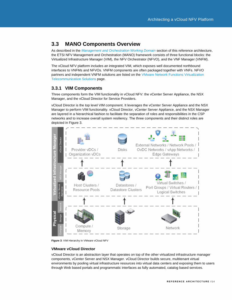
vCloud Director is the top level VIM component. It leverages the vCenter Server Appliance and the NSX
Manager to perform VIM functionality. vCloud Director, vCenter Server Appliance, and the NSX Manager
are layered in a hierarchical fashion to facilitate the separation of roles and responsibilities in the CSP
networks and to increase overall system resiliency. The three components and their distinct roles are
depicted in Figure 3.
Figure 3: VIM Hierarchy in VMware vCloud NFV
VMware vCloud Director
vCloud Director is an abstraction layer that operates on top of the other virtualized infrastructure manager
components, vCenter Server and NSX Manager. vCloud Director builds secure, multitenant virtual
environments by pooling virtual infrastructure resources into virtual data centers and exposing them to users
through Web based portals and programmatic interfaces as fully automated, catalog based services.

R E F E R E N C E A R C H I T E C T U R E / 1 5
Architecting a vCloud NFV Platform
A fundamental concept in vCloud Director is that of the tenant. A tenant is a logically isolated construct
representing a customer, department, network function, or service, used to deploy VNF workloads. vCloud
Director isolates administrative boundaries into NFVI tenants. VNF workload resource consumption is
therefore segregated from other VNF workloads, even though the VNFs may share the same resources.
The pooled resources used by vCloud Director are grouped into two abstraction layers:
• Provider Virtual Data Centers. A provider virtual data center (PvDC) combines the compute and
memory resources of a single vCenter Server resource pool with the storage resources of one or more
datastores available to that resource pool. This construct is the highest in the vCloud Director resource
catalog hierarchy.
• Organization Virtual Data Centers. An organization virtual data center (OvDC) provides resources to
an NFVI tenant and is partitioned from a provider virtual data center. OvDCs provide an environment
where virtual systems can be stored, deployed, and operated. They also provide storage for virtual
media such as ISO images, VNF templates, and VNF component templates.
vCloud Director implements the open and publicly available vCloud API, which provides compatibility,
interoperability, and programmatic extensibility to network equipment providers (NEPs) and their VNF
Managers. The vCloud Director capabilities can be extended to create adaptors to external systems
including OSS/BSS.
VMware vCenter Server
The VMware vCenter Server® is the centralized management interface for compute and storage resources
in the NFVI. It provides an inventory of allocated virtual to physical resources, manages inventory related
information, and maintains an overview of the virtual resource catalogs. vCenter Server also collects data
detailing the performance, capacity, and state of its inventory objects. vCenter Server exposes
programmatic interfaces to other management components for fine grainedcontrol, operation, and
monitoring of the underlying virtual infrastructure.
A resource pool is a logical abstraction which aggregates the use of vCenter Server resources. Multiple
resource pools, grouped into hierarchies, can be used to partition available CPU and memory
resources. The resource pool allows the operator to compartmentalize all resources in a cluster and, if
necessary, delegate control over a specific resource pool to other organizations or network functions. The
operator can also use resource pools to isolate resources used by one service or function from others.
VMware NSX Manager
The NSX Manager is the primary management plane interface for configuration of network resources within
the NFVI. The NSX Manager is responsible for the deployment and management of the virtualized network
components, and functions used to support the creation of network services by the VNFs. Such functions
include network segments, routing, firewalling, and load balancing, etc.
3.4 Operations Management Components The vCloud NFV solution includes six components that together provide a holistic approach to operations
management functionality for the NFV infrastructure of a Communication Service Provider (CSP). Together,
the vRealize Operations, vRealize Log Insight, vRealize Network Insight, Site Recovery Manager,
vSphere Replication, and vSphere Data Protection components monitor the health of the virtualization
infrastructure, collect its logs and alarms, correlate events across multiple data sources and components to
predict future issues, leverage the policy based automation framework to conduct remediation, and analyze
data to help with health prediction and capacity planning.

R E F E R E N C E A R C H I T E C T U R E / 1 6
Architecting a vCloud NFV Platform
The key operations management tasks carried out by these components are:
• NFVI Visibility. NFVI visibility is achieved by collecting key performance and capacity metrics from the
entire virtualization layer, the physical devices, and the VIM components. When problems occur, the
operator can uncover the root cause and determine its location quickly, reducing the Mean Time To
Repair (MTTR).
• Fault Collection and Reporting. The components used in the NFV environment, in the physical
infrastructure, the virtualization layer, or even the VNFs themselves, generate various log messages
and alarms. vCloud NFV includes an integrated log collection system that can correlate between alerts
and log messages to quickly troubleshoot issues.
• Performance Management and Capacity Planning. Ongoing management of performance and
capacity across the NFVI is required for optimal and economic usage of the platform. The performance
management capability helps identify degraded performance before VNFs are affected. This leaves the
operator with enough time to take corrective measures, increasing the Mean Time To Failure (MTTF).
• Optimization. The operations management components analyze system usage and proactively provide
optimization recommendations, including network topology modifications.
The specific components responsible for operations and management are:
VMware vRealize Operations Manager
VMware vRealize® Operations ManagerTM delivers intelligent operations management with full stack visibility
across physical and virtual infrastructures. Through integrated performance and health monitoring functions,
vRealize Operations Manager improves system performance, avoids service disruption, and helps the CSP
provide proactive management of the NFVI infrastructure. The key capabilities that enable these benefits
include predictive analytics, smart and configurable alerts, and user guided remediation. With policy based
automation, operations teams automate key processes to improve the NFV environment operations.
The vRealize Operations Manager extends to collect information through management packs. Information
collected is filtered for relevancy, analyzed, and presented in the form of customizable dashboards. The
monitoring solution exposes an API that retrieves performance and health data pertaining to the NFVI, and
the virtual resources that make up the VNF instance, through an external system.
Out of the box, vRealize Operations Manager does not monitor VNF service availability or VNF internal
KPIs. The VNF Manager derives this information through direct interaction with the respective VNFs.
However, VNF vendors can write their own management packs, known as plugins in vRealize Operations
Manager, to extend functionality to the VNF application. In doing so, the vRealize Operations Manager
becomes a single pane of glass from which the operator manages all components required to construct a
virtual network service.
vRealize Operations Manager exposes the information it gathers through an API that can be consumed by
OSS/BSS, or integrated directly with other MANO components.
VMware vRealize Log Insight
vRealize Log Insight delivers heterogeneous and highly scalable log management with intuitive, actionable
dashboards, sophisticated analytics, and broad third party extensibility. It provides deep operational visibility
and faster troubleshooting across physical, virtual, and cloud environments. Its innovative indexing and
machine learning based grouping enables fast log searches that aid in quickly troubleshooting issues.
vRealize Log Insight ingests large amounts of syslog data from the physical and virtual NFVI components, to
deliver near real-time monitoring, search, and log analytics. It automatically identifies structure from all types
of machine generated log data, including application logs, network traces, configuration files, messages,
performance data, and system state dumps to build a high performance index for analytics purposes.
Coupled with a highly intuitive dashboard for stored queries, reports, and alerts, vRealize Log Insight assists
R E F E R E N C E A R C H I T E C T U R E / 1 7
Architecting a vCloud NFV Platform
the operator in speedy root cause analysis and reduction in Mean Time To Repair (MTTR).
The vRealize Log Insight API provides programmatic access to vRealize Log Insight functionality, and to its
datastore. As a result the OSS/BSS systems or MANO components can integrate with vRealize Log Insight
to gain further insight into the system events and logs.
VMware vRealize Network Insight
vRealize Network Insight collects metrics, log data, network topology, and event data to provide a detailed
view of the network configuration and its health. Information is collected on all NSX managed networks,
including East-West traffic between VNF components, and North-South traffic in to and out of the NFV
infrastructure. Broad Layer 2 to Layer 3 support means that vRealize Network Insight can visualize both the
underlay and the overlay networks, providing the operator with a holistic view into all relevant network
layers. Using this information, the operator can optimize network performance and increase its availability
with visibility and analytics across all virtual and physical elements.
VMware Site Recovery Manager
Site Recovery Manager works in conjunction with various storage replication solutions, including vSphere
Replication, to automate the process of migrating, recovering, testing, and failing back virtual machine
workloads for disaster recovery across multiple sites.
VMware vSphere Replication
vSphere Replication is a virtual machine data protection and disaster recovery solution. It is fully integrated
with vCenter Server and VMware vSphere® Web Client, providing host-based, asynchronous replication of
virtual machines including their storage.
VMware vSphere Data Protection
vSphere Data Protection is used for backup and recovery. It is fully integrated with vCenter Server and
VMware vSphere® Web Client, providing disk-based backup of virtual machines and applications. It
conserves storage usage by using standard deduplication techniques.
Third-party backup solutions that are certified for use with VMware vSphere can be used instead.
3.5 Virtual Network Functions and VMware vCloud NFV vCloud NFV provides VNFs with network, compute, and storage virtual infrastructure resources, for the
deployment and creation of network services. VMware operates the VMware Ready for NFV accreditation
program, in which functional interoperability between partner VNFs and vCloud NFV virtualization layers and
VIMs are tested. The program verifies that VNFs can use CSP relevant functionality, available on vCloud
NFV, and ensures that the partner VNFs understand how to use it.
VMware maintains a list of VNFs that have participated in the VMware Ready for NFV program and are
verified for interoperability with the platform. This list is located on the VMware Solution Exchange.

R E F E R E N C E A R C H I T E C T U R E / 1 8
Architecting a vCloud NFV Platform
4. Reference Architecture
This reference architecture provides a template for creating an ETSI compliant vCloud NFV platform to
support the rapid deployment of virtualized network services across different sites and regions. The
architecture is designed in accordance with these principles:
• To be a carrier grade solution offering performance and high availability
• With modularity of infrastructure, VNFs, and services
• To support a service life cycle with rapid VNF onboarding and automation
• As a tenant based architecture with reusable services, policy driven service components, and resource
reservation
• For integrated operation management monitoring and analysis of the entire NFV environment
4.1 Design Principles The five architectural pillars on which VMware vCloud NFV 2.0 stands are driven by VMware customer
requirements and the individual component capabilities. These are described in more detail in the following
sections of this document.
4.1.1 Carrier Grade
The vCloud NFV platform components are used by a variety of VMware customers from industries such as
large enterprise, health care, and finance. Carrier grade capabilities are continuously added to the platform
to address the requirements of VMware CSP customers. With this release, improvements in high availability
and performance are fundamental to the vCloud NFV design.
Improving the data plane forwarding performance of the platform to meet carrier grade requirements for
specific VNFs such as vEPC and vRouter is accomplished by providing dedicated CPU resources where
needed, and identifying and resolving slow data plane paths. VMware vCloud NFV 2.0 includes specific
functionality to enable VNFs that require precise and dedicate resource allocation to receive it.
The carrier grade design principle of High Availability (HA) is divided into two different layers in the NFV
environment:
• Platform High Availability. Platform HA ensures that the components needed to manage the NFV
environment are always configured in a redundant fashion, replicating data across multiple storage
elements and databases. Ensuring that the management components in the platform are always
available and self-healing allows the operations team to focus on the services and service constructs.
• VNF High Availability. The vCloud NFV platform provides native resiliency functions that can be
consumed by VNFs to increase their availability. For VNFs that do not provide their own high availability
mechanisms, VMware vCloud NFV 2.0 offers advanced support to ensure that a VNF component failure
can be quickly recovered and the boot sequence orchestrated to meet the VNF logic.
With these two availability principles, both the NFV platform and VNFs minimize service disruption.
R E F E R E N C E A R C H I T E C T U R E / 1 9
Architecting a vCloud NFV Platform
4.1.2 Modularity
Architecting vCloud NFV using well defined modules allows the CSP to accelerate deployment and reliably
expand it when needed. The vCloud NFV components are grouped into three distinct containments:
• Management Functions. Management functions are required to manage the NFV Infrastructure and
the Virtual Network Functions (VNFs). MANO components, FCAPS functionality and ancillary elements
such as DNS and OSS/BSS are grouped into this category.
• Edge Functions. The edge functions provide a logical networking delineation between Virtual Network
Functions and external networks. Network traffic transitioning between the physical domain and the
virtual domain is processed by these functions. An example of such a function is NSX Edge Services
Gateway (ESG).
• Resource Functions. The VNFs and functions related to VNFs, such as VNF Managers, are grouped
into this category.
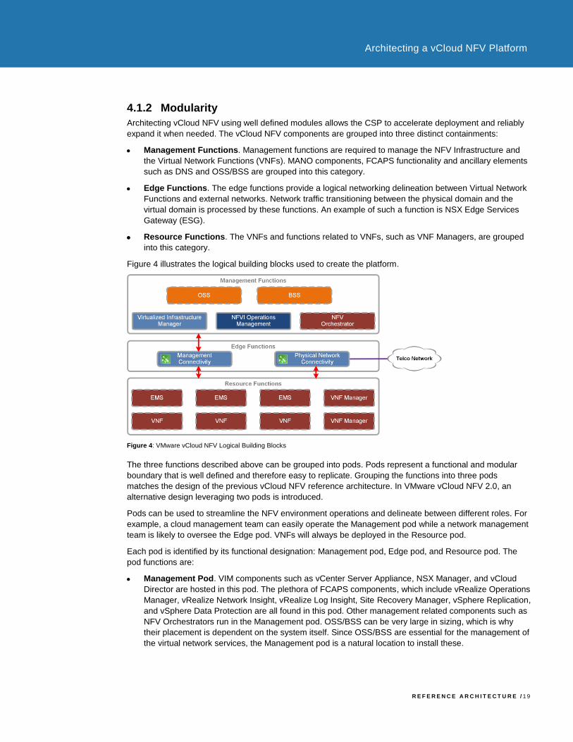
Figure 4 illustrates the logical building blocks used to create the platform.
Figure 4: VMware vCloud NFV Logical Building Blocks
The three functions described above can be grouped into pods. Pods represent a functional and modular
boundary that is well defined and therefore easy to replicate. Grouping the functions into three pods
matches the design of the previous vCloud NFV reference architecture. In VMware vCloud NFV 2.0, an
alternative design leveraging two pods is introduced.
Pods can be used to streamline the NFV environment operations and delineate between different roles. For
example, a cloud management team can easily operate the Management pod while a network management
team is likely to oversee the Edge pod. VNFs will always be deployed in the Resource pod.
Each pod is identified by its functional designation: Management pod, Edge pod, and Resource pod. The
pod functions are:
• Management Pod. VIM components such as vCenter Server Appliance, NSX Manager, and vCloud
Director are hosted in this pod. The plethora of FCAPS components, which include vRealize Operations
Manager, vRealize Network Insight, vRealize Log Insight, Site Recovery Manager, vSphere Replication,
and vSphere Data Protection are all found in this pod. Other management related components such as
NFV Orchestrators run in the Management pod. OSS/BSS can be very large in sizing, which is why
their placement is dependent on the system itself. Since OSS/BSS are essential for the management of
the virtual network services, the Management pod is a natural location to install these.

R E F E R E N C E A R C H I T E C T U R E / 2 0
Architecting a vCloud NFV Platform
• Edge Pod. As described in the Solution Overview section of this document, the virtual network NFVI
building block is based on NSX for vSphere. NSX ESG, hosted in the form of a virtual machine
appliance in this pod, handles all connectivity to the physical domain in the architecture. Other edge
functions can also be hosted in this pod based on the operator needs. The type of networking traffic that
traverses the Edge pod is referred to as North-South traffic.
• Resource Pod. Virtual Network Functions (VNFs) and their managers (VNFM) are placed in the
Resource pod. The VNFs then form the virtual network service.
• Edge / Resource Pod. With this release, we introduce a new construct that combines the Edge pod
and Resource pod functionality into a single collapsed pod. The Edge / Resource pod hosts both the
service constructs (VNFs) and the networking components they need.
Using this collapsed pod function, two designs are possible: two-pod and three-pod. The two-pod design is described in detail in the Two-Pod Design Overview section of this document, while the three-pod design is covered in the Three-Pod Design Overview section. Guidance is provided on the use cases best fitting each of the designs in the Using Two-Pod or Three-Pod Design for vCloud NFV section of the document.
4.1.3 Service Life Cycle
The service life cycle design principle focuses on ease, and the speed at which VNFs can be consumed by
the NFV platform, maintained over their life time, and deployed when needed. The VIM facilitates this
approach and enables the CSP to perform common tasks to benefit from virtualizing network functions.
VNF vendors package their VNFs and deliver them to the CSP in a consumable form. CSPs can then
quickly onboard a VNF to vCloud Director to speed up deployment, and to ensure that VNFs are
consistently behaving in a predictable fashion in each deployment.
Once the VNF is onboarded, it is placed in a catalog that can be consumed based on the CSP policies. The
goal of placing a VNF in the vCloud Director catalog is to enable the NFVO, responsible for creating the
service, to quickly and programmatically deploy the service components required to run the service. vCloud
Director also addresses life cycle activities such as deployment, decommissioning, and restarting service
components.
Since many operational activities around VNFs are performed using higher layer components such as the
VNFM and VNFO, the vCloud NFV platform provides a well documented northbound API that can be used
by these components to complete the service life cycle.
4.1.4 Tenant Based Architecture
The NFVI is shared between multiple entities, referred to as tenants of the NFVI. A fundamental aspect of
the design is ensuring that multiple tenants remain logically isolated from each other, although the physical
and virtual layers they use may be shared. The design principles for multitenancy are:
• An NFVI tenant cannot interfere with the operations of another tenant, nor can one VNF interfere with
another.
• Fair resource sharing must take place. When the system has available resources, and tenants require
these resources, they are split appropriately among the tenants.
• One tenant network must be isolated from another. A tenant choice of IP allocation, default gateway,
and routing, cannot interfere with another tenant. In fact, another tenant may use the same networking
information. Network access from one tenant to another must follow the trusted networking and security
policy of the CSP.
• A tenant must be proactively monitored to ensure health and efficiency to deliver optimal service quality.
R E F E R E N C E A R C H I T E C T U R E / 2 1
Architecting a vCloud NFV Platform
The design principles allow multiple tenants to share resources on the operator’s network, and to maintain a
great deal of control and self-management. Tenants can use overlapping IP addressing and, together with
the use of resource policies, the CSP can ensure that the amount of resources required by the tenant is
controlled. The tenant based architecture together with a well-defined process for VNF onboarding and VNF
resource allocation, means that a CSP can offer service-level agreements (SLAs) with which high quality,
mission critical services, can be created. With the integrated operational management principles, SLAs can
also be monitored and ensured.
4.1.5 Integrated Operational Management
The multilayer, multi-vendor nature of the NFV environment can lead to increase operational management
complexity. To resolve this complexity, vCloud NFV is integrated with a robust operational management
system that monitors and analyzes components involved in the NFV environment. When the physical
servers and switches include monitoring adaptors for the VMware operational management components,
the entire system, including the virtualization layer and the VNF themselves, can be automatically
discovered, monitored, and analyzed.
Designing the monitoring system to provide visibility into the entire environment requires the ability to
integrate data collection from VMware software components alongside third-party elements such as VNFs,
routers, switches, servers, and storage elements. This complete visibility is achieved using a suite of
software components described in the Operations Management Components section of this document.
The data collected is continuously analyzed, which allows for near real-time monitoring. This results in
robust performance monitoring that enables the operator to perform detailed capacity management. Since
the monitoring system is tightly integrated with the VIM, virtualization, and physical layers, proactive failure
avoidance is implemented by leveraging vRealize Operations Manager analytics and DRS. In cases where a
problem does occur root cause analysis can easily be performed, since the operator has holistic visibility
into the entire system.
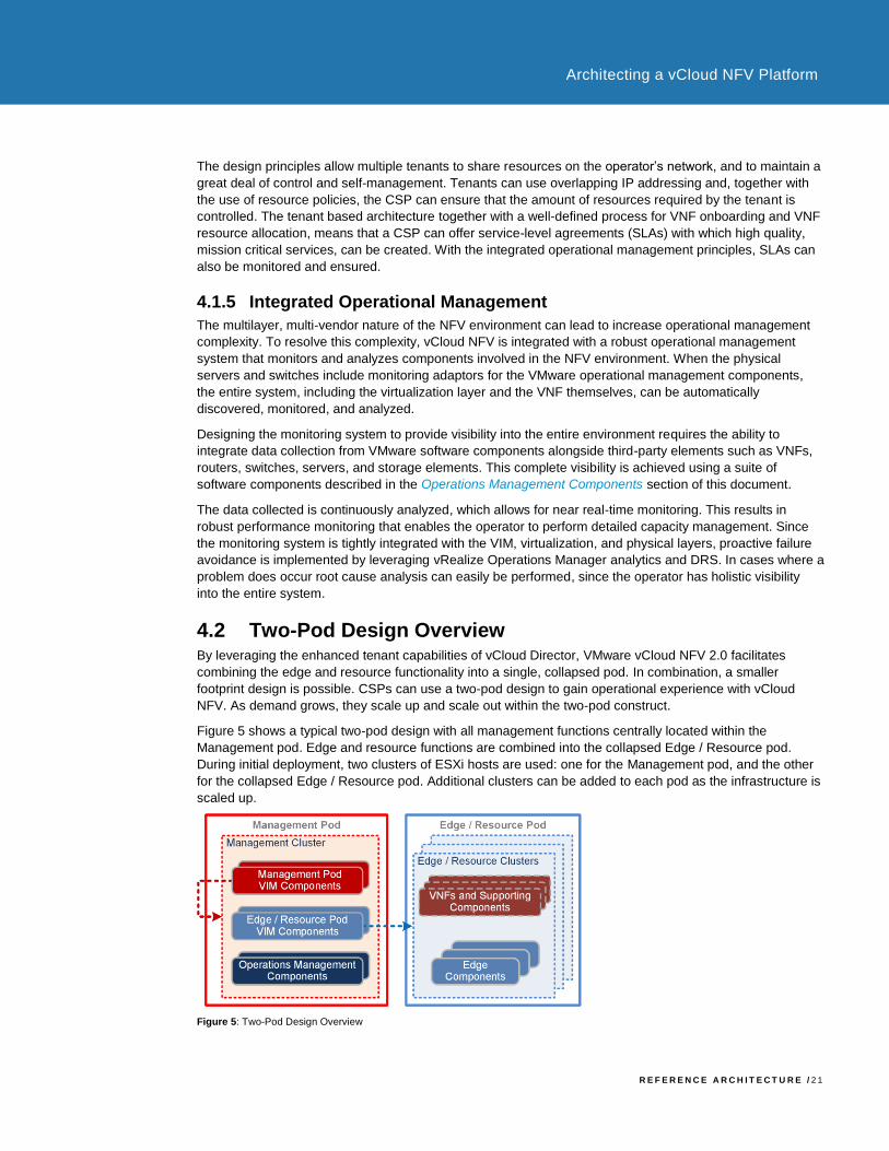
4.2 Two-Pod Design Overview By leveraging the enhanced tenant capabilities of vCloud Director, VMware vCloud NFV 2.0 facilitates
combining the edge and resource functionality into a single, collapsed pod. In combination, a smaller
footprint design is possible. CSPs can use a two-pod design to gain operational experience with vCloud
NFV. As demand grows, they scale up and scale out within the two-pod construct.
Figure 5 shows a typical two-pod design with all management functions centrally located within the
Management pod. Edge and resource functions are combined into the collapsed Edge / Resource pod.
During initial deployment, two clusters of ESXi hosts are used: one for the Management pod, and the other
for the collapsed Edge / Resource pod. Additional clusters can be added to each pod as the infrastructure is
scaled up.
Figure 5: Two-Pod Design Overview

R E F E R E N C E A R C H I T E C T U R E / 2 2
Architecting a vCloud NFV Platform
Within the Management pod, a set of components is deployed to manage the pod itself. These components
include an instance of vCenter Server Appliance, Platform Services Controllers (PSCs), and an instance of
NSX Manager. A 1:1 relationship is required between NSX Manager and vCenter Server. Ancillary
components necessary for the healthy operation of the platform, such as Label Distribution Protocol (LDP)
and Domain Name System (DNS), are also deployed in the Management pod. The tenant-facing Virtualized
Infrastructure Manager (VIM) component, vCloud Director, is located in the Management pod, and is
connected to the vCenter Server and NSX Manager responsible for the Edge / Resource pod.
Also within the management pod, a separate instance of vCenter Server is deployed to manage the
Edge/Resource pod, which uses its own PSCs. Likewise, a separate NSX Manager is deployed to maintain
the 1:1 relatioship to the vCenter Server. The Edge / Resource pod hosts all edge functions, VNFs, and
VNFMs. The edge functions in the pod are NSX ESGs used to route traffic between different tenants and to
provide North-South connectivity.
Since both edge functions and VNF functions are combined in a single pod, resource utilization of this pod
must be carefully monitored. For example, an increase in the number of tenants will inevitably expand the
number of edge resources used. The Operations Management design section of this document discusses
the approach to resource capacity management for this case. When resources are limited, Edge / Resource
pod scale up operations must be carefully coordinated.
The vCloud Director layer of abstraction, and the ability to partition resources in vSphere, facilitate an
important aspect of a shared NFV environment: secure multitenancy. Secure multitenancy ensures that
more than one consumer of the shared NFV platform can coexist on the same physical infrastructure,
without an awareness of, ability to influence, or ability to harm one another. With secure multitenancy
resources are over-subscribed, yet fairly shared and guaranteed as necessary. This is the bedrock of the
NFV business case. Implementation of secure multitenancy is described in the Secure Multitenancy section
of this document. Tenants using the two-pod based NFV environment are able to configure their own virtual
networking functionality and autonomously prepare VNFs for service usage.
4.2.1 Core Platform
This section describes the core componets of the two-pod design, as well as, scaling factors, VNF
onboarding, and the creation of secure multitenancy.
4.2.1.1. VMware vCenter Design
Figure 6 shows the vCenter Server instances and their relationship to the two-pod design.
Figure 6: VMware vCenter Two-Pod Design
In two-pod design, the Management pod is implemented as a cluster, governed by the first vCenter Server
R E F E R E N C E A R C H I T E C T U R E / 2 3
Architecting a vCloud NFV Platform
instance. The use of a cluster allows the components of the pod to benefit from cluster features such as
resource management, high availability, and resiliency, to form the foundation of a carrier grade virtual
infrastructure management. A second vCenter Server is deployed in the Management pod to oversee the
Edge / Resource pod.
Each vCenter Server is a virtual appliance deployed with an embedded database. The vCenter Server
Appliance (VCSA) is preconfigured, hardened, and fast to deploy. Use of the appliance allows for a
simplified design, eases management, and reduces administrative efforts. VCSA availability is ensured
using a three-node cluster. This consists of one active node that serves client requests, one passive node
as backup in the event of failure, and one quorum node referred to as the witness node. Replication
between nodes ensures that VCSA data is always synchronized and up-to-date.
The Platform Services Controller (PSC) contains common infrastructure security services such as VMware
vCenter® Single Sign-On, VMware Certificate Authority, licensing, and server reservation and certificate
management services. The PSC handles identity management for administrators and applications that
interact with the vSphere platform. Each pair of PSCs is configured to use a separate
vCenter Single Sign-On domain. This approach secures the management components by maintaining
administrative separation between the two pods. PSCs are deployed as load balanced appliances external
to vCenter Server for high availability. An NSX ESG instance is used as the load balancer between the
PSCs and their respective vCenter Servers.
Each vCenter Server instance and its PSC data retention is ensured using the native backup service built
into the appliances. This backup is performed to a separate storage system using network protocols such as
SFTP, HTTPS, and SCP.
Local storage drives on the ESXi hosts are pooled into a highly available shared vSAN datastore for
optimum utilization of storage capacity. Each cluster has its own vSAN datastore, an abstracted
representation of the storage into which virtual machine persistent data is stored. All management
components are stored in the management cluster datastore, while VNF workloads deployed from vCloud
Director are stored in the resource cluster datastore. This allows for the separation of administrative,
performance, and failure storage boundaries for management and VNF workloads.
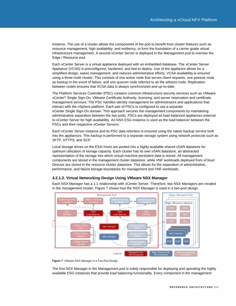
4.2.1.2. Virtual Networking Design Using VMware NSX Manager
Each NSX Manager has a 1:1 relationship with vCenter Server. Therefore, two NSX Managers are created
in the management cluster. Figure 7 shows how the NSX Manager is used in a two-pod design.
Figure 7: VMware NSX Manager in a Two-Pod Design
The first NSX Manager in the Management pod is solely responsible for deploying and operating the highly
available ESG instances that provide load balancing functionality. Every component in the management
R E F E R E N C E A R C H I T E C T U R E / 2 4
Architecting a vCloud NFV Platform
cluster, which relies on multiple external services such as PSCs and vCloud Director cells, uses the ESG as
a load balancer to ensure reachability should a component fail.
The second NSX Manager in the Management pod is responsible for all Edge / Resource pod networking. It
is registered with vCloud Director to provide networking services to tenants, including stateful firewalls and
load balancers. The same NSX Manager is used to configure East-West VNF connectivity, North-South
routing, and out-of-band management access for VNFs.
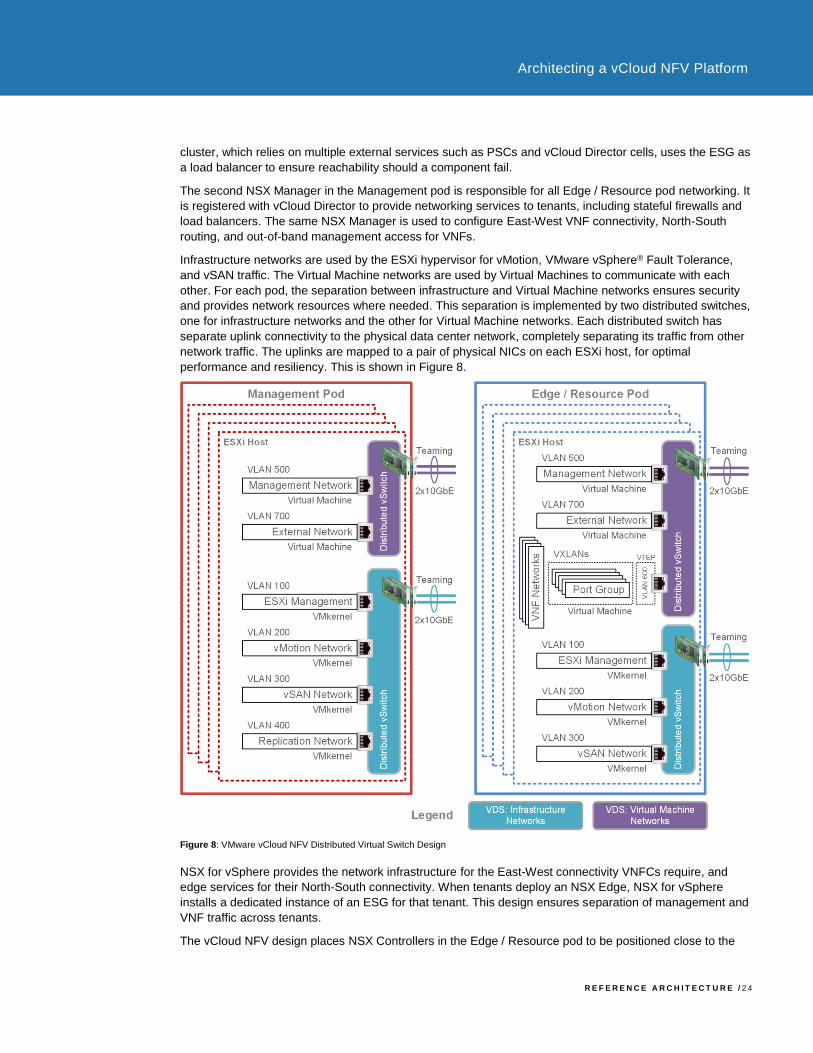
Infrastructure networks are used by the ESXi hypervisor for vMotion, VMware vSphere® Fault Tolerance,
and vSAN traffic. The Virtual Machine networks are used by Virtual Machines to communicate with each
other. For each pod, the separation between infrastructure and Virtual Machine networks ensures security
and provides network resources where needed. This separation is implemented by two distributed switches,
one for infrastructure networks and the other for Virtual Machine networks. Each distributed switch has
separate uplink connectivity to the physical data center network, completely separating its traffic from other
network traffic. The uplinks are mapped to a pair of physical NICs on each ESXi host, for optimal
performance and resiliency. This is shown in Figure 8.
Figure 8: VMware vCloud NFV Distributed Virtual Switch Design
NSX for vSphere provides the network infrastructure for the East-West connectivity VNFCs require, and
edge services for their North-South connectivity. When tenants deploy an NSX Edge, NSX for vSphere
installs a dedicated instance of an ESG for that tenant. This design ensures separation of management and
VNF traffic across tenants.
The vCloud NFV design places NSX Controllers in the Edge / Resource pod to be positioned close to the

R E F E R E N C E A R C H I T E C T U R E / 2 5
Architecting a vCloud NFV Platform
data plane components of the NFVI platform. Three controllers are deployed as a cluster, ensuring control
plane resiliency. NSX Controller Disconnect Operations (CDO) is a new feature introduced in VMware
vCloud NFV 2.0. It ensures that data plane connectivity is unaffected when hosts lose connectivity with the
controller.
In two-pod design, both the East-West and North-South networks are provisioned by the tenant from within
vCloud Director. This is further explained in the VMware vCloud Director Design section of this document.
4.2.1.3. VMware vCloud Director Design
vCloud Director connects to the vCenter Server instance that manages the Edge / Resource pod for storage
and compute resources. vCloud Director is also connected to the NSX Manager instance associated with
the Edge / Resource pod networking. Figure 8 illustrates the vCloud Director cell design and its association
with other Management pod components.
Figure 9: VMware vCloud Director in a Two-Pod Design
Each cell stores its data in a SQL database configured for high availability, following the best practices and
recommendations of the database vendor. vCloud Director supports Oracle and Microsoft SQL Server
databases. The most current information about supported databases is available from the VMware Product
Interoperability Matrices.
To accommodate temporary transfer storage when content such as Open Virtualization Format (OVF)
images of VNFCs are uploaded or downloaded, a shared NFS volume must be accessible by all vCloud
Director cells. This shared NFS volume is also used by the servers in the vCloud Director group to exchange
configuration and state information.
Each vCloud Director cell has two virtual network interfaces. One interface is used for vCloud Director Web
services, such as the user interface and API. The other interface is used for remote console proxy
functionality that facilitates lights-out management of VNF Components. The vCloud Director Web interface
is used for connectivity to the management network for vCenter Server and NSX Manager. The interfaces
for the user, API, and remote console proxy are load balanced using NSX ESG. This allows network
separation of the public facing interface from the private management interface.
The vCloud Director integration with vCenter Server allows vCloud Director to manage the pooling of
resources, their allocation, and reservation. vCloud Director abstracts the vCenter Server resource
management constructs and provides its own view for tenant resource management. CSPs can select one
R E F E R E N C E A R C H I T E C T U R E / 2 6
Architecting a vCloud NFV Platform
of three allocation models allowing them to assign resources to tenants. This gives CSPs the flexibility to
manage the resource of individual OvDCs, depending on the workload resource requirements of that OvDC.
These allocation models are briefly described in the Knowledge Base article Allocation Models for
Organizations using vCloud Director (1026290).
vCloud Director is closely integrated with NSX for vSphere, which provides tenants with more features and
capabilities for managing their VNF networking needs directly from within the vCloud Director Web interface.
With VMware vCloud NFV 2.0 all the building blocks for creating secure multitenant VNF networks are in the
hands of the tenant. These network services include firewall, network address translation (NAT), static and
dynamic routing, load balancing, and Virtual Private Networks (VPNs). Tenants can provision VXLAN
backed logical switches for East-West VNF component connectivity. At the same time, they can deploy NSX
ESGs for North-South traffic, as required when connecting to other tenants or to external networks. With this
integration, CSPs spend fewer administrative resources configuring and setting up VNFs, reducing the cost
of managing the platform.
4.2.2 Initial Pod Design and Scaling Considerations
Initial two-pod deployment consists of one cluster for the Management pod and another cluster for the
collapsed Edge / Resource pod. Clusters are vSphere objects for pooling virtual domain resources and
managing resource allocation. Clusters scale up as needed by adding ESXi hosts, while pods scale up by
adding new clusters to the existing pods. This design ensures that management boundaries are clearly
defined, capacity is managed, and resources are allocated based on the functionality hosted by the pod.
vCloud NFV VIM components allow for fine grained allocation and partitioning of resources to the workloads,
regardless of the scaling method used.
As best practice, begin the initial deployment with a minimum of four hosts per cluster within each pod, for a
total of eight hosts. With initial four-host cluster deployment, a high degree of resiliency is enabled using
vSAN storage. At the same time, four hosts allow placing cluster management components such as vCenter
Server active node, standby node, and witness node on separate hosts in the Management pod, creating a
highly available Management pod design.
The initial number and sizing of management components in the Management pod are pre-planned. As a
result, the capacity requirement of the Management pod is expected to remain steady. Considerations when
planning Management pod storage capacity must include operational headroom for VNF files, snapshots,
backups, virtual machine templates, operating system images, and log files.
The collapsed edge / resource cluster sizing will change based on the VNF and networking requirements.
When planning for the capacity of the Edge / Resource pod, tenants must work with the VNF vendors to
gather requirements for the VNF service to be deployed. Such information is typically available from the
VNF vendors in the form of deployment guides and sizing guidelines. These guidelines are directly related to
the scale of the VNF service, for example to the number of subscribers to be supported. In addition, the
capacity utilization of ESGs must be taken into consideration, especially when more instances of ESGs are
deployed to scale up as the number of VNFs increases.
When scaling up the Edge / Resource pod by adding hosts to the cluster, newly added resources are
automatically pooled, resulting in added capacity to the PvDC. New tenants can be provisioned to consume
resources from the total available pooled capacity. Allocation settings for existing tenants must be modified
before they can benefit from increased resource availability. Tenant administrators can then fine tune the
resource allocation of their OvDCs and allocate resources to the VNF workloads.
New clusters are added to a PvDC to scale out the Edge / Resource pod. The CSP can migrate existing
VNF workloads from the initial cluster to the newly added cluster to ensure ESG capacity availability. Due to
leaf-and-spine network design, additional ESGs in the new cluster will continue to be deployed in the initial
cluster.
Refer to the Configuration Maximums vSphere 6.5 document and the VMware vCloud Director Configuration
Maximums paper for more information.
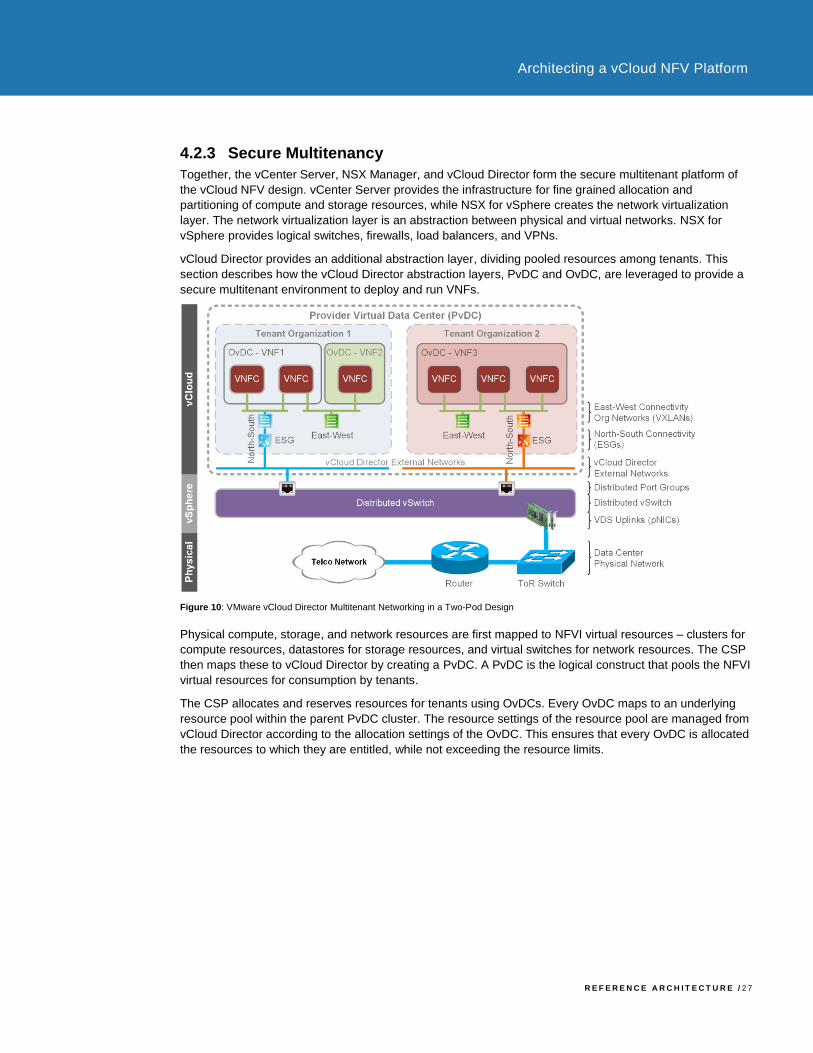
R E F E R E N C E A R C H I T E C T U R E / 2 7
Architecting a vCloud NFV Platform
4.2.3 Secure Multitenancy
Together, the vCenter Server, NSX Manager, and vCloud Director form the secure multitenant platform of
the vCloud NFV design. vCenter Server provides the infrastructure for fine grained allocation and
partitioning of compute and storage resources, while NSX for vSphere creates the network virtualization
layer. The network virtualization layer is an abstraction between physical and virtual networks. NSX for
vSphere provides logical switches, firewalls, load balancers, and VPNs.
vCloud Director provides an additional abstraction layer, dividing pooled resources among tenants. This
section describes how the vCloud Director abstraction layers, PvDC and OvDC, are leveraged to provide a
secure multitenant environment to deploy and run VNFs.
Figure 10: VMware vCloud Director Multitenant Networking in a Two-Pod Design
Physical compute, storage, and network resources are first mapped to NFVI virtual resources – clusters for
compute resources, datastores for storage resources, and virtual switches for network resources. The CSP
then maps these to vCloud Director by creating a PvDC. A PvDC is the logical construct that pools the NFVI
virtual resources for consumption by tenants.
The CSP allocates and reserves resources for tenants using OvDCs. Every OvDC maps to an underlying
resource pool within the parent PvDC cluster. The resource settings of the resource pool are managed from
vCloud Director according to the allocation settings of the OvDC. This ensures that every OvDC is allocated
the resources to which they are entitled, while not exceeding the resource limits.

R E F E R E N C E A R C H I T E C T U R E / 2 8
Architecting a vCloud NFV Platform
Figure 11: VMware vCloud Director Resource Partitioning in a Two-Pod Design
Tenant edge devices that are deployed from vCloud Director use a dedicated resource pool nested within
the PvDC resource pool. VNFs are deployed in a separate and dedicated resource pool nested within the
OvDC. This separation of edge devices and VNF workload resources prevents one from starving the other.
Separation of network access between NFVI tenants is important for supporting secure multitenancy on a
horizontally shared platform. vCloud Director integrates with vCenter Server and NSX for vSphere to
manage the creation and consumption of isolated Layer 2 networks. Connectivity to external networks, such
as the CSP MPLS network, must be manually set during the VNF onboarding process. Networks that are
internal to an NFVI tenant, or to a VNF instance, can be created using the vCloud Director user interface or
API. As described in the Virtual Networking Design Using VMware NSX Manager section of this document,
BGP routing, ESG firewall rules, and additional services, can be configured by the tenant administrator from
within the OvDC.
4.2.4 VNF Onboarding
A VNF is onboarded to a two-pod vCloud NFV design by following these steps: preparing the VNF for
consumption by vCloud Director, importing the VNF images, ensuring that the VNF is setup correctly in the
environment, storing it in a vCloud Director catalog, and deploying it by various means. The process can be
divided into CSP operations and tenant operations, as detailed in this section of the document.
vCloud Director supports importing VNFs as standard OVF/OVA packages. While multiple options are
available to create an OVF/OVA package, for best practices the VNF vendor must author the package in a
separate environment identical to the target vCloud NFV, to match its features and capabilities. To import a
VNF as a standard OVF package, follow these steps:
1. Create a vApp and add the VNFCs to it. Use of preconfigured, reusable virtual machine VNFC
templates simplifies the process of vApp creation.
2. East-West vApp VNF networks are created by provisioning organization networks. North-South
connectivity requires routed organization networks. Both networks are configured from within
vCloud Director.
3. VNF Components are connected to the networks and the VNF is validated on the NFVI platform.
4. The final vApp is captured as a vApp template and exported as an OVF package provided to the
CSP.
Ensuring that the resources needed for the VNF are available is not only integral, but central to the platform
design. This process is typically collaborative between the VNF vendor and the CSP. The VNF vendor
provides guidance based on lab testing, regarding the amount of virtual resources needed to support a
specific size or scale of telecommunications service. For example, a virtual Evolved Packet Core (vEPC) is
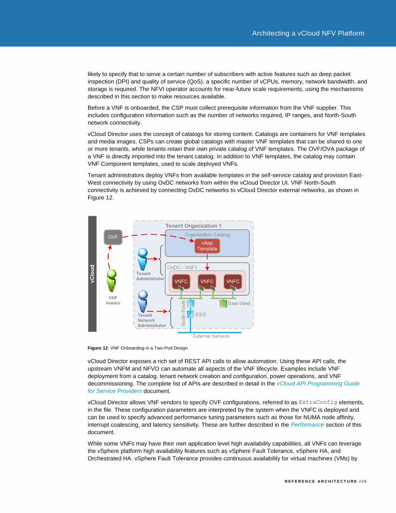
R E F E R E N C E A R C H I T E C T U R E / 2 9
Architecting a vCloud NFV Platform
likely to specify that to serve a certain number of subscribers with active features such as deep packet
inspection (DPI) and quality of service (QoS), a specific number of vCPUs, memory, network bandwidth, and
storage is required. The NFVI operator accounts for near-future scale requirements, using the mechanisms
described in this section to make resources available.
Before a VNF is onboarded, the CSP must collect prerequisite information from the VNF supplier. This
includes configuration information such as the number of networks required, IP ranges, and North-South
network connectivity.
vCloud Director uses the concept of catalogs for storing content. Catalogs are containers for VNF templates
and media images. CSPs can create global catalogs with master VNF templates that can be shared to one
or more tenants, while tenants retain their own private catalog of VNF templates. The OVF/OVA package of
a VNF is directly imported into the tenant catalog. In addition to VNF templates, the catalog may contain
VNF Component templates, used to scale deployed VNFs.
Tenant administrators deploy VNFs from available templates in the self-service catalog and provision East-
West connectivity by using OvDC networks from within the vCloud Director UI. VNF North-South
connectivity is achieved by connecting OvDC networks to vCloud Director external networks, as shown in
Figure 12.
Figure 12: VNF Onboarding in a Two-Pod Design
vCloud Director exposes a rich set of REST API calls to allow automation. Using these API calls, the
upstream VNFM and NFVO can automate all aspects of the VNF lifecycle. Examples include VNF
deployment from a catalog, tenant network creation and configuration, power operations, and VNF
decommissioning. The complete list of APIs are described in detail in the vCloud API Programming Guide
for Service Providers document.
vCloud Director allows VNF vendors to specify OVF configurations, referred to as ExtraConfig elements,
in the file. These configuration parameters are interpreted by the system when the VNFC is deployed and
can be used to specify advanced performance tuning parameters such as those for NUMA node affinity,
interrupt coalescing, and latency sensitivity. These are further described in the Performance section of this
document.
While some VNFs may have their own application level high availability capabilities, all VNFs can leverage
the vSphere platform high availability features such as vSphere Fault Tolerance, vSphere HA, and
Orchestrated HA. vSphere Fault Tolerance provides continuous availability for virtual machines (VMs) by
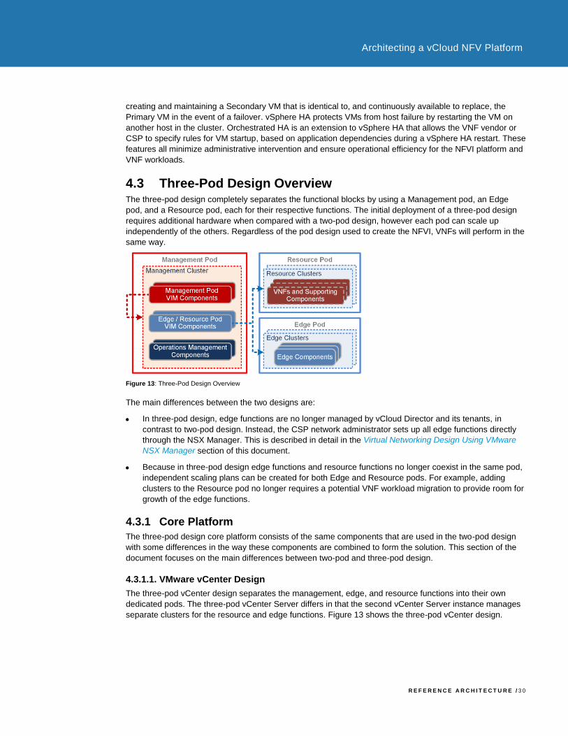
R E F E R E N C E A R C H I T E C T U R E / 3 0
Architecting a vCloud NFV Platform
creating and maintaining a Secondary VM that is identical to, and continuously available to replace, the
Primary VM in the event of a failover. vSphere HA protects VMs from host failure by restarting the VM on
another host in the cluster. Orchestrated HA is an extension to vSphere HA that allows the VNF vendor or
CSP to specify rules for VM startup, based on application dependencies during a vSphere HA restart. These
features all minimize administrative intervention and ensure operational efficiency for the NFVI platform and
VNF workloads.
4.3 Three-Pod Design Overview The three-pod design completely separates the functional blocks by using a Management pod, an Edge
pod, and a Resource pod, each for their respective functions. The initial deployment of a three-pod design
requires additional hardware when compared with a two-pod design, however each pod can scale up
independently of the others. Regardless of the pod design used to create the NFVI, VNFs will perform in the
same way.
Figure 13: Three-Pod Design Overview
The main differences between the two designs are:
• In three-pod design, edge functions are no longer managed by vCloud Director and its tenants, in
contrast to two-pod design. Instead, the CSP network administrator sets up all edge functions directly
through the NSX Manager. This is described in detail in the Virtual Networking Design Using VMware
NSX Manager section of this document.
• Because in three-pod design edge functions and resource functions no longer coexist in the same pod,
independent scaling plans can be created for both Edge and Resource pods. For example, adding
clusters to the Resource pod no longer requires a potential VNF workload migration to provide room for
growth of the edge functions.
4.3.1 Core Platform
The three-pod design core platform consists of the same components that are used in the two-pod design
with some differences in the way these components are combined to form the solution. This section of the
document focuses on the main differences between two-pod and three-pod design.
4.3.1.1. VMware vCenter Design
The three-pod vCenter design separates the management, edge, and resource functions into their own
dedicated pods. The three-pod vCenter Server differs in that the second vCenter Server instance manages
separate clusters for the resource and edge functions. Figure 13 shows the three-pod vCenter design.

R E F E R E N C E A R C H I T E C T U R E / 3 1
Architecting a vCloud NFV Platform
Figure 14: VMware vCenter Three-Pod Design
With three-pod design, each pod is implemented as a cluster. This enables the NFVI operator to specify
different cluster level configurations for the edge and resource clusters.
The Management pod of the three-pod design is almost identical to that of the two-pod design. The only
exception is the vCenter Server that manages two clusters, one for the Resource pod and one for the Edge
pod respectively, while the same vCenter Server in the two-pod design manages only the collapsed
Edge / Resource pod.
4.3.1.2. Virtual Networking Design Using VMware NSX Manager
Figure 14 shows the role of the NSX Manager in a three-pod design.
Figure 15: VMware NSX Manager in a Three-Pod Design
The second NSX Manager in the Management pod is associated with the vCenter Server that manages the
Edge pod. CSP network administrators use this instance of the NSX Manager to operate tenant network
services. Tenants must coordinate their connectivity needs with the administrator during VNF onboarding.
For VNF Components that require East-West connectivity, the CSP network administrator uses the same
NSX Manager to create VXLAN backed logical switches that are extended to vCloud Director as external
networks. Tenant administrators connect VNFs to these networks to create communication channels
between the VNF Components.

R E F E R E N C E A R C H I T E C T U R E / 3 2
Architecting a vCloud NFV Platform
For VNF Components that require North-South connectivity, logical switches are routed to the
telecommunications network through the edge services deployed in the Edge pod. A VXLAN transport zone
is created between the Resource pod and the Edge pod, which allows logical switches to seamlessly
interconnect the VNFs in the Resource pod to the edge networking services in the Edge pod. Figure 16
shows the design for Edge pod and Resource pod connectivity.
Figure 16: Virtual Networking Design for Edge Pod and Resource Pod Connectivity
CSPs manage compute and memory resources of edge devices by placing them in dedicated tenant
resources pools. These resource pools allow for fine grained resource partitioning, allocation, and
reservation to the tenant edge device, as described in Figure 18.
Different routing scenarios are detailed in the VNF Onboarding in Three-Pod Design section of this
document. These scenarios address connectivity between VNFCs inside of a VNF, connectivity between
different VNFs, and connectivity between VNFs and their management components.
Since CSP network administrators have direct access to NSX for vSphere, they can leverage advanced
edge services such as distributed logical routers (DLRs) to handle additional network functions including:
VXLAN to VLAN bridging, efficient routing between VNF networks across VNFCs and VNFs, distributed
firewalls, and redundant routing protocol using ECMP. The logical routing design is based on per VNF
requirements and should be decided as part of the onboarding process.
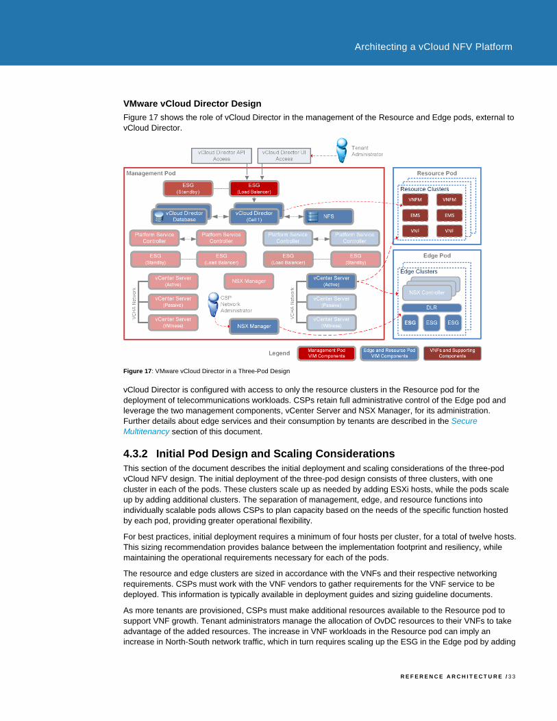
R E F E R E N C E A R C H I T E C T U R E / 3 3
Architecting a vCloud NFV Platform
VMware vCloud Director Design
Figure 17 shows the role of vCloud Director in the management of the Resource and Edge pods, external to
vCloud Director.
Figure 17: VMware vCloud Director in a Three-Pod Design
vCloud Director is configured with access to only the resource clusters in the Resource pod for the
deployment of telecommunications workloads. CSPs retain full administrative control of the Edge pod and
leverage the two management components, vCenter Server and NSX Manager, for its administration.
Further details about edge services and their consumption by tenants are described in the Secure
Multitenancy section of this document.
4.3.2 Initial Pod Design and Scaling Considerations
This section of the document describes the initial deployment and scaling considerations of the three-pod
vCloud NFV design. The initial deployment of the three-pod design consists of three clusters, with one
cluster in each of the pods. These clusters scale up as needed by adding ESXi hosts, while the pods scale
up by adding additional clusters. The separation of management, edge, and resource functions into
individually scalable pods allows CSPs to plan capacity based on the needs of the specific function hosted
by each pod, providing greater operational flexibility.
For best practices, initial deployment requires a minimum of four hosts per cluster, for a total of twelve hosts.
This sizing recommendation provides balance between the implementation footprint and resiliency, while
maintaining the operational requirements necessary for each of the pods.
The resource and edge clusters are sized in accordance with the VNFs and their respective networking
requirements. CSPs must work with the VNF vendors to gather requirements for the VNF service to be
deployed. This information is typically available in deployment guides and sizing guideline documents.
As more tenants are provisioned, CSPs must make additional resources available to the Resource pod to
support VNF growth. Tenant administrators manage the allocation of OvDC resources to their VNFs to take
advantage of the added resources. The increase in VNF workloads in the Resource pod can imply an
increase in North-South network traffic, which in turn requires scaling up the ESG in the Edge pod by adding
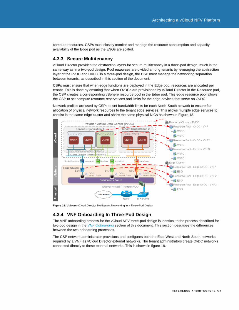
R E F E R E N C E A R C H I T E C T U R E / 3 4
Architecting a vCloud NFV Platform
compute resources. CSPs must closely monitor and manage the resource consumption and capacity
availability of the Edge pod as the ESGs are scaled.
4.3.3 Secure Multitenancy
vCloud Director provides the abstraction layers for secure multitenancy in a three-pod design, much in the
same way as in a two-pod design. Pool resources are divided among tenants by leveraging the abstraction
layer of the PvDC and OvDC. In a three-pod design, the CSP must manage the networking separation
between tenants, as described in this section of the document.
CSPs must ensure that when edge functions are deployed in the Edge pod, resources are allocated per
tenant. This is done by ensuring that when OvDCs are provisioned by vCloud Director in the Resource pod,
the CSP creates a corresponding vSphere resource pool in the Edge pod. This edge resource pool allows
the CSP to set compute resource reservations and limits for the edge devices that serve an OvDC.
Network profiles are used by CSPs to set bandwidth limits for each North-South network to ensure fair
allocation of physical network resources to the tenant edge services. This allows multiple edge services to
coexist in the same edge cluster and share the same physical NICs as shown in Figure 18.
Figure 18: VMware vCloud Director Multitenant Networking in a Three-Pod Design
4.3.4 VNF Onboarding In Three-Pod Design
The VNF onboarding process for the vCloud NFV three-pod design is identical to the process described for
two-pod design in the VNF Onboarding section of this document. This section describes the differences
between the two onboarding processes.
The CSP network administrator provisions and configures both the East-West and North-South networks
required by a VNF as vCloud Director external networks. The tenant administrators create OvDC networks
connected directly to these external networks. This is shown in figure 19.

R E F E R E N C E A R C H I T E C T U R E / 3 5
Architecting a vCloud NFV Platform
Figure 19: VNF Onboarding in a Three-Pod Design
These are the steps for VNF onboarding in a vCloud NFV three-pod design:
1. The OVF package of a VNF is imported directly into the vCloud Director catalog.
2. Tenant administrators deploy VNFs from the available templates in the self-service catalog, or from
the available VNF templates in the global CSP catalog.
3. Tenant administrators deploy VNFs and connect these to the appropriate networks created by the
CSP network administrator to complete the VNF network topology.
Figure 20 shows how various VNF networking scenarios may be implemented to build the VNF networks.
Figure 20: VNF Networking in a Three-Pod Design

R E F E R E N C E A R C H I T E C T U R E / 3 6
Architecting a vCloud NFV Platform
VNFs require management access to establish the necessary network connectivity, for example between a
VNFM deployed in the Resource pod and an NFVO deployed in the Management pod. Components in the
Management pod are connected to the management network VLAN. This VLAN is trunked to the hosts in
the Edge pod where the physical NICs are assigned as uplinks to a VDS. The CSP provisions a logical
switch connected to an NSX Edge instance to extend the management network to vCloud Director. The
NSX Edge instance performs the role of a VXLAN to VLAN bridge, to provide edge services such as NAT
and a stateful firewall for security.
Implementation of East-West connectivity between VNFCs in the same OvDC, and connectivity between
VNFs in two different OvDCs belonging to the same organization, is identical. This is because organization
networks are accessible by all OvDCs within the organization. Such organization networks are connected to
vCloud Director external networks mapped to logical switches and provisioned by the CSP.
The North-South network is also a vCloud Director external network mapped to a logical switch. It is
connected to the telecommunications network through an NSX for vSphere ESG. The ESG can be
configured with edge services such as NAT, VPN, and firewall, in addition to its role as a router.
The three-pod design offers all the cluster high availability capabilities described in the VNF Onboarding
section of this document, such as vSphere Fault Tolerance, vSphere HA, and Orchestrated HA.
4.3.5 Using Two-Pod or Three-Pod Design for vCloud NFV
Given the two design options available, a greenfield deployment will be faced with a choice regarding the
most appropriate vCloud NFV design to use. As an engineering decision, differences between the two
designs and their potential use cases must first be understood. This section of the document provides
considerations to guide CSPs in choosing between the two-pod and three-pod designs.
The vCloud NFV architecture ensures that key capabilities like secure multitenancy, integrated operational
management, and carrier grade readiness are untouched by the choice of pod design. Neither choice will
influence the ability of the NFV platform to support virtualized network services.
Two-pod design provides the VNF tenant with great flexibility in how to set up their virtual networking, both
internally to the VNFs, and with external networks. Tenants can set up network and security services with
minimal dependency on cloud networking administrators. This translates to a simplified VNF onboarding
experience and great autonomy for the VNF tenant. To some CSPs, the ability to provide VNF vendors with
a secure tenancy where the VNF can be configured and prepared to the tenant’s liking is beneficial. Other
CSPs will prefer to maintain control of all networking-related configurations, and may want to separate the
VNF tenant from its external networking capabilities.
Another difference between two-pod and three-pod design is the footprint required for deployment. Two-pod
design requires a smaller number of hosts, racks, and ToR switches than three-pod design. This means that
distributed deployments such as those used in micro data centers or telecommunications central offices,
where space and cooling is at a premium, may benefit from two-pod design. Some enterprise service use
cases, such as premise-based virtual Customer Premise Equipment (CPE), also benefit from the smaller
footprint of two-pod design. In these use cases, administrative boundaries can be made very clear by
mapping the collapsed Edge / Resource pod to a single rack. In use cases where space is ample and virtual
network functions perform a centralized role, maintaining the functional separation between the three pods
is beneficial.
Capacity planning and scale up operations are natural and straight forward in three-pod design. With this
design, each pod scales independent of the others. In two-pod design with both edge and resource
functions sharing the same pod, as VNFs are added, careful consideration must be taken of the resources
available to edge function operations. All the tools required for capacity planning and proactive resource
usage monitoring are provided with vCloud NFV, and tools to migrate VNFs to necessary resources are also
available.
As two-pod design facilitates greater autonomy to tenant operations, some advanced networking topologies

R E F E R E N C E A R C H I T E C T U R E / 3 7
Architecting a vCloud NFV Platform
will require the involvement of other functions and administrative domains. Depending on the type of
communications to be used in the NFV environment, this aspect must also be taken into consideration.
4.4 Operations Management The NFVI Operations Management components are a functional block in the Management pod. These
components are responsible for providing and extending full visibility to fault, configuration, accounting,
performance, and security (FCAPS) of the NFVI, and when needed the Virtual Network Functions (VNFs).
The VMware implementation of the vCloud NFV platform expands the capabilities of this functional block by
offering business continuity and disaster recovery capabilities. Disaster recovery is discussed in the
Business Continuity and Disaster Recovery section of this document.
For the vCloud NFV platform, the NFVI Operations Management tasks are delivered using the components
listed in Table 3. All components are deployed in the Management pod.
COM P O NE N T N AM E DE S C RI P TI ON
VMware vRealize Operations
Manager
VMware vRealize Operations Manager handles performance and
capacity management of the NFVI and VIM components. It is the
primary network operations center (NOC) NFVI management console.
VMware vRealize Log Insight
VMware vRealize Log Insight provides real-time log management and
log analysis with machine learning-based intelligent grouping, high-
performance search, and targeted troubleshooting across physical,
virtual, and cloud environments.
VMware vRealize Network
Insight
VMware vRealize Network Insight provides visibility and analytics into
the networking aspects of the NFVI. It monitors network performance
and availability across virtual and physical networks, provides visibility
into network communication between VNF Components, and extends
visibility into external network paths, Internet access, and VXLAN.
Table 3: NFVI Operations Management Components
4.4.1 Operations Workflow
Management of the NFV environment is driven by the three tools described in this section of the document:
vRealize Operations Manager, vRealize Log Insight, and vRealize Network Insight. The network operations
center (NOC) primarily interacts with vRealize Operations Manager as a single pane of glass, while using
the other tools for issue isolation, remediation, and planning.
The vRealize Operations user interface can be configured in various ways, however the main pane informs
the NOC personnel about three categories:
• Health. The current health of the system is displayed in this tab. Red alerts in this tab indicate that an
immediate issue is taking place.
• Risk. Future issues, based on deep machine learning and analytics, are displayed in this tab. Risks
indicate future performance or capacity problems and can become health issues. Proactively resolving
risks is the best approach to maintaining high quality services.
• Efficiency. This area indicates optimization opportunities based on the way the platform is used. If the
operator follows these recommendations, NFVI resources used in a wasteful way, or suboptimally
configured, can be recovered and the platform efficiency will increase.

R E F E R E N C E A R C H I T E C T U R E / 3 8
Architecting a vCloud NFV Platform
The NFVI operator first focuses on maintaining the healthy state of the environment. When a vRealize
Operations Manager Health Badge reports red, a critical issue is raised and an indication of the cause is
provided. To resolve the issue the operator is presented with further detail in the vRealize Operations
graphical user interface. These details are collected using vRealize Log Insight. The operator can correlate
network information, using vRealize Network Insight to speed up issue resolution. In combination, these
three tools ensure that all layers of the NFVI environment are monitored, and that issues are quickly isolated
and remediated.
vRealize Operations Manager monitors performance and capacity by collecting information exposed by the
devices it monitors. NFVI performance information, such as the number of hosts, virtual machines, physical
cores, and vCPU used, are examples of the compute metrics monitored. vRealize Operations Manager also
collects information about networking components, including interface utilization, packet drop rate, observed
throughput, and storage information as read and write performance, usage rate, and total capacity. The
performance and capacity data collected provide a holistic system view that can be used to manually
address issues and perform capacity planning. Alternatively, Distributed Resource Scheduler (DRS) can be
used to automatically balance VNF Components based on performance needs and capacity availability,
eliminating resource contention that might otherwise occur.
In VMware vCloud NFV 2.0, future resource contention is evaluated based on continuous monitoring.
Coupled with vRealize Operations Manager dynamic thresholds, which understand the behavior of VNFs
throughout the day, calculations are run to create a band describing normal operations for each metric and
object combination. The band includes an upper and lower boundary for each metric associated with an
object, and is tailored specifically to the individual VNF Component, providing data about the amount of
resources the component requires throughout the day. Together with an understanding of the size of the
NFVI hosts, and their aggregated resources, the operator can predict where contention will occur and can
balance the VNFs accordingly. Network utilization is one of the new data points added to the DRS
considerations in VMware vCloud NFV 2.0, in addition to storage, CPU, and memory.
Network DRS is fundamental to the multitenancy characteristic of the platform as described. Using Network
I/O Control (NIOC) it is possible to set a reservation for a VNF Component in terms of network bandwidth
and have DRS consider the reservation in resource placement. This means that when network capacity
planning is performed for tenants, the operator can rely on DRS to ensure that tenants are not consuming
other tenants’ network capacity.
Figure 21 shows the vCloud NFV Operations Management design. In the following sections, we discuss the
design of each individual operations management component.
Figure 21: VMware vCloud NFV Operations Management Design
R E F E R E N C E A R C H I T E C T U R E / 3 9
Architecting a vCloud NFV Platform
4.4.2 VMware vRealize Operations Manager
The virtual infrastructure relies on a monitoring solution able to collect data regarding its health, capacity,
availability, and performance. vRealize Operations Manager provides a robust and integrated monitoring
platform that sits at the center of the NFV environment. As described in the Operations Workflow section of
this document, it serves as the single pane of glass into the NFV environment.
vRealize Operations Manager is installed in the Management pod in both two-pod and three-pod designs.
As it collects more data over time, it is possible that additional storage capacity will be required. Adding
more hosts to the management cluster, or simply more storage, is sufficient to address the growing storage
needs of vRealize Operations Manager.
Since vRealize Operations Manager is the central management component in the vCloud NFV platform, its
availability to the operator is essential. vRealize Operations Manager supports High Availability (HA). HA
creates a master replica for the vRealize Operations Manager master node and protects the analytics
cluster against the loss of a node. With HA, data stored on the master node is always completely backed up
on the master replica node. To enable HA, at least one other data node must be deployed in addition to the
master node. Further information is provided in the vRealize Operations Manager vApp Deployment and
Configuration Guide.
VMware vRealize Operations Management Pack
VMware vRealize Operations Manager collects structure data from various sources, including gathering data
from adapters connected to source servers. For this mechanism to work, vRealize Operations Manager is
configured to communicate with source servers using an authorized user account. If the user account has
limited access to objects in the source server, it sees only the data for which the account has permissions.
At a minimum, the user account must have read privileges across the objects from which it will collect data.
A collection of management packs is available on the VMware Cloud Management Marketplace.
To minimize traffic between the vCenter Server and the vRealize Operations Manager, the vCenter Server
Adapter is installed with a five minute collection interval.
VNF vendors can create plug-ins, which are interfaces between vRealize Operations Manager and external
components that require management. Plug-in development requires an understanding of the vRealize
Operations Manager inventory model, the management functions that plug-ins implement. These include
auto-discovery and monitoring. Additional information is available in the Endpoint Operations Management
Agent Plug-in Development Kit document.
VMware vRealize Operations Manager Logging
Audit logs are used to track configuration changes performed by authenticated users to see who initiated a
change or scheduled a job that performed the change. All audit logs are forwarded to vRealize Log Insight.
VMware vRealize Operations Manager Alerts
When alerts are generated in vRealize Operations Manager, they appear in the alert details and object
details windows. Alerts can also be configured to be sent to other applications using one or more outbound
alert options.
To configure notification options, the operator must specify which alerts are sent out with the standard email,
REST, SNMP traps, and log file outbound alert plug-ins. The decision to use a specific alerting method is
implementation specific and is typically driven by the external monitoring and management tools available.
R E F E R E N C E A R C H I T E C T U R E / 4 0
Architecting a vCloud NFV Platform
4.4.3 VMware vRealize Log Insight
VMware vRealize Log Insight is used to collect log data from ESXi hosts. It is also used to connect to
vCenter Servers to collect server events, tasks, and alarm data. vRealize Log Insight integrates with
vRealize Operations Manager to send notification events. Since vRealize Log Insight collects real-time
unstructured data, all elements in the NFV environment can be configured to send their log data to it. This
log aggregation provides a single log collector for the NFV environment.
VMware vRealize Log Insight is deployed in the Management pod using a single cluster configuration, which
consists of a minimum of three nodes leveraging the Log Insight Integrated Load Balancer (ILB). A single
log message is only present in one location within the cluster at a time. The cluster remains up and available
to ingest data and serve queries during any temporary unavailability of a single node.
Data is collected using the syslog protocol or an API. All NSX Manager syslog information, distributed
firewall logs, and NSX Edge Services Gateway syslog information is sent to vRealize Log Insight. Each
vCloud Director cell produces logs that are sent to vRealize Log Insight as well.
Additional vCloud Director troubleshooting and API access logs are stored locally on the vCloud Director
cells. These logs can be forwarded by creating an additional logger that can send diagnostics logs to
vRealize Log Insight. Detailed information is provided in the Knowledge Base article Enabling Centralized
Logging in VMware vCloud Director (2004564).
VMware vRealize Log Insight Content Pack
vRealize Log Insight gathers log events from multiple sources, and through special content packs delivers
solution specific dashboards to perform log analytics, using redefined alerts. For additional information about
vRealize Log Insight solutions, see the VMware vCloud Management Marketplace.
VMware vRealize Log Insight Archiving
Archiving is primarily a long term retention tool. The process copies raw data to an external NFS storage
location. Archives are much smaller than indexes, but require indexing if they are loaded back into the
vRealize Log Insight system. For additional information about vRealize Log Insight archiving, see the
VMware vRealize Log Insight Information page.
4.4.4 VMware vRealize Network Insight
vRealize Network Insight is installed in the Management pod in both two-pod and three-pod designs. In an
ideal situation, vRealize Network Insight is configured to monitor all networking-related components in the
NFVI. Naturally, vRealize Network Insight can connect to the vCloud NFV components relating to
networking: vSphere and NSX for vSphere. It can also be configured to monitor a myriad of physical devices
such as Dell switches, Cisco Nexus and Catalyst switches, and Arista, Juniper Networks, Hewlett Packard
Enterprise, Brocade, and Palo Alto Networks switches.
The vRealize Network Insight architecture consists of a platform VM, a proxy VM, and data sources. The
role of the platform VM within the architecture is to perform analytics, storage, and to provide a user
interface into the data. The proxy VM, or the collector, collects data from sources using various protocols
such as HTTPS, SSH, CLI, and SNMP, depending on the source and the configuration. A variety of data
sources are supported, including VMware vCenter, NSX, firewalls, and various switch vendors. To provide a
complete overview of the NFV environment, vRealize Network Insight is connected to the vCenter Server
that is used to operate the edge and resource clusters as is shown in Figure 21.

R E F E R E N C E A R C H I T E C T U R E / 4 1
Architecting a vCloud NFV Platform
4.4.5 Business Continuity and Disaster Recovery
Business continuity and disaster recovery solutions are an integral part of the vCloud NFV platform. To
achieve a robust solution, the following three components are used.
COM P O NE N T N AM E DE S C RI P TI ON
VMware vSphere Replication
VMware vSphere Replication is a hypervisor-based asynchronous
replication solution that provides granular replication and recovery of
management components.
VMware Site Recovery
Manager
VMware Site Recovery Manager is a disaster recovery management
and orchestration engine for providing predictable failover of
management components.
VMware vSphere Data
Protection
VMware vSphere Data Protection provides data protection by
performing backup and recovery of management components.
Table 4: NFVI Business Continuity and Disaster Recovery Components
The methods for using these three business continuity and disaster recovery tools to ensure healthy
operations in the NFV environment are described in the following sections of the document. While a
multi-site design will be the subject of a future document, this reference architecture provides an overview of
the business continuity capabilities built into vCloud NFV.
4.4.5.1. VMware vSphere Replication
vSphere Replication is the technology used to replicate virtual machine data between data center objects
within a single site or across sites. It fully supports vSAN. vSphere Replication is deployed as an appliance
within the management cluster to provide a Recovery Point Objective (RPO) of five minutes to 24 hours.
The two most important aspects to be considered when designing or executing a disaster recovery plan are
RPO and Recovery Time Objective (RTO). RPO is the duration of acceptable data loss. It is fulfilled by the
replication technology. RTO is a target duration with an attached service-level agreement, during which the
business process must be restored. It includes the time for the recovery and service readiness, in a state for
business to operate as usual.
vSphere Replication provides the ability to set the RPO, however RTO is application dependent.
4.4.5.2. VMware Site Recovery Manager
Site Recovery Manager provides a solution for automating the recovery and execution of a disaster recovery
plan, in the event of a disaster in a data center. When a catastrophe occurs, components in the
Management pod must be available to recover and continue the healthy operations of the NFV-based
services.
To ensure robust business continuity and disaster recovery, network connectivity between the protected and
recovery sites is required, with enough bandwidth capacity to replicate the management components using
vSphere Replication. Each site must have an instance of vCenter Server that governs the Management pod
and its ESXi hosts, and a Site Recovery Manager server and vSphere Replication appliance to orchestrate
the disaster recovery workflows and replicate content across the sites. The protected site provides business
critical services, while the recovery site is an alternative infrastructure on which services are recovered in
the event of a disaster.

R E F E R E N C E A R C H I T E C T U R E / 4 2
Architecting a vCloud NFV Platform
Networking Considerations
Moving a service from one site to another represents a networking challenge in terms of maintaining IP
addressing, security policies, and bandwidth ensuring ample network capacity. Some of these challenges,
such as IP addressing, are managed by using NSX for vSphere.
Distributed Resource Scheduler Considerations
Some management components for the vCloud NFV platform such as NSX for vSphere, Edge Services
Gateway, PSCs, vCloud Director cells, vRealize Operations Manager, and vRealize Log Insight have
specific affinity or anti-affinity rules configured for availability. When protected management components are
recovered at a recovery site, DRS rules, reservations, and limits are not carried over as part of the recovery
plan. However, it is possible to manually configure rules, reservations, and limits on placeholder virtual
machines at the recovery site, during the platform build.
Inventory Mappings
Elements in the vCenter Server inventory list can be mapped from the protected site to their vCenter Server
inventory counterparts on the recovery site. Such elements include virtual machine folders, clusters or
resource pools, and networks. All items within a single data center on the protected site must map to a
single data center on the recovery site.
These inventory mapping details are used across both the protected and recovery sites:
• Resource mapping maps cluster objects on the protected site to cluster objects on the recovery site.
• Folder mapping maps the folder structures like data centers or virtual machine folders on the protected
site to folder structures on the recovery site.
• Network mapping maps the management networks on the protected site to management networks on
the recovery site.
VNF Recovery Considerations
Every vendor must provide a specific strategy for disaster recovery for any VNF managed directly by the
VNF Managers.
Protection Groups
A protection group is a group of management components at the protected site that can fail over together to
the recovery site during testing and recovery. All protected management components are placed within a
single protection group.
Recovery Plans
Recovery plans are the run books associated with a disaster recovery scenario. A recovery plan determines
which management components are started, what needs to be powered down, which scripts to run, the
startup order, and the overall automated execution of the failover.
A complete site failure is the only scenario that invokes a disaster recovery. There is no requirement for
recovery plans to handle planned migrations or to move a single failed application within the management
cluster. A single recovery plan is created for the automated failover of the primary site, and the placement of
management components into priority groups ensures the correct startup order.
The recovery of the resource cluster, edge cluster, vCenter Server, and NSX Manager are required to
maintain management capabilities where additional physical data centers are managed within the site.

R E F E R E N C E A R C H I T E C T U R E / 4 3
Architecting a vCloud NFV Platform
4.4.6 VMware vSphere Data Protection
vSphere Data Protection is a disk-based backup and recovery solution that is fully integrated with vCenter
Server and vSphere Web Client to enable centralized management of backup and restore tasks, while
storing backups in deduplicated backup storage. Managing the backup and restore tasks is accomplished
through the vSphere Data Protection UI, which is an add on plug-in to the vSphere Web Client.
vSphere Data Protection creates image-level backups, which are integrated with the VMware vSphere®
vStorage APIs for Data Protection, a feature set within VMware vSphere used to offload the backup
processing overhead from a virtual machine to the VDP appliance. The VDP appliance communicates with
the vCenter Server to make a snapshot of the .vmdk files in a virtual machine. Deduplication takes place
within the appliance, using a patented variable length deduplication technology.
vSphere Data Protection is distributed in a prepackaged OVA file. The vSphere Data Protection appliance is
responsible for the backup and restore of the management components residing within the management
cluster. vSphere Data Protection is configured so the appliance backs up the data to a deduplicated backup
datastore, which is different from the datastore hosting management components.
vSphere Data Protection protects the management cluster through the vCenter Server management layer.
Connectivity through vCenter Server provides vSphere Data Protection with visibility to all ESXi servers in
the management clusters, and therefore to all management components that must be backed up.
The initial configuration of the vSphere Data Protection appliance should be set to 6 terabytes. The
additional disk space required above the usable capacity of the appliance is for creating and managing
checkpoints. Backups can be configured to protect required components from the management cluster. In a
disaster recovery or data loss event, the protected components can be restored to resume normal services
based on the RPO. The target location must meet the minimum performance requirements for mitigation.
RPO. vSphere Data Protection can perform daily backups at scheduled intervals for required components
within the management cluster. The RPO value and the backup start time must be set as required based on
the business needs. It is recommended to schedule backups during off-peak business hours.
Retention Policies. Retention policies are the properties of a backup job. It is important to group
management components in a backup job by business priorities and by the retention requirements set
based on the business needs.
Monitoring. CPU, memory, network, disk performance, and the capacity of the vSphere Data Protection
appliance are monitored by vRealize Operations Manager, with syslog events sent to vRealize Log Insight.
Capacity can be viewed through vSphere Data Protection reports.
For backup of vCenter components and NSX Manager data, respective inbuilt backup mechanisms can be
leveraged.

R E F E R E N C E A R C H I T E C T U R E / 4 4
Architecting a vCloud NFV Platform
4.5 Carrier Grade Carrier grade attributes are injected into every layer of the vCloud NFV platform. High availability, a core
pillar in the architecture and a crucial requirement in every CSP network, spans the entire platform. When
discussing management components of the platform, the various redundancy mechanisms that allow them
to be highly available are highlighted, as are details of the ways in which networking elements can be made
highly redundant with the use of routing protocols and NIC teaming. The NFVI virtualization layer also
provides mechanisms to the Virtual Network Functions to enhance and improve their availability. These
include vSphere Fault Tolerance (FT), High Availability (HA), and Orchestrated HA.
Even though tuning the vCloud NFV platform for performance spans the NFVI, VNFs, and VIM, since it is
applicable to specific VNFs, performance architecture recommendations are grouped in this section.
4.5.1 Performance
ETSI classifies NFV workloads into three categories: management, control, and data plane. Based on
experience deploying vCloud NFV in various CSP networks, data plane workloads are further divided into
intensive workloads, and workloads that behave as management and control plane workloads. The latter
class of data plane workloads have been proven to function well on the vCloud NFV platform, as has been
described in this reference architecture. Further information regarding these workloads is provided in the
VNF Performance in Distributed Deployments section of this document. For data plane intensive VNFs
hosted on the vCloud NFV platform, specific design considerations are provided in the following section of
this document.
4.5.1.1. Data Plane Intensive Design Framework
Two parties are involved in the successful deployment and operations of a data plane intensive VNF: the
VNF vendor and the NFVI operator. Both parties must be able to understand the performance requirements
of the VNF, and share an understanding of the VNF design. They must also be willing to tune the entire
stack from the physical layer to the VNF itself, for the demands data plane intensive workloads place on the
system. The responsibilities of the two parties are described as follows:
Virtual Network Function Design and Configuration. The vendor supplying the VNF is expected to tune
the performance of the VNF components and optimize their software. Data plane intensive workloads
benefit from the use of a Data Plane Development Kit (DPDK) to speed up VNFC packet processing and
optimize the handling of packets off loading to the virtual NIC. Use of the VMware VMXNET3 paravirtualized
network interface card (NIC) is a best practice VNF design for performance demanding VNFs. VMXNET3 is
the most advanced virtual NIC on the VMware platform and has been contributed to the Linux community,
making it ubiquitous in many Linux distributions.
Once the VNF is created by its supplier, there are several VNFC level configurations that are essential to
these types of workloads. Dedicated resource allocation, for the VNFC and the networking-related
processes associated with it, can be configured and guaranteed through the use of two main parameters:
Latency Sensitivity and System Contexts. Both parameters are discussed in detail in a separate white
paper.
Another aspect essential to the performance of a data plane intensive VNF is the number of virtual CPUs
required by the VNFC. Modern multiprocessor server architecture is based on a grouping of resources,
including memory and PCIe cards, into Non-Uniform Memory Access (NUMA) nodes. Resource usage
within a NUMA node is fast and efficient. However, when NUMA boundaries are crossed, due to the
physical nature of the QPI bridge between the two nodes, speed is reduced and latency increases. VNFCs
that participate in the data plane path are advised to contain the virtual CPU, memory, and physical NIC
associated with them to a single NUMA node for optimal performance.

R E F E R E N C E A R C H I T E C T U R E / 4 5
Architecting a vCloud NFV Platform
NFVI Design Considerations. Once the VNFs are tuned for performance, the underlying physical and
virtual infrastructure must be prepared with data plane intensive workloads in mind. The modular nature of
the vCloud NFV platform facilitates the construction of an NFVI aimed at data plane intensive workloads,
while still using the same VIM and FCAPS components used elsewhere in the architecture. The same VIM
and FCAPS components are employed for the building of a data plane intensive NFVI and in the governing
of management and control plane VNFs.
Data plane intensive VNFs tend to serve a central role in a CSP network: as a Packet Gateway in a mobile
core deployment, a Provider Edge router (PE) in an MPLS network, or a media gateway in an IMS
network. As a result, these VNFs are positioned in a centralized location in the CSP network: the data
center. With their crucial role, these VNFs are typically static and are used by the central organization to
offer services to a large customer base. For example, a virtualized Packet Gateway in a mobile core network
will serve a large geographical region as the central termination point for subscriber connections. Once the
VNF is deployed, it is likely to remain active for a long duration, baring any NFVI life cycle activities such as
upgrades or other maintenance.
This aggregation role translates into a certain sizing requirement. The VNFs must serve many customers,
which is the reason for their data plane intensive nature. Such VNFs include many components to allow
them to be scaled and managed. These components include at a minimum an OAM function, packet
processing functions, VNF-specific load balancing, and often log collection and monitoring. Individual
components can also require significant resources to provide large scale services.
The central position of these VNFs, their sizeable scale, and their static nature, all suggest that dedicated
resources are required to achieve their expected performance goals. These dedicated resources begin with
hosts using powerful servers with high performing network interface cards. The servers are grouped
together into a cluster that is dedicated to data plane intensive workloads. Using the same constructs
introduced earlier in this document, the data plane intensive cluster is consumed by vCloud Director and is
made into a PvDC. VNFs are then onboarded into the vCloud Director catalog for deployment.
To be able to benefit from virtual machine specific configuration such as Latency Sensitivity, the allocation
model configured for use by tenants in the data plane intensive workload OvDC is Reservation Pool. The
Reservation Pool allocation model allows VNFs to be configured with the CPU reservation set to maximum,
removing any CPU usage limits. The same applies to the memory reservation and limit. Both configurations
are prerequisites to using the Latency Sensitivity feature, which is the prerequisite for using the System
Contexts feature.
NUMA affinity is ensured by combining VNFC specific configuration and the distributed resource scheduler,
VMware vSphere® Distributed Resource SchedulerTM (vSphere DRS). The NUMA affinity parameter should
be configured in the Virtual Machine Advanced Parameters. Then, with the use of VM anti-affinity rules,
vSphere DRS will place the virtual machines into an empty NUMA node.
With the architecture provided in this section, data plane intensive workloads are ensured the resources
they require, to benefit from platform modularity while meeting carrier grade performance requirements.
Specific configuration and VNF design guidelines are detailed in a performance white paper on the subject.
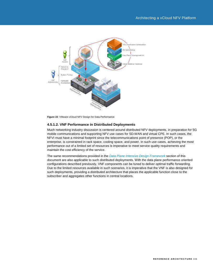
R E F E R E N C E A R C H I T E C T U R E / 4 6
Architecting a vCloud NFV Platform
Figure 22: VMware vCloud NFV Design for Data Performance
4.5.1.2. VNF Performance in Distributed Deployments
Much networking industry discussion is centered around distributed NFV deployments, in preparation for 5G
mobile communications and supporting NFV use cases for SD-WAN and virtual CPE. In such cases, the
NFVI must have a minimal footprint since the telecommunications point of presence (POP), or the
enterprise, is constrained in rack space, cooling space, and power. In such use cases, achieving the most
performance out of a limited set of resources is imperative to meet service quality requirements and
maintain the cost efficiency of the service.
The same recommendations provided in the Data Plane Intensive Design Framework section of this
document are also applicable to such distributed deployments. With the data plane performance oriented
configurations described previously, VNF components can be tuned to deliver optimal traffic forwarding.
Due to the limited resources available in such scenarios, it is imperative that the VNF is also designed for
such deployments, providing a distributed architecture that places the applicable function close to the
subscriber and aggregates other functions in central locations.

R E F E R E N C E A R C H I T E C T U R E / 4 7
Architecting a vCloud NFV Platform
Authors and Contributors
The following authors co-wrote this paper:
• Indranil Bal, Solution Consultant, NFV Solutions Engineering, VMware
• Pradip Kadam, Solution Consultant, NFV Solutions Engineering, VMware
• Jambi Ganbar, Technical Solutions Manager, NFV Solutions Engineering, VMware
Many thanks for contributions from:
• Danny Lin, Senior Director, NFV Solutions Engineering, VMware
• Michelle Han, Director, Solutions Testing and Validation, NFV Solutions Engineering, VMware
• Andrea Li, Lead Solutions Test Architect, NFV Solutions Engineering, VMware
• Jason Sauviac, Lead Solutions Architect, NFV Solutions Engineering, VMware
• Suresh Babu Nekkalapudi, Solutions Architect, NFV Solutions Engineering, VMware
• Ramkumar Venketaramani, Director PLM, Telco NFV group, VMware
• Sumit Verdi, NFV Lighthouse Solutions Director, Telco NFV group, VMware
• Frank Escaros-Buechsel, Solutions Architect, NFV, VMware
• Christian Hasner, Solutions Architect, NFV, VMware
• Neil Moore, Staff Solutions Architect, NFV, VMware
• Henrik Oberg, NFV Specialist, VMware
• Mauricio Valdueza, NFV Strategist, VMware

VMware, Inc. 3401 Hillview Avenue Palo Alto CA 94304 USA Tel 877-486-9273 Fax 650-427-5001 www.vmware.com
Copyright © 2017 VMware, Inc. All rights reserved. This product is protected by U.S. and international copyright and intellectual property laws. VMware products are covered by one or more patents listed at http://www.vmware.com/go/patents.
VMware is a registered trademark or trademark of VMware, Inc. in the United States and/or other jurisdictions. All other marks and names mentioned herein may be trademarks of their respective companies.