Architecting a Hybrid Mobility Strategy with the VMware ... · 16.2 Cisco vPC over DWDM and Dark...
38
1 | VMware vCloud ® Architecture Toolkit™ for Service Providers VMware vCloud ® Architecture Toolkit™ for Service Providers Architecting a Hybrid Mobility Strategy with the VMware Cloud Provider™ Program Version 2.9 January 2018 Martin Hosken
Transcript of Architecting a Hybrid Mobility Strategy with the VMware ... · 16.2 Cisco vPC over DWDM and Dark...
1 | VMware vCloud® Architecture Toolkit™ for Service Providers
VMware vCloud® Architecture Toolkit™ for Service Providers
Architecting a Hybrid Mobility Strategy with the VMware Cloud Provider™ Program
Version 2.9
January 2018
Martin Hosken
Architecting a Hybrid Mobility Strategy with the VMware Cloud Provider Program
2 | VMware vCloud® Architecture Toolkit™ for Service Providers
© 2018 VMware, Inc. All rights reserved. This product is protected by U.S. and international copyright and intellectual property laws. This product is covered by one or more patents listed at http://www.vmware.com/download/patents.html.
VMware is a registered trademark or trademark of VMware, Inc. in the United States and/or other jurisdictions. All other marks and names mentioned herein may be trademarks of their respective companies.
VMware, Inc. 3401 Hillview Ave Palo Alto, CA 94304 www.vmware.com

Architecting a Hybrid Mobility Strategy with the VMware Cloud Provider Program
3 | VMware vCloud® Architecture Toolkit™ for Service Providers
Contents
Introduction ............................................................................................. 5
Target Audience ...................................................................................... 6
Service Definition Overview .................................................................... 6
Architectural Overview ............................................................................ 8
Customer Business Case ........................................................................ 9
Use Case Scenario ................................................................................. 9
Conceptual Overview ............................................................................ 10
Designing the WAN Environment .......................................................... 13
Evaluation of WAN Platforms ................................................................ 16
9.1 Dark Fibre ......................................................................................................................... 16
9.2 Wavelength Division Multiplexing (DWDM and CWDM) ................................................... 17
9.3 SONET/SDH ..................................................................................................................... 18
9.4 Multiprotocol Label Switching (MPLS) .............................................................................. 19
Deploying Stretched VLANs/LAN Extensions ....................................... 21
10.1 Stretched VLAN/LAN Extension Technical Requirements .......................................... 24
WAN Interconnect High Availability ....................................................... 25
Secure Communication ......................................................................... 26
WAN Considerations Summary ............................................................ 26
Long-Distance Networking Summary .................................................... 27
VMware Requirements for Long-Distance vSphere vMotion ................ 28
15.1 vSphere Virtual Networking ......................................................................................... 30
15.2 vCenter Server and Platform Services Controller Design ........................................... 31
Workload Mobility Implementation Example ......................................... 33
16.1 Technology Overview .................................................................................................. 34
16.2 Cisco vPC over DWDM and Dark Fibre ....................................................................... 35
16.3 OTV over DWDM and Dark Fibre ................................................................................ 36
16.4 Cisco LISP Configuration Overview ............................................................................. 37
Solution Validation ................................................................................ 38

Architecting a Hybrid Mobility Strategy with the VMware Cloud Provider Program
4 | VMware vCloud® Architecture Toolkit™ for Service Providers
List of Figures
Figure 1. vRealize Automation ...................................................................................................................... 6
Figure 2. Long-Distance vSphere vMotion and Workload Mobility Logical Design ...................................... 8
Figure 3. Determining WAN Infrastructure Factors ..................................................................................... 13
Figure 4. Dark Fibre .................................................................................................................................... 16
Figure 5. Wave Division Multiplexing (DWDM and CWDM) ....................................................................... 17
Figure 6. SONET/SDH ................................................................................................................................ 18
Figure 7. Multiprotocol Label Switching (MPLS) ......................................................................................... 19
Figure 8. Stretched VLANs ......................................................................................................................... 21
Figure 9. Stretched VLANs over Dark Fibre ............................................................................................... 22
Figure 10. Stretched VLANs over Multiprotocol Label Switching (MPLS) .................................................. 23
Figure 11. Stretched VLANs over L2TP Version 3 ..................................................................................... 23
Figure 12. vSphere vMotion Process .......................................................................................................... 28
Figure 13. ESXi Clusters and Long Distance vSphere vMotion ................................................................. 29
Figure 14. vSphere Distributed Switch – Cross-Data Center Architecture ................................................. 31
Figure 15. Sample Platform Services Controller Design ............................................................................ 32
Figure 16. Use Case Logical Architecture .................................................................................................. 33
Figure 17. Architecture Overview ................................................................................................................ 34
Figure 18. Cisco vPC Domain ..................................................................................................................... 35
Figure 19. OTV Deployment over DWDM and Dark Fibre .......................................................................... 36

Architecting a Hybrid Mobility Strategy with the VMware Cloud Provider Program
5 | VMware vCloud® Architecture Toolkit™ for Service Providers
Introduction Many different approaches to architecting a VMware based hybrid cloud exist depending on the specific use case requirements and technologies employed, but the end goal is always the same. That is, a hybrid cloud is a cloud computing environment in which an organization provides and manages some resources in-house and has others provided externally.
VMware vSphere® 6 brings new enhancements to VMware vSphere vMotion®, giving businesses new and more flexible workload mobility options and new hybrid cloud architecture options. The newly enhanced vSphere vMotion capabilities of migrating workloads long distances and across geographic boundaries provide significant improvements for workload mobility use cases, enabling the ability to migrate workloads both on-premises and off-premises.
This newly enhanced workload mobility makes the notion of the hybrid cloud even more attractive to small and large businesses. The possibilities for disaster recovery, disaster avoidance, and distributed application architectures are numerous. What if there is a hurricane coming? Use vSphere vMotion to migrate to another data center 200 km away. What if your on-premises data center runs out of capacity or needs to temporarily burst into another facility? Free up some capacity locally by using vSphere vMotion to migrate virtual machines elsewhere by obtaining capacity on-demand from a VMware Cloud Provider™. With vSphere 6 long distance vSphere vMotion technology, workloads are more portable, more agile, and less tied to your physical data center than ever before.
Architecting a Hybrid Mobility Strategy with the VMware Cloud Provider Program
6 | VMware vCloud® Architecture Toolkit™ for Service Providers
Target Audience This document is targeted towards architects, engineers, application owners, and business leaders involved in the key decision making process and anyone else interested in guidance on designing a live workload mobility solution on VMware technologies.
While the design outlined in his paper is targeted toward a medium or large customer with enterprise application workloads, this type of solution can also be leveraged by smaller environments.
Service Definition Overview A hybrid cloud incorporates a combination of cloud instances and can include private, external, or public resources.
A business of any size with an existing private cloud can choose or be required to provide and manage public or external cloud resources in a secure and scalable way. The connectivity between different cloud instances that enables data and application portability is defined as the hybrid cloud solution.
A hybrid cloud is not made up of only two separate environments that are isolated from one another. The two environments must also have reliable high-speed connectivity with each other through the use of a data center interconnect.
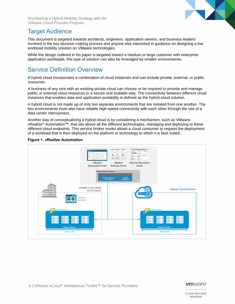
Another way of conceptualizing a hybrid cloud is by considering a mechanism, such as VMware vRealize® Automation™, that sits above all the different technologies, managing and deploying to these different cloud endpoints. This service broker model allows a cloud consumer to request the deployment of a workload that is then deployed on the platform or technology to which it is best suited.
Figure 1. vRealize Automation
Cloud Automation Platform
vRealize Automation Components
Platform Management
vRealize Automation Portal
vRealize Business Portal
vRealize Operations Portal
vSphere Cluster
vSphere DRS
vSphere Cluster
vSphere DRS
vCenter Server vCenter Server
VMware Cloud Provider
vRealize Operations
HYBRID CUSTOMER
On-Premises
Architecting a Hybrid Mobility Strategy with the VMware Cloud Provider Program
7 | VMware vCloud® Architecture Toolkit™ for Service Providers
Key business drivers and other reasons that customers consider deploying hybrid clouds include the following:
• Reduced total cost of ownership (TCO)
• Lower capital expenditures (CAPEX) when trying new markets
• Business agility
• Provides a clear use case for public cloud computing
• A hybrid cloud model is a valuable approach to architecture
• Ability to mix and match resources between available infrastructure
• Solves resource constraint issues by scaling out to the cloud
• Innovation and new product development
• Accelerating release cycles and speed to market
o Faster application deployment
o Prolong legacy applications
• Operational efficiency
The remainder of this document provides an architectural overview of a hybrid cloud model comprised of an on-premises data center and a VMware Cloud Provider data center providing dedicated hosted resources for their business customer, Rainpole.com.
Architecting a Hybrid Mobility Strategy with the VMware Cloud Provider Program
8 | VMware vCloud® Architecture Toolkit™ for Service Providers
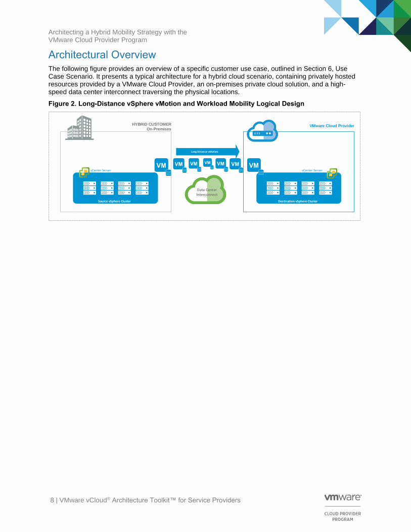
Architectural Overview The following figure provides an overview of a specific customer use case, outlined in Section 6, Use Case Scenario. It presents a typical architecture for a hybrid cloud scenario, containing privately hosted resources provided by a VMware Cloud Provider, an on-premises private cloud solution, and a high-speed data center interconnect traversing the physical locations.
Figure 2. Long-Distance vSphere vMotion and Workload Mobility Logical Design
VMware Cloud Provider
Source vSphere Cluster Destination vSphere Cluster
vCenter Server vCenter Server
HYBRID CUSTOMER
On-Premises
Long Distance vMotion
Data CenterInterconnect

Architecting a Hybrid Mobility Strategy with the VMware Cloud Provider Program
9 | VMware vCloud® Architecture Toolkit™ for Service Providers
Customer Business Case Rainpole.com is a medium-sized online sports media company that does a large part of their business over the Web. It is critical for Rainpole.com to have an infrastructure that provides a way to contain costs through operational efficiency, and also gives them the agility and responsiveness required in the Internet-facing world. In this example, their customers are spread across the globe, service quality expectations are high, and their competitors are only a few clicks away.
Use Case Scenario Rainpole.com is launching a new online sports service. The marketing and sales departments are not able to provide a reliable forecast of the number of customers expected to use the service. They have warned their IT organization that visibility in the market for this service will be subject to a large degree of variability with high peaks that coincide with specific sporting events.
Rainpole.com currently houses their entire IT infrastructure in a single physical location adjacent to their offices. A mandate from the executive board states that this single point of failure can no longer be tolerated, and action is required before the launch of the new online sports service.
Outsourcing a dedicated infrastructure to take advantage of a service provider’s resource elasticity is not an option because there is a shared back end with other online services running on-premises. In addition, as the back end is not uniquely tied to the specific new offering, it cannot be moved off-premises, and some of the data in the back end databases is sensitive, so Rainpole.com wants to keep it inside their firewall.
For these reasons, Rainpole.com is evaluating an innovative hybrid deployment model that enables them to gain flexibility and comply with their constraints. Additional Rainpole.com business requirements include the following:
• Live migration of workloads from on-premises to the provider’s data center, and maintaining virtual machine sessions before, during, and after the live migration
• Continuous data availability of online services
• Approximately 200 km between on-premises and chosen VMware Cloud Provider’s data center
• Costing must be based on a OPEX-based model
• The ability to perform a permanent migration for virtual machine services to the VMware Cloud Provider’s data center
• The ability to migrate virtual machines to the service provider’s site to avoid imminent disaster
• The ability to distribute applications with flexibility across physical sites to balance system load
Architecting a Hybrid Mobility Strategy with the VMware Cloud Provider Program
10 | VMware vCloud® Architecture Toolkit™ for Service Providers
Conceptual Overview vSphere 6 long-distance vSphere vMotion provides the ability to move workloads and to share and load balance IT assets and resources across physical locations, which has been a goal of IT departments since the introduction of virtualized servers. One of the main drivers for the continued adoption of virtualized servers is the control it gives businesses, along with the flexibility and agility that comes with decoupling the hardware and software from one another. This means that vSphere 6 functionality enables the development of new architectures that address specific customer use cases and can be adapted as required to specific customer and provider environments.
The solution proposed takes advantage of vSphere 6 long distance functionality and advanced network technologies to facilitate seamless virtual machine mobility. In Rainpole.com’s virtualized environment, the ability to dynamically and manually redistribute virtual machines to the new service provider’s location gives the opportunity for value-added services, operationally efficiency, and disaster avoidance.
The requirements for long-distance vSphere vMotion include that the maximum latency between the source and destination sites must be 150 ms round-trip time (RTT) or less, and that there are 250 Mbps of available bandwidth. For a complete list of requirements, see the VMware Knowledge Base article, Long Distance vMotion requirements in VMware vSphere 6.0 (2106949) at http://kb.vmware.com/kb/2106949
The virtual machine network must be a stretched Layer 2 extension, because the IP address of the guest operating system does not change during the vSphere vMotion operation. If the destination port group is not in the same Layer 2 address space as the source, network connectivity to the guest operating system will be lost. This means that stretched Layer 2 technology is a requirement. VMware does not recommend any specific stretched Layer 2 technology. Any technology that can present the same Layer 2 network to the vSphere hosts at each physical location will work because the physical network configuration is irrelevant to VMware ESXi™. Examples of valid technologies include VXLAN, VMware NSX® Layer 2 gateway services, Cisco OTV, and GIF/GRE tunnels. There is no defined maximum distance between source and destination networks that are supported by VMware, as long as the network meets the previously described requirements.
Architects must understand that long distance vSphere vMotion performance varies because it is constrained by the laws of physics. With one of the long distance vSphere vMotion requirements stating that the ESXi source and target hosts must be within 150 ms RTT from one another, consider the practical implications in defining Rainpole.com’s virtualized workload mobility use case with respect to how far the physical data centers can be located from one another. Therefore, the 150 ms RTT requirement must be translated into a physical distance between locations, and many variables exist in these calculations.
First, consider that the support requirement is a 150 ms RTT response time. From that it can be calculated that the distance between the physical locations is based on using 75 ms as the one-way support requirement. In a vacuum (a space that is devoid of matter), the speed of light travels at 299,792,458 m per second, and this figure can be used to convert to the time it takes to travel 1 km.
Architecting a Hybrid Mobility Strategy with the VMware Cloud Provider Program
11 | VMware vCloud® Architecture Toolkit™ for Service Providers
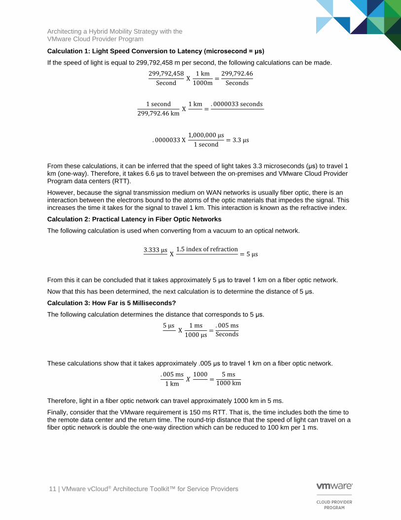
Calculation 1: Light Speed Conversion to Latency (microsecond = μs)
If the speed of light is equal to 299,792,458 m per second, the following calculations can be made.
299,792,458
Second X
1 km
1000m=
299,792.46
Seconds
1 second
299,792.46 km X
1 km=
. 0000033 seconds
. 0000033 X 1,000,000 μs
1 second= 3.3 μs
From these calculations, it can be inferred that the speed of light takes 3.3 microseconds (μs) to travel 1 km (one-way). Therefore, it takes 6.6 μs to travel between the on-premises and VMware Cloud Provider Program data centers (RTT).
However, because the signal transmission medium on WAN networks is usually fiber optic, there is an interaction between the electrons bound to the atoms of the optic materials that impedes the signal. This increases the time it takes for the signal to travel 1 km. This interaction is known as the refractive index.
Calculation 2: Practical Latency in Fiber Optic Networks
The following calculation is used when converting from a vacuum to an optical network.
3.333 μs X
1.5 index of refraction= 5 μs
From this it can be concluded that it takes approximately 5 μs to travel 1 km on a fiber optic network.
Now that this has been determined, the next calculation is to determine the distance of 5 μs.
Calculation 3: How Far is 5 Milliseconds?
The following calculation determines the distance that corresponds to 5 μs.
5 μs X
1 ms
1000 μs=
. 005 ms
Seconds
These calculations show that it takes approximately .005 μs to travel 1 km on a fiber optic network.
. 005 ms
1 km 𝑋
1000=
5 ms
1000 km
Therefore, light in a fiber optic network can travel approximately 1000 km in 5 ms.
Finally, consider that the VMware requirement is 150 ms RTT. That is, the time includes both the time to the remote data center and the return time. The round-trip distance that the speed of light can travel on a fiber optic network is double the one-way direction which can be reduced to 100 km per 1 ms.
Architecting a Hybrid Mobility Strategy with the VMware Cloud Provider Program
12 | VMware vCloud® Architecture Toolkit™ for Service Providers
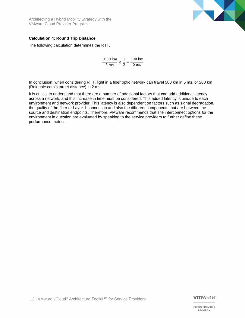
Calculation 4: Round Trip Distance
The following calculation determines the RTT.
1000 km
5 ms 𝑋
1
2=
500 km
5 ms
In conclusion, when considering RTT, light in a fiber optic network can travel 500 km in 5 ms, or 200 km (Rainpole.com’s target distance) in 2 ms.
It is critical to understand that there are a number of additional factors that can add additional latency across a network, and this increase in time must be considered. This added latency is unique to each environment and network provider. This latency is also dependent on factors such as signal degradation, the quality of the fiber or Layer 1 connection and also the different components that are between the source and destination endpoints. Therefore, VMware recommends that site interconnect options for the environment in question are evaluated by speaking to the service providers to further define these performance metrics.
Architecting a Hybrid Mobility Strategy with the VMware Cloud Provider Program
13 | VMware vCloud® Architecture Toolkit™ for Service Providers
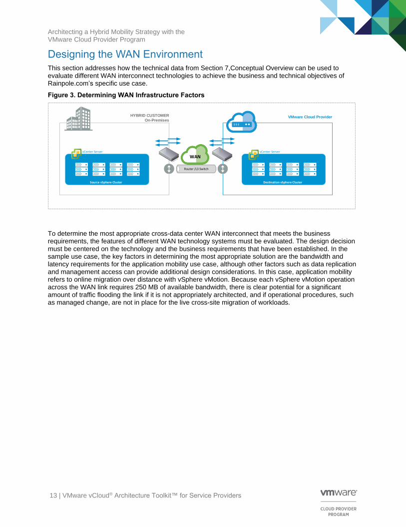
Designing the WAN Environment This section addresses how the technical data from Section 7,Conceptual Overview can be used to evaluate different WAN interconnect technologies to achieve the business and technical objectives of Rainpole.com’s specific use case.
Figure 3. Determining WAN Infrastructure Factors
VMware Cloud Provider
Source vSphere Cluster Destination vSphere Cluster
vCenter Server vCenter Server
HYBRID CUSTOMER
On-Premises
WAN
Router /L3 Switch
To determine the most appropriate cross-data center WAN interconnect that meets the business requirements, the features of different WAN technology systems must be evaluated. The design decision must be centered on the technology and the business requirements that have been established. In the sample use case, the key factors in determining the most appropriate solution are the bandwidth and latency requirements for the application mobility use case, although other factors such as data replication and management access can provide additional design considerations. In this case, application mobility refers to online migration over distance with vSphere vMotion. Because each vSphere vMotion operation across the WAN link requires 250 MB of available bandwidth, there is clear potential for a significant amount of traffic flooding the link if it is not appropriately architected, and if operational procedures, such as managed change, are not in place for the live cross-site migration of workloads.
Architecting a Hybrid Mobility Strategy with the VMware Cloud Provider Program
14 | VMware vCloud® Architecture Toolkit™ for Service Providers
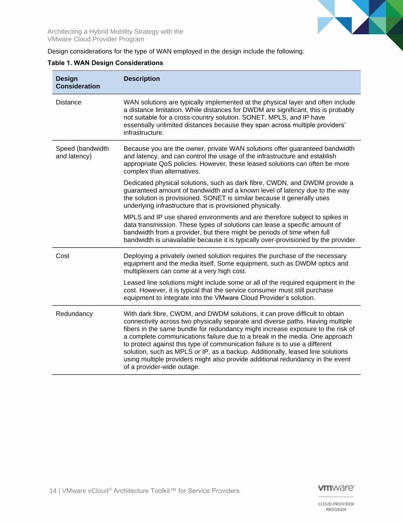
Design considerations for the type of WAN employed in the design include the following.
Table 1. WAN Design Considerations
Design Consideration
Description
Distance WAN solutions are typically implemented at the physical layer and often include a distance limitation. While distances for DWDM are significant, this is probably not suitable for a cross-country solution. SONET, MPLS, and IP have essentially unlimited distances because they span across multiple providers’ infrastructure.
Speed (bandwidth and latency)
Because you are the owner, private WAN solutions offer guaranteed bandwidth and latency, and can control the usage of the infrastructure and establish appropriate QoS policies. However, these leased solutions can often be more complex than alternatives.
Dedicated physical solutions, such as dark fibre, CWDN, and DWDM provide a guaranteed amount of bandwidth and a known level of latency due to the way the solution is provisioned. SONET is similar because it generally uses underlying infrastructure that is provisioned physically.
MPLS and IP use shared environments and are therefore subject to spikes in data transmission. These types of solutions can lease a specific amount of bandwidth from a provider, but there might be periods of time when full bandwidth is unavailable because it is typically over-provisioned by the provider.
Cost Deploying a privately owned solution requires the purchase of the necessary equipment and the media itself. Some equipment, such as DWDM optics and multiplexers can come at a very high cost.
Leased line solutions might include some or all of the required equipment in the cost. However, it is typical that the service consumer must still purchase equipment to integrate into the VMware Cloud Provider’s solution.
Redundancy With dark fibre, CWDM, and DWDM solutions, it can prove difficult to obtain connectivity across two physically separate and diverse paths. Having multiple fibers in the same bundle for redundancy might increase exposure to the risk of a complete communications failure due to a break in the media. One approach to protect against this type of communication failure is to use a different solution, such as MPLS or IP, as a backup. Additionally, leased line solutions using multiple providers might also provide additional redundancy in the event of a provider-wide outage.
Architecting a Hybrid Mobility Strategy with the VMware Cloud Provider Program
15 | VMware vCloud® Architecture Toolkit™ for Service Providers
WAN links can broadly be defined as one of the following three options:
• Private WAN: Owned and managed by the user’s business. They are expensive and potentially very labor intensive to implement and maintain. They can also be difficult to reconfigure for dynamically changing business requirements. The primary advantages of using private WAN links include higher levels of security and transmission quality.
• Leased WAN: Maintained by a service provider, although the user’s business might be required to purchase additional hardware to provide connectivity. The consumer typically pays for the allocated bandwidth regardless of its utilization.
• Shared WAN: A shared environment where the service provider is responsible for all operational maintenance, although the user’s business might be required to purchase additional hardware to provide connectivity. While a shared WAN link is typically the least expensive option to deploy and maintain, they also bare the highest security risks and the potential for resource conflicts, depending on configuration.
Architecting a Hybrid Mobility Strategy with the VMware Cloud Provider Program
16 | VMware vCloud® Architecture Toolkit™ for Service Providers
Evaluation of WAN Platforms This section provides further evaluation of each WAN platform in our scope so that the appropriate features can be mapped against Rainpole.com’s application and business requirements.
9.1 Dark Fibre
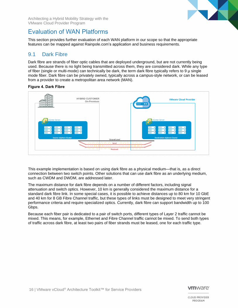
Dark fibre are strands of fiber optic cables that are deployed underground, but are not currently being used. Because there is no light being transmitted across them, they are considered dark. While any type of fiber (single or multi-mode) can technically be dark, the term dark fibre typically refers to 9 µ single mode fiber. Dark fibre can be privately owned, typically across a campus-style network, or can be leased from a provider to create a metropolitan area network (MAN).
Figure 4. Dark Fibre
VMware Cloud Provider
Source vSphere Cluster Destination vSphere Cluster
vCenter Server vCenter Server
HYBRID CUSTOMER
On-Premises
Send
Received
Ground Level
This example implementation is based on using dark fibre as a physical medium—that is, as a direct connection between two switch points. Other solutions that can use dark fibre as an underlying medium, such as CWDM and DWDM, are addressed later.
The maximum distance for dark fibre depends on a number of different factors, including signal attenuation and switch optics. However, 10 km is generally considered the maximum distance for a standard dark fibre link. In some special cases, it is possible to achieve distances up to 80 km for 10 GbE and 40 km for 8 GB Fibre Channel traffic, but these types of links must be designed to meet very stringent performance criteria and require specialized optics. Currently, dark fibre can support bandwidth up to 100 Gbps.
Because each fiber pair is dedicated to a pair of switch ports, different types of Layer 2 traffic cannot be mixed. This means, for example, Ethernet and Fibre Channel traffic cannot be mixed. To send both types of traffic across dark fibre, at least two pairs of fiber strands must be leased, one for each traffic type.

Architecting a Hybrid Mobility Strategy with the VMware Cloud Provider Program
17 | VMware vCloud® Architecture Toolkit™ for Service Providers
In summary, dark fibre has the following key design considerations:
• 9 µ single mode fiber
• Viable for campuses and extended distances
• Used in pairs
• Can support any available bandwidth
• Typical distance is up to 10 km
• Up to 80 km possible with 10 GbE and specialized components and media
• Up to 40 km possible with 8 GB Fibre Channel and specialized components and media
9.2 Wavelength Division Multiplexing (DWDM and CWDM)
Wavelength division multiplexing (WDM) is a mechanism used to simultaneously transmit multiple streams of data on a single strand of fiber (or pair of fibers). Using WDM allows the customer to overcome the limitation of needing a separate fiber pair for each type of traffic that they want to transmit (unlike dark fibre). There are two different types of WDM—Dense WDM (DWDM) and Coarse WDM (CWDM).
DWDM, as its name suggests, supports more wavelengths because they are spaced together more tightly. Because the wavelength separation is so small, DWDM requires high-precision equipment that is typically very costly to purchase.
Figure 5. Wave Division Multiplexing (DWDM and CWDM)
VMware Cloud Provider
Source vSphere Cluster Destination vSphere Cluster
vCenter Server vCenter Server
HYBRID CUSTOMER
On-Premises
Router
FC Switch
SONET
Router
FC Switch
SONET
Transponder
Transponder
Transponder
Transponder
Transponder
Transponder
MultiplexerMultiplexer
This equipment provides filters to the light emitted from the data source, such as the switch, then multiplexes it onto the fiber strands along with the light from other sources. At the far end of the fiber strand, another multiplexer separates the signals from the different sources and forwards them to the appropriate destination equipment. Because the signals are also amplified by the DWDM system, they can travel much further than with native dark fibre. With the right hardware and media components in place, DWDM can potentially be extended to thousands of kilometers. The number of different wavelengths that can be supported by DWDM varies by vendor, but 32, 64, and even 128 are possible.
Architecting a Hybrid Mobility Strategy with the VMware Cloud Provider Program
18 | VMware vCloud® Architecture Toolkit™ for Service Providers
In summary, DWDM has the following key design considerations:
• Most typically used over short distances, such as 100 km to 200 km, but can extend further
• Dark fibre must be available
• Divides a single beam of light into discrete wavelengths (lamdas)
• Each signal can be carried at a different rate
• Dedicated bandwidth for each multiplexed channel. Approximately 0.4 nm spacing
• DWDM transponders can support multiple protocols and speeds (LAN, SAN, and other signals)
CWDM was introduced as a lower-cost alternative to DWDM. The functionality is almost identical to DWDM, except that the wavelengths (called channels in CWDM) are spaced further apart. The result of this is that fewer channels can fit on the fiber strands (maximum of 16 channels per fiber pair). Also, CWDM does not require as many components as DWDM, and those components are significantly less costly. However, a CWDM solution does not amplify and clean the signal as DWDM does, so the distance limitations for CWDM are significantly lower. In most implementations, the maximum distance is typically less the 100 km, but multiple signals, such as Ethernet and Fibre Channel, can be carried, giving it a significant advantage over native dark fibre.
9.3 SONET/SDH
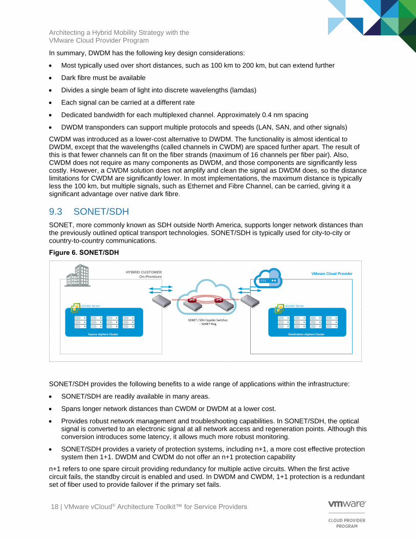
SONET, more commonly known as SDH outside North America, supports longer network distances than the previously outlined optical transport technologies. SONET/SDH is typically used for city-to-city or country-to-country communications.
Figure 6. SONET/SDH
VMware Cloud Provider
Source vSphere Cluster Destination vSphere Cluster
vCenter Server vCenter Server
HYBRID CUSTOMER
On-Premises
SONET / SDH Capable Switches – SONET Ring
SONET/SDH provides the following benefits to a wide range of applications within the infrastructure:
• SONET/SDH are readily available in many areas.
• Spans longer network distances than CWDM or DWDM at a lower cost.
• Provides robust network management and troubleshooting capabilities. In SONET/SDH, the optical signal is converted to an electronic signal at all network access and regeneration points. Although this conversion introduces some latency, it allows much more robust monitoring.
• SONET/SDH provides a variety of protection systems, including n+1, a more cost effective protection system then 1+1. DWDM and CWDM do not offer an n+1 protection capability
n+1 refers to one spare circuit providing redundancy for multiple active circuits. When the first active circuit fails, the standby circuit is enabled and used. In DWDM and CWDM, 1+1 protection is a redundant set of fiber used to provide failover if the primary set fails.

Architecting a Hybrid Mobility Strategy with the VMware Cloud Provider Program
19 | VMware vCloud® Architecture Toolkit™ for Service Providers
In summary, SONET/SDH has the following key design considerations:
• SONET/SDH supports longer distances than WDM
• Most typically used over short and intermediate distances
• Used when dark fibre is not available
• Robust network management and troubleshooting
• Significant installed infrastructure required
• Variety of protection systems offered
• Can be combined with DWDM to increase capacity or redundancy
9.4 Multiprotocol Label Switching (MPLS)
Multiprotocol Label Switching (MPLS) functions similarly to IP, but the infrastructure switches based on a predetermined path instead of calculating paths hop-to-hop. MPLS can also operate on a variety of Layer 2 infrastructures.
For an MPLS or IP interconnect between data centers, the design changes from the fiber model. Because the interconnect between the data centers is a Layer 2.5 or Layer 3 link, Layer 2 connectivity is not available beyond the data center boundary. However, because long distance vSphere vMotion is a design goal for the sample use case, to perform the same actions as a fiber link, with cross-site Layer 2 adjacency (routed over a Layer 3 network) when using an IP-based WAN, a tunnel must be established between the two sites and the Ethernet data encapsulated within that tunnel structure.
Figure 7. Multiprotocol Label Switching (MPLS)
VMware Cloud Provider
Source vSphere Cluster Destination vSphere Cluster
vCenter Server vCenter Server
HYBRID CUSTOMER
On-Premises
A Z X
WY
V
U
B
C
Destination Path B Z,Y,W,V,UC Z,Y,X,V,U

Architecting a Hybrid Mobility Strategy with the VMware Cloud Provider Program
20 | VMware vCloud® Architecture Toolkit™ for Service Providers
In summary, MPLS has the following key design considerations:
• Layer 2.5 protocol
• Used over short or long distances
• Used when dark fibre is not available
• Links might be shared
• Operates over a variety of Layer 2 infrastructures
• Switches based on label
• Uses predefined paths, reducing delays from dynamically calculated paths
• MPLS performance (which affects delay, jitter, failover, and so on) is dependant of Service Provider SLAs
Architecting a Hybrid Mobility Strategy with the VMware Cloud Provider Program
21 | VMware vCloud® Architecture Toolkit™ for Service Providers
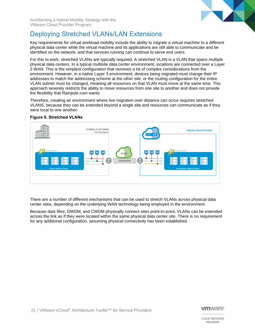
Deploying Stretched VLANs/LAN Extensions Key requirements for virtual workload mobility include the ability to migrate a virtual machine to a different physical data center while the virtual machine and its applications are still able to communicate and be identified on the network, and that services running can continue to serve end users.
For this to work, stretched VLANs are typically required. A stretched VLAN is a VLAN that spans multiple physical data centers. In a typical multisite data center environment, locations are connected over a Layer 3 WAN. This is the simplest configuration that removes a lot of complex considerations from the environment. However, in a native Layer 3 environment, devices being migrated must change their IP addresses to match the addressing scheme at the other site, or the routing configuration for the entire VLAN subnet must be changed, meaning all resources on that VLAN must move at the same time. This approach severely restricts the ability to move resources from one site to another and does not provide the flexibility that Rainpole.com wants.
Therefore, creating an environment where live migration over distance can occur requires stretched VLANS, because they can be extended beyond a single site and resources can communicate as if they were local to one another.
Figure 8. Stretched VLANs
VMware Cloud Provider
Source vSphere Cluster Destination vSphere Cluster
vCenter Server vCenter Server
HYBRID CUSTOMER
On-Premises
WAN
VLAN 20,30,40VLAN 20
VLAN 30
VLAN 40
VLAN 20
VLAN 30
VLAN 40
There are a number of different mechanisms that can be used to stretch VLANs across physical data center sites, depending on the underlying WAN technology being employed in the environment.
Because dark fibre, DWDM, and CWDM physically connect sites point-to-point, VLANs can be extended across the link as if they were located within the same physical data center site. There is no requirement for any additional configuration, assuming physical connectivity has been established.
Architecting a Hybrid Mobility Strategy with the VMware Cloud Provider Program
22 | VMware vCloud® Architecture Toolkit™ for Service Providers
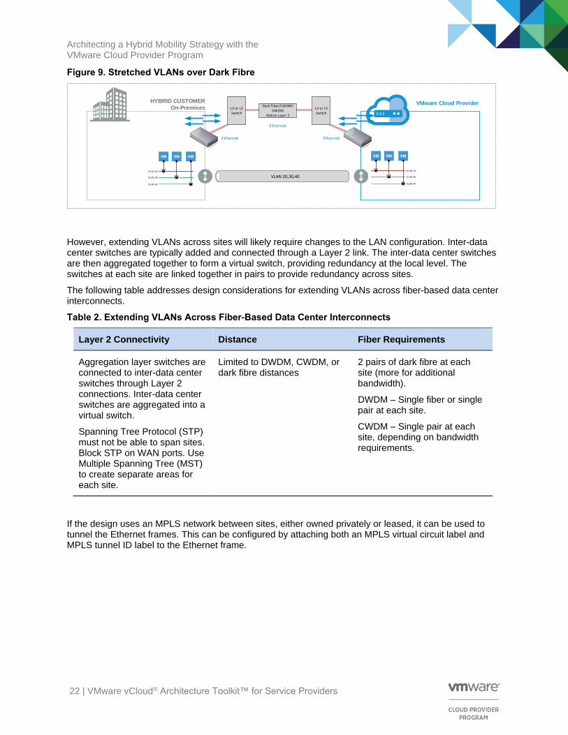
Figure 9. Stretched VLANs over Dark Fibre
VMware Cloud Provider HYBRID CUSTOMER
On-Premises
VLAN 20,30,40VLAN 20
VLAN 30
VLAN 40
VLAN 20
VLAN 30
VLAN 40
Dark Fiber/CWDM/DWDM
Native Layer 2
L2 or L3 Switch
L2 or L3 Switch
Ethernet
Ethernet Ethernet
However, extending VLANs across sites will likely require changes to the LAN configuration. Inter-data center switches are typically added and connected through a Layer 2 link. The inter-data center switches are then aggregated together to form a virtual switch, providing redundancy at the local level. The switches at each site are linked together in pairs to provide redundancy across sites.
The following table addresses design considerations for extending VLANs across fiber-based data center interconnects.
Table 2. Extending VLANs Across Fiber-Based Data Center Interconnects
Layer 2 Connectivity Distance Fiber Requirements
Aggregation layer switches are connected to inter-data center switches through Layer 2 connections. Inter-data center switches are aggregated into a virtual switch.
Spanning Tree Protocol (STP) must not be able to span sites. Block STP on WAN ports. Use Multiple Spanning Tree (MST) to create separate areas for each site.
Limited to DWDM, CWDM, or dark fibre distances
2 pairs of dark fibre at each site (more for additional bandwidth).
DWDM – Single fiber or single pair at each site.
CWDM – Single pair at each site, depending on bandwidth requirements.
If the design uses an MPLS network between sites, either owned privately or leased, it can be used to tunnel the Ethernet frames. This can be configured by attaching both an MPLS virtual circuit label and MPLS tunnel ID label to the Ethernet frame.
Architecting a Hybrid Mobility Strategy with the VMware Cloud Provider Program
23 | VMware vCloud® Architecture Toolkit™ for Service Providers
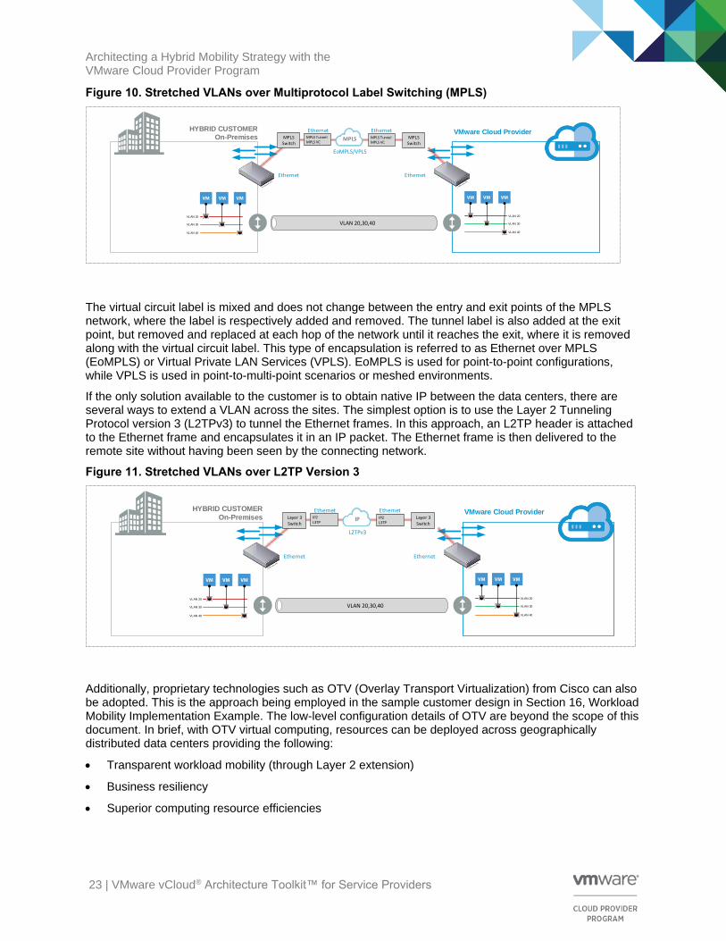
Figure 10. Stretched VLANs over Multiprotocol Label Switching (MPLS)
VMware Cloud Provider HYBRID CUSTOMER
On-Premises
VLAN 20,30,40VLAN 20
VLAN 30
VLAN 40
VLAN 20
VLAN 30
VLAN 40
MPLS Switch
EoMPLS/VPLS
Ethernet Ethernet
MPLSMPLS Tunnel MPLS VC
MPLS Tunnel MPLS VC
Ethernet EthernetMPLS Switch
The virtual circuit label is mixed and does not change between the entry and exit points of the MPLS network, where the label is respectively added and removed. The tunnel label is also added at the exit point, but removed and replaced at each hop of the network until it reaches the exit, where it is removed along with the virtual circuit label. This type of encapsulation is referred to as Ethernet over MPLS (EoMPLS) or Virtual Private LAN Services (VPLS). EoMPLS is used for point-to-point configurations, while VPLS is used in point-to-multi-point scenarios or meshed environments.
If the only solution available to the customer is to obtain native IP between the data centers, there are several ways to extend a VLAN across the sites. The simplest option is to use the Layer 2 Tunneling Protocol version 3 (L2TPv3) to tunnel the Ethernet frames. In this approach, an L2TP header is attached to the Ethernet frame and encapsulates it in an IP packet. The Ethernet frame is then delivered to the remote site without having been seen by the connecting network.
Figure 11. Stretched VLANs over L2TP Version 3
VMware Cloud Provider HYBRID CUSTOMER
On-Premises
VLAN 20,30,40VLAN 20
VLAN 30
VLAN 40
VLAN 20
VLAN 30
VLAN 40
Layer 3 Switch
L2TPv3
Ethernet Ethernet
IPIP2L3TP
IP2L3TP
Ethernet EthernetLayer 3 Switch
Additionally, proprietary technologies such as OTV (Overlay Transport Virtualization) from Cisco can also be adopted. This is the approach being employed in the sample customer design in Section 16, Workload Mobility Implementation Example. The low-level configuration details of OTV are beyond the scope of this document. In brief, with OTV virtual computing, resources can be deployed across geographically distributed data centers providing the following:
• Transparent workload mobility (through Layer 2 extension)
• Business resiliency
• Superior computing resource efficiencies
Architecting a Hybrid Mobility Strategy with the VMware Cloud Provider Program
24 | VMware vCloud® Architecture Toolkit™ for Service Providers
10.1 Stretched VLAN/LAN Extension Technical Requirements
LAN extension refers to the concept of extending Layer 2 networks beyond the traditional Layer 3 boundaries of a single data center. As discussed in the previous section, the ability to live migrate workloads from one physical data center to another is completely dependent on the ability of the Layer 2 network to exist at the destination data center, and on the virtual machine being able to communicate after migration.
While stretching VLANs and address space across two different physical locations facilitates the type of workload mobility being discussed in this paper, it also presents a number of challenges because providing these types of LAN extensions have a big impact on network design.
Unfortunately, it is not possible to simply allow Layer 2 connectivity between data centers using only Layer 3 technologies because this would have significant consequences on traffic patterns between the two data centers, such as STP, unicast floods, broadcasts, and ARP requests. Therefore, technology must be included that employs extended spanning-tree techniques to avoid loops and broadcast storms, and that understands where an active IP address on the subnet exists at any given time.
For further information, refer to your network equipment’s vendor documentation or seek guidance from a network architect who is able to evaluate all of the requirements and constraints of a specific environment. However, when considering the deployment of a LAN extension across different physical sites, it is important to address as key requirements both STP isolation and end-to-end loop prevention to mitigate significant disruptions likely to be caused by remote data center failure or the propagation of unwanted behavior from one data center to the other.
Architecting a Hybrid Mobility Strategy with the VMware Cloud Provider Program
25 | VMware vCloud® Architecture Toolkit™ for Service Providers
WAN Interconnect High Availability High availability for data center interconnect WAN links is significantly more complex than it is for a LAN environment due to factors such as distance, cost, non-ownership of equipment, and connectivity. The HA model for WAN connectivity varies widely depending on the type of WAN being employed. In general, a typical WAN HA solution can be classified as either including redundant components, redundant links, or both.
Redundant components means having multiple devices, such as routers or multiplexers, at each site. This provides redundancy in the event of component failure and allows for non-disruptive maintenance and upgrades. Redundant links refers to having multiple connections between data centers. This can be achieved through multiple dedicated media, such as multiple strands of dark fibre, or through a combination of fiber and a shared medium, such as MPLS. Provide a combination of both methodologies to have a fully redundant data path for the highest level of availability.
Some service providers might also provide the option of having a standby connection. This option often has a lower total cost of ownership because you are charged by the amount of data transmitted. This might be a cost-effective way of achieving a redundant link without having to pay for unrequired bandwidth.
Before making the appropriate design decision about WAN availability, understand the available options and what needs to be protected against. For example, deploying redundant links or components does not provide any benefit if the single ISP has a large-scale outage.
Architecting a Hybrid Mobility Strategy with the VMware Cloud Provider Program
26 | VMware vCloud® Architecture Toolkit™ for Service Providers
Secure Communication The primary method used to secure data as it transverses between data center sites is IPsec, or Internet Protocol Security. IPsec is commonly used to encrypt portions of the IP packet. The dataflow is encrypted at the edge of one site and then decrypted at the entry point to the second site. IPsec has two different modes of operation:
• Transport mode
• Tunnel mode
Transport mode only encrypts the IP packets payload and leaves the header in an unencrypted state so it can be read by other network devices. However, in tunnel mode, the entire IP packet, including its header, is encrypted, meaning that it must be encapsulated in another IP packet with an unencrypted header. This way the source and destination information in the header of the packet can be read by network devices. Tunnel mode is most commonly used for point-to-point or site-to-site VPNs.
WAN Considerations Summary
When evaluating the options to achieve the most viable design for the proposed hybrid architecture, a number of key design factors must be considered. The following table highlights the key drivers for most designs.
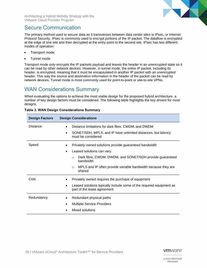
Table 3. WAN Design Considerations Summary
Design Factors Design Considerations
Distance • Distance limitations for dark fibre, CWDM, and DWDM
• SONET/SDH, MPLS, and IP have unlimited distances, but latency must be considered
Speed • Privately owned solutions provide guaranteed bandwidth
• Leased solutions can vary.
o Dark fibre, CWDM, DWDM, and SONET/SDH provide guaranteed bandwidth
o MPLS and IP often provide variable bandwidth because they are shared
Cost • Privately owned requires the purchase of equipment
• Leased solutions typically include some of the required equipment as part of the lease agreement
Redundancy • Redundant physical paths
• Multiple Service Providers
• Mixed solutions

Architecting a Hybrid Mobility Strategy with the VMware Cloud Provider Program
27 | VMware vCloud® Architecture Toolkit™ for Service Providers
Long-Distance Networking Summary The following table contains a summary of the WAN technologies discussed that could potentially be used for our specific use case, to connect multiple data centers. Note that the values provided here are generalizations. The actual values depend on various factors such as the Service Provider’s equipment, media, and so on.
Table 4. Long-Distance Networking Summary
Dark Fibre CWDM DWDM SONET/SDH MPLS IP (Internet)
Distance 40 km+ Less than 100 km
Up to 200 km (see Note)
1000s of km Unlimited Unlimited
Latency 5 μs /km 5 μs /km Low Medium Variable Variable (high)
Channels N/A Up to 16 100+ N/A N/A N/A
Bandwidth 100 Gbps+ 10 Gbps (per channel)
40 Gbps (per channel)
10 Gbps Variable Variable
Reliability 1x10 12 1x10 12 High High High High
Cost Low/High Medium High Medium Low Low
Type Private Leased
Private Leased
Private Leased
Leased Private Leased
Shared
Note With the appropriate equipment and media, DWDM can be extended beyond 200 km, but 200 km is the typical limitation for most use cases.

Architecting a Hybrid Mobility Strategy with the VMware Cloud Provider Program
28 | VMware vCloud® Architecture Toolkit™ for Service Providers
VMware Requirements for Long-Distance vSphere vMotion vSphere vMotion is the method used by vSphere to migrate active virtual machines from one physical ESXi host to another. Even though previous releases of vSphere had some limitations on this functionality, vSphere vMotion is perhaps the most powerful feature of a vSphere virtual environment, allowing the migration of active virtual machines with zero downtime. A vSphere vMotion event can either be initiated manually by operational teams through the VMware management tools, or VMware vCenter Server® can automatically initiate a live migration as part of the VMware vSphere Distributed Resource Scheduler™ feature, which uses this mechanism to automatically load balance virtual machines across a single cluster.
Figure 12. vSphere vMotion Process
VMware Cloud Provider
Source vSphere Cluster Destination vSphere Cluster
vCenter Server vCenter Server
HYBRID CUSTOMER
On-Premises
Long Distance vMotion
Production VM Network
vMotion Network
vRealize Operations
One of the major enhancements in vSphere 6 is the introduction of long distance vSphere vMotion, which allows migrating virtual machines from one physical data center to another.
There are several key requirements to achieve this:
• A cross data center interconnect with less than 150 ms RTT.
• Network bandwidth of at least 250 Mbps for each long distance vSphere vMotion operation.
• vSphere 6 at both the on-premises data center and the VMware Cloud Provider Program data center (source and destination).
• The same single sign-on domain across data centers (specifically, the same SSO domain is a requirement when operations are carried out through the UI). When executing the vSphere vMotion event through the vCenter Server API, it is possible for the source and destination vCenter Server instances to belong to different SSO domains.
• Cross-site Layer 2 connectivity for virtual machine networks. The IP subnet on which the virtual machine resides must be accessible from both the source and destination ESXi servers. This requirement is very important because the virtual machine retains its IP address when it moves to the destination ESXi server to help confirm that its communication with the outside world continues smoothly after the move. This is also required to allow intra-subnet communication with the devices remaining on the original site after the long distance vSphere vMotion event has completed.
• As with local data center migration, a dedicated vSphere vMotion network is strongly recommended. The VMkernel interfaces are used by the ESXi host's internal TCP/IP stack for facilitating vSphere vMotion migration of a virtual machine between ESXi hosts. Typically, the interfaces of the source and destination ESXi servers reside on the same IP subnet (the vSphere vMotion network). This is no
Architecting a Hybrid Mobility Strategy with the VMware Cloud Provider Program
29 | VMware vCloud® Architecture Toolkit™ for Service Providers
longer strictly required as a technical requirement because vSphere 6 now has support for routed vSphere vMotion traffic.
• vSphere is required to support virtual machine instances, however, cross-site workload mobility requires VMware vSphere 6 Enterprise Edition™ to support long distance vSphere vMotion migration of virtualized resources.
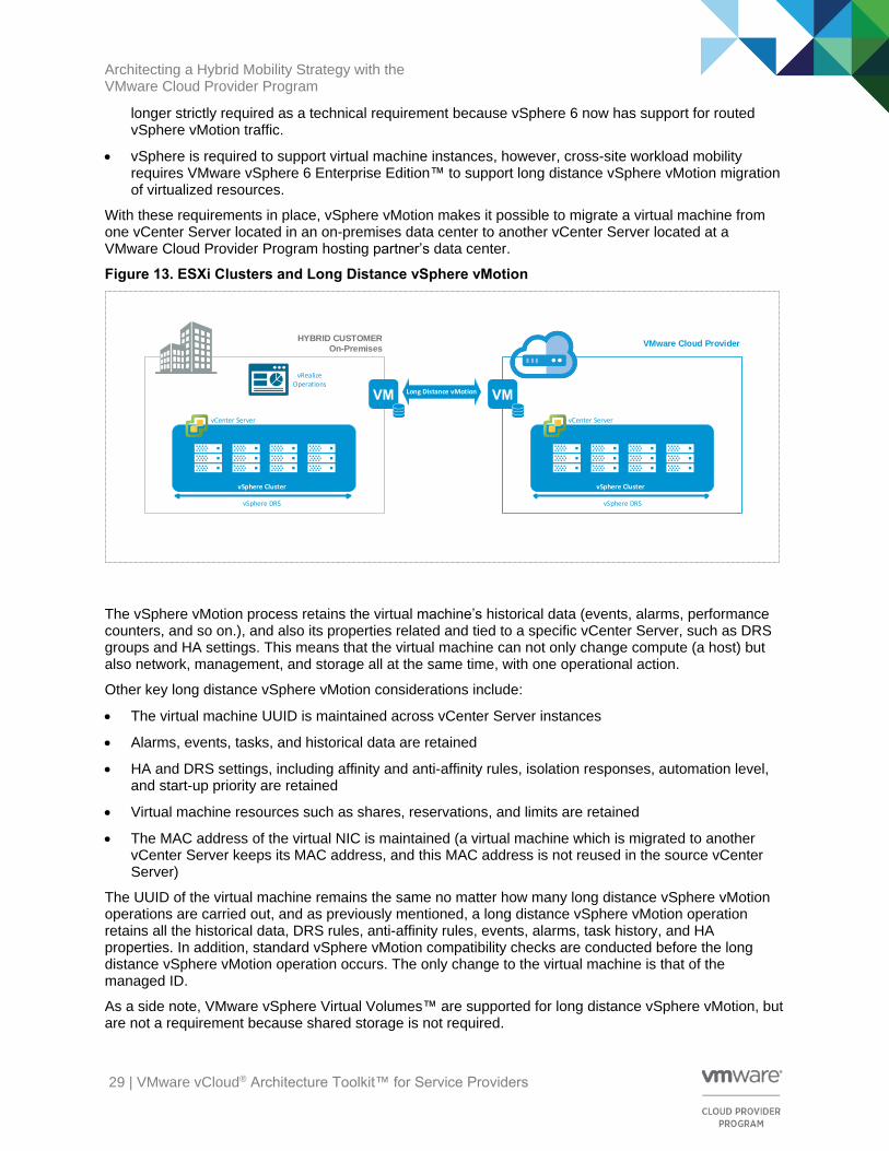
With these requirements in place, vSphere vMotion makes it possible to migrate a virtual machine from one vCenter Server located in an on-premises data center to another vCenter Server located at a VMware Cloud Provider Program hosting partner’s data center.
Figure 13. ESXi Clusters and Long Distance vSphere vMotion
vSphere Cluster
vSphere DRS
vSphere Cluster
vSphere DRS
Long Distance vMotion
vCenter Server vCenter Server
VMware Cloud Provider
vRealize Operations
HYBRID CUSTOMER
On-Premises
The vSphere vMotion process retains the virtual machine’s historical data (events, alarms, performance counters, and so on.), and also its properties related and tied to a specific vCenter Server, such as DRS groups and HA settings. This means that the virtual machine can not only change compute (a host) but also network, management, and storage all at the same time, with one operational action.
Other key long distance vSphere vMotion considerations include:
• The virtual machine UUID is maintained across vCenter Server instances
• Alarms, events, tasks, and historical data are retained
• HA and DRS settings, including affinity and anti-affinity rules, isolation responses, automation level, and start-up priority are retained
• Virtual machine resources such as shares, reservations, and limits are retained
• The MAC address of the virtual NIC is maintained (a virtual machine which is migrated to another vCenter Server keeps its MAC address, and this MAC address is not reused in the source vCenter Server)
The UUID of the virtual machine remains the same no matter how many long distance vSphere vMotion operations are carried out, and as previously mentioned, a long distance vSphere vMotion operation retains all the historical data, DRS rules, anti-affinity rules, events, alarms, task history, and HA properties. In addition, standard vSphere vMotion compatibility checks are conducted before the long distance vSphere vMotion operation occurs. The only change to the virtual machine is that of the managed ID.
As a side note, VMware vSphere Virtual Volumes™ are supported for long distance vSphere vMotion, but are not a requirement because shared storage is not required.
Architecting a Hybrid Mobility Strategy with the VMware Cloud Provider Program
30 | VMware vCloud® Architecture Toolkit™ for Service Providers
Additional design considerations associated with this type of architecture are as follows:
• vSphere 6 now supports up to 64 ESXi hosts in a single cluster.
• For Web GUI-initiated long distance vSphere vMotion operations, both on-premises and hosted clusters must be part of the same VMware Platform Services Controller™ domain. There are several ways to increase the resiliency of the vCenter Server and Platform Services Controller across multiple sites. An in-depth discussion of these methods is out of scope for this paper, but more information can be found at https://blogs.vmware.com/consulting/2015/03/vsphere-datacenter-design-vcenter-architecture-changes-vsphere-6-0-part-1.html.
• VMware functionalities such as vSphere DRS, vSphere Multi-Processor Fault Tolerance (SMP-FT), and VMware vSphere High Availability (HA) are only available for ESXi hosts that belong to the same cluster. Therefore, there is no possibility that a virtual machine will be dynamically moved between data center sites. As a result, all workload mobility events between the on-premises data center and the VMware Cloud Provider Program hosting partner’s data center must be manually triggered, or scheduled by an administrator through the VMware vSphere Web Client or API.
15.1 vSphere Virtual Networking
The traditional vSphere vMotion mechanism allows the user to migrate from a vSphere standard switch (VSS) to another within the same cluster or within a single VMware vSphere Distributed Switch™ (VDS). However, long distance vSphere vMotion is built on the ability of vSphere 6 to perform cross-virtual switch vSphere vMotion operations. Cross-virtual switch vSphere vMotion allows the seamless migration of a virtual machine across different virtual switches, unbounded by the networks created on those virtual switches.
Cross-virtual switch, and therefore cross-vCenter, long distance vSphere vMotion works across a mix of VSSs and VDS instances, unlike previous vSphere vMotion scenarios. vSphere 6 has removed those older limitations.
As previously discussed, to achieve long distance vSphere vMotion operations across data centers, the source and destination port groups must share the same Layer 2 address space. The network address properties within the guest operating system do not change during a vSphere vMotion operation. Be aware that when architecting a long distance vSphere vMotion solution, only the following cross-virtual switch vSphere vMotion operations are possible:
• VSS to VSS
• VSS to VDS
• VDS to VDS
Note With long distance vSphere vMotion operations, it is not possible to migrate back from a vSphere Distributed Switch to a VSS.
When designing your vSphere network infrastructure, you must consider whether to implement a VSS or a vSphere Distributed Switch. The main benefit of VSS is ease of implementation. However, by adopting a VDS, you can benefit from a number features only offered by this technology, including Network I/O Control (NIOC), Link Aggregation Control Protocol (LACP), and NetFlow.

Architecting a Hybrid Mobility Strategy with the VMware Cloud Provider Program
31 | VMware vCloud® Architecture Toolkit™ for Service Providers
Figure 14. vSphere Distributed Switch – Cross-Data Center Architecture
VMware Cloud Provider
Source vSphere Cluster Destination vSphere Cluster
vCenter Server vCenter Server
HYBRID CUSTOMER
On-Premises
Long Distance vMotion
vRealize Operations
VLAN 20
VLAN 30
VLAN 40
vSphere Distributed Switch
VLAN 20
VLAN 30
VLAN 40
vSphere Distributed Switch
Layer 2 Connectivity
vMotion Network
20
Gb
ps
20
Gb
ps
Port
Gro
ups
Po
rt G
rou
ps
In this sample design, the vSphere Distributed Switch is configured to carry all network traffic. Two 10 GB network interfaces carry all ingress and egress Ethernet traffic on all configured VLANs from each host. The user-defined networks must be configured on a port group by port group basis using the VLAN IDs shown.
All physical network switch ports connected to the 10 GB network interfaces must be configured as trunk ports. VMware recommends following the physical switch vendor’s guidance for the configuration of the hardware, with technologies such as STP and PortFast typically being enabled.
The figure also shows the port groups used to logically segment traffic by VLAN that are being stretched (when appropriate) across the two physical locations. VLAN tagging on the traffic occurs at the virtual switch level. Uplinks are configured as active/active with the load balancing algorithm choice depending on the physical switch’s EtherChannel capabilities. To align with security best practices, both the virtual and physical switches are configured to pass traffic specifically for VLANs employed by the infrastructure, as opposed to trunking all VLANs.
The Network I/O Control (NIOC) feature of vSphere Distributed Switch provides a QoS mechanism for network traffic within the ESXi host. NIOC can help prevent “bursty” vSphere vMotion traffic from flooding the network and causing issues with other important traffic, such as virtual machine and VMware vSAN™ communications. In addition to the use of NIOC, VMware recommends tagging traffic types for 802.1p QoS and configuring the physical upstream management switches with appropriate traffic-management priorities. If QoS tagging is not implemented, the value of the NIOC configuration is limited to within the hosts themselves.
15.2 vCenter Server and Platform Services Controller Design
With the release vSphere 6, a number of changes related to vCenter Server architecture for both the Windows installable version and the VMware vCenter® Server Appliance™ were made. For this reason, some design aspects and the deployment use cases have changed from previous releases. However, some considerations remain the same, such as database placement, choosing between a physical or virtual deployment, and designing an effective highly available architecture. From the perspective of achieving long distance vSphere vMotion, the key requirement is that both vCenter Server instances are part of the same SSO/Platform Services Controller domain. Because both source and destination vCenter Server instances are in the same SSO domain, using the new Enhanced Linked Mode feature found in
Architecting a Hybrid Mobility Strategy with the VMware Cloud Provider Program
32 | VMware vCloud® Architecture Toolkit™ for Service Providers
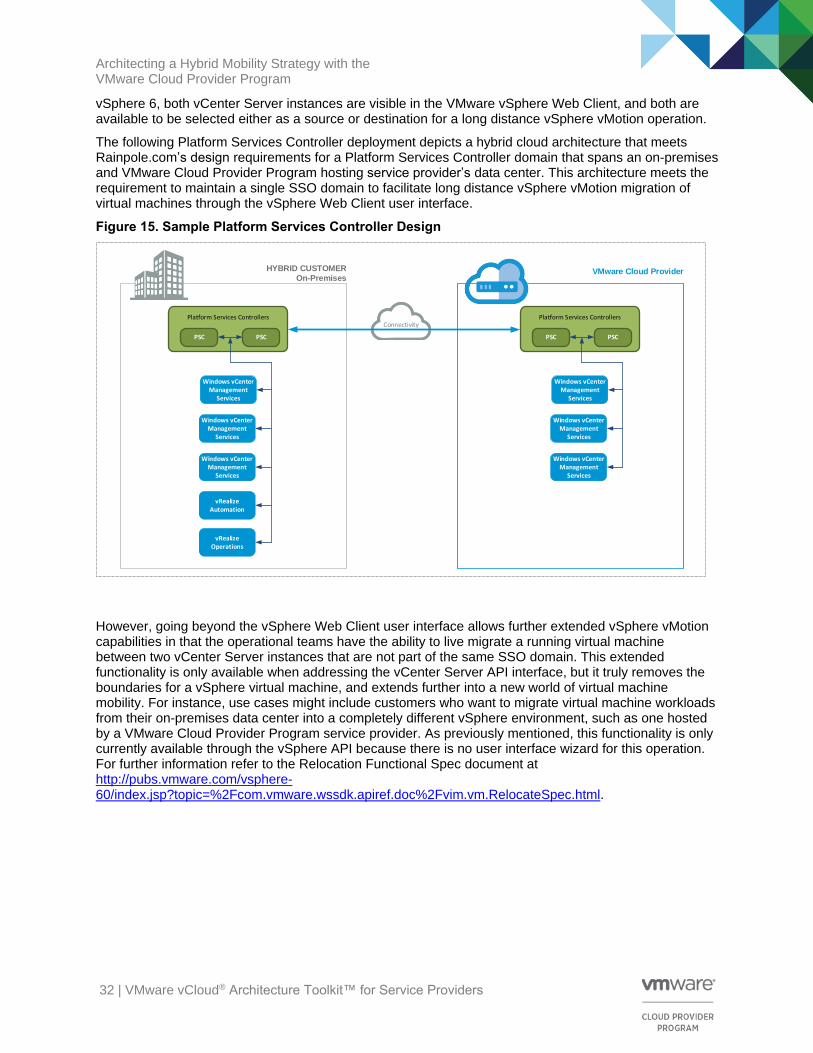
vSphere 6, both vCenter Server instances are visible in the VMware vSphere Web Client, and both are available to be selected either as a source or destination for a long distance vSphere vMotion operation.
The following Platform Services Controller deployment depicts a hybrid cloud architecture that meets Rainpole.com’s design requirements for a Platform Services Controller domain that spans an on-premises and VMware Cloud Provider Program hosting service provider’s data center. This architecture meets the requirement to maintain a single SSO domain to facilitate long distance vSphere vMotion migration of virtual machines through the vSphere Web Client user interface.
Figure 15. Sample Platform Services Controller Design
VMware Cloud Provider HYBRID CUSTOMER
On-Premises
Long Distance vMotion
Connectivity
Windows vCenterManagement
Services
PSC PSC
Windows vCenterManagement
Services
Windows vCenterManagement
Services
vRealize Automation
vRealize Operations
Platform Services Controllers
Windows vCenterManagement
Services
PSC PSC
Windows vCenterManagement
Services
Windows vCenterManagement
Services
Platform Services Controllers
However, going beyond the vSphere Web Client user interface allows further extended vSphere vMotion capabilities in that the operational teams have the ability to live migrate a running virtual machine between two vCenter Server instances that are not part of the same SSO domain. This extended functionality is only available when addressing the vCenter Server API interface, but it truly removes the boundaries for a vSphere virtual machine, and extends further into a new world of virtual machine mobility. For instance, use cases might include customers who want to migrate virtual machine workloads from their on-premises data center into a completely different vSphere environment, such as one hosted by a VMware Cloud Provider Program service provider. As previously mentioned, this functionality is only currently available through the vSphere API because there is no user interface wizard for this operation. For further information refer to the Relocation Functional Spec document at http://pubs.vmware.com/vsphere-60/index.jsp?topic=%2Fcom.vmware.wssdk.apiref.doc%2Fvim.vm.RelocateSpec.html.
Architecting a Hybrid Mobility Strategy with the VMware Cloud Provider Program
33 | VMware vCloud® Architecture Toolkit™ for Service Providers
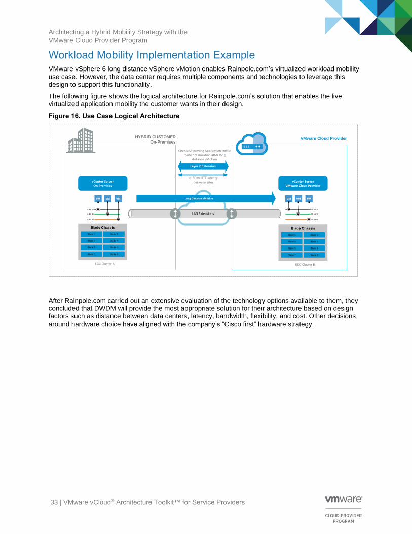
Workload Mobility Implementation Example VMware vSphere 6 long distance vSphere vMotion enables Rainpole.com’s virtualized workload mobility use case. However, the data center requires multiple components and technologies to leverage this design to support this functionality.
The following figure shows the logical architecture for Rainpole.com’s solution that enables the live virtualized application mobility the customer wants in their design.
Figure 16. Use Case Logical Architecture
VMware Cloud Provider HYBRID CUSTOMER
On-Premises
Long Distance vMotion
<150ms RTT latency between sites vCenter Server
VMware Cloud Provider
Blade 1
Blade Chassis
Blade 4
Blade 5 Blade 6
Blade 7 Blade 8
Blade 2
Blade 3
Layer 2 Extension
ESXi Cluster B
Cisco LISP proving Application traffic route optimization after long
distance vMotion
vCenter Server On-Premises
Blade 1
Blade Chassis
Blade 4
Blade 5 Blade 6
Blade 7 Blade 8
Blade 2
Blade 3
ESXi Cluster A
VLAN 20
VLAN 30
VLAN 40
VLAN 20
VLAN 30
VLAN 40
LAN Extensions
Long Distance vMotion
After Rainpole.com carried out an extensive evaluation of the technology options available to them, they concluded that DWDM will provide the most appropriate solution for their architecture based on design factors such as distance between data centers, latency, bandwidth, flexibility, and cost. Other decisions around hardware choice have aligned with the company’s “Cisco first” hardware strategy.

Architecting a Hybrid Mobility Strategy with the VMware Cloud Provider Program
34 | VMware vCloud® Architecture Toolkit™ for Service Providers
The end-to-end architecture leveraged for the virtualized workload mobility solution is shown in the following figure. This figure shows a high-level overview of the physical architecture employed to achieve the live mobility solution for Rainpole.com’s enterprise applications across two data centers. Both data centers have mirrored compute, network, and storage components from VMware and Cisco to efficiently use vSphere vMotion to move virtualized applications across sites without end users experiencing any noticeable impact to application performance. Both data centers are active and are connected by a 10 Gbps DWDM WAN link for IP communication.
Figure 17. Architecture Overview
VMware Cloud Provider HYBRID CUSTOMER
On-Premises
UCS Access
Mgmt L2
Mgmt L1
UCS 5108 CHASSIS-2
UCS 5108 CHASSIS-1
Sync Nexus 7710DC Collapsed Core/
Aggregation
Layer
Nexus 7710DC Collapsed Core/
Aggregation
Layer
UCS Access
Mgmt L2Mgmt L1
UCS 5108 CHASSIS-2
UCS 5108 CHASSIS-1
Sync
WAN Edge
Services Services
200kmDWDM
WAN Edge
Layer 3 Core
F5 GTMF5 GTM
16.1 Technology Overview
This data center architecture leverages a typical modular separation of components. Starting with compute, Rainpole.com’s design provides multiple Cisco Unified Computing System (UCS) chassis connected to a redundant pair of 6296UP Fabric Interconnect devices. Each blade in the UCS chassis represents a separate ESXi 6 host that is used to deploy multiple virtual machines. The virtual networking is provided by a single vSphere Distributed Switch at each physical location.
Each 6296UP Fabric Interconnect device is connected through a port channel to a pair of Nexus 7710 devices, representing a collapsed data center core and aggregation layer.
The pair of Nexus 7710s are then connected to the data center WAN edge to provide access to the Layer 3 core of the network (this is a WAN enterprise core offered by the same VMware Cloud Provider). The Layer 3 core of the network is where the end user and client connections accessing the specific data

Architecting a Hybrid Mobility Strategy with the VMware Cloud Provider Program
35 | VMware vCloud® Architecture Toolkit™ for Service Providers
center services and applications originate. The F5 Global Traffic Manager (GTM) devices are directly connected to the WAN edge devices.
In this design, the two data center sites are separated by 200 km and are connected through highly available, protected point-to-point DWDM circuits. As outlined previously, this represents a typical design scenario for a two data center solution.
The data center interconnect solution presents various components functioning alongside each other. The various technologies employed that are required to be considered for the implementation of the solution include, but are not limited to, the following:
• LAN extension – Given the availability of point-to-point circuits between the two sites and the hardware chosen for Rainpole.com’s design, two different options for LAN extension technologies have been considered. The first solution leverages the Cisco virtual PortChannel (Cisco vPC) capabilities of Nexus 7710 devices to establish an end-to-end port channel between the Nexus 7710 pairs deployed in each data center. The second introduces Overlay Transport Virtualization (OTV), a Cisco LAN extension technology, deployed across DWDM.
• Routing – The data center interconnect connection between sites is to be used for both sending LAN extension traffic and for routed communications between subnets that are not stretched. As outlined in Section 10, Deploying Stretched VLANs/LAN Extensions, satisfying this requirement has design implications that depend on the specific LAN extension technology deployed.
• Workload mobility – Workload mobility is the core functionality discussed in this document. Live migration leveraging VMware long distance vSphere vMotion is the solution validated in this context.
• Storage and compute elasticity – Migrating workloads between sites brings challenges in terms of how these workloads impact the storage and compute solution. If this solution is aimed at facilitating disaster avoidance, sufficient compute, network, and storage resources must be available at both the on-premises and remote VMware Cloud Provider Program hosting partner’s data centers.
16.2 Cisco vPC over DWDM and Dark Fibre
Cisco vPC provides distributed port channels across two separate devices, providing redundant and loop-free topologies. Although Cisco vPC was designed and developed for intra-data center use cases, its ability to bundle links belonging to separate devices into a single logical port channel provides a possible solution to stretch VLANs between separate physical sites interconnected with DWDM and dark fibre.
Figure 18. Cisco vPC Domain
VMware Cloud Provider HYBRID CUSTOMER
On-Premises
Mgmt L2
Mgmt L1
Sync Nexus 7710DC Collapsed Core/
Aggregation
Layer
Nexus 7710DC Collapsed Core/
Aggregation
Layer
Mgmt L2
Mgmt L1
Sync
Services Services
200kmDWDM
vPC Domain

Architecting a Hybrid Mobility Strategy with the VMware Cloud Provider Program
36 | VMware vCloud® Architecture Toolkit™ for Service Providers
The primary advantage of bundling physical point-to-point links interconnecting the two data centers is being able to provide stretched Layer 2 domains without creating Layer 2 looped topologies. To achieve this, VMware recommends filtering the spanning tree BPDUs across the port channel established between the two data centers, providing the ability to isolate the STP domains, one of the main technical challenges of any LAN extension technology. In essence, the idea is to replace STP with LACP as the control plane protocol.
One of the challenges of this architecture is the lack of ability to provide Layer 2 and Layer 3 communication across the same Cisco vPC bundled links. The reason for this is the lack of support for dynamic IGP peering establishment across a Cisco vPC connection. One solution or workaround is to leverage an extra pair of Layer 3 links to specifically be used for routed communication, as shown in Figure 17.
16.3 OTV over DWDM and Dark Fibre
Overlay Transport Virtualization (OTV) is an IP-based mechanism developed by Cisco to provide Layer 2 extension capabilities over any sort of WAN-based transport infrastructure. Cisco OTV’s only requirement from the network infrastructure is IP connectivity between the data centers. Cisco OTV also provides an overlay that enables Layer 2 extension between separate Layer 2 domains while at the same time keeping these domains independent and preserving the fault isolation, resiliency, and load balancing benefits of an IP-based interconnect.
Cisco OTV employs the concept of MAC routing, meaning a control plane protocol is used to exchange MAC location information between different network devices, thus providing LAN extension capabilities. Cisco OTV also uses dynamic encapsulation for Layer 2 traffic flows that must be sent to the remote location. Every Ethernet frame is individually encapsulated into an IP packet so they can be delivered across the transport network. Finally, Cisco OTV provides a built-in multi-homing capability with automatic detection that is critical to improving high availability of the overall architecture.
The following figure outlines the deployment of Cisco OTV over Rainpole.com’s DWDM point-to-point connection.
Figure 19. OTV Deployment over DWDM and Dark Fibre
VMware Cloud Provider HYBRID CUSTOMER
On-Premises
Mgmt L2
Mgmt L1
Sync
Nexus 7710DC Collapsed Core/
Aggregation
Layer
Nexus 7710DC Collapsed Core/
Aggregation
Layer
Mgmt L2
Mgmt L1
SyncOTV VDC OTV VDCOTV VDC OTV VDC
Cisco OTVOverlay Network
Layer 3 Link
Layer 2 Link
OTV Virtual LinkvPC Domain vPC Domain
Note The grey links in the figure represent logical links to the OTV overlay and not physical connections.
In Rainpole.com’s implementation example, the Nexus 7710s enforce the separation between SVI routing and Cisco OTV encapsulation for any given VLAN. This is a critical consideration for Rainpole.com’s

Architecting a Hybrid Mobility Strategy with the VMware Cloud Provider Program
37 | VMware vCloud® Architecture Toolkit™ for Service Providers
topology because the Nexus 7710s switches perform both functions. This separation can best be achieved through the use of virtual device contexts, a feature available on the Nexus 7700 platform.
For this design, two virtual device contexts would be deployed:
• A Cisco OTV virtual device context dedicated to perform OTV functions
• A routing virtual device context to provide SVI routing support
The use of OTV over DWDM or dark fibre provides several design advantages over the previously described Cisco vPC-based solution:
• Cisco OTV allows for the provisioning of Layer 2 and Layer 3 connectivity that can leverage the same DWDM or dark fibre connections. This is made possible because Cisco OTV encapsulates all traffic generated from the Cisco OTV virtual device context as if it was normal IP traffic that can be exchanged between sites leveraging a Layer 3 routed connection.
• Cisco OTV’s native failure domain isolation technology means there is no requirement to explicitly configure BPDU filtering to prevent the creation of a cross-site STP domain. In addition, ARP optimization is provided to limit the amount of ARP broadcast frames exchanged across the data center interconnect.
• Cisco OTV’s Layer 2 data plane isolation means that storm-control configuration is simplified during deployment due to the native suppression of unknown unicast frames.
• Cisco OTV’s native multi-homing LAN extension capability allows extending the service to additional remote data centers in a simple manner.
16.4 Cisco LISP Configuration Overview
The final critical Cisco technology required for Rainpole.com’s implementation is LISP. The Cisco LISP mechanism performs traffic route optimization after the long distance vSphere vMotion event has occurred, so that application traffic coming from end users, outside the data center, does not transverse the original source data center, but instead reaches the application virtual machine directly. Detailed coverage of LISP is beyond the scope of this document, but in this type of design scenario, Cisco LISP provides key benefits to applications, including lower latency and faster application response times.
Architecting a Hybrid Mobility Strategy with the VMware Cloud Provider Program
38 | VMware vCloud® Architecture Toolkit™ for Service Providers
Solution Validation It is important to recognize that although vSphere 6 has removed many of the previous constraints that applied to vSphere vMotion operations, when it comes to long distance vSphere vMotion, the operation is still bound by the laws of physics and how those relate to the physical data center interconnects. It is important to understand that the value obtained from this technology varies based on the physical infrastructure supporting the underlining WAN connectivity.
Every use case, design, and implementation of this technology must address the challenges and questions outlined in this paper, and specifically how they relate to the customer’s existing or proposed architecture.