Arch. Min. Sci. 64 (2019), 4, 829-848
20
Arch. Min. Sci. 64 (2019), 4, 829-848 Electronic version (in color) of this paper is available: http://mining.archives.pl DOI 10.24425/ams.2019.131069 BINGXIANG HUANG*, XINGLONG ZHAO* # , JIAN MA*, TIANYUAN SUN* FIELD EXPERIMENT OF DESTRESS HYDRAULIC FRACTURING FOR CONTROLLING THE LARGE DEFORMATION OF THE DYNAMIC PRESSURE ENTRY HEADING ADJACENT TO THE ADVANCING LONGWALL FACE BADANIA TERENOWE NAD PROCESEM ODPRĘŻANIA PRZY SZCZELINOWANIU HYDRAULICZNYM W CELU ZAPOBIEGANIA POWSTAWANIU ODKSZTAŁCEŃ POD WPŁYWEM CIŚNIENIA EKSPLOATACYJNEGO W CHODNIKACH SĄSIADUJĄCYCH Z WYROBISKIEM ŚCIANOWYM Influenced by the dynamic pressure of the front abutment pressure and the lateral abutment pressure, large deformation of surrounding rock occurs advancing working face in the entry heading adjacent to the active longwall mining face. Based on the cause analysis of entry large deformation, a new technology was put forward to solve the problem, and the designing method of drilling hole parameters for directional hydraulic fracturing was formed. Holes are drilled in the entry or in the high drainage entry to a certain rock layer over the adjacent working face, hydraulic cutting or slotting at the bottom of a borehole were also applied in advance to guide the hydraulic fractures extend in expected direction, through which the hard roof above the coal pillar can be cut off directionally. As a result, the stress concentration around the entry was transferred, and the entry was located in a destressing area. The field test at Majialiang coal mine indicates that the propagation length of cracks in single borehole is more than 15 m. After hydraulic fracturing, the large deformation range of the entry is reduced by 45 m, the average floor heave is reduced by 70%, and the average convergence of the entry’s two sides is reduced by 65%. Directional hydraulic fracturing has a better performance to control the large deformation of the dynamic pressure of the entry heading adjacent to the advancing coal face. Besides, it can improve the performance of the safety production. Keywords: Entry heading adjacent advancing coal face; Dynamic pressure entry; Large deformation; Directional Hydraulic Fracturing; Stress transfer Gwałtowne zmiany ciśnienia eksploatacyjnego prowadzić mogą do znacznych odkształceń skał otaczających ścianę wydobywczą oraz pobliskich odcinków chodników. W oparciu o analizę przyczyn powstawania tego typu odkształceń, opracowano nową technologię w celu rozwiązania problemu i zapro- ponowano metodę odpowiedniego projektowania otworów wiertniczych dla kierunkowego prowadzenia * CHINA UNIVERSITY OF MINING AND TECHNOLOGY, NO1,DAXUE ROAD, 221116, XUZHOU, CHINA # Corresponding author: [email protected]
Transcript of Arch. Min. Sci. 64 (2019), 4, 829-848

Arch. Min. Sci. 64 (2019), 4, 829-848Electronic version (in color) of this paper is available: http://mining.archives.pl
DOI 10.24425/ams.2019.131069
BINGXIANG HUANG*, XINGLONG ZHAO*#, JIAN MA*, TIANYUAN SUN*
FIELD EXPERIMENT OF DESTRESS HYDRAULIC FRACTURING FOR CONTROLLING THE LARGE DEFORMATION OF THE DYNAMIC PRESSURE ENTRY HEADING ADJACENT
TO THE ADVANCING LONGWALL FACE
BADANIA TERENOWE NAD PROCESEM ODPRĘŻANIA PRZY SZCZELINOWANIU HYDRAULICZNYM W CELU ZAPOBIEGANIA POWSTAWANIU ODKSZTAŁCEŃ
POD WPŁYWEM CIŚNIENIA EKSPLOATACYJNEGO W CHODNIKACH SĄSIADUJĄCYCH Z WYROBISKIEM ŚCIANOWYM
Influenced by the dynamic pressure of the front abutment pressure and the lateral abutment pressure, large deformation of surrounding rock occurs advancing working face in the entry heading adjacent to the active longwall mining face. Based on the cause analysis of entry large deformation, a new technology was put forward to solve the problem, and the designing method of drilling hole parameters for directional hydraulic fracturing was formed. Holes are drilled in the entry or in the high drainage entry to a certain rock layer over the adjacent working face, hydraulic cutting or slotting at the bottom of a borehole were also applied in advance to guide the hydraulic fractures extend in expected direction, through which the hard roof above the coal pillar can be cut off directionally. As a result, the stress concentration around the entry was transferred, and the entry was located in a destressing area. The field test at Majialiang coal mine indicates that the propagation length of cracks in single borehole is more than 15 m. After hydraulic fracturing, the large deformation range of the entry is reduced by 45 m, the average floor heave is reduced by 70%, and the average convergence of the entry’s two sides is reduced by 65%. Directional hydraulic fracturing has a better performance to control the large deformation of the dynamic pressure of the entry heading adjacent to the advancing coal face. Besides, it can improve the performance of the safety production.
Keywords: Entry heading adjacent advancing coal face; Dynamic pressure entry; Large deformation; Directional Hydraulic Fracturing; Stress transfer
Gwałtowne zmiany ciśnienia eksploatacyjnego prowadzić mogą do znacznych odkształceń skał otaczających ścianę wydobywczą oraz pobliskich odcinków chodników. W oparciu o analizę przyczyn powstawania tego typu odkształceń, opracowano nową technologię w celu rozwiązania problemu i zapro-ponowano metodę odpowiedniego projektowania otworów wiertniczych dla kierunkowego prowadzenia
* CHINA UNIVERSITY OF MINING AND TECHNOLOGY, NO1,DAXUE ROAD, 221116, XUZHOU, CHINA# Corresponding author: [email protected]

830
operacji szczelinowania hydraulicznego. Otwory wiercone są w chodniku głównym i w chodniku odpro-wadzającym docierając na głębokość aż do warstwy skalnej bezpośrednio sąsiadującej z eksploatowa-nym wyrobiskiem. Proponuje się również wykonanie nacięć lub żłobień w dolnej części otworu tak, by skutecznie kontrolować proces powstawania i propagacji szczelin i nadać im pożądany przebieg, w ten sposób umożliwiając kierunkowe wrębienie stropu. W rezultacie punkt koncentracji naprężeń wokół chodnika zostaje przemieszczony, zaś sam chodnik znajdzie się w strefie odprężania. Badania terenowe prowadzone w kopalni węgla Majialiang wykazały, że długość propagujących szczelin w pojedynczym otworze wyniosła 15 m. Po zakończeniu szczelinowania hydraulicznego, zakres odkształceń chodnika zredukowano o 45 m, zaś średnie pęcznienie spągu zmniejszyło się o 70%; średnia konwergencja warstw skalnych z dwóch stron chodnika zmniejszyła się o 65%. Szczelinowanie kierunkowe umożliwia sku-teczniejsze zapobieganie powstawaniu odkształceń pod wpływem ciśnienia dynamicznego w chodniku sąsiadującym bezpośrednio z eksploatowanym wyrobiskiem ścianowym . Ponadto, metoda ta przyczynia się do poprawy bezpieczeństwa pracy.
Słowa kluczowe: chodnik sąsiadujący bezpośrednio z eksploatowanym wyrobiskiem ścianowym, ciśnienie dynamiczne w chodniku, odkształcenia, szczelinowanie kierunkowe, prze-mieszczenie oddziaływania naprężeń
1. Introduction
For coal mines using the longwall mining method, in full production stage, due to difficulties in the success of tunnelling or the double entry layout, it is always happened that the entry of the adjacent working face has already been tunnelled before the working face is mined or the entry of the adjacent working face is being tunnelled while the working face is being mined. Due to the front abutment pressure caused by the mining of the working face, the stress around entry of the adjacent working face increases rapidly and re-distributes subsequently. Besides, the plastic zone around the entry expands, and the deformation of surrounding rock increases rapidly. Behind the working face in the entry of the adjacent working face, the abutment pressure and deforma-tion rate reach the maximum value, which result from the bending, subsidence and movement of the roof above the gob area. Under the effect of front and lateral abutment pressure, the entry of the next working face deforms severely in the area behind and in front of the working face being mined. The Majialiang coal mine is a typical coal mine that presents such a phenomenon. In the entry of the next working face, the severe deformation of surrounding rock results in parts of the entry out of order. As a result, it has a significant negative effect on safety production.
In recent years, with the rapid development of urban underground space, a large number of shallow underground tunnels have been constructed and put into operation. The relevant studies indicated that the excavation of these tunnels can cause the stress changes and soil deformation in the ground, which may in turn induce remarkable deformation in existing adjacent tunnels and even affect the safety and serviceability of these tunnels (Zheng et al., 2017; Bousbia & Messast, 2015; Liang et al., 2016; Huang et al., 2011). This kind of problem has attached the interest of many researchers, these research mainly focus on the stress distribution and deformation moni-toring of the existing adjacent tunnel induced by the excavation based on a specific engineering project (Liang et al., 2017; Zhang et al., 2013; Zhang et al., 2013; Li et al., 2016; Liu et al., 2016; Zhang et al., 2015), and some effective measures and technology also were proposed to protect the existing tunnels (Zheng et al., 2017; Chen et al., 2016.)
The large deformation problem of the existing adjacent tunnel induced by the excavation also exist in the underground deep coal mining, and many studies on the deformation law of the existing tunnel (which was call “entry” in mining engineering) adjacent to the advancing coal face

831
have been performed (Bai et al., 2015; Han et al., 2015). The traditional method to control large entry deformation is to strengthen the support (Zhang et al., 2004). However, in the Majialiang coal mine, this traditional method cannot control the case that severe deformation is induced along the entry. Therefore, a safer, simpler and more effective approach need to be utilized to solve the issue in Majialiang coal mine.
Hydraulic fracturing was initially used in the petroleum industry (Yarushina et al., 2013). Later, it was applied to metal mine (Van & Jeffrey, 2000). Hydraulic fracturing was also used in coal mines to control roof fall (Jeffrey & Mills, 2000; Matsui et al., 1999; Huang et al., 2012). The roof fall above the working face can be controlled by conducting hydraulic fracturing to change the roof rock structure. Hydraulic fracturing has become one of the key techniques of rock strata control in underground coal mines (Chemov et al., 1997). Hydraulic fracturing has an outstand-ingly economic advantage to solve the problems mentioned above. The directional hydraulic fracturing can be achieved by pre-cut slot in the borehole (Huang & Wang, 2015). The direction of cracks extending is controlled by pre-cut slot. With the effect of ground stress, mining-induced stress and fracturing technology, the fractures have a better performance of meeting engineering acquirements (Huang & Wang, 2015; Konopko et al., 1997; Hubbert & Willis, 1957; Jeffrey et al., 2014; Dong & De Pater, 2002). As a consequence, directional hydraulic fracturing of the roof to control the large deformation of the heading entry is proposed based on the stress transfer via hydraulic fracturing in surrounding rock (roof) of entry. By conducting hydraulic fracturing, the roof above the coal pillar can be cut off to change its integrity, wet and soften the coal and rock seam, as well as transfer the stress and decrease of the dynamic load. Besides, the effect of front and lateral abutment pressure on entry is released. After all, the large deformation of the entry heading of the advancing coal face can be controlled by directional hydraulic fracturing.
2. Analysis of the large deformation of the dynamic pressure at the entry heading adjacent to the advancing coal face
2.1. Conditions of the dynamic pressure at the entry heading adjacent to the advancing coal face
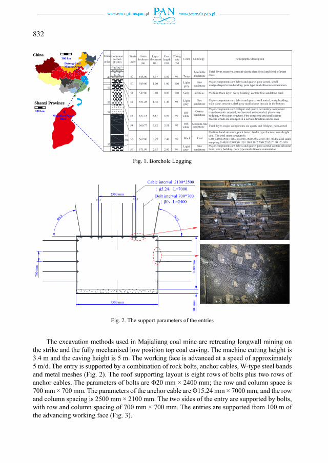
The average coal thickness of 14201 longwall face in 4# coal seam in Majialiang is 8.29 m. The coal seam contains 3 to 5 dirt bands with a thickness range of 0.1 to 0.8 m and an average thickness of 0.5 m. The coal seam depth is 525 to 650 m. Fig. 1 shows the stratified coal and rock seam columnar section, which was explored by drilling a borehole with a diameter of 73 mm in the roof. The intermediate roof primarily consists of medium sandstone, packsand, and kaolin mudstone. The material in the roof primarily consists of medium and coarse sandstone. Besides, the major minerals in the roof are quartz and feldspar. The roof also contains melanocratic minerals and other thick layer structures with medium hardness. The east of the 14201 working face is the 14101 working face, the north of the 14201 is the +665 main roadway, and the west is the unmined 14202 working face. The 14202 auxiliary transporting entry is an entry heads adjacent to the advancing coal face with a coal pillar width of 19.5 m. Both the 14202 auxiliary transporting entry and the 14201-transportation entry have a rectangular cross-section with net width and height of 5.5 m and 3.6 m respectively. The central distance between the cross-section of the two entries is 25 m.
832
Datong Coal Mining Area
300 km China
180 km
Shanxi Province
Majialiang Coal Mine
Medium thick layer, wavy bedding, contain fine sandstone bandsiltstone0.800.8051 549.80
551.28
557.15
560.77
569.06
571.99
coal
+ +
55
54
52
53
54
55
56
1.40
5.69
3.51
7.46
2.80
1.48
5.87
3.62
8.29
2.93
Medium-fine
Coal
Major components are debris and quartz, poor-sorted, contain siltstoneband, wavy bedding, pore type mud siliceous cementation
Thick layer, major components are quartz and feldspar, poor-sorted
Major components are feldspar and quartz, secondary componentis melanocratic mineral, well-sorted, sub-rounded, plate crossbedding, with scour structure. Fine sandstone and argillaceousbreccia which are arranged in a certain direction can be seen
Major components are debris and quartz, well sorted, wavy bedding,with scour structure, dark grey argillaceous breccia in the bottom
Medium band structure, pitch luster, ladder type fracture, semi-brightcoal. The coal seam structure is:0.50(0.10)0.90(0.10)1.36(0.10)3.00(0.25)2.27(0.15)1.00,the coal seamsampling:0.40(0.10)0.80(0.10)1.10(0.10)2.70(0.25)2.07 0.15)1.00
548.00
549.00
++ +
++++
+++ +
52
49 49
50
3.80
1.00
3.97
1.00 Fine
Kaolinitic
Major components are debris and quartz, poor sorted, smallwedge-shaped cross-bedding, pore type mud siliceous cementation
Thick layer, massive, contain clastic plant fossil and fossil of plantroots
Strata
order
Columnar Strata
order
GrossLithology
(m)
Layer
(m)(1:200) (m)Petrographic description
Grey
Off-
grey
Black
Light
Taupe
Color
Light
(%)
Core length
Coring rate
100
95
97
97
90
96
96
100
53
+ ++ +
+ ++ +
+
+
section
4#
thickness thickness
grey
mudstone
sandstone
greyLight
white
Off-white
sandstone
Finesandstone
Coarsesandstone
Finesandstone
Fig. 1. Borehole Logging
700
mm
80¡ã
2500 mm
5500 mm
Cable inte¦ μ15.Bolt i
¦
80¡ã
erval 2100*2500.24 L=7000interval 700*700μ20 L=2400
3600
mm
0
030
0 m
m
Fig. 2. The support parameters of the entries
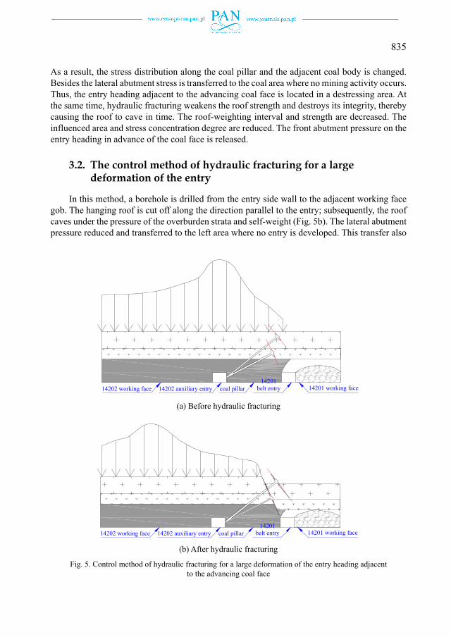
The excavation methods used in Majialiang coal mine are retreating longwall mining on the strike and the fully mechanised low position top coal caving. The machine cutting height is 3.4 m and the caving height is 5 m. The working face is advanced at a speed of approximately 5 m/d. The entry is supported by a combination of rock bolts, anchor cables, W-type steel bands and metal meshes (Fig. 2). The roof supporting layout is eight rows of bolts plus two rows of anchor cables. The parameters of bolts are Φ20 mm × 2400 mm; the row and column space is 700 mm × 700 mm. The parameters of the anchor cable are Φ15.24 mm × 7000 mm, and the row and column spacing is 2500 mm × 2100 mm. The two sides of the entry are supported by bolts, with row and column spacing of 700 mm × 700 mm. The entries are supported from 100 m of the advancing working face (Fig. 3).

833
2.2. Large deformation of the dynamic pressure of the entry heading adjacent to the advancing coal face
When the hydraulic shields are initially set up in the 14201 working face, the hydraulic pressure in its legs is 28 ~ 30 MPa. When the roof-weighting occurs, the pressure is found to increase up to 38 ~ 40 MPa. The average roof-weighting interval is 30 m. The large coal seam thickness and rotating space in the fissure zone lead to a large roof-weighting interval. The dynamic load factor reaches up to 1.67 when the roof-weighting occurs. However, as one of overburden strata supporting points, the area around the coal wall has a thick soft cushion, which causes the roof breaking line to transfer to the deep solid coal body, thereby resulting in a large influenced range of the abutment pressure. However, the strata behaviour in the advanced support area of the entry is not severe and heavy (Fig. 3). There is no obvious strata behaviour in the entry from the working face to the point 60 m in advance of the working face.
The coal pillar separating different working faces in the Majialiang coal mine is usually de-signed to 19.5 m. During mining the 8.29 m thick coal seam with a hard roof, when the advancing working face meets the entry under excavation, the surrounding rock of the new excavated entry of the next working face deforms obviously and largely (the maximum floor heave is 2.5 m, and the average floor heave is 2.3 m). Traditional optimisation and strengthening support technology cannot improve the stability of the entry and the coal pillar under strong mining stress condition (Fig. 3). For safety reason, the entry must be restored and reinforced frequently during the service year. This process not only increases the costs but also affects the safety production of the coal mine and the succession of the working faces.
1
C
1
1
1
1
1t
A
14201 working face
Coal pillar
14201 transportation
4201 auxiliary entry
14202 working face
14202 transportation
4202 auxiliary entryo the advancing coa
n entry
y
n entry
y(entry heading adjaal face)
B
acent
C
100 m
A
0 m30 m
B C
D
-30 m
D
Gob area
-100 m
E
E
260.
5 m
19.5
m5.
5 m
249.
5 m
Fig. 3. Large deformation of the dynamic pressure of the entry using traditional support methods

834
2.3. Mechanism of the large deformation of the dynamic pressure of the entry heading adjacent to the advancing coal face
In the mining and extraction processes of coal seam (rock mass), the ground pressure redistributes and forms abutment pressure in the working face and the surrounding rock mass of the entry. During mining stage, the weight of overburden strata over the gob is supported by the coal wall around the gob area. As a result, advanced abutment pressure forms in front of the working face (Fig. 4). Besides the lateral abutment pressure also forms in the head and tail parts of the working face.
Because the 4# coal seam has a large thickness, both the rotating space in the fissure zone and the roof subsidence are large; thus, the hard roof cannot cave in a timely manner, leading to the high abutment stress concentration. The thick coal seam causes the roof breaking line to move forward, thereby resulting in a large hanging roof area and a large area influenced by the front abutment pressure. Along the dip direction of the working face, outside of the 14201 transportation entry is 19.5 m of coal pillar. According to the strata behaviour law of a thick coal seam by using the fully mechanised top coal caving method, the entry heading of the advancing coal face is located in the lateral abutment pressure-concentrated area. Besides, the dynamic and static loads are very large. Under the effect of front and lateral abutment pressure, 14202 auxiliary entry deforms largely and significantly.
C
Advancingg direction
A – Pre-existing rock stress zone; B – Stress disturbance zone; C – Stress stabilized zone
Fig. 4. Stress distribution in a coal pillar before and after the working face (Qian et al., 2010)
3. The control principle for large deformation of the dynamic pressure at the entry heading adjacent to the advancing coal face
3.1. Weaken the influence of the dynamic pressure adjacent to the gob by hydraulic fracturing
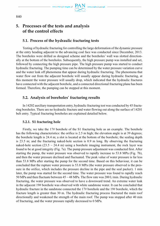
Using directional hydraulic fracturing to cut off the roof above coal pillar (Fig. 5) will changes the supporting structure of the coal pillar and the solid coal body to the upper strata.
835
As a result, the stress distribution along the coal pillar and the adjacent coal body is changed. Besides the lateral abutment stress is transferred to the coal area where no mining activity occurs. Thus, the entry heading adjacent to the advancing coal face is located in a destressing area. At the same time, hydraulic fracturing weakens the roof strength and destroys its integrity, thereby causing the roof to cave in time. The roof-weighting interval and strength are decreased. The influenced area and stress concentration degree are reduced. The front abutment pressure on the entry heading in advance of the coal face is released.
3.2. The control method of hydraulic fracturing for a large deformation of the entry
In this method, a borehole is drilled from the entry side wall to the adjacent working face gob. The hanging roof is cut off along the direction parallel to the entry; subsequently, the roof caves under the pressure of the overburden strata and self-weight (Fig. 5b). The lateral abutment pressure reduced and transferred to the left area where no entry is developed. This transfer also
14202 auxiliary entry coal pillar 14201 working face14201
belt entry14202 working face
(a) Before hydraulic fracturing
14202 auxiliary entry coal pillar 14201 working face14201
belt entry14202 working face
(b) After hydraulic fracturing
Fig. 5. Control method of hydraulic fracturing for a large deformation of the entry heading adjacent to the advancing coal face

836
results in the entry to be located in an area where the lateral abutment pressure is destressed. Because the front abutment pressure can move during working face advancing, conducting hy-draulic fracturing in the roof in front of the working face can weaken the roof strength and cause the roof cave in a timely manner by ground pressure. The influenced area decreased, the stress concentration degree of the front abutment pressure reduced, and the effect of front abutment pressure on the entry is released.
Based on above information, the technology of directional hydraulic fracturing in the roof to control large deformation is proposed. In this approach, boreholes are drilled in the entry or high-level drainage entry to the specific hard rock strata above the working face. Then, hydraulic fracturing is conducted. By using hydraulic-cutting or slotting at the bottom of borehole, the fracture is extended directionally, which causes the hard roof is cut off as planned (Huang et al., 2017; Huang et al. 2018). In addition, the coal and rock strata are simultaneously wetted and softened, resulting in the surrounding stress to be transferred to an unconcerned area and enabling the roof to be caved in a timely manner. This proposed method achieves the goal of controlling the entry deformation via a reduction of surrounding stress.
4. Testing plan
Early stage of field tests indicate that a specific hydraulic fracturing pump with a rated water pressure of 56 MPa and a rated flow of 200 L/min can meet the requirements of hard roof hydraulic fracturing in the Datong mine district.
4.1. Determination of the targeted fracturing rock layer
Based on the roof columnar section, a thick and hard rock stratum is chosen as the hydraulic fracturing target, i.e., the 53# and 54# rock strata above the 14201 working face, consisting of medium-coarse sandstone with an average thickness of 9.49 m and exhibiting hard structure. Hydraulic fracturing was conducted in the 53# and 54# strata.
4.2. The layout and construction of the fracturing boreholes
(1) Boreholes layoutThe boreholes were drilled perpendicular to the side wall in the 14202 auxiliary transport-
ing entry 300 m away from the 14201 working face. The boreholes named S1 were drilled at an elevation angle of 24° toward the 14201 working face. The distance between two adjacent S1 boreholes is 30 m. At 15 m away from S1, boreholes S2 were drilled at an elevation angle of 35°with a borehole spacing of 30 m toward the 14201 working face. Fig. 6ab shows the specific parameters of the boreholes. The layout of the boreholes and the location of the pump station are shown in Fig. 6c.
(2) Boreholes drillingThe boreholes should pass through the coal pillar between the 14201 and 14202 working
faces, where the strata behaviours are strong and the borehole deformation is large. Some borehole deformation should be reserved in advance. Based on the 14201 working face columnar section, two boreholes should be drilled to control the intermediate and the main roof separately. The

837
drilling location of borehole is designed to be 2.5-m high from the entry floor. The calculated drilling length of S1 is 20.5 m, and the length of S2 is 23 m. If the borehole deforms severely during construction, re-drilling the borehole or casing pipe measurements should be used. The borehole section in the coal seam should be drilled using a large diameter bit, and the borehole section in the roof rock should be drilled using a specific bit. Subsequently, directional slotting is conducted at the bottom of the borehole (Huang et al., 2013).
Determining the location of each borehole and numbered sequentially (Fig. 6c). For each borehole drilling, first set up the drilling rig and adjust the angle of the drill pipe, then start the drilling. When the drilling depth reaches the design requirements, retreat the drilling pipe and replace the regular bit with a groove drilling bit to produce a wedge ring groove at the bottom of the borehole.
The boreholes parameters are determined by the 14201 working face columnar section. The parameters of the boreholes at different positions should be revised based on the specific circumstance.
Considering the drilling machine and amount of workload, firstly, the approach can be conducted as above designed. If the result is not as good as expected, the borehole elevation angle and depth can be changed by moving the borehole bottom toward the middle area of the coal pillar. The boreholes can also be used to control the upper rock strata.
A A
14202 auxiliary entry 14201 belt entry
(a) Plan view of the boreholes layout
14202 auxiliary entry
20.5
23
24¡ã35¡ã
8.29
2.5
3.625.87
14201 belt entry
(b) Cross-section view of the boreholes layout from A-A

838
PWC
0.5
1420
2au
xilia
ryen
try2#
1#
3#
4#
5#
6#
7#
8#
9#
10#
11#
PumpWater tankControl box
501420
2 au
xilia
ry e
ntry
Fracturingholes orde
1280
1265
1250
1235
1220
1205
1190
1175
1160
1145
1130
1080
g Footageer (m)
1420
1 be
lt en
try
A
Hig
Anti impact bar
Pum
0.5
gh pressure pipe
Controlbox
Watertank
Pump
r
mp station
(c) Sketch map of the layout of the fracturing boreholes and the pump station
Fig. 6. Hydraulic fracturing scheme

839
4.3. Analysis of the safety technique
4.3.1. The stability of the roof in the advance supporting area
Fracturing boreholes are drilled in the 14202 auxiliary transportation entry toward the ad-vance supporting area of the 14201 belt entry. The radial fractures and the axial fractures that are toward non-working side can be produced in the roof strata using different hydraulic fracturing methods (Zhao et al., 2018). After hydraulic fractures are produced, the roof of the 14201 belt entry is in an overall metastable state. However, it still has a certain amount of self-stability. The rock weight of fracturing section does not completely act on the single hydraulic shield in the advance supporting area.
Using hydraulic fracturing combined with the existence of large size pillars and the pres-sure relief function of the anchor cable holes in the entry, the safety performance of the entry in adjacent working face is improved.
4.3.2. Safeguards for the technique
(1) Pressure relief function of the anchor cable boreholesCurrently, there are many anchor cables and bolts in the entry. Therefore, during the progress
of hydraulic fracturing, the anchor cable boreholes can act as pressure relief holes to limit the extension radius of hydraulic fracture and guarantee the stability of the adjacent entry. In addition, because of the pressure relief holes (anchor cable boreholes) in the roof of advance supporting area, the rock layers of roof within cable length range will not be over broken.
(2) Strict control of the hydraulic fracturing timeDuring hydraulic fracturing, the pump is stopped 2 minutes after an obvious water pressure
decline occurs. Controlling hydraulic fracturing time can control the extension range of hydraulic fracture and the broken degree of the roof.
(3) The possibility of using wide pillars to decrease the hydraulic fracture extending to the roof of the adjacent entry
Currently, the coal pillar width is 19.5 m, which is considered as a large-size coal pillar between two working faces. With the pressure relief function of the anchor cable boreholes and the controlling of fracturing time, hydraulic fracture is inhibited from extending to the roof of the adjacent entry.
(4) Mine pressure observation of the advance supporting areaDuring field testing, the working resistance and inner prop retraction (roof convergence
rate) of the props in advance supporting area is monitored, and the qualitative corresponding relationship between these parameters and the macro cracking of the surface of the entry roof is analysed. At the same time, the adjacent entry is observed and the technical parameters are optimised for the face-end roof caving after hydraulic fracturing.
(5) The characteristics of the hydraulic fracturing monitorRemote real-time monitoring of the water pressure and the flow rate are recorded by us-
ing the hydraulic fracturing monitor. The changes of water pressure and flow rate indicate the propagation of hydraulic fracture. It will provide a benchmark for decision making during hy-draulic fracturing. As a result, the usage of the monitor makes sure that hydraulic fracturing can be safely performed.
840
5. Processes of the tests and analysis of the control effects
5.1. Process of the hydraulic fracturing tests
Testing of hydraulic fracturing for controlling the large deformation of the dynamic pressure at the entry heading adjacent to the advancing coal face was conducted since December, 2013. The boreholes were drilled as designed scheme and the boreholes’ wall was slotted direction-ally at the bottom of the boreholes. Subsequently, the high pressure pump was installed and set, followed by connecting the high pressure pipe. The high pressure pump was started to conduct hydraulic fracturing. The pumping time can be determined by the water pressure variation curve and the water leak off phenomena that appear during hydraulic fracturing. The phenomena that water flow out from the adjacent borehole will usually appear during hydraulic fracturing, at this moment the water pressure will usually drop, which indicated that the hydraulic fractures have connected with the adjacent borehole, and a connected directional fracturing plane has been formed. Therefore, the pumping can be stopped at this moment.
5.2. Analysis of boreholes’ fracturing results
In 14202 auxiliary transportation entry, hydraulic fracturing test was conducted by 45 fractu-ring boreholes. There are no hydraulic fracture and water flowing out along the surface of 14201 belt entry. Typical fracturing boreholes are explained detailed below.
5.2.1. S1 fracturing hole
Firstly, we take the 17# borehole of the S1 fracturing hole as an example. The borehole has the following characteristics: the orifice is 2.5 m high; the elevation angle is at 39 degrees; the borehole length is 24.4 m; a slot is located at the bottom of the borehole; the sealing depth is 23.5 m; and the fracturing naked-hole section is 0.9 m long. By observing the fracturing naked-hole section (23.5 ~ 24.4 m) using a borehole imaging instrument, the rock layer was found to be at good integrity (Fig. 7a). The pump pressure adjustment was conducted first. After starting the pump, the water pressure was observed to rapidly increase to 53.8 MPa (Fig. 7b), and then the water pressure declined and fluctuated. The peak value of water pressure is far less than 53.8 MPa after starting the pump for the second time. Based on this behaviour, it can be concluded that the rupture water pressure is 53.8 MPa (the water pressure observed is the pres-sure in the orifice, which includes the pressure decline in the pipe and the seal packer). 1 min later, the pump was started for the second time. The water pressure was found to rapidly reach 50 MPa and then fluctuate between 45 ~ 48 MPa. The flow rate was 200 L/min. During hydraulic fracturing, the water pressure was observed to have a downward trend. An extreme water leak in the adjacent 19# borehole was observed with white sandstone water. It can be concluded that hydraulic fracture in the sandstone connected the 17# borehole and the 19# borehole, which the fracture length is greater than 30 m. The hydraulic fracturing process fractured the main roof directionally and weakened the strength of the main roof. The pump was stopped after 40 min of fracturing, and the water pressure rapidly decreased to 0 MPa.

841
(a) The fracturing naked-hole section
0 5 10 15 20 25 30 35 40 450
10
20
30
40
50
60
Time (min)
Wat
er p
ress
ure
(MPa
)
(b) Water pressure curve
Fig. 7. Water pressure curve of the S1 fracturing hole
5.2.2. S2 fracturing hole
Secondly, we take the 12# borehole of the S2 fracturing hole as an example. The borehole has the following characteristics: the actual orifice height is 1.9 m; the elevation angle is 32 degrees; the borehole length is 25.1 m; a slot is located at the bottom of the borehole; the sealing depth is 23.2 m; and the fracturing naked-hole section is 1.9 m. After hydraulic fracturing begins, the water pressure was observed to increase rapidly, and the rupture water pressure was observed to be 30.5 MPa (Fig. 8). With the fracture extension, the water pressure declines slowly and fluctuates. After 16 min, the water pressure was observed to increase to 25 MPa suddenly. This increasing may be induced by the hydraulic fracture extending to the cement of the rock layer, crossing the cement and producing a new hydraulic fracture. Subsequently, the water pressure declines slowly and begins to stabilise at 23 MPa. The pump was stopped after 28 min fracturing. The average flow rate monitored was 160 L/min.
During hydraulic fracturing, an extreme water leak occurs in adjacent borehole (13# bore-hole) (Fig. 9a); the water was white water carrying rock fines. Radial fracture was observed in the 12# borehole using the borehole imaging instrument. It can be concluded that hydraulic fracture connected the 13# borehole and the 12# borehole, which the fracture length was approximately 15 m long. Directional hydraulic fracturing connected the main roof and the intermediate roof

842
0 5 10 15 20 25 300
5
10
15
20
25
30
35
Time (min)
Wat
er p
ress
ure
(MPa
)
Fig. 8. Water pressure curve of the S2 fracturing hole
and weakened the integrity of roof. Two axial fractures, which were connected at the bottom of borehole, were also observed by using the borehole imaging instrument. In addition, water leakage was found to occur in the coal wall, anchor cable and anchor bolts near the fracturing hole during fracturing. Obviously, under the cutting function of the two directions of fracture, the integrity of the hard medium coarse sandstone was broken effectively.
In conclusion, the directional hydraulic fracturing process fractures the rock layer of roof, with the fracture length is longer than 15 m. In addition, hydraulic fracturing will produces pri-mary cracks and new fractures. Those man-made discontinuities will connect with each other. The propagation of the radial and axial fracture breaks the integrity of the rock layer in roof effectively.
The fracture length is mainly affected by pumping rate and pumping time, and it usually increase with the pumping rate or pumping time increase during hydraulic fracturing. For hydraulic fracturing with a constant pumping rate, the fracture length no longer increase after the pumping reaching a certain time, that is, there is a limit pumping time for hydraulic fracture propagation. When hydraulic fracturing performed in underground coal mines, the pumping time is usually longer than this limit time to ensure that the hydraulic fractures can propagate far enough. Based on prior construction experience, when the pumping rate is 200 L/min, the fractures no longer propagate after 15 ~ 20 mins of pumping, so the pumping time of hydraulic fracturing is usually longer than 20 mins. In this study, the pumping time is longer than 25 mins, so it is longer enough for hydraulic fractures propagating.
5.3. Control effects of the large deformation of the entry heading adjacent to the advancing coal face
5.3.1. Mine pressure, top coal and roof caving in the working face
After hydraulic fracturing, in the advance supporting area along the belt entry of the 14201 working face, the mine pressure increased slightly. The prop pressure of the hydraulic shield in

843
the working face was 28 ~ 35 MPa and increased to 38 ~ 40 MPa while weighting. The aver-age weighting interval decreased to 25 m. After fracturing completed, the prop pressure of the hydraulic shield increased by 5 MPa and the average weighting interval decreased by 5 m. Top coal and roof caved in time. Hydraulic fracturing improved the cavability of roof effectively.
5.3.2. Surface deformation monitor of the entry heading adjacent to the advancing coal face
The comparison of the entry deformation in the section without fracturing and with fractur-ing is shown in Fig. 10. The control effect of hydraulic fracturing is obvious.
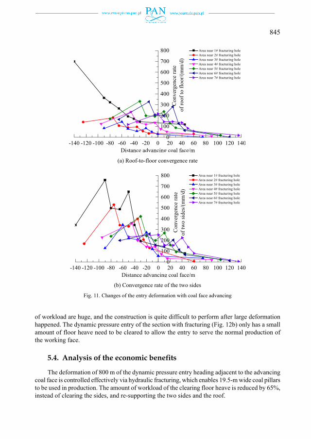
Roof-to-floor convergence and two-sidewalls convergence monitor stations were set near the fracturing boreholes to monitor the surface deformation of the entry (Fig. 11). Selected monitor-ing data from the 1# to 7# fracturing holes were analysed.
Radial fraacture
(a) Radial fracture
Axial fraccture
(b) Axial fracture
Fig. 9. Morphology of fracture on the wall of the S2 fracturing hole

844
Fig. 11 illustrates that the severe deformation section of the entry heading adjacent to the advancing coal face is located in the range of 60 m in advance of the working face and 90 m lagging behind the working face. Before fracturing, the range is 70 m in advance of the work-ing face and 135 m lagging behind the working face. Hydraulic fracturing decreases the severe deformation range effectively.
In the entry heading adjacent to the advancing coal face, 30 m behind the adjacent working face, the roof-to-floor convergence rate increased clearly near the 1# and 2# fracturing holes. When dynamic pressure arrives, the floor heave and the roof subsidence were observed to change from increasing sharply to becoming stable. The reason why this behaviour occurred is that the 1# and 2# fracturing holes are the beginning sections of the hydraulic fracturing section and there is a boundary effect. By comparing the convergence rates of the 3#, 4#, 5#, 6# and 7# fracturing holes to those of the 1# and 2# holes, hydraulic fracturing has a significant effect on decreasing the deformation rate of the entry.
After fracturing, the maximum roof-to-floor convergence rate is approximately 758 mm/d. The convergence is approximately 1.2 m, and the maximum floor heave is approximately 0.9 m. The maximum convergence rate of the two sidewalls is approximately 699 mm/d with the maximum convergence of approximately 0.87 m. After conversion, the average convergence of the two sidewalls is approximately 0.4 m, and the average of maximum floor heave is ap-proximately 0.7 m, which is much smaller than the convergence of the dynamic pressure entry without fracturing (maximum floor heave is 2.5 m, and the average of maximum floor heave is approximately 2.3 m).
In conclusion, after hydraulic fracturing, the large deformation range of the entry heading adjacent to the advancing coal face is reduced by 45 m; the average floor heave is reduced by 70%; and the average convergence of the entry’s two sidewalls is reduced by 65%. The deforma-tion of the dynamic pressure entry is effectively controlled.
5.3.3. Comparison of the floor heave clearing and sidewall clearing
The dynamic pressure entry of the section without fracturing (Fig. 12a) must clear the floor heave several times. It also needs to clear the sidewalls and re-support the entry. Those amounts
(a) Section without fracturing (b) Section with fracturing
Fig. 10. Comparison of the final deformation of the entry before and after hydraulic fracturing
845
of workload are huge, and the construction is quite difficult to perform after large deformation happened. The dynamic pressure entry of the section with fracturing (Fig. 12b) only has a small amount of floor heave need to be cleared to allow the entry to serve the normal production of the working face.
5.4. Analysis of the economic benefits
The deformation of 800 m of the dynamic pressure entry heading adjacent to the advancing coal face is controlled effectively via hydraulic fracturing, which enables 19.5-m wide coal pillars to be used in production. The amount of workload of the clearing floor heave is reduced by 65%, instead of clearing the sides, and re-supporting the two sides and the roof.
-140 -120 -100 -80 -60 -40 -20 0 20 40 60 80 100 120 1400
100
200
300
400
500
600
700
800
Distance advancing coal face/m
Area near 1# fracturing hole Area near 2# fracturing hole Area near 3# fracturing hole Area near 4# fracturing hole Area near 5# fracturing hole Area near 6# fracturing hole Area near 7# fracturing hole
Con
verg
ence
rate
of
roof
to fl
oor/(
mm
/d)
(a) Roof-to-floor convergence rate
-140 -120 -100 -80 -60 -40 -20 0 20 40 60 80 100 120 1400
100
200
300
400
500
600
700
800
Distance advancing coal face/m
Area near 1# fracturing hole Area near 2# fracturing hole Area near 3# fracturing hole Area near 4# fracturing hole Area near 5# fracturing hole Area near 6# fracturing hole Area near 7# fracturing hole
Con
verg
ence
rate
of tw
o si
des/
(mm
/d)
(b) Convergence rate of the two sides
Fig. 11. Changes of the entry deformation with coal face advancing

846
Currently, 19.5-m wide coal pillars are used in the 8000 m entries in the Majialiang coal mine. The reduction of implicit cost is 1 ~ 4 thousand dollars per meter per entry. This technique has great practical value, and will provide obvious economic and social benefits.
6. Conclusions
(1) When longwall mining method is utilised in an underground coal mine, due to difficul-ties in the success of tunnelling or double entry layout, it is always observed that the entry of the adjacent working face has been tunnelled before the working face is mined, or the entry of the adjacent working face is being tunnelled while the working face is being mined. Influenced by the dynamic pressure of front abutment pressure and lateral abutment pressure, large deformation of the surrounding rock occurs around the advancing working face in the mining entry.
(2) To control large deformation of the dynamic pressure entry heading of the advancing coal face, hydraulic fracturing is conducted via drilling boreholes in the entry or in high drainage entry to a certain rock layer over the adjacent working face. Hydraulic cutting seam or slotting in the bottom of drill-holes are also adopted in advance to lead the directional extension of hydraulic fracture, to cut off the hard roof above the coal-pillar directionally, to break the roof’s integrity,
(a) Section without fracturing
(b) Section with fracturing
Fig. 12. Comparison of the floor heave clearing before and after hydraulic fracturing

847
and to wet and soften the coal or rock layer. The combined effects of directional fracturing, wet-ting and softening, cause the roof to cave in time, decrease the front abutment pressure and the lateral abutment pressure in entry heading of the advancing coal face. It also transfers the stress, decreases the influence of dynamic pressure, and improves the distribution of abutment pressure in the coal-pillar.
(3) By using a fracturing pump with a rated flow of 200 L/min and perform hydraulic fracturing for an enough longer time, the fracture propagation length of one borehole is not less than 15 m, and the controlling range is greater than 30 m.
(4) The field tests at the Majialiang coal mine indicated that after hydraulic fracturing, the severe deformation range of entry heading of the adjacent advancing coal face is reduced by 45 m; the average floor heave is reduced by 70%; and the average convergence of the entry’s two sides is reduced by 65%. Directional hydraulic fracturing of the hard roof has a better per-formance on controlling the large deformation of the dynamic pressure entry heading adjacent to the advancing coal face. It will improve the safety production and the normal success of the working faces. It also creates economic benefits of saving approximately 1 ~ 4 thousand dollars per meter of entry.
Acknowledgments
Financial support for this work, provided by the National Key Research and Development Program of China (No. 2017YFC0603001), the National Natural Science Foundation of China (No. 51774272), and the Fundamental Research Funds for the Central Universities (China University of Mining and Technology) (No. 2015XKZD04), is gratefully acknowledged.
References
Bai J.B., Shen W.L., Guo G.L., 2015. Roof deformation, failure characteristics, and preventive techniques of gob-side entry driving heading adjacent to the advancing working face. Rock Mech. Rock Eng. 48, 2447-2458.
Bousbia N., Messast S., 2015. Numerical modelling of two parallel tunnels interaction using three dimensional Finite Elements Method. Geomech. Eng. 9, 6, 775-791.
Chemov O.I., Barsukov I.I., Posokhov G.E., 1997. Oriented hydraulic fracturing of a mass of rocks enclosing the “in-ternational” diamond pipe. J. Min. Sci. 33, 6, 582-586.
Chen R.P., Meng F.Y., Li Z.C., Ye Y.H., Ye J.N., 2016. Investigation of response of metro tunnels due to adjacent large excavation and protective measures in soft soils. Tunn. Undergr. Space. Technol. 58, 224-235.
Dong C.Y., Pater C.J., 2002. Numerical modelling of crack reorientation and link-up. Adv. Eng. Softw. 33, 577-587.Hou C.J., Li X.H., 2001. Stability principle of big and small structures of rock surrounding roadway driven along goaf
in fully mechanized top coal caving face. J. Chin. Coal. Soc. 26, 1, 1-7.Han C.L., Zhang N., Li B.Y., Si G.Y., Zheng X.G., 2015. Pressure relief and structure stability mechanism of hard roof
for gob-side entry retaining. J. Cent. South Univ. 22, 4445-4455.Huang B.X., Cheng Q.Y., Liu C.Y., Wei M.T., Fu J.F., 2011. Hydraulic fracturing theory of coal-rock mass and its
technical framework. J. Min. Saf. Eng. 28, 2, 167-173.Huang B.X., Cheng Q.Y., Zhao X.L, Xue W.C., Malcolm S., 2018. Using hydraulic fracturing to control caving of the
hanging roof during the initial mining stages in a longwall coal mine: a case study. Arab. J. Geosci. 11, 20, 603.Huang B.X., Chen S.L., Zhao X.L., 2017. Hydraulic fracturing stress transfer methods to control the strong strata
behaviours in gob-side gateroads of longwall mines. Arab. J. Geosci. 10, 11, 236

848
Huang B.X., Huang C.M., Cheng Q.Y., Huang C.H., Xue W.C. 2012. Hydraulic fracturing technology for improving permeability in gas-bearing coal seams in underground coal mines. J. S. Afr. Inst. Min. Metall. 112, 6, 485-495.
Huang B.X., Wang Y.Z., 2015. Field investigation on crack propagation of directional hydraulic fracturing in hard roof. J. Chin. Coal Soc. 40, 9, 2002-2008.
Huang B.X., Yu B., Feng F., Li Z., Wang Y.Z., Liu J.R., 2013. Field experimental investigation on directional hydraulic fracturing for hard roof in Tashan coal mine. J. Coal Sci. Eng. 19, 2, 153-159.
Hubbert M.K., Willis D.G., 1957. Mechanics of Hydraulic Fracturing. Transactions SPE AIME. 210, 153-168.Huang X., Schweiger H.F., Huang H., 2011. Influence of deep excavations on nearby existing tunnels. Int. J. Geomech.
13, 170-180.Jeffrey R.G., Chen Z., Zhang X. Bunger A.P., Mills K.W., 2014. Measurement and analysis of full-scale hydraulic frac-
ture initiation and fracture reorientation. Presented at the 48th US Rock Mechanics / Geomechanics Symposium, ARMA, Minneapolis, pp. 1-11
Jeffrey R.G., Mills K.W., 2000. Hydraulic fracturing applied to inducing longwall coal mine goaf falls. In: 4th North American rock mechanics symposium. Seattle, 423-430
Konopko W., Kabiesz J., Merta G., 1997. Directional hydraulic fracturing and the possibilities of its utilization. Prace Naukowe GIG. 824, 1-33.
Li X.B., Cao W.Z., Tao M., Zhou Z.L., Chen Z.H., 2016. Influence of unloading disturbance on adjacent tunnels. Int. J. Rock Mech. Min. Sci. 84, 10-24.
Liang R.Z., Xia T.D., Huang M.S., Lin C.G., 2017. Simplified analytical method for evaluating the effects of adjacent excavation on shield tunnel considering the shearing effect. Comput. Geotech. 81, 167-187.
Liang R.Z., Xia T.D., Hong Y., Yu F., 2016. Effects of above-crossing tunnelling on the existing shield tunnels. Tunn. Undergr. Space Technol. 58, 159-176.
Liu G.B., Huang P., Shi J.W., Ng C.W.W., 2016. Performance of a deep excavation and its effect on adjacent tunnels in shanghai soft clay. J. Perform Constr. Facil. 30, 6, 04016041.
Matsui K., Shimada H., Anzwar H.Z., 1999. Acceleration of massive roof caving in a longwall gob using a hydraulic fracturing. In: 4th international symposium on mining science and technology. Beijing, 43-46.
Qian M.G., Shi P.W., Xu J.L., 2010. Mine stress and strata control, Xuzhou: China University of Mining and Techno-logy Press.
Van A.A., Jeffrey R.G., 2000. Hydraulic fracturing as a cave inducement technique at Northparkes mines. In: Proceed-ings of MASSMIN 2000 conference. Brisbane, 165-172.
Yarushina V.M., Bercovici D., Oristaglio M.L., 2013. Rock deformation models and fluid leak-off in hydraulic fracturing. Geophys. J. Int. 194, 1514-1526.
Zhang H.B., Chen J.J., ASCE A.M. Fan F., Wang J.H., 2017. Deformation monitoring and performance analysis on the shield tunnel influenced by adjacent deep excavations. J. Aerosp. Eng. 30, 2, B4015002.
Zhang J.F., Chen J.J., Wang J.H. Wang J.H., Zhu Y.F., 2013. Prediction of tunnel displacement induced by adjacent excavation in soft soil. Tunn. Undergr. Space. Technol. 36, 24-33.
Zhang N., Li X.H., Gao M.S., 2004. Pretensioned support of roadway driven along next gob and heading adajacent advancing coal face and its application. Chin. J. Rock Mech. Eng. 23, 12, 2100-2105.
Zhang Z.G., Huang M.S., Wang W.D., 2013. Evaluation of deformation response for adjacent tunnels due to soil unload-ing in excavation engineering. Tunn. Undergr. Space Technol. 38, 244-253.
Zheng G., Du Y.M., Cheng X.S., Wang F.J., 2017. Characteristics and prediction methods for tunnel deformations induced by excavations. Geomech. Eng. 12, 3, 361-397.
Zhao X.L., Huang B.X., Wang Z., 2018. Experimental Investigation on the Basic Law of Directional Hydraulic Fracturing Controlled by the Dense Linear Multi-Drilling Holes. Rock Mech. Rock Eng. 51, 6, 1739-1754.