ARC FLASH STUDIES AND SOLUTIONS
57
1 1 © 2009 Eaton Corporation. All rights reserved. ARC FLASH STUDIES AND SOLUTIONS Presenter: • Matthew Mullins • Power Systems Engineer • [email protected] • Office: 954-571-8282 x23 • Cell: 412-760-9981 Oct 16, 2012
Transcript of ARC FLASH STUDIES AND SOLUTIONS

1 1© 2009 Eaton Corporation. All rights reserved.
ARC FLASH STUDIES AND SOLUTIONS
Presenter: • Matthew Mullins• Power Systems Engineer• [email protected]• Office: 954-571-8282 x23• Cell: 412-760-9981
Oct 16, 2012
2 2© 2009 Eaton Corporation. All rights reserved.
PRESENTATION OVERVIEW
• What is Arc Flash?• Review of Standards: Enforcement & Compliance• Arc Flash Study Complete – What Now?• Practical Methods for Reducing Arc Flash Hazards

3 3© 2009 Eaton Corporation. All rights reserved.
WHAT IS ARC FLASH?
NFPA 70E–2012 Article 100. Arc Flash Hazard.• A dangerous condition associated with the possible
release of energy caused by an electric arc.• Informational Note No. 1: An arc flash hazard may exist when
energized electrical conductors or circuit parts are exposed or when they are within equipment in a guarded or enclosed condition, provided a person is interacting with the equipment in such a manner that could cause an electric arc. Under normal operating conditions, enclosed energized equipment that has been properly installed and maintained is not likely to pose an arc flash hazard.
• Informational Note No. 2: See Table 130.7(C)(15)(a) and Table 130.7(C)(15)(b) for examples of activities that could pose an arc flash hazard.
4 4© 2009 Eaton Corporation. All rights reserved.
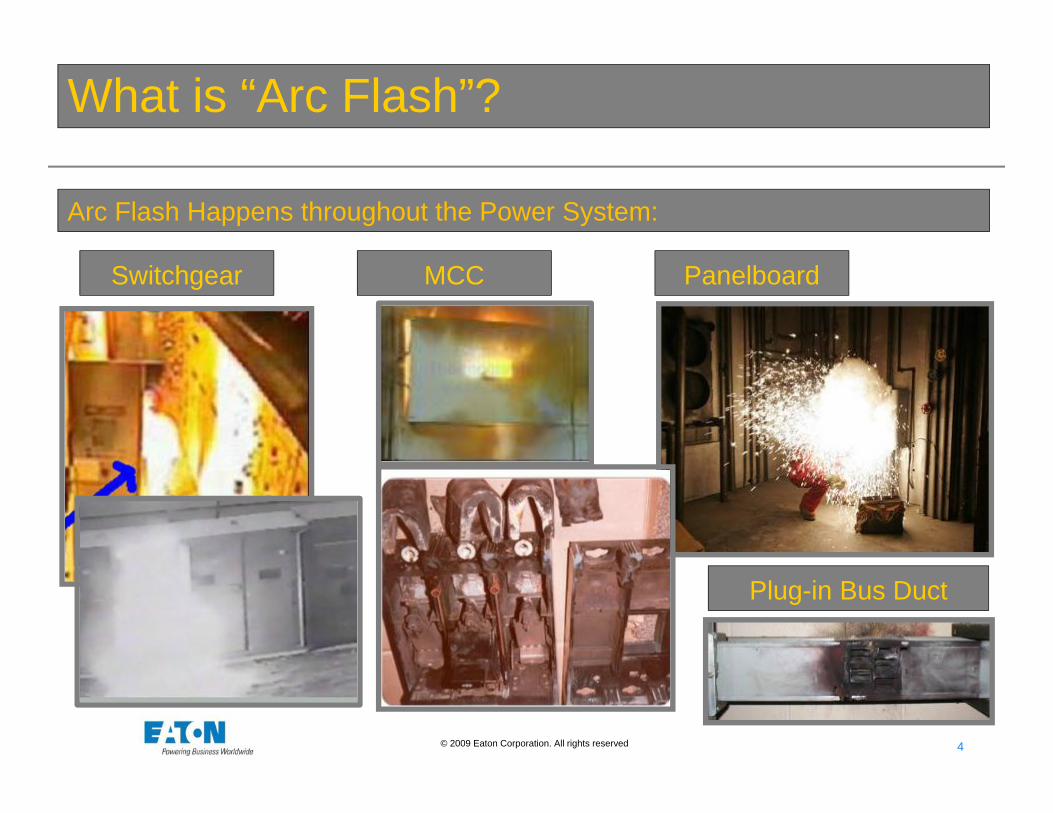
What is “Arc Flash”?
Arc Flash Happens throughout the Power System:
Switchgear MCC Panelboard
Plug-in Bus Duct

5 5© 2009 Eaton Corporation. All rights reserved.
Standards Covering Arc Flash
• National Fire Protection Agency (NFPA)• NFPA 70-2011 National Electric Code (NEC)• NFPA 70E-2012 Standard for Electrical Safety in the
Workplace
• Occupational Safety and Health Administration (OSHA)• OSHA 29 CFR Part 1910
• Institute of Electrical and Electronics Engineers (IEEE) • C2-2007 National Electric Safety Code (NESC)• 1584-2002 Guide for Performing Arc Flash Hazard Calculations

6 6© 2009 Eaton Corporation. All rights reserved.
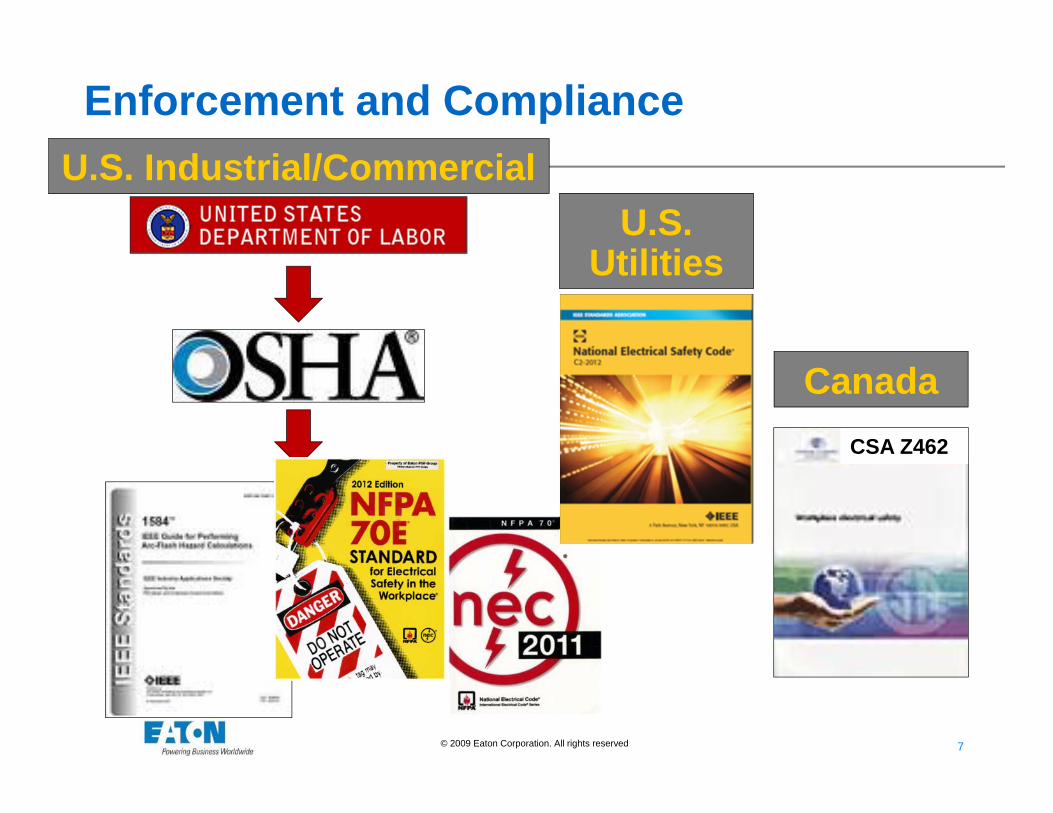
Review of Standards: Enforcement and Compliance
7 7© 2009 Eaton Corporation. All rights reserved.
Enforcement and ComplianceU.S. Industrial/Commercial
U.S. Utilities
CanadaCSA Z462
8 8© 2009 Eaton Corporation. All rights reserved.
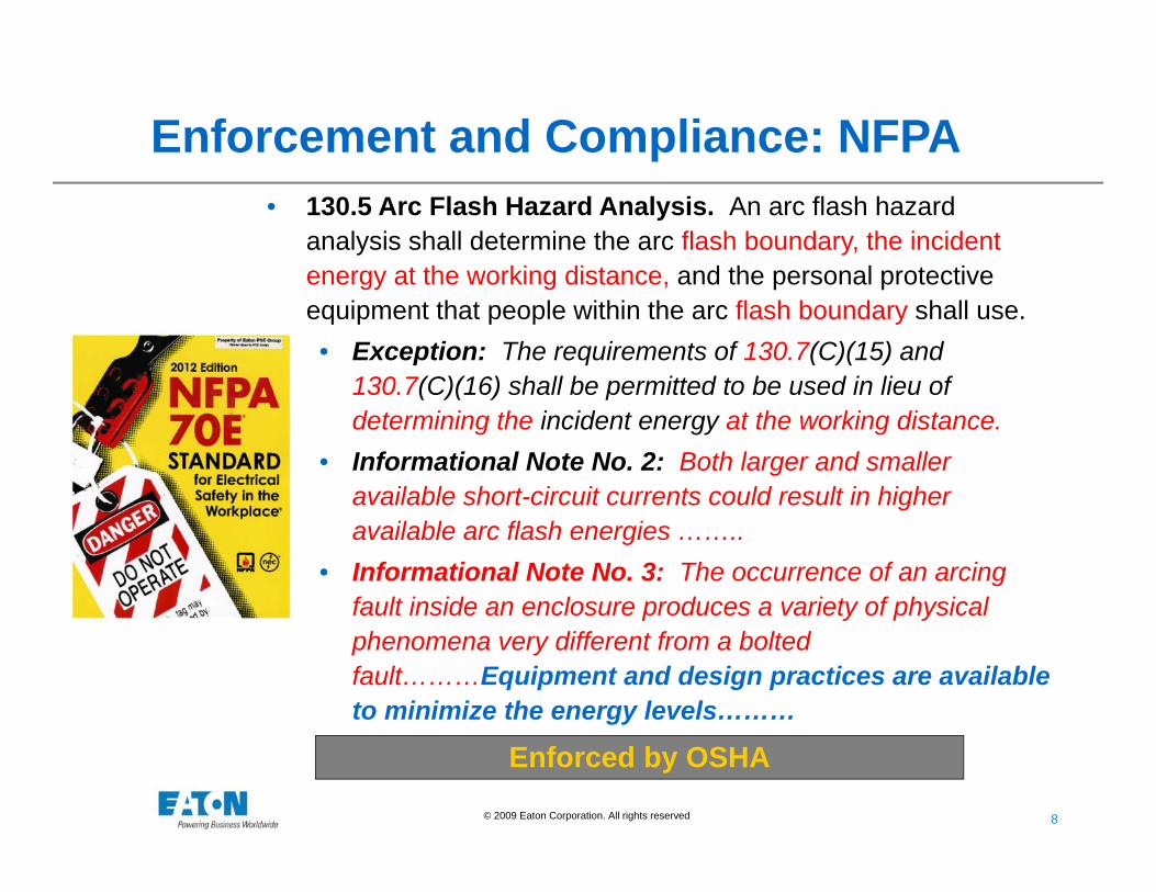
• 130.5 Arc Flash Hazard Analysis. An arc flash hazard analysis shall determine the arc flash boundary, the incident energy at the working distance, and the personal protective equipment that people within the arc flash boundary shall use.• Exception: The requirements of 130.7(C)(15) and
130.7(C)(16) shall be permitted to be used in lieu of determining the incident energy at the working distance.
• Informational Note No. 2: Both larger and smaller available short-circuit currents could result in higher available arc flash energies ……..
• Informational Note No. 3: The occurrence of an arcing fault inside an enclosure produces a variety of physical phenomena very different from a bolted fault………Equipment and design practices are available to minimize the energy levels………
Enforced by OSHA
Enforcement and Compliance: NFPA

9 9© 2009 Eaton Corporation. All rights reserved.
Enforcement and Compliance: NFPA• 130.5(C) Equipment Labeling. Electrical equipment
such as switchboards, panelboards, industrial control panels, meter socket enclosures, and motor control centers that are in other than dwelling units, and are likely to require examination, adjustment, servicing, or maintenance while energized, shall be field marked with a label containing all the following information:
• (1) At least one of the following:• a. Available incident energy and the corresponding working
distance• b. Minimum arc rating of clothing• c. Required level of PPE• d. Highest Hazard/Risk Category (HRC) for the equipment
• (2) Nominal system voltage• (3) Arc flash boundary

© 2010 Eaton Corporation. All rights reserved.
Arc Flash Study Analysis

11 11© 2009 Eaton Corporation. All rights reserved.
Three Main Factors Affecting Incident Energy and Arc Flash
Skin damage will occur based on the intensity of theheat generated by an electrical arc accident. The heatreaching the skin of the worker is dependent on thefollowing three factors:
Main Factors Affecting Arc Flash:• Power of the arc at the arc location• Distance of the worker to the arc• Time duration of the arc exposure

12 12© 2009 Eaton Corporation. All rights reserved.
IEEE Arc Flash Analysis Steps
• Step 1: Collect existing oneline diagrams and power system data• Step 2: Determine the power system’s modes of operation• Step 3: Determine the bolted fault currents• Step 4: Determine the arc fault currents• Step 5: From the protective device characteristics, find the arcing
duration• Step 6: Record system voltages and equipment classes• Step 7: Determine working distances• Step 8: Determine incident energy for each work location in the
study• Step 9: Determine the flash-protection boundary for each work
location in the study

13 13© 2009 Eaton Corporation. All rights reserved.
Additional Arc Flash Analysis Steps
• Step 10: Examine all “unacceptable” locations• Step 11: Determine methods to reduce the incident energy at
these locations• Step 12: Implement arc flash reduction solutions• Step 13: Re-run the arc flash analysis taking the solutions into
account• Step 14: Print and install arc flash hazard warning labels• Step 15: Train all workers who will work on or near energized
equipment

14 14© 2009 Eaton Corporation. All rights reserved.
Arc Flash Study Complete – What Now?• You get Arc Flash Analysis That Looks Like This!
Bus NameDevice Name Bus kV
Bus Bolted
Fault kA
Device Bolted
Fault kA
Device Arcing
Fault kA
Trip Time sec.
Bkr. Opening
sec.GND Equip
Gap mm
AF Boundary
in.
Working Distance
in.
Incident Energy cal/cm2
BUS-50CP1 R-CP1 0.440 48.23 38.65 17.01 0.725 0.05 No SWG 32 260 24 40.0
BUS-50CP2 R-CP2 0.440 47.7 38.92 17.16 0.753 0.05 No SWG 32 267 24 41.6
BUS-50FD1 R-FD1 0.440 69.57 63.15 25.92 1.95 0.05 No SWG 32 652 24 154.7
BUS-50FD2 R-FD2 0.440 73.9 62.14 25.22 1.95 0.05 No SWG 32 648 24 153.5
BUS-50FD3 R-FD3 0.440 74.89 63.28 25.62 1.95 0.05 No SWG 32 654 24 155.5
BUS-50FD4 R-FD4 0.440 69.33 62.9 25.84 1.95 0.05 No SWG 32 651 24 154.5
BUS-50ID1 R-ID1 0.440 95.76 62.58 24.18 1.95 0.05 No SWG 32 656 24 156.3
BUS-50ID2 R-ID2 0.440 95.19 60.51 23.41 1.95 0.05 No SWG 32 645 24 152.3
BUS-50LP1 50LP1-MAIN 0.208 47.29 41.62 10.59 2 0 No SWG 32 346 24 60.8
BUS-50LP1 (Line Side) R-LP1 0.208 47.29 41.62 10.59 1.95 0.05 No SWG 32 346 24 60.8
BUS-50LP2 50LP2-MAIN 0.208 51.06 41.6 10.33 2 0 No SWG 32 346 24 61.0
BUS-50LP2 (Line Side) R-LP2 0.208 51.06 41.6 10.33 1.95 0.05 No SWG 32 346 24 61.0
BUS-50M1 R-M1 0.440 42.87 38.91 17.51 0.742 0.05 No SWG 32 263 24 40.5
BUS-50M2 R-M2 0.440 42.62 38.65 17.41 0.745 0.05 No SWG 32 262 24 40.5
BUS-50M3 R-M3 0.440 43.13 38.7 17.4 0.746 0.05 No SWG 32 263 24 40.6
BUS-50M4 R-M4 0.440 44.78 39.35 17.56 0.741 0.05 No SWG 32 265 24 41.0
BUS-5EX1 R-5EX1 0.440 79.6 56.53 22.62 1.95 0.05 No SWG 32 616 24 142.4
BUS-5EX2 R-5EX2 0.440 63.37 63.37 26.48 1.95 0.05 No SWG 32 657 24 156.6
15 15© 2009 Eaton Corporation. All rights reserved.
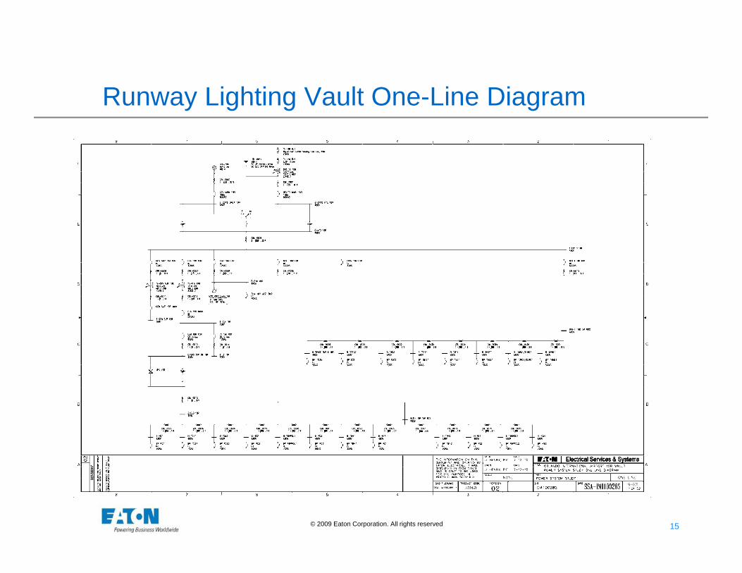
Runway Lighting Vault One-Line Diagram
© 2010 Eaton Corporation. All rights reserved.
Innovative Techniques for Mitigating Arc Flash Exposure

17 17© 2009 Eaton Corporation. All rights reserved.
Things to Consider for Arc Flash Mitigation• Visit Customer Site• Recommend Arc Flash Solutions Study!• Location, Location, Location – will determine your solution
• Physical Location – can equipment be brought in easily?• Environment of Location - tight equip fit, dirty, air quality, etc?• Is there asbestos at Location, watch for in older plants?• Extra Space at Location – to add on main breaker cubicle?• Utility own the incoming transformer?• Most of the time, the AF Incident Energy is calculated to be > 40
cal/cm2 for the secondary side of substation transformers > 750kVA• Condition of Switchgear
• Does it physically need replaced?• Physically, is it worth doing retrofits or retrofills?
• Maintenance of Equipment• How often is equipment worked on energized (daily, weekly, etc)?• How often is equipment tested?

18 18© 2009 Eaton Corporation. All rights reserved.
Eaton Arc Flash Solutions 2012• Engineered Solutions:
Arc Flash Soluions Installation Where Applied AF Lbl Change
Adjust Breaker Settings Existing MV/LV Breaker Relay/Trip Unit Possible
Arc Flash Limiter (AFL) System Retrofit LV Substations, subs with no main sec. bkr. Yes
Arc Flash Reduction Maintenance Switch Retrofit Kits Retrofit LV SWGR Power Breakers Yes
MV A.R.M.S. Using EDR-3000/4000/5000
New EQPT/Retrofit MV SWGR Yes
Fused Switch to Breaker Retro Fills Retrofill LV SWGR Mains Yes
Pringle Switch to Magnum Breaker Retrofit Retrofit LV SWGR Power Breakers Yes
Low Voltage Air Replacement Breakers (LVAR's) Retrofill LV SWGR Power Breakers Yes
Bus Differential Schemes Existing/New EQPT MV/LV SWGR Yes(1)
Barriers for Line/Load - Side Arc Flash Calculations Retrofit Panelboards & Switchboards Yes
EATON ARC FLASH SOLUTIONS QUICK SELECT APPLICATIONS GUIDE
NOTES:(1) AF mitigation may only apply to certain equipment sections or certain maintenance tasks
19 19© 2009 Eaton Corporation. All rights reserved.
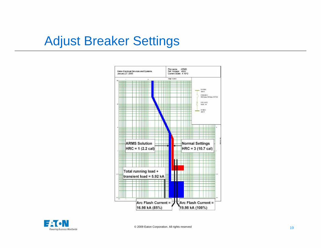
Adjust Breaker Settings

20 20© 2009 Eaton Corporation. All rights reserved.
Eaton Arc Flash Solutions 2012• Engineered Solutions:
Arc Flash Soluions Installation Where Applied AF Lbl Change
Adjust Breaker Settings Existing MV/LV Breaker Relay/Trip Unit Possible
Arc Flash Limiter (AFL) System Retrofit LV Substations, subs with no main sec. bkr. Yes
Arc Flash Reduction Maintenance Switch Retrofit Kits Retrofit LV SWGR Power Breakers Yes
MV A.R.M.S. Using EDR-3000/4000/5000
New EQPT/Retrofit MV SWGR Yes
Fused Switch to Breaker Retro Fills Retrofill LV SWGR Mains Yes
Pringle Switch to Magnum Breaker Retrofit Retrofit LV SWGR Power Breakers Yes
Low Voltage Air Replacement Breakers (LVAR's) Retrofill LV SWGR Power Breakers Yes
Bus Differential Schemes Existing/New EQPT MV/LV SWGR Yes(1)
Barriers for Line/Load - Side Arc Flash Calculations Retrofit Panelboards & Switchboards Yes
EATON ARC FLASH SOLUTIONS QUICK SELECT APPLICATIONS GUIDE
NOTES:(1) AF mitigation may only apply to certain equipment sections or certain maintenance tasks

21 21© 2009 Eaton Corporation. All rights reserved.
Arc Flash Study Complete – What Now?• Example 1: Power Generation
Plant:• Existing Power System - 1 MV GE
Magne-Blast feeding 3 low voltage substations – each w / separate protective relays• Substations are all similar• Incident Energy > 40 cal/cm2 @
the Low Voltage Switchgear (common to all subs)
• Notice 700hp & 800hp motors –must consider for arc flash mitigation (false trips could occur when motor starts W / ARMS engaged)
• Arc Flash Solution for Low Voltage Switchgear (LV SWGR)?
BEFORE
TO OTHERSUBSTATIONS
UTL EXAMPLE13800.0 VSC 3P 16453.0 Amps
CBL-00071 - #4/0, 20 ft
UTL SW
CBL-00091 - #2/0, 150 ft
S
P T-LVSWGR2500.0 kVA13800 / 480V4.78% Z
LVSWGR480VHRC Dangerous!IE = 119.57 Cal/cm^2ANSI Sym 3P LV 63.714 k
CBL-00103 - #500, 265 ft
MTRI-0003700 hp
CBL-00111 - #3000, 100 ft
MTRI-0004800 hp
CBL-00121 - #4000, 10 ft
RLY-MV-BKRGEIAC 51, 5A CTCT 800 / 5 A
MV-BKR
CBL-00141 - #350, 140 ft
MV-BUS13800VANSI Sym 3P LV 16.449 kA
CBL-00221 - #2/0, 135 ft
CBL-00231 - #2/0, 30 ft
RLY-MV-BKR0GEIAC 51, 5A CTCT 800 / 5 A
RLY-MV-BKR1GEIAC 51, 5A CTCT 300 / 5 A
22 22© 2009 Eaton Corporation. All rights reserved.
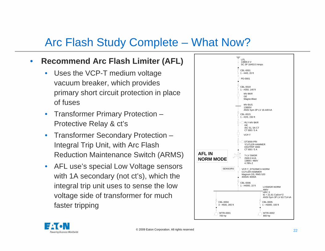
Arc Flash Study Complete – What Now?• Recommend Arc Flash Limiter (AFL)
• Uses the VCP-T medium voltage vacuum breaker, which provides primary short circuit protection in place of fuses
• Transformer Primary Protection –Protective Relay & ct’s
• Transformer Secondary Protection –Integral Trip Unit, with Arc Flash Reduction Maintenance Switch (ARMS)
• AFL use’s special Low Voltage sensors with 1A secondary (not ct’s), which the integral trip unit uses to sense the low voltage side of transformer for much faster tripping
SENSORS
AFL INNORM MODE
UTL13800.0 VSC 3P 16453.0 Amps
CBL-00011 - #4/0, 20 ft
PD-0001
S
PT-LV SWGR2500.0 kVA13800 / 480V4.78% Z
VCP-T
DT3000-PRI*CUTLER-HAMMERDIGITRIP 3000CT 800 / 5 A
LVSWGR-NORM480VHRC 3IE = 21.61 Cal/cm^2ANSI Sym 3P LV 63.714 kA
CBL-00043 - #500, 265 ft
MTRI-0001700 hp
CBL-00051 - #3000, 100 ft
MTRI-0002800 hp
VCP-T_DT520MCV-NORMCUTLER-HAMMERMagnum DS, RMS 5204000A/ 4000A
CBL-00061 - #4000, 10 ft
CBL-00151 - #2/0, 150 ft
RLY-MV-BKRGEIAC 51, 5A CTCT 800 / 5 A
MV-BKRGEMagne-Blast
CBL-00191 - #350, 140 ft
MV-BUS13800VANSI Sym 3P LV 16.449 kA
23 23© 2009 Eaton Corporation. All rights reserved.
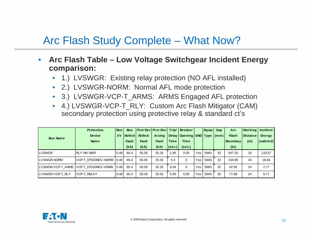
Arc Flash Study Complete – What Now?• Arc Flash Table – Low Voltage Switchgear Incident Energy
comparison:• 1.) LVSWGR: Existing relay protection (NO AFL installed)• 2.) LVSWGR-NORM: Normal AFL mode protection• 3.) LVSWGR-VCP-T_ARMS: ARMS Engaged AFL protection• 4.) LVSWGR-VCP-T_RLY: Custom Arc Flash Mitigator (CAM)
secondary protection using protective relay & standard ct’s
Protective Bus Bus Prot Dev Prot Dev Trip/ Breaker Equip Gap Arc Working IncidentDevice kV Bolted Bolted Arcing Delay Opening GND Type (mm) Flash Distance EnergyName Fault Fault Fault Time Time Boundary (in) (cal/cm2)
(kA) (kA) (kA) (sec.) (sec.) (in)
LVSWGR RLY-MV-BKR 0.48 65.4 55.05 25.33 1.95 0.05 Yes SWG 32 547.20 24 119.57
LVSWGR-NORM VCP-T_DT520MCV-NORM 0.48 65.4 55.05 25.33 0.3 0 Yes SWG 32 154.95 24 18.64
LVSWGR-VCP-T_ARMS VCP-T_DT520MCV-ARMS 0.48 65.4 55.05 25.33 0.04 0 Yes SWG 32 42.50 24 2.77
LVSWGR-VCP-T_RLY VCP-T_RELAY 0.48 65.4 55.05 25.33 0.05 0.05 Yes SWG 32 77.88 24 6.77
Bus Name

24 24© 2009 Eaton Corporation. All rights reserved.
Eaton Arc Flash Solutions 2012• Arc Flash Solution Products:
Arc Flash Soluions Installation Where Applied AF Lbl Change
MV and LV Zone Selective Interlocking Existing/New EQPT PNLBD's,SWBD's,SWGR Yes(1)
MV VCP-T Breakers with Integral ARMS Existing/New EQPT MV SWGR YesMagnum LV Swgr with Integral ARMS Existing/New EQPT New Magnum LV SWGR (ARMS built-in) YesLow Voltage Molded Case Circuit Breakers with ARMS New EQPT/Retrofit New PNLBD's & SWBDS, breaker replacementsNet Work Protector ARMS Existing/New EQPT LV Utility Spot Networks YesMV/LV Remote Pwr Racking/RPR2/Factry Existing/New EQPT Existing MV/LV SWGR Installations NoFlashGard MCCs with Remote Racking Existing/New EQPT New MCC Installation NoFlashGard MCC Bucket Retrofits Existing/New EQPT Existing Eaton and Competitor MCC's NoArc Resistant MV Motor Starters (Ampgard) New EQPT New MV SWGR Installation NoMV Arc Resistant Swgr New EQPT New MV SWGR Installation NoLV Arc Resistant Swgr New EQPT New LV SWGR Installation NoAF Tested Current-Limiting MCCBs New EQPT/Retrofit New PNLBD's & SWBDS, breaker replacements PossibleInfra-Red Windows New EQPT/Retrofit Transformers/SWGR NoInfra-Red Sensors in Hi AF Areas New EQPT/Retrofit Transformers/SWGR No
EZTM Lighting Panelboards New EQPT/Retrofit LV PNLBD's NoMCCB Remote ARMS Control New EQPT/Retrofit LV PNLBD's No
EATON ARC FLASH SOLUTIONS QUICK SELECT APPLICATIONS GUIDE
NOTES:(1) AF mitigation may only apply to certain equipment sections or certain maintenance tasks

25 25© 2009 Eaton Corporation. All rights reserved.
Eaton Arc Flash Solutions 2012• Arc Flash Prevention Solutions:
Arc Flash Soluions Installation Where Applied AF Lbl Change
MV/LV High Resistance Grounding Systems Existing/New MV/LV Substations/SWGR No
Remote Monitoring, Control and Diagnostics Existing/New MV/LV Substations/SWGR No
Ampgard Remote Operators Existing/New MV Ampgard SWGR No
GearGard Continuous Monitoring Existing/New MV/LV Substations/SWGR No
Hi (or Low) Impedance Transformers Existing/New MV/LV Substations No
Insulated Bus in Switchgear New EQPT New MV/LV SWGR Installation No
Current Limiting Reactors Retrofit MV/LV Substations/SWGR Possible
Partial Discharge Systems / InsulGard New EQPT/Retrofit MV/LV Substations/SWGR No
Kirk Key Interlock Systems New EQPT MV/LV Substations/SWGR No
MCC Bucket & Safety Switch Viewing Windows New/Retrofit MCC's No
MCCB Remote Operator New/Retrofit MCCB's No
EATON ARC FLASH SOLUTIONS QUICK SELECT APPLICATIONS GUIDE
NOTES:(1) AF mitigation may only apply to certain equipment sections or certain maintenance tasks

© 2010 Eaton Corporation. All rights reserved.
Label Equipment, Train People, Wear PPE
27 27© 2009 Eaton Corporation. All rights reserved.
Practical Methods for Reducing Arc Flash Hazards
Minimize Risk with Good Safety Practices•De-Energize Equipment versus “Working It Live”unless increased hazards exist or infeasible due todesign or operational limitations.
•Switching remotely (if possible)
Closing and tightening door latches or door boltsbefore operating a switch.Standing to the side and away as much as possibleduring switching operations.

28 28© 2009 Eaton Corporation. All rights reserved.
Train People
• Arc-Flash Safety – 4.0 hours, for electricians, technicians or equipment operators whose employers have already declared them to be "qualified" according to OSHA rules
• Electrical and Arc-Flash Safety – 8.0 hours, for electricians, technicians and equipment operators who are not "qualified" but who might be exposed to arc-flash hazards
• Custom Arc Flash Training – per customer requirements (on site or local), could include performing power system analysis software.

29 29© 2009 Eaton Corporation. All rights reserved.
Wear Personal Protective Equipment (PPE)
• Cumbersome• Hot• Reduces Mobility• Increases Fatique
30 30© 2009 Eaton Corporation. All rights reserved.
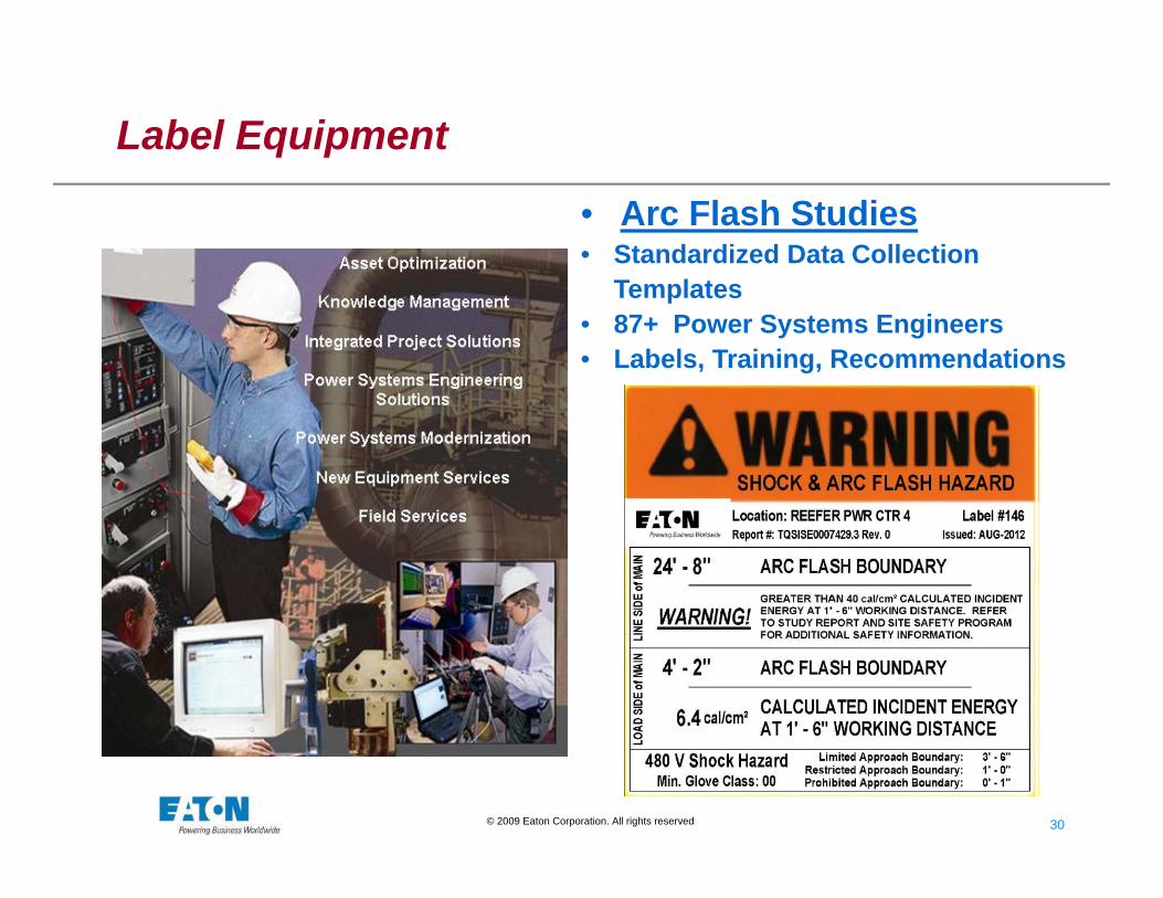
Label Equipment
• Arc Flash Studies• Standardized Data Collection
Templates• 87+ Power Systems Engineers• Labels, Training, Recommendations

© 2010 Eaton Corporation. All rights reserved.
Reduce Available Fault Current(Reduce Incident Energy - but not always the case)
© 2010 Eaton Corporation. All rights reserved.
Faster Clearing Time

34 34© 2009 Eaton Corporation. All rights reserved.
High Speed Clearing
• Bus Differential (87B)—MV or HV• Zone Selective Interlocking – a Control approach /
Form of 87B – MV and LV• Arc Flash Reduction Maintenance Switch (ARMS)
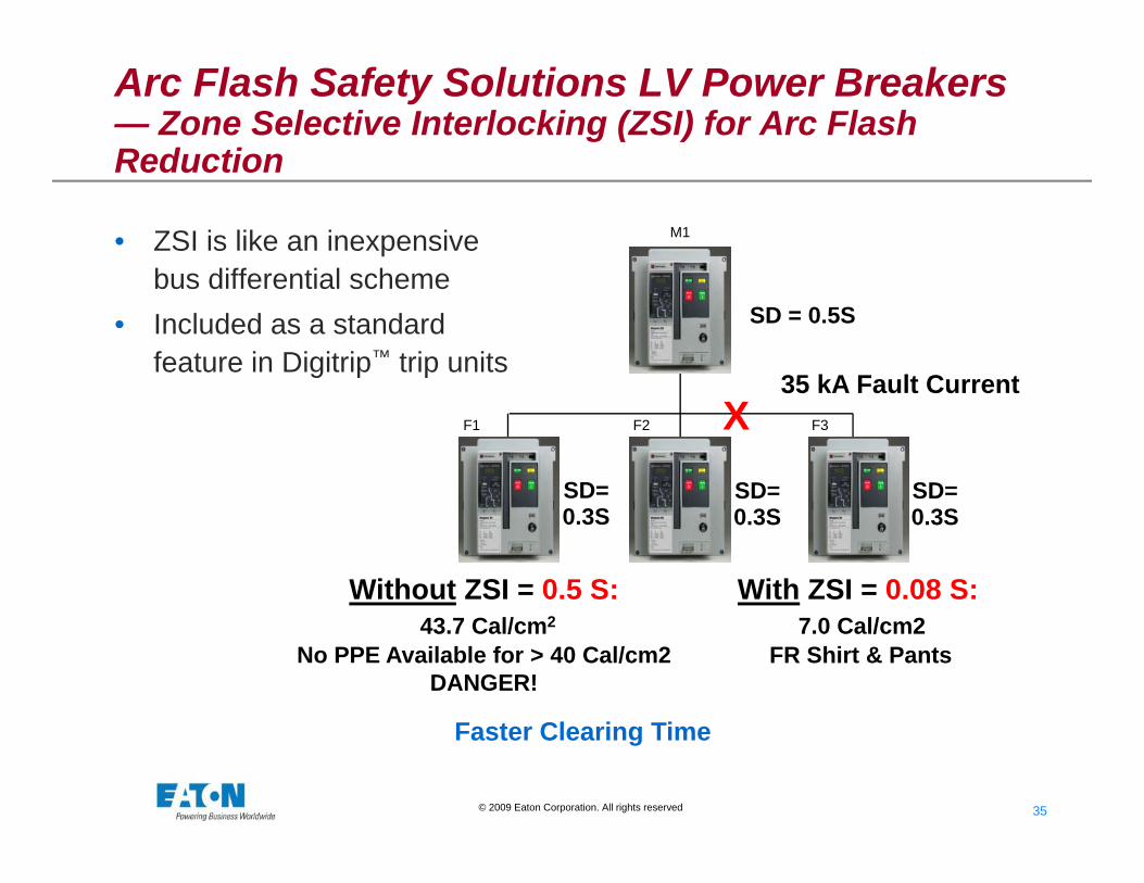
35 35© 2009 Eaton Corporation. All rights reserved.
SD = 0.5S
SD=0.3S
SD=0.3S
SD=0.3S
M1
F1 F2 F3X35 kA Fault Current
Faster Clearing Time
Arc Flash Safety Solutions LV Power Breakers — Zone Selective Interlocking (ZSI) for Arc Flash Reduction
• ZSI is like an inexpensive bus differential scheme
• Included as a standard feature in Digitrip™ trip units
Without ZSI = 0.5 S:43.7 Cal/cm2
No PPE Available for > 40 Cal/cm2 DANGER!
With ZSI = 0.08 S:7.0 Cal/cm2
FR Shirt & Pants
www.1800OLDUNIT.com

36 36© 2009 Eaton Corporation. All rights reserved.
• Has 5 user-selectable levels of protection to choose maximum protection, while avoiding nuisance tripping
• Blue color LED indicating Maintenance mode
• Can be remotely activated through IR communication with PDA
• DT 1150 Available Now
Arcflash Reduction Maintenance System™ –Integral to Trip Unit

37 37© 2009 Eaton Corporation. All rights reserved.
Arcflash Reduction Maintenance Switch™ -Retrofit of LV - PCBs
• Door Mounted Components
• Breaker Mounted Components
Arcflash Reduction Maintenance Switch
DIGITRIP
Harness
Lockout
SwitchBattery
Indicating Light
38 38© 2009 Eaton Corporation. All rights reserved.
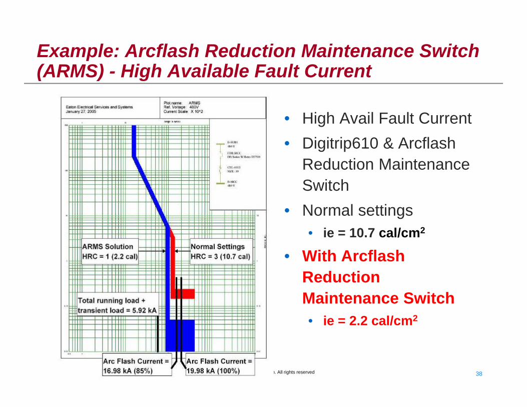
Example: Arcflash Reduction Maintenance Switch (ARMS) - High Available Fault Current
• High Avail Fault Current• Digitrip610 & Arcflash
Reduction Maintenance Switch
• Normal settings• ie = 10.7 cal/cm2
• With Arcflash Reduction Maintenance Switch• ie = 2.2 cal/cm2

39 39© 2009 Eaton Corporation. All rights reserved.
Arc Flash Solutions; REMOTE ARMS– New in 2006

40 40© 2009 Eaton Corporation. All rights reserved.
Multiple Settings Groups
Similar to LV maintenance switch, only for MV applicationsUsed to reduce the trip delay of medium-voltage relays while maintenance is being performed on equipment.Requires relay with multiple settings groups capability, such as the Eaton E-Series Relays

41 41© 2009 Eaton Corporation. All rights reserved.
Substations Without Main SecondariesAFL Retrofit

42 42© 2009 Eaton Corporation. All rights reserved.
CM52 Network Protector with ARMS
• SCADA Communication & Control• Advanced Trip & Close Characteristics• Pendant or Remote Setpoints• Auxiliary Inputs, Trip Event Log, Waveforms
• Rack out CM52 to Test position, Door Closed• Control via Pendant or Communication• Rack in CM52 from Test to stabs, Door Closed
• Dead Front, Draw Out, Lighter Weight Breaker• Fault Close and Latch Rated Breaker• Highest NWP Withstand and Thermal Ratings• Accommodates Internal or External Mount Fuses• Self-Diagnostics, Reduced Maintenance, only 7 replacement parts• Test Position with Test Block simplifies full NWP Testing
• Independent of the MPCV Network Relay• Derives power via CTs from fault current• Sub-cycle non-directional RMS detection• Unlike any conventional Network Protector which provides NO “forward” protection for Collector Bus Network Faults
CM52 Network Protector:
CM52 with ARMS Protection:
CM52 with Remote Racking:Arcflash Reduction Maintenance Systemfor Network Protectors for Spot Networks

© 2010 Eaton Corporation. All rights reserved.
Move People Further Away
44 44© 2009 Eaton Corporation. All rights reserved.
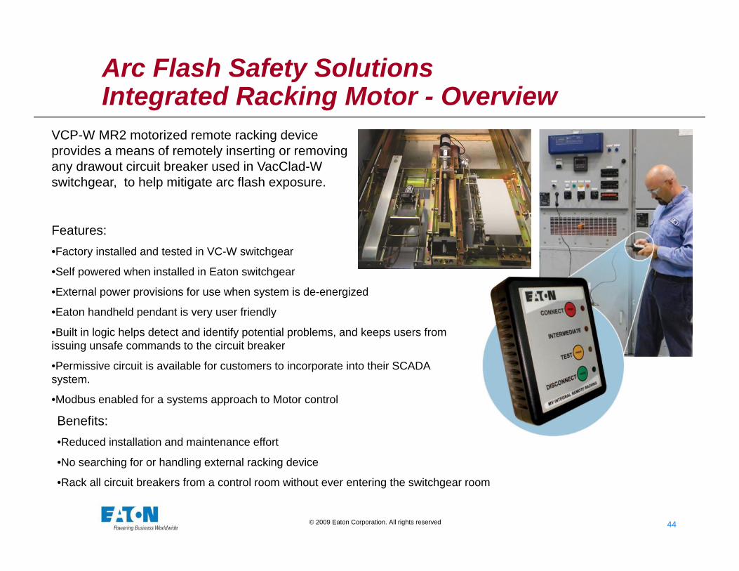
Arc Flash Safety SolutionsIntegrated Racking Motor - Overview
Features:•Factory installed and tested in VC-W switchgear
•Self powered when installed in Eaton switchgear
•External power provisions for use when system is de-energized
•Eaton handheld pendant is very user friendly
•Built in logic helps detect and identify potential problems, and keeps users from issuing unsafe commands to the circuit breaker
•Permissive circuit is available for customers to incorporate into their SCADA system.
•Modbus enabled for a systems approach to Motor control
VCP-W MR2 motorized remote racking device provides a means of remotely inserting or removing any drawout circuit breaker used in VacClad-W switchgear, to help mitigate arc flash exposure.
Benefits:•Reduced installation and maintenance effort
•No searching for or handling external racking device
•Rack all circuit breakers from a control room without ever entering the switchgear room
45 45© 2009 Eaton Corporation. All rights reserved.
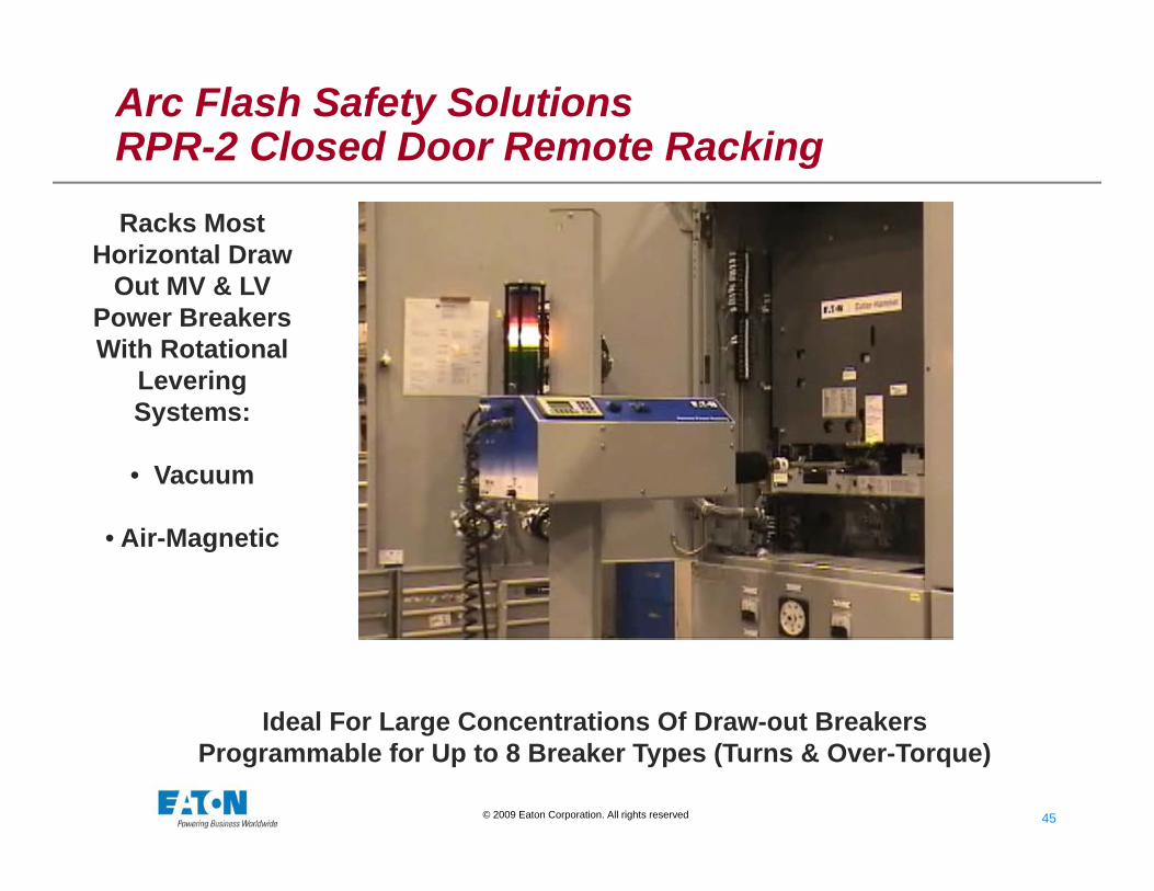
Arc Flash Safety SolutionsRPR-2 Closed Door Remote Racking
Racks Most Horizontal Draw
Out MV & LV Power Breakers With Rotational
Levering Systems:
• Vacuum
• Air-Magnetic
Ideal For Large Concentrations Of Draw-out BreakersProgrammable for Up to 8 Breaker Types (Turns & Over-Torque)

46 46© 2009 Eaton Corporation. All rights reserved.
Arc Flash Safety SolutionsAmpgard ISO Switch Remote Operator
ISO Switch Remote Operator • Mounting Provisions on Each Door• Easy Mounting and Attachment• 25 Foot Pendant• Easy Detachment and Removal
Ampgard MV Vacuum Starter
47 47© 2009 Eaton Corporation. All rights reserved.
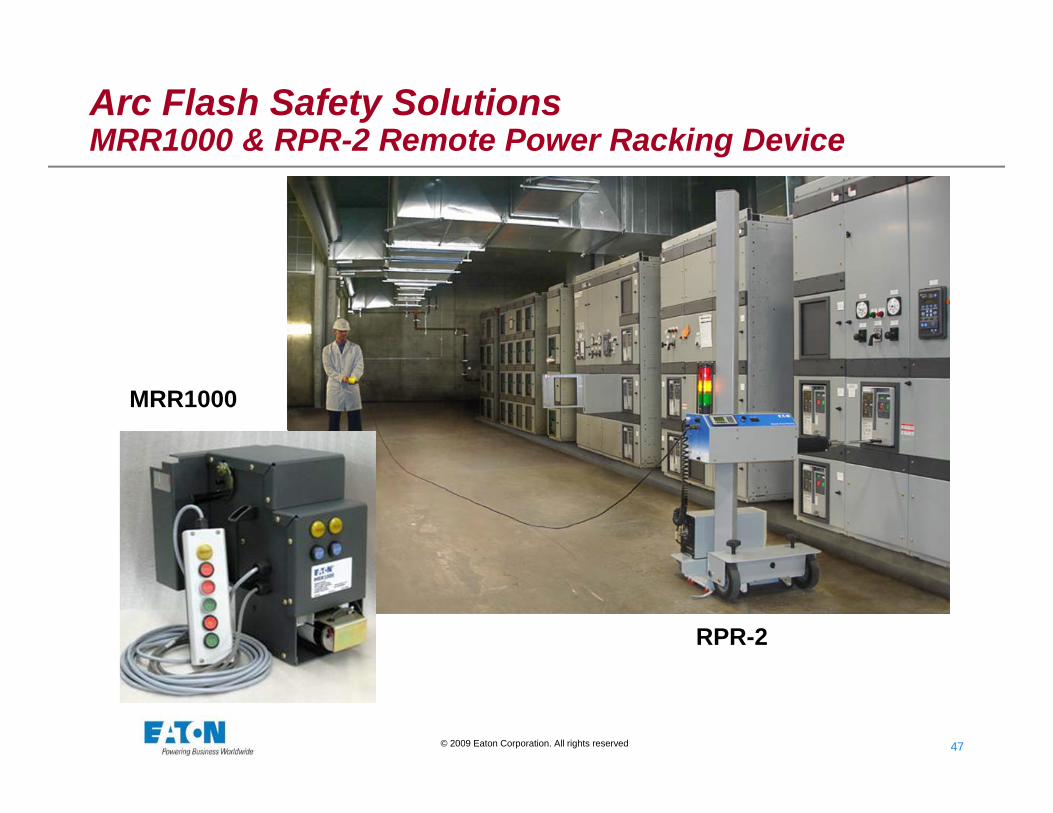
Arc Flash Safety SolutionsMRR1000 & RPR-2 Remote Power Racking Device
ATS Slide.ppt (454 KB)
MRR1000
RPR-2

48 48© 2009 Eaton Corporation. All rights reserved.
Arc Flash Safety SolutionsRotoTractTM - Closed Door Remote Racking (Size 1 – 5)
Simple RotoTractTM Device RPR-2 Programmable Device
Move People Further Away

© 2010 Eaton Corporation. All rights reserved.
Redirect Fault Energy

50 50© 2009 Eaton Corporation. All rights reserved.
5/15 kV Arc Construction
Arc Resistant MV SwitchgearIt always has an Arc Plenum as shown below
Arc Resistant MV Motor Control –AMPGARDIt always has an Arc Plenum as shown above
Arc Resistant LV SwitchgearAvailable w/o as shown above or w/ an Arc Plenum as shown below

© 2010 Eaton Corporation. All rights reserved.
Prevent Fault

52 52© 2009 Eaton Corporation. All rights reserved.
High Resistance Grounding
• HRG Units• Typically Under 5
Amps• Pulsing Contactor• Many Options• LV or MV• Does Not Preclude
PPE• Lowers Probability of
Accident

53 53© 2009 Eaton Corporation. All rights reserved.
FlashGardTM MCCThe Ultimate Solution
54 54© 2009 Eaton Corporation. All rights reserved.
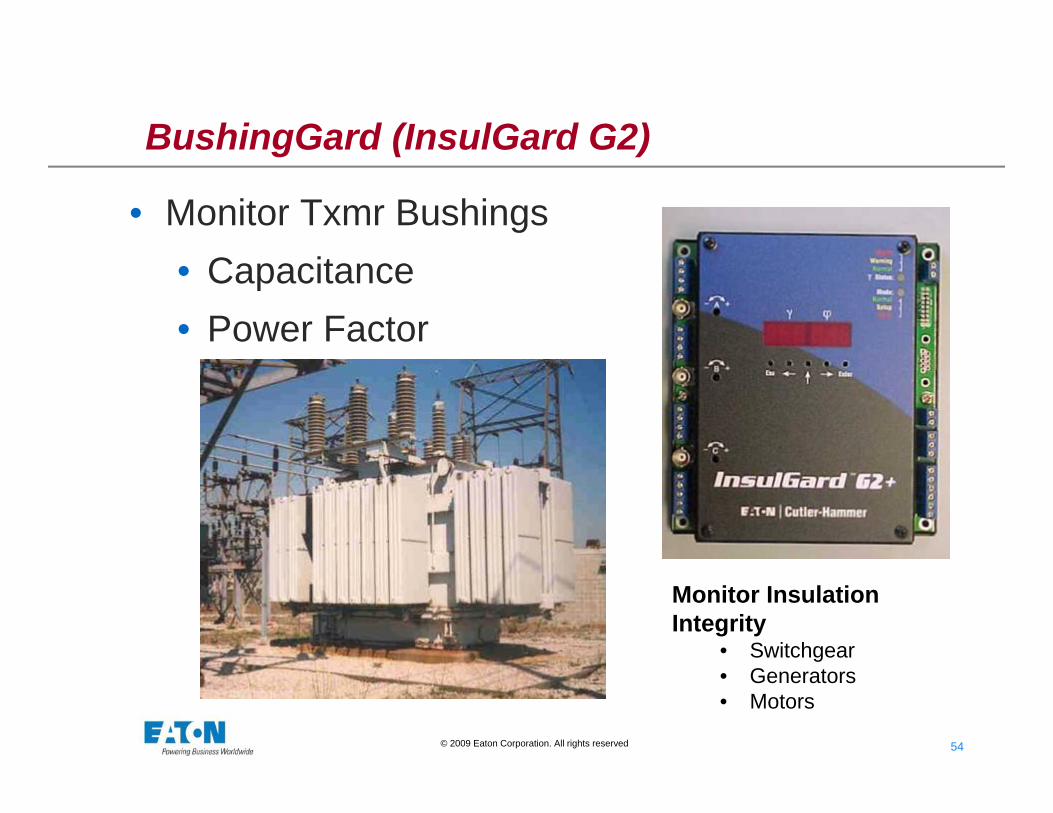
BushingGard (InsulGard G2)
• Monitor Txmr Bushings• Capacitance• Power Factor
Monitor Insulation Integrity
• Switchgear• Generators• Motors
55 55© 2009 Eaton Corporation. All rights reserved.
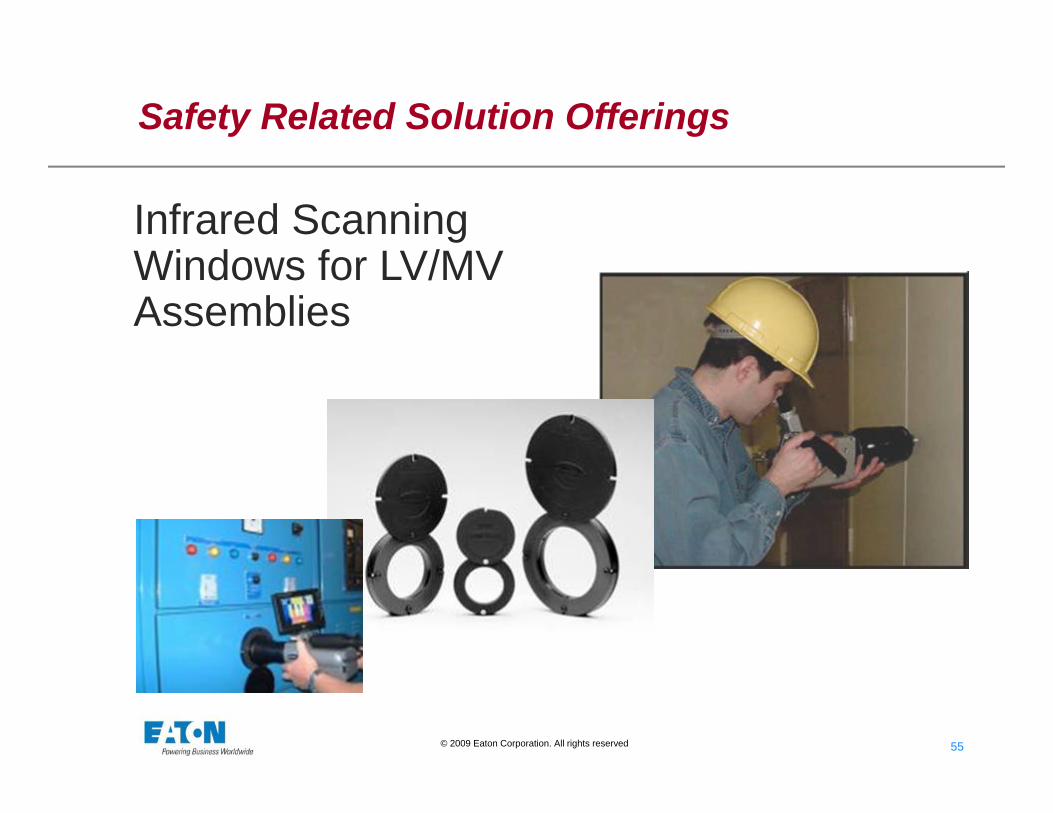
Safety Related Solution Offerings
Infrared Scanning Windows for LV/MV Assemblies

56 56© 2009 Eaton Corporation. All rights reserved.
Continuous Thermal Monitoring
• Monitoring Connecting Joints on a PDU, Utilizing Plastic Bracket System
• Monitoring Individual Connections

57 57© 2009 Eaton Corporation. All rights reserved.
Eaton Resources for AF Safety Solutions
• Eaton Application Engineers & Sales Engineers• EESS District Operations Centers (DOC)• PSE Group - Warrendale and Local PSE• Eaton Websites: http://es.eaton.com/arcflashsafetydemo/
http://www.eaton.com/Electrical/USA/MarketSolutions/Utilities/index.htm
58 58© 2009 Eaton Corporation. All rights reserved.
QUESTIONS ?