Arc Flash Calculations for Consulting Engineersstorage.googleapis.com/rnm-eng-com/uploads/Arc...
49
Arc Flash Calculations for Consulting Engineers By George Puffett, Cammisa and Wipf Rick Miller, RNM Engineering IEEE-SF-IAS November 16, 2004
Transcript of Arc Flash Calculations for Consulting Engineersstorage.googleapis.com/rnm-eng-com/uploads/Arc...

Arc Flash Calculations for Consulting Engineers
By George Puffett, Cammisa and WipfRick Miller, RNM Engineering
IEEE-SF-IASNovember 16, 2004
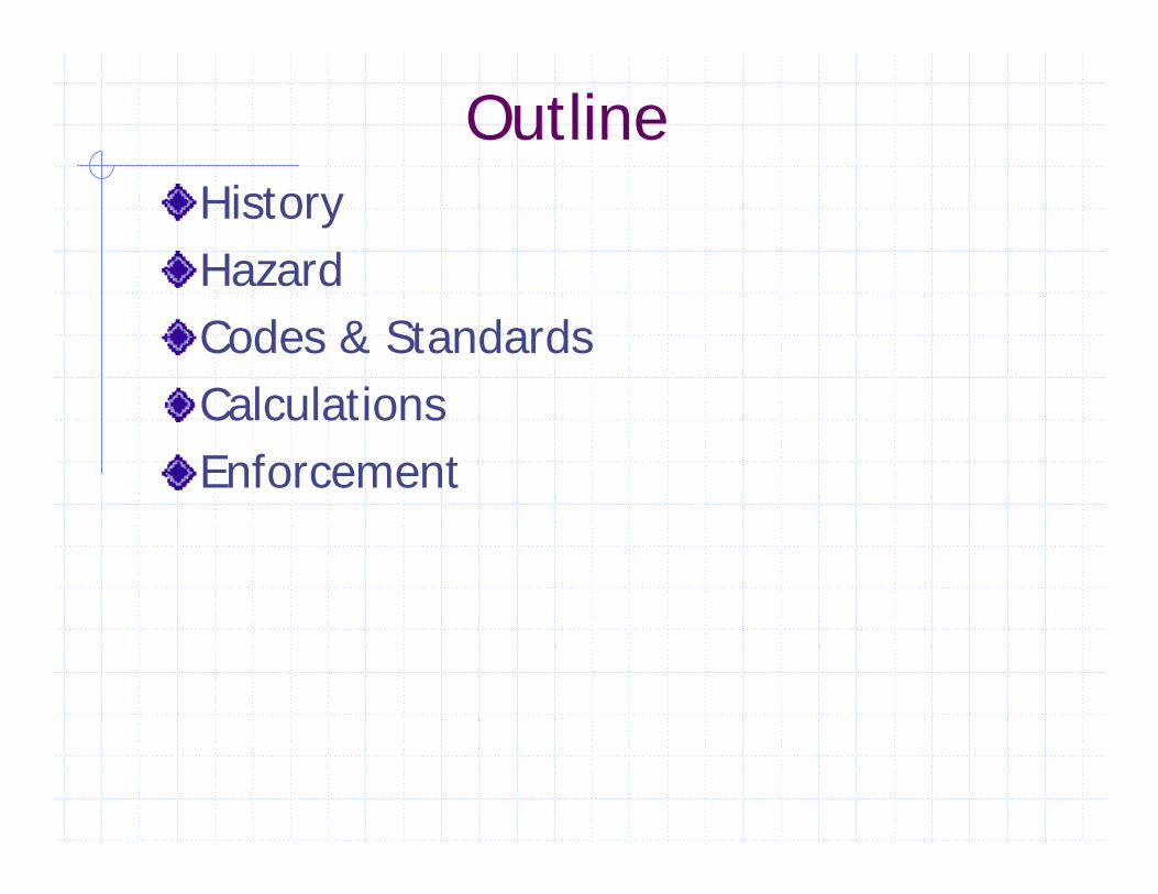
OutlineHistoryHazardCodes & StandardsCalculationsEnforcement

HistoryShock / Electrocution Major HazardRalph Lee 1982
“The Other Electrical Hazard: Electric Arc Blast Burns”Electrical Arc Burns Are a Common InjuryElectrical Arcing is Term Applied to Current Passing Thru a Vapor of Conductive MaterialEstablished Relationship Between Temperature and Skin Burns & Human Tissue Cell Death
IEEE 1584 Expanded Lee’s Work

Recent Local IncidentStanford UniversityTechnician injured at linear accelerator-Ulysses TorassaThursday, October 12, 2004
A technician suffered second and third degree burns Monday after a 480 volt electrical arc erupted during the installation of a circuit breaker at the Stanford Linear Accelerator Center, authorities said.
The man, who was not identified, was installing the device at 11:18 a.m. next to an electrical panel in a section of the 2 mile long accelerator located just west of Interstate 280, said center spokesman Neil Calder.
The arc ignited his clothes and threw him backward, but two co-workers who were nearby were able to put out the flames quickly. He was being treated in the burn unit at Santa Clara Valley Medical Center in San Jose.
Calder said officials had suspended operations at the accelerator for a few days while the accident is investigated but that the halt was unlikely to affect any research work.
SFGate.com

Hazards of Electrical WorkElectrical Shock – Direct ContactElectrical Shock – Vaporized Metal in Arc PlasmaArc Flash Burns (Heat, Fire)Arc Blast (Pressure, Shrapnel, Sound)
Secondary hazards includeFallsFire

Photos of Arc Flash Hazard
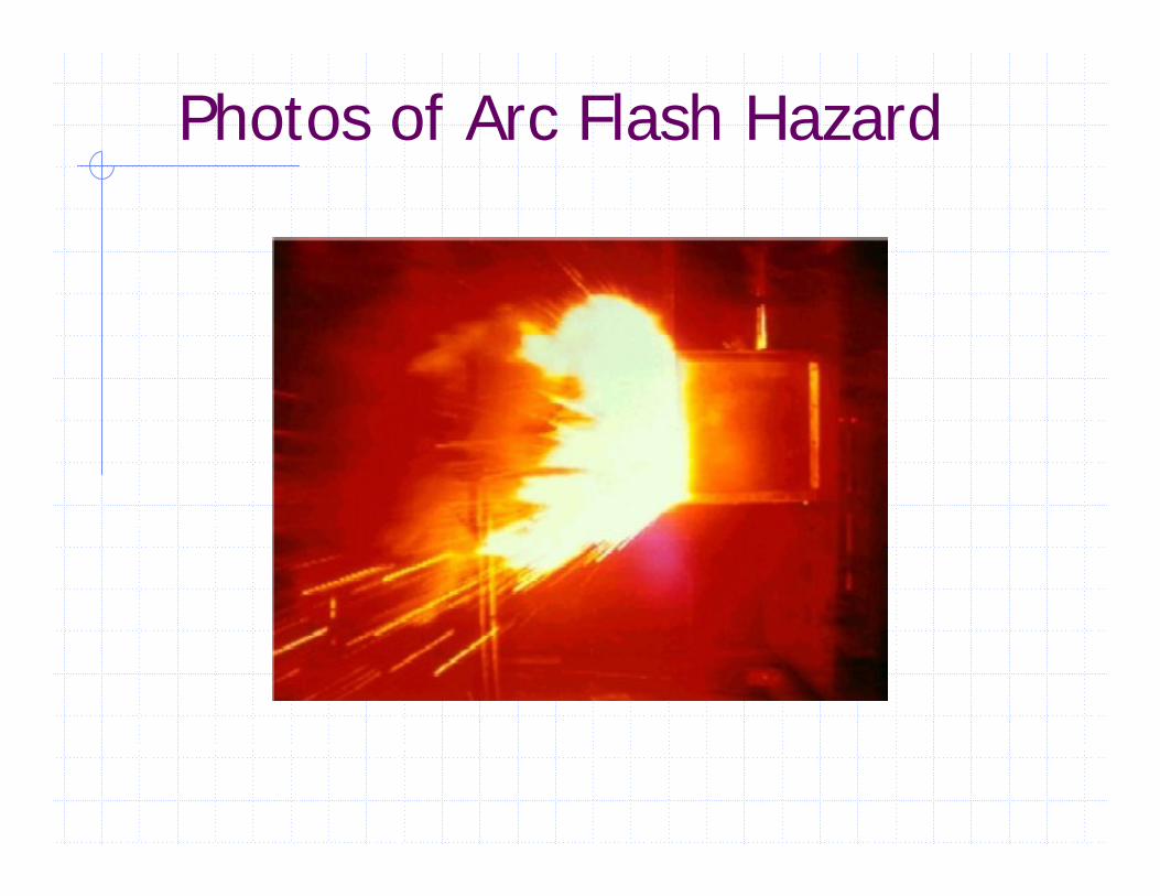
Photos of Arc Flash Hazard

7:30am Nov. 8, 2004 in SF
Vaporizedcopper

Arc Flash Hazard ComparisonSteam (water to vapor) (Heat of Vaporization) at 212° F.Vaporized copper at 5000° F.

Arc Flash Hazard Comparison
Incurable 3rd degree burns
0.1 Sec.200° F
Curable burn0.1 Sec. 176° F
Total cell destruction1 Sec.158° F
Cell breakdown begins
6 Hours110° F
Damage Caused
Duration of Exposure
Skin Temperature

Flash Hazard Analysis A Flash Hazard Analysis must be performed before a person approaches any exposed electrical conductor or circuit part that has not been placed in an electrically safe work condition.The Flash Protection Boundary will establish the need for PPE to cross that boundary.Flame Resistant (FR) clothing and PPE are used by the employee based upon the incident energy associated with the task.
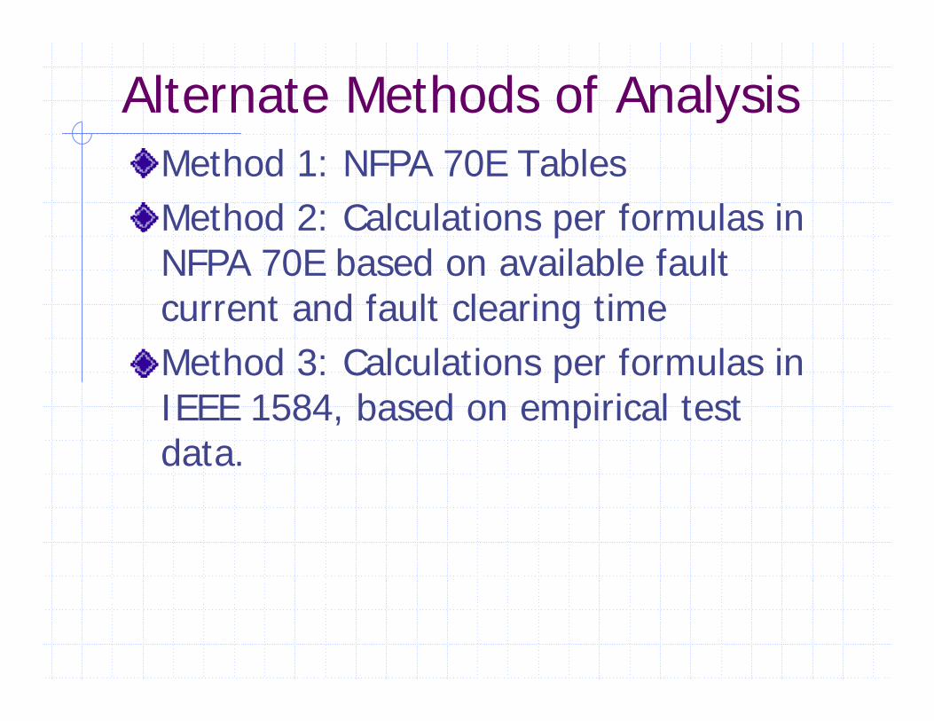
Alternate Methods of AnalysisMethod 1: NFPA 70E TablesMethod 2: Calculations per formulas in NFPA 70E based on available fault current and fault clearing timeMethod 3: Calculations per formulas in IEEE 1584, based on empirical test data.

Definitions of Key TermsIncident EnergyFlash Protection or Arc Flash BoundaryLimited Approach BoundaryRestricted Approach BoundaryProhibited Approach BoundaryQualified PersonWorking Distance
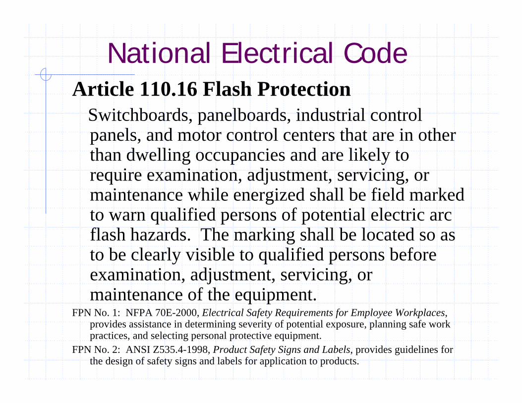
National Electrical CodeArticle 110.16 Flash Protection
Switchboards, panelboards, industrial control panels, and motor control centers that are in other than dwelling occupancies and are likely to require examination, adjustment, servicing, or maintenance while energized shall be field marked to warn qualified persons of potential electric arc flash hazards. The marking shall be located so as to be clearly visible to qualified persons before examination, adjustment, servicing, or maintenance of the equipment.
FPN No. 1: NFPA 70E-2000, Electrical Safety Requirements for Employee Workplaces, provides assistance in determining severity of potential exposure, planning safe work practices, and selecting personal protective equipment.
FPN No. 2: ANSI Z535.4-1998, Product Safety Signs and Labels, provides guidelines for the design of safety signs and labels for application to products.

Sample Label

IEEE & NFPA
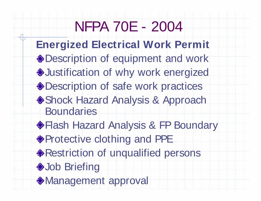
NFPA 70E - 2004 Energized Electrical Work Permit
Description of equipment and workJustification of why work energizedDescription of safe work practicesShock Hazard Analysis & Approach BoundariesFlash Hazard Analysis & FP BoundaryProtective clothing and PPERestriction of unqualified personsJob BriefingManagement approval

Sample Energized Work Permit

DefinitionFlash Hazard Analysis: A study investigating a worker’s potential exposure to arc-flash energy, conducted for the purpose of injury prevention and the determination of safe work practices and the appropriate levels of PPE. [from NFPA 70E 2004]

Hazard Category ClassificationTable 3-3.9.1 Hazard Risk Category
Hazard Risk Category (0 to 4)Voltage Rated Gloves (Yes or No)Voltage Rated Tools (Yes or No)
Table 3-3.9.2 Protective Clothing & PPEProtective Clothing and EquipmentHazard Risk CategoryProtective Systems for Category (-1 to 4)
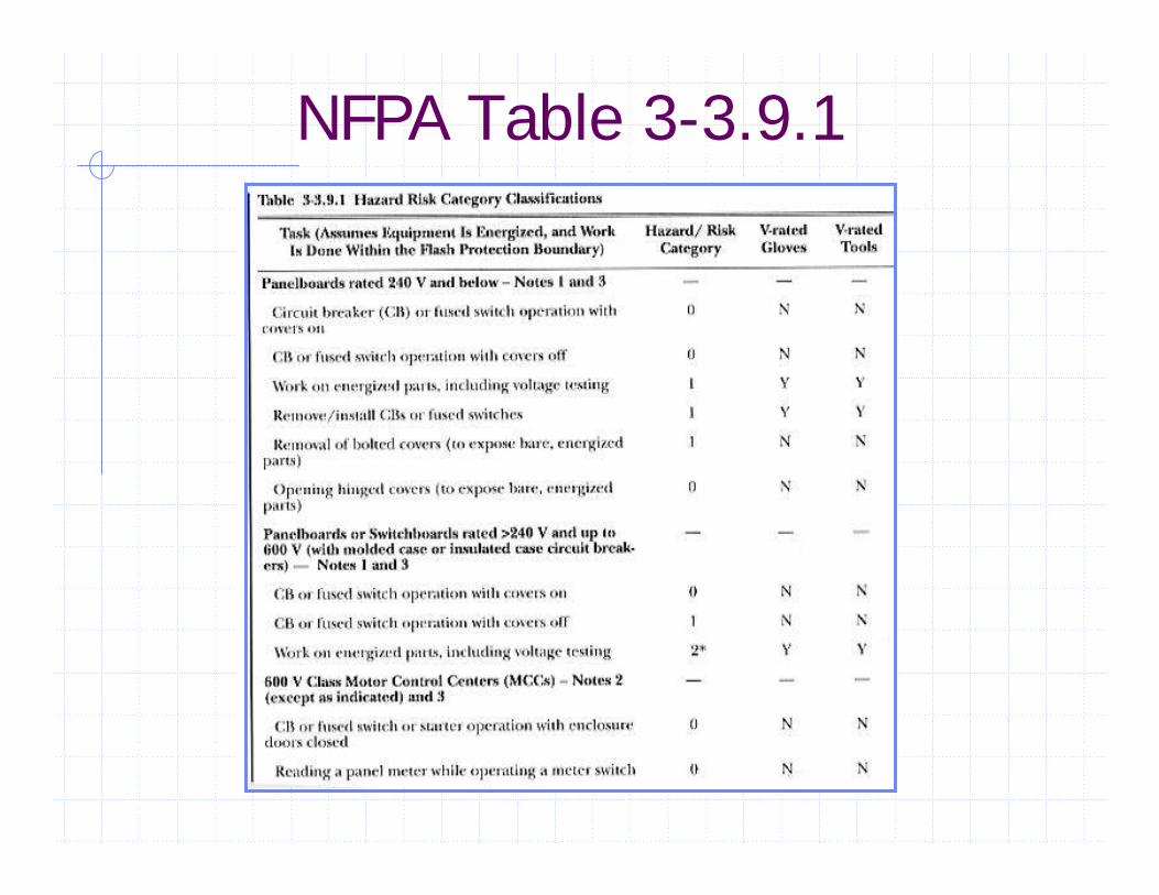
NFPA Table 3-3.9.1

NFPA Table 3-3.9.2

Protective Clothing & PPEUntreated Natural Fiber (not synthetic)
T-shirt, Long-sleeve shirt, Pants
FR Clothing [by employee per NECA]
Long-sleeve shirt, Pants, Coverall, Jacket
FR Protective Equipment [by employer per NECA]
Flash suit jacket, Flash suit pants, Hard hat, FR hard hat liner, Safety glasses, Safety goggles, Face protection, Hearing protection, Leather gloves, Leather boots

Flash Suit

Safety PolicyIt is the policy of the Company to provide safe and healthful working
conditions by acknowledging safety as the highest of priorities in all of our work activities. Knowledge of the job, the hazards involved, and the precautions to be taken are all critical factors in preventing accidents. It is our continual goal to eliminate occupational injuries and illness among our employees.
It is the goal of the Company to have employees properly trained to meet the standards of a “Qualified Person” as set forth by OSHA (US) and OHSA (Canada) and to provide continual improvement of our employee’s job skills and safety awareness through training and communication of vital safety information.
Employees should never feel pressured to work in unsafe conditions or take unnecessary risks by working on equipment, which introducesadditional or increased hazards.
While the Company is committed to providing safe and healthful working conditions for each of its employees, in return the Company expects and insists that each employee recognize their obligation to conduct themselves in strict accordance with our safety policy and with due regard not only for their own safety but for the safety of their fellow employees, sub-contractors and customers as well.

Prerequisite to AnalysisOne-Line DiagramShort Circuit StudyCoordination Study

Concept of CalculationVoltage, Current, Time“Flash Protection Boundary Calculation”:
DC = (2.65 x MVABF x t)1/2
DC = distance in feet for 80° FMVABF = bolted fault at point involvedt = time of arc exposure in seconds
[from NFPA 70E, Part II, Appendix B]

Concept of CalculationVoltage, Current, Time“Flash Protection Boundary Calculation”:
DC = (53 x MVATR x t)1/2
DC = distance in feet for 80° FMVATR = rating of transformer
(For <0.75MVA multiply by 1.25)t = time of arc exposure in seconds
[from NFPA 70E, Part II, Appendix B]

IEEE 1584 CalculationsEmpirically derived formulas based on years of testing at four recognized testing laboratoriesArcing current is calculatedIncident energy is calculated using arcing current and arcing timeEquations tailored for specific protective devices – fuses or circuit breakers and ampere rating

IEEE 1584 Formulas

IEEE 1584 Formulas

IEEE 1584 Formulas

IEEE 1584 Formulas
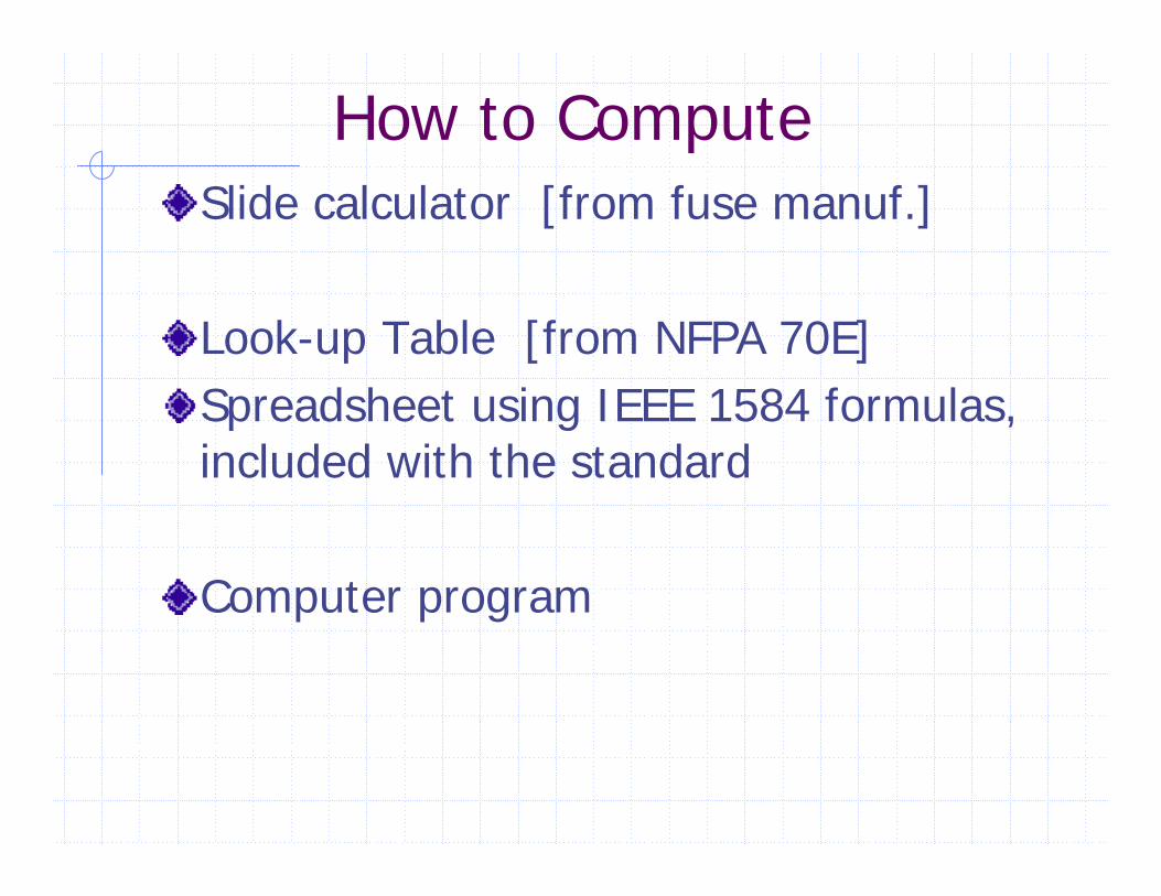
How to ComputeSlide calculator [from fuse manuf.]
Look-up Table [from NFPA 70E]Spreadsheet using IEEE 1584 formulas, included with the standard
Computer program

Slide Calculator

Example Computer Programs

Sample One-Line Diagram-BF

Sample One-Line Diagram-AF

Sample One-Line Diagram-AFB

Sample One-Line Diagram-IE

Sample Short Circuit Study

Sample Coordination Study

Sample Arc Flash Results-1

Sample Arc Flash Results-2

Sample Arc Flash Results-3

Sample Arc Flash Results-4

EnforcementENGINEERS
NEC 2002, Art. 110.16California Electrical Code 2004 based on NEC 2002
Published early 2005Effective 180 days later 2005
EMPLOYERSOSHA 1990 recognizes NFPA 70E as a national consensus standard

Obligations and OpportunitiesENGINEERS
Perform Arc Flash Analysis
EMPLOYERSComply with OSHA and NFPA 70E

The End