ARC: Analysis of Raft Consensus - University of Cambridge · ARC: Analysis of Raft Consensus Heidi...
69
Technical Report Number 857 Computer Laboratory UCAM-CL-TR-857 ISSN 1476-2986 ARC: Analysis of Raft Consensus Heidi Howard July 2014 15 JJ Thomson Avenue Cambridge CB3 0FD United Kingdom phone +44 1223 763500 http://www.cl.cam.ac.uk/
Transcript of ARC: Analysis of Raft Consensus - University of Cambridge · ARC: Analysis of Raft Consensus Heidi...

Technical ReportNumber 857
Computer Laboratory
UCAM-CL-TR-857ISSN 1476-2986
ARC: Analysis of Raft Consensus
Heidi Howard
July 2014
15 JJ Thomson AvenueCambridge CB3 0FDUnited Kingdomphone +44 1223 763500
http://www.cl.cam.ac.uk/

c© 2014 Heidi Howard
This technical report is based on a dissertation submittedMay 2014 by the author for the degree of Bachelor of Arts(Computer Science Tripos) to the University of Cambridge,Pembroke College.
Technical reports published by the University of CambridgeComputer Laboratory are freely available via the Internet:
http://www.cl.cam.ac.uk/techreports/
ISSN 1476-2986

Abstract
The Paxos algorithm, despite being synonymous with distributed consensus for adecade, is famously difficult to reason about and implement due to its non-intuitiveapproach and underspecification. In response, this project implemented and evalu-ated a framework for constructing fault-tolerant applications, utilising the recentlyproposed Raft algorithm for distributed consensus. Constructing a simulation frame-work for our implementation enabled us to evaluate the protocol on everything fromunderstandability and efficiency to correctness and performance in diverse networkenvironments. We propose a range of optimisations to the protocol and released to thecommunity a testbed for developing further optimisations and investigating optimalprotocol parameters for real-world deployments.
3

Acknowledgements
I have thoroughly enjoyed working on this project and my final year at Cambridge, itwouldn’t have been possible without the help and support of the following wonderfulpeople: Anil Madhavapeddy, not only have you been an excellent supervisor but youhave been my mentor over the last two years and Diego Ongaro, author of Raft, whohas taken his time to support me in reproducing his results and sharing his ideas. Iwould also like to thank Malte Schwarzkopf and Chris Hadley for providing excellentfeedback on my dissertation, which forms the basis of this technical report.
4

Contents
1 Introduction 91.1 Motivation . . . . . . . . . . . . . . . . . . . . . . . . . . . . . . . . . . . . 91.2 Related Work . . . . . . . . . . . . . . . . . . . . . . . . . . . . . . . . . . 10
1.2.1 Definition of Consensus . . . . . . . . . . . . . . . . . . . . . . . . 101.2.2 CAP theorem: Conjecture, Correctness & Controversy . . . . . . 111.2.3 FLP Impossibility Result . . . . . . . . . . . . . . . . . . . . . . . . 121.2.4 Two and Three Phase Commit . . . . . . . . . . . . . . . . . . . . 121.2.5 (Multi-)Paxos . . . . . . . . . . . . . . . . . . . . . . . . . . . . . . 121.2.6 Viewstamped Replication . . . . . . . . . . . . . . . . . . . . . . . 14
2 Preparation 152.1 Assumptions . . . . . . . . . . . . . . . . . . . . . . . . . . . . . . . . . . . 152.2 Approach . . . . . . . . . . . . . . . . . . . . . . . . . . . . . . . . . . . . . 162.3 Raft Protocol . . . . . . . . . . . . . . . . . . . . . . . . . . . . . . . . . . . 17
2.3.1 Leader Election . . . . . . . . . . . . . . . . . . . . . . . . . . . . . 172.3.2 Log Replication . . . . . . . . . . . . . . . . . . . . . . . . . . . . . 182.3.3 Safety and Extra Conditions . . . . . . . . . . . . . . . . . . . . . 23
2.4 Requirements Analysis . . . . . . . . . . . . . . . . . . . . . . . . . . . . . 262.5 Choice of Tools . . . . . . . . . . . . . . . . . . . . . . . . . . . . . . . . . 27
2.5.1 Programming Languages . . . . . . . . . . . . . . . . . . . . . . . 272.5.2 Build Systems . . . . . . . . . . . . . . . . . . . . . . . . . . . . . . 272.5.3 Libraries . . . . . . . . . . . . . . . . . . . . . . . . . . . . . . . . . 272.5.4 Testing . . . . . . . . . . . . . . . . . . . . . . . . . . . . . . . . . . 27
2.6 Summary . . . . . . . . . . . . . . . . . . . . . . . . . . . . . . . . . . . . . 28
3 Implementation 293.1 Simulation Framework . . . . . . . . . . . . . . . . . . . . . . . . . . . . . 293.2 Clock . . . . . . . . . . . . . . . . . . . . . . . . . . . . . . . . . . . . . . . 303.3 State . . . . . . . . . . . . . . . . . . . . . . . . . . . . . . . . . . . . . . . . 32
3.3.1 Node State . . . . . . . . . . . . . . . . . . . . . . . . . . . . . . . . 343.3.2 Client State . . . . . . . . . . . . . . . . . . . . . . . . . . . . . . . 35
5
3.4 Events . . . . . . . . . . . . . . . . . . . . . . . . . . . . . . . . . . . . . . . 353.5 Event List . . . . . . . . . . . . . . . . . . . . . . . . . . . . . . . . . . . . 363.6 Simulation Parameters . . . . . . . . . . . . . . . . . . . . . . . . . . . . . 373.7 Non-determinism . . . . . . . . . . . . . . . . . . . . . . . . . . . . . . . . 373.8 Correctness . . . . . . . . . . . . . . . . . . . . . . . . . . . . . . . . . . . . 383.9 Summary . . . . . . . . . . . . . . . . . . . . . . . . . . . . . . . . . . . . . 38
4 Evaluation 414.1 Calibration . . . . . . . . . . . . . . . . . . . . . . . . . . . . . . . . . . . . 414.2 Leader Election . . . . . . . . . . . . . . . . . . . . . . . . . . . . . . . . . 444.3 Log Replication and Client Semantics . . . . . . . . . . . . . . . . . . . . 494.4 Testing . . . . . . . . . . . . . . . . . . . . . . . . . . . . . . . . . . . . . . 524.5 Summary . . . . . . . . . . . . . . . . . . . . . . . . . . . . . . . . . . . . . 54
5 Conclusion 555.1 Recommendations . . . . . . . . . . . . . . . . . . . . . . . . . . . . . . . 555.2 Future Work . . . . . . . . . . . . . . . . . . . . . . . . . . . . . . . . . . . 57
Bibliography 59
A Raft Specification for Simulation 63A.1 State . . . . . . . . . . . . . . . . . . . . . . . . . . . . . . . . . . . . . . . . 63A.2 RPCs . . . . . . . . . . . . . . . . . . . . . . . . . . . . . . . . . . . . . . . 65
A.2.1 Append Entries . . . . . . . . . . . . . . . . . . . . . . . . . . . . . 65A.2.2 Client Commit . . . . . . . . . . . . . . . . . . . . . . . . . . . . . 66A.2.3 Request Vote . . . . . . . . . . . . . . . . . . . . . . . . . . . . . . 67
B Simulation Parameters 68
6

List of Figures
1.1 Timeline of the key developments in distributed consensus. . . . . . . . 111.2 Timing diagram of successful Paxos between five nodes . . . . . . . . . 131.3 Timing diagram of duelling proposers in Paxos . . . . . . . . . . . . . . 13
2.1 Components of the replicated state machine approach. . . . . . . . . . . . . 162.2 State transition model for Raft consensus . . . . . . . . . . . . . . . . . . 172.3 Timing diagram of successful election . . . . . . . . . . . . . . . . . . . . 192.4 Timing diagram of election timeout and restart . . . . . . . . . . . . . . . 202.5 Timing diagram of leader stepping down . . . . . . . . . . . . . . . . . . 212.6 General example of replicated logs . . . . . . . . . . . . . . . . . . . . . . 222.7 Example of simple command commit between three nodes . . . . . . . . 232.8 Example of leader using AppendEntries RPCs to bring a range of logs
up to a consistent state . . . . . . . . . . . . . . . . . . . . . . . . . . . . . 242.9 Example of why the extra commit conditions are necessary . . . . . . . 252.10 Raft’s guarantees to provide distributed consensus . . . . . . . . . . . . 25
3.1 Example DES of Raft consensus . . . . . . . . . . . . . . . . . . . . . . . . 313.2 Shared module signature of FakeTime and RealTime. . . . . . . . . . . . . 323.3 Demonstration of enforcing time monotonicity. . . . . . . . . . . . . . . . 323.4 Example timeline of terms . . . . . . . . . . . . . . . . . . . . . . . . . . . 323.5 Use of type system to enforce monotonicity of Term. . . . . . . . . . . . . 333.6 Functor to limit protocol interaction with state to statecalls. . . . . . . . . 333.7 Example node running a key value store using Raft consensus. . . . . . 343.8 Mutually recursive type definitions of t and event. . . . . . . . . . . . . . 353.9 Monad signature and Option monad implementation. . . . . . . . . . . . 363.10 Signature for data structures implementing Event List. . . . . . . . . . . 363.11 SplayTree as a functor over Item . . . . . . . . . . . . . . . . . . . . . . . . 373.12 Type sharing constraint between item and Event.t . . . . . . . . . . . . . 373.13 Example OCaml interface to each node’s run-time monitor, generated
from SPL. . . . . . . . . . . . . . . . . . . . . . . . . . . . . . . . . . . . . . 393.14 Raft’s mode of operation transitions modelling in SPL. . . . . . . . . . . 40
7

4.1 Time taken to establish leadership as a function of follower timeout . . 424.2 Cumulative distribution of the time until first election . . . . . . . . . . 434.3 Time taken to establish leadership as a function of follower timeout . . 454.4 Investigating the impact of alternative candidate timeouts . . . . . . . . 474.5 Box plot showing effect of optimisations on network traffic . . . . . . . 484.6 Four examples of diverse network topologies . . . . . . . . . . . . . . . . 504.7 Example of livelock and proposed solution . . . . . . . . . . . . . . . . . 534.8 Screenshot of Travis CI web GUI for testing git commit history. . . . . . 54
B.1 Table detailing the available simulation parameters . . . . . . . . . . . . 69
8
Chapter 1
Introduction
This technical report describes the implementation, analysis and refinement of theRaft consensus algorithm, for building fault-tolerant applications on a cluster of repli-cated state machines.
1.1 Motivation
Distributed consensus builds reliable systems from unreliable components, it formsthe foundation of many distributed systems and is a fundamental problem in com-puter science. Its applications range from fault-tolerant databases, lock managers,group membership systems and leader election to terminating reliable broadcast andclock synchronization, not forgetting Greek parliamentary proceedings [14] and gen-erals invading a city [19]. The subject of this report is the implementation of fault-tolerant applications by replicated deterministic state machines and co-ordinatingtransitions, known as the replicated state machine approach.
Leslie Lamport’s Paxos protocol [14] is at the heart of distributed consensus inboth research and industry. Despite being synonymous with consensus for a decade,it is famously difficult to understand, reason about and implement because of its non-intuitive approach and the lack of universal agreement on the algorithm for multi-Paxos.
Lamport’s original description of Paxos [14], though highly cited, is notoriouslydifficult to understand and therefore has led to much follow up work, explaining theprotocol in simpler terms [15, 36] and optimising it for practical systems [18, 17, 25].Lamport went on to sketch some approaches to Multi-Paxos, based on consecutiveruns of Paxos, but its under-specification led to divergent interpretations and imple-mentations.
The search for a more understandable consensus algorithm is not simply abouteasing the right of passage for computer science undergraduates or aiding software
9

10 CHAPTER 1. INTRODUCTION
developers but also about bridging the divide between the formal verification andsystem communities.
Raft [28, 27] by Diego Ongaro and John Ousterhout promises distributed consen-sus, which provides the same guarantees as Multi-Paxos under the same assumptions,with enhanced understandability from an intuition-focused approach and proof ofsafety.
On first sight, Raft is the silver bullet to a decade old problem in distributed sys-tems. Since the draft was first released online, it has been popular with developers,leading to a dozen implementations. However at the time of writing, the Raft paperhas yet to be published at a peer reviewed venue1 and therefore there does not existany formal follow-up literature.
This project will evaluate the claims made by the paper, from its usability to cor-rectness. Our conclusions will be the first published assessment of the protocol andhopefully will either spark a new direction in distributed consensus or demonstrateits shortcomings.
1.2 Related Work
We have seen that distributed consensus is fundamental to today’s computer systems.Now we consult with the two schools of thought, the theory of distributed consensuswhich demonstrates that true consensus is impossible to achieve and the disciplineof engineering practical solutions, which aims to achieve the impossible by reshapingour assumptions and guarantees. Figure 1.1 highlights the key developments in thisfield.
1.2.1 Definition of Consensus
Consensus requires the following conditions to be met:
1. Agreement: all correct nodes2 arrive at the same value (the safety property);
2. Validity: the value chosen is one that was proposed by a correct node (the non-triviality property);
3. Termination: all correct nodes eventually decide on a value (the liveness property).
Traditional consensus problems require that, in an asynchronous system, agreementand validity must be met regardless of the number of non-Byzantine failures [29]
1The paper has now appeared in 2014 USENIX Annual Technical Conference, June 2014.2A correct node is a node that is currently running, so either it has not fail-stopped or has restarted
after a fail-recover.

1.2. RELATED WORK 11
1985 FLP Impossibility Result [8].
1988 Oki and Liskov’s Viewstamped Repication [26].
1998 Lamport’s original Paxos paper "Part-Time Parliment" [8].
2000 Brewer proposes CAP conjecture during Keynote at PODC [2].
2002 Proof of CAP by Gilbert and Lynch [10].
2005 Lamport’s Technical Report on Generalized Consensus & Paxos [16].
2013 Raft Consensus Paper first available online [28].
Figure 1.1: Timeline of the key developments in distributed consensus.
and all three must be met given the number of non-Byzantine failures is less thana threshold value. The number of nodes which are required to participate in agree-ment is known as the Quorum size. For multi-Paxos (§1.2.5), Viewstamped Replication(§1.2.6) and Raft (§2.2), to tolerate at most f failures, the quorum size is f + 1 for acluster of 2 f + 1 nodes. The quorum intersection property ensures that for any twoquora from the 2 f + 1 nodes there will be an intersection of at least one node. Thus ifwe operate on any quorum, at least one member of any future quorum will be awareof the previous operation.
1.2.2 CAP theorem: Conjecture, Correctness & Controversy
The CAP conjecture [2] was proposed by Eric Brewer in 2000, it argued that it is nec-essary to compromise at least one of Consistency, Availability and Partition Tolerancein a distributed system.
CAP was formally proven two years later [10] operating in asynchronous condi-tions by considering two nodes either side of a network partition. If these two nodesreceive two conflicting client requests then they must both accept the requests, thuscompromising Consistency or at least one of them must not accept the request, thuscompromising Availability.
There has been much confusion over the CAP theorem, as noted by Brewer [1]himself. Brewer argues that the two of three formula is misleading as it oversimpli-fies the complex interactions between the properties. Partitions are often rare andconsistency is not a binary concept, but a whole spectrum of models from Atomicity,Consistency, Isolation and Durability (ACID) to Basically Available Soft-state services with

12 CHAPTER 1. INTRODUCTION
Eventual-consistency (BASE). The consistency in CAP was intended by Brewer to besingle-copy consistency [1].
1.2.3 FLP Impossibility Result
The FLP result [8] proves that it is not possible to guarantee consensus on a singlevalue, if one or more processes is fail-stop faulty, in an asynchronous system with re-liable communication. The asynchronism of the system means that we cannot reliablydifferentiate between a slow process or message and a failed node, even if we assumethat communication is reliable.
1.2.4 Two and Three Phase Commit
In two-phase commit a co-ordinator attempts to commit a value in two distinct phases:the proposal phase where a co-ordinator contacts all other nodes to propose a valueand collect responses, either a commit or abort from each node and the commit phasewhere the co-ordinator tells all other nodes whether to commit or abort the previouslyproposed value. If a co-ordinator fails during the commit phases, then another nodecould try to recover by asking nodes how they voted in the proposal phase. However ifan additional node has failed we cannot know who it voted for and we cannot simplyabort the transaction as the co-ordinator may have already told the failed node tocommit and therefore we must block until the node recovers.
Three-phase commit [32] provides liveness by adding a third prepare to commitphase between the proposal and commit stages. This phase has the co-ordinator sendprepare to commit messages to all nodes and proceed to the commit phase as long asall nodes acknowledge receipt, otherwise it aborts the transaction. If the co-ordinatorfails during the commit stage, the nodes will timeout waiting for the commit phase andcommit the transaction themselves, in the knowledge that all nodes must have agreedto commit the transaction for the protocol to reach this stage. If the co-ordinator failsduring the prepare to commit or proposal phases then, safe in the knowledge that nonode will have committed the transaction, the nodes will consider the transactionaborted.
Neither 2PC or 3PC allows for asynchronous systems or network partitions.
1.2.5 (Multi-)Paxos
Paxos considers the agreement over a single value, as shown in in Figure 1.2 andFigure 1.3. A node or set of nodes becomes a Proposer(s), each generating a uniquesequence number which is greater than any they have previously seen, for examplen + 1||nodeID, where n is the first element of the highest sequence number seen so

1.2. RELATED WORK 13
1
2
3
4
5
PROPOSE(11)COMMIT(11,a)
PROPOSE(n)PROMISE(n,v)COMMIT(n,v)ACCEPT(n)
Figure 1.2: Successful Paxos: node 1 is the first proposer and all nodes promise therequest as it is the first one they have seen. Node 1 is then free to commit a value ofits choosing.
1
2
3
4
5
PROPOSE(11)
PROPOSE(15)
COMMIT(11,b)PROPOSE(21)
COMMIT(15,a)
PROPOSE(n)PROMISE(n,v)COMMIT(n,v)ACCEPT(n)REJECT(n)
Figure 1.3: Duelling proposers in Paxos: initially node 1 gets the nodes to promise tosequence number 11. Node 5 then gets the nodes to promise to sequence number 15.When the nodes receive the commit(11,b) from node 1, they all reply with reject(15)since 15 is the last sequence number they have seen. In response, node 1 tries to pro-pose again with sequence number 21 and the nodes promise. When the nodes receivethe commit(15,a) from node 1, they all reply with reject(21) since the last sequencenumber they have seen is 21. This process could continue indefinitely.

14 CHAPTER 1. INTRODUCTION
far. The proposer broadcasts a propose message (including its sequence number) to allother nodes.
On receipt of a propose message, each node compares the sequence number tothe highest number it has already seen. If this is the highest it has seen, the nodereplies with a promise, including the last value accepted and its sequence number, ifany. Otherwise the node responds with a reject message and the highest sequencenumber it has seen. If a strict majority of nodes reply with a promise message then theproposer chooses the value received with the highest sequence number. If no valuesare received, then the proposer is free to choose a value. The proposer then broadcasts acommit message (including sequence number and value) to all nodes.
On receipt of a commit message, each node compares the sequence number to thehighest number it has already seen. If the sequence number is the highest it has seenand if the value is the same as any previously accepted value, then the node replieswith an accept (as demonstrated in Figure 1.2), otherwise the node responds with areject message (as demonstrated in Figure 1.2) and the highest sequence number ithas seen. If a strict majority of nodes reply with an accept message, then the value hasbeen committed and the protocol terminates, otherwise the protocol starts again.
Multi-Paxos [15] is the chaining together of a series of instances of Paxos to achieveconsensus on a series of values such as a replicated log. Multi-Paxos uses leaders,long-term proposers who are therefore able to omit the propose message when theywere the last node to commit a value. This series of values is recorded by each node tobuild fault tolerant applications using the replicated state machine approach (detailed in§2.2) and to enable nodes which have fail-recovered to catch up. This is a notoriouslycomplicated protocol to get to grips with, demonstrating the need for new consensusalgorithms such as Raft.
1.2.6 Viewstamped Replication
Viewstamped Replication (VR) [26, 20] is the most similar of existing protocols to RaftConsensus, though we will not explain the protocol in detail here due to the consider-able overlap with Raft Consensus. It is worth highlighting that VR uses round-robinfor leader election instead of the eager algorithm used in Raft and that VR has allnodes actively communicating, allowing for interesting features such as the ability tooperate without non-volatile storage, though it can be more difficult to reason about.

Chapter 2
Preparation
2.1 Assumptions
Raft consensus operates under the same set of assumptions as Multi-Paxos. The vastliterature on Multi-Paxos details techniques to broaden the application, but here weare only considering classic Multi-Paxos. These assumptions are as follows:
1. Network communication between nodes is unreliable including network delays,partitions, and packet loss, duplication, and re-ordering;
2. Nodes have access to infinite persistent storage that cannot be corrupted andany write to persistent storage will be completed before crashing (known aswrite-ahead logging);
3. Nodes operate in an asynchronous environment with faulty clocks, no upperbound exists for the delay of messages and nodes may operate at arbitraryspeeds;
4. Byzantine failures [29] cannot occur;
5. Nodes are statically configured with a knowledge of all other nodes in the clus-ter, cluster membership cannot change dynamically;
6. The protocol has use of infinitely large monotonically increasing values;
7. Clients of the application must communicate with the cluster via the currentleader, it is the responsibility of the client to determine which one of them is cur-rently leader. The clients are statically configured with knowledge of all nodes;and
8. The state machines running on each node all start in the same state and responddeterministically to client operations.
15

16 CHAPTER 2. PREPARATION
2.2 Approach
Client
ConsensusModule
Client
ConsensusModule
ConsensusModule
Log
State Machine
ConsensusModule
Log
State Machine
ConsensusModule
Log
State Machine
Network
Figure 2.1: Components of the replicated state machine approach.
We will frame the challenge of distributed consensus in the context of a replicatedstate machine (Figure 2.1), drawing a clear distinction between the state machine (afault-tolerant application), the replicated log and the consensus module (handled by theconsensus protocol like Multi-Paxos or Raft).
The clients interact with the replicated state machine via commands. These com-mands are given to the consensus module, which determines if it is possible to com-mit the command to the replicated state machine and, if possible, does so. The statemachine must be deterministic, so that when commands are committed the state ma-chines remain identical. A fault-tolerant database is an example of one such applica-tion. Once a command has been committed, the consensus protocol guarantees thateventually the command will be committed on every live state machine and they willbe committed in order. This provides linearisable semantics from the client, definedas each command from the client appearing to execute instantaneously, exactly once,at some point between its invocation and positive response.
This perspective on distributed consensus has been chosen as it mimics real-worldapplications. Zookeeper [13], the currently most popular open source consensus ap-plication and Chubby [4], a fault-tolerant, distributed locking mechanism used by ap-plications such as the Google Filesystem [9] and Bigtable [6], both use the replicatedstate machine approach [5].

2.3. RAFT PROTOCOL 17
Follower Candidate Leader
starts up/recovers times out,
starts election
times out,new election
receives votes frommajority of servers
discovers currentleader of new term
discovers server with higher term
Figure 2.2: State transition model for Raft consensus.
In the pursuit of understandability and in contrast to the approach of View-stamped Replication, Raft uses strong leadership, which extends the ideas of leader-driven consensus by adding the following conditions:
1. All message passing will be initialised by a leader (or a node attempting to be-come leader). The protocol specification makes this explicit by modelling com-munications as RPCs, emphasizing the clear roles of a node as distinctly eitheractive or passive.
2. Clients must contact the leader directly to communicate with the system.
3. For a system to be available it is necessary (but not sufficient) for a leader tohave been elected. If the system is in the process of electing a leader, even if allnodes are up, the system is unavailable.
2.3 Raft Protocol
2.3.1 Leader Election
Each node has a consensus module, which is always operating within one of thefollowing modes:
• Follower: A passive node, which only responds to RPC’s and will not initiateany communications.
• Candidate: An active node which is attempting to become a Leader, they initiateRequestVote RPC’s.

18 CHAPTER 2. PREPARATION
• Leader: An active node which is currently leading the cluster, this node handlesrequests from clients to interact with the replicated state machine and initiatesAppendEntries RPC’s.
Events cause the nodes to transition between these modes, as shown by the nonde-terministic finite automaton (NFA) in Figure 2.2. These events are all either temporal,such as the protocol’s four main timers Follower Timeout, Candidate Timeout, LeaderTimeout and Client Timeout. Otherwise they can be spatial, such as receiving Appen-dEntries, RequestVote or ClientCommit RPC’s from other nodes.
Since we cannot assume global clock synchronization, global partial ordering onevents is achieved with a monotonically increasing value, known as term. Each nodestores its perspective of the term in persistent storage. A node’s term is only updatedwhen it (re-)starts an election or when it learns from another node that its term is out ofdate. All messages include the source node’s term, which is checked by the receivingnode. If the source’s term is smaller, the response is negative. If the recipient’s termis smaller, then its term is updated before parsing the message, likewise if their termshad been the same.
On startup or recovery from a failure, a node becomes a follower and waits tobe contacted by the leader, which broadcasts regular empty AppendEntries RPC’s. Anode operating as a follower will continue to do so unless it fails to hear from acurrent leader or grant a vote to a candidate (details below) within its Follower Timer.If this occurs a follower will transition to a candidate.
On becoming a candidate, a node will increment its term, vote for itself, start itsCandidate Timer and send a RequestVote RPC to all other nodes. As seen in the NFA(Figure 2.2) for Raft, there are three possible outcomes of this election. Either thecandidate will receive at least a strict majority of votes and become leader for thatterm (Figure 2.3), or it will fail to receive enough votes and restart the election (Figure2.4), or it will learn that its term is out of date and will step down (Figure 2.5). Afollower will only vote for one node to be leader in a specific term. Since the vote isstored on non-volatile storage and term increases monotonically, this ensures that atmost one node is the leader in a term (detailed in Figure 2.10).
2.3.2 Log Replication
Now that a node has established itself as a leader, it can service requests for thereplicated state machines from the clients. Clients contact the leader with commandsto be committed to the replicated state machine. On receipt the leader assigns a termand index to the command, that uniquely identifies the command in the nodes’ logs.The leader then tries to replicate the command to the logs of a strict majority of nodesand, if successful, the command is committed, applied to the state machine of theleader and the result returned to the client. Figure 2.6 shows an example set of logs,

2.3. RAFT PROTOCOL 19
requestVote RPCappendEntries RPC
followerleadercandidate
1
2
3
4
5
Node 1elected leader
1
2
3
4
5
1 2 2
1 2
1 2
1 2
1 2
Figure 2.3: Example of a successful election: All nodes start and enter term 1 as fol-lowers. Node 1 is the first to timeout and step up to a candidate in term 2. Node 1broadcasts RequestVotes to all other nodes, who all reply positively, granting Node1 their vote for term 2. Once node 1 has received 3 votes, it becomes a Leader andbroadcasts a heartbeat AppendEntries to all other nodes.

20 CHAPTER 2. PREPARATION
requestVote RPCappendEntries RPC
followerleadercandidate
1
2
3
4
5
Node 1starts election
Node 1restarts election
1
2
3
4
5
4 5 6 6
4 4 6
4 4 4
4 5 6
4 4
Figure 2.4: Example of an election timing out due to many nodes failing: At the startof this trace, node 3 is leader in term 4 and all nodes are aware of this but the nodes2, 3 and 5 soon fail. Node 1 is the first node to timeout and start an election in term5. Node 1 is unable to receive votes from nodes 2, 3 and 5 so eventually times outand restarts the election in term 6. In the meantime, node 2 has recovered and nodes3 and 5 have recovered and failed again. Node 1 then gets votes from nodes 2 and 4and wins the election to become leader in term 6.

2.3. RAFT PROTOCOL 21
requestVote RPCappendEntries RPC
followerleadercandidate
1
2
3
4
5
Node 1elected leader
Node 5elected leader
1
2
3
4
5
1 2 2 3
1 2 3
1 2 3
1 2 3
1 2 3 3
Figure 2.5: Example of an election in the face of a network partition, ultimately result-ing in a leader stepping down. This cluster starts up with a partition between nodes1/2/3 and 4/5. Nodes 1 and 5 each timeout and begin an election for term 2. Node 1is elected leader by nodes 2 and 3 but node 5 is unable to gain votes from the majorityof nodes. After the partition is removed, node 5 times out and restarts the election interm 3. Nodes 1 to 4 grant votes to node 5 as the term is now 3, so node 5 is electedleader in term 3.
22 CHAPTER 2. PREPARATION
11
x←3
1!y
1y←9
2x←2
3!x
3y←7
3!x
3x←4
21
x←3
1!y
1y←9
2x←2
3!x
31
x←3
1!y
1y←9
2x←2
3!x
3y←7
3!x
3x←4
41
x←3
1!y
51
x←3
1!y
1y←9
2x←2
3!x
3y←7
3!x
1 2 3 4 5 6 7 8 log index
leader
followers
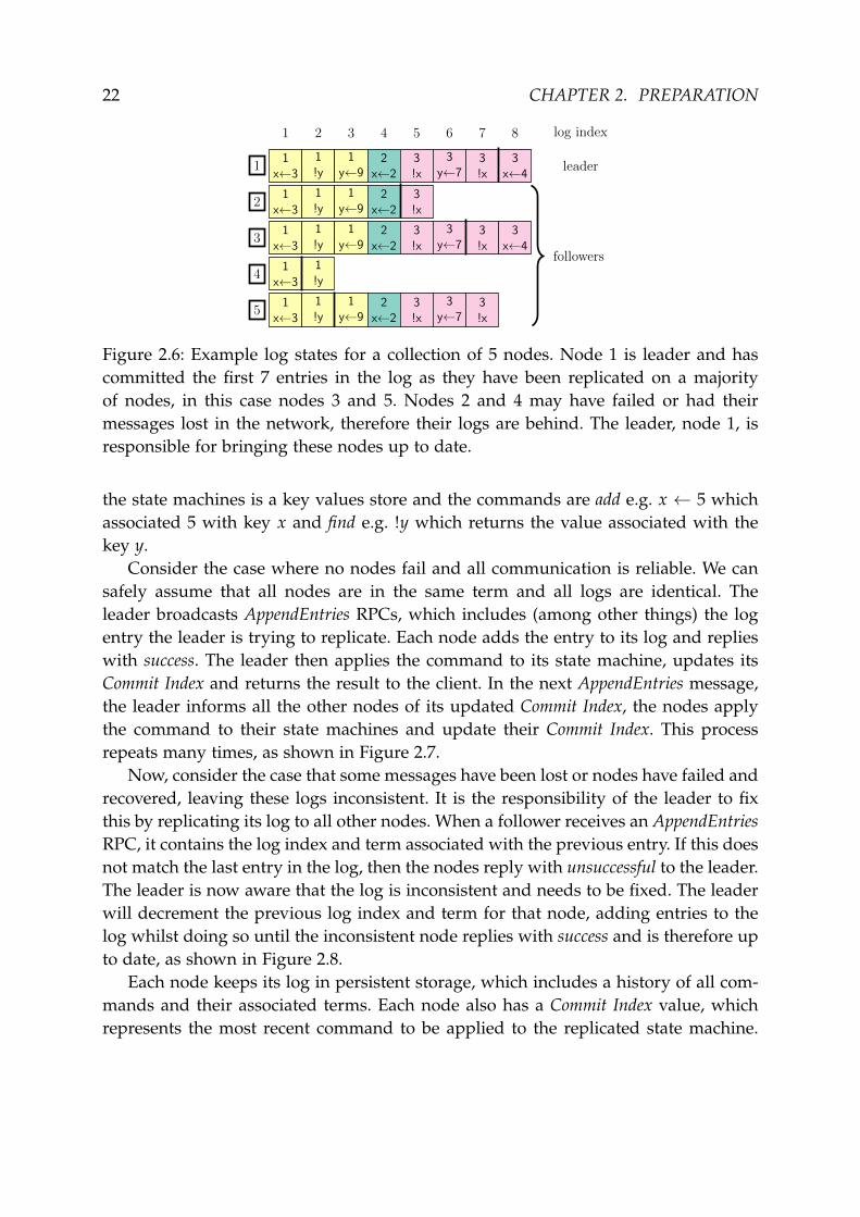
Figure 2.6: Example log states for a collection of 5 nodes. Node 1 is leader and hascommitted the first 7 entries in the log as they have been replicated on a majorityof nodes, in this case nodes 3 and 5. Nodes 2 and 4 may have failed or had theirmessages lost in the network, therefore their logs are behind. The leader, node 1, isresponsible for bringing these nodes up to date.
the state machines is a key values store and the commands are add e.g. x ← 5 whichassociated 5 with key x and find e.g. !y which returns the value associated with thekey y.
Consider the case where no nodes fail and all communication is reliable. We cansafely assume that all nodes are in the same term and all logs are identical. Theleader broadcasts AppendEntries RPCs, which includes (among other things) the logentry the leader is trying to replicate. Each node adds the entry to its log and replieswith success. The leader then applies the command to its state machine, updates itsCommit Index and returns the result to the client. In the next AppendEntries message,the leader informs all the other nodes of its updated Commit Index, the nodes applythe command to their state machines and update their Commit Index. This processrepeats many times, as shown in Figure 2.7.
Now, consider the case that some messages have been lost or nodes have failed andrecovered, leaving these logs inconsistent. It is the responsibility of the leader to fixthis by replicating its log to all other nodes. When a follower receives an AppendEntriesRPC, it contains the log index and term associated with the previous entry. If this doesnot match the last entry in the log, then the nodes reply with unsuccessful to the leader.The leader is now aware that the log is inconsistent and needs to be fixed. The leaderwill decrement the previous log index and term for that node, adding entries to thelog whilst doing so until the inconsistent node replies with success and is therefore upto date, as shown in Figure 2.8.
Each node keeps its log in persistent storage, which includes a history of all com-mands and their associated terms. Each node also has a Commit Index value, whichrepresents the most recent command to be applied to the replicated state machine.

2.3. RAFT PROTOCOL 23
11
x←3
1!y
21
x←3
1!y
31
x←3
1!y
1y←9
1 2 3
1x←3
1!y
1y←9
1x←3
1!y
1x←3
1!y
1y←9
1y←9
1 2 3
1x←3
1!y
1y←9
1x←3
1!y
1y←9
1x←3
1!y
1y←9
1 2 3
1x←3
1!y
1y←9
1x←3
1!y
1y←9
1x←3
1!y
1y←9
1 2 3 log index
leader
followers
Figure 2.7: Example of node 1 committing y← 9 in term 1 at index 3. All nodes’ logsare identical to start with. From right to left: node 1 receives y← 9 from the consensusmodule and appends it to its log. Node 1 dispatches AppendEntries to nodes 2 and 3.These are successful so node 1 updates its commit index (thick black line) to 3, appliesthe command to its state machine and replies to the client. A later AppendEntriesupdates the commit indexes of nodes 2 and 3.
When the Commit Index is updated, the node will pass all commands between thenew and old Commit Index to the state machine.
2.3.3 Safety and Extra Conditions
To ensure safety we must augment the above description with the following extraconditions:
Since the leader will duplicate its log to all other logs, this log must include allprevious committed entries. To achieve this, Raft imposes further constraints on theprotocol detailed so far. First, a node will only grant a vote to another node if its logis at least as up-to-date (defined as either having a last entry with a higher term or, ifterms are equal, a longer log).
The leader node is responsible for replicating its log to all other nodes, includingcommitting entries from the current term and from previous terms. Currently, how-ever, it is possible to commit an entry from a previous term and for a node withoutthis entry to be elected leader and overwrite this (as demonstrated in Figure 2.9).Therefore a leader can only commit an entry from a previous term if it has alreadycommitted an entry from this current term.
The protocol provides linearisable semantics [12], guaranteeing that a commandis committed between the first time a command is dispatched and the first successfulresponse. The protocol doesn’t guarantee a particular interleaving of client requests,but it does guarantee that all state machines will see commands in the same order. Theprotocol assumes that if a client does not receive a response to its request within itsClient Timeout or the response is negative, it will retry this request until successful. Toprovide linearisable semantics, we must ensure that each command is applied to eachstate machine at most once. To address this, each client command has an associated

24 CHAPTER 2. PREPARATION
11
x←3
4!y
4y←9
5x←2
5!x
6y←7
6!x
6x←4
21
x←3
4!y
4y←9
5x←2
5!x
6y←7
6!x
31
x←3
4!y
4y←9
5x←2
5!x
6y←7
6!x
6x←4
7y←5
7!y
41
x←3
4!y
4y←9
4!x
4y←7
51
x←32
x←22!x
2y←7
3!x
3x←5
3!x
3y←4
3y←3
1 2 3 4 5 6 7 8 9 10 log index
leader
followers
(a) Initial state of logs
11
x←3
4!y
4y←9
5x←2
5!x
6y←7
6!x
6x←4
21
x←3
4!y
4y←9
5x←2
5!x
6y←7
6!x
31
x←3
4!y
4y←9
5x←2
5!x
6y←7
6!x
6x←4
41
x←3
4!y
4y←9
4!x
4y←7
51
x←32
x←22!x
2y←7
3!x
3x←5
3!x
3y←4
3y←3
7y←5
7!y
1 2 3 4 5 6 7 8 9 10
(b) bringing node 3 up-to-date
11
x←3
4!y
4y←9
5x←2
5!x
6y←7
6!x
6x←4
21
x←3
4!y
4y←9
5x←2
5!x
6y←7
6!x
31
x←3
4!y
4y←9
5x←2
5!x
6y←7
6!x
6x←4
41
x←3
4!y
4y←9
4!x
4y←7
51
x←32
x←22!x
2y←7
3!x
3x←5
3!x
3y←4
3y←3
6x←4
1 2 3 4 5 6 7 8 9
(c) bringing node 2 up-to-date
11
x←3
4!y
4y←9
5x←2
5!x
6y←7
6!x
6x←4
21
x←3
4!y
4y←9
5x←2
5!x
6y←7
6!x
6x←4
31
x←3
4!y
4y←9
5x←2
5!x
6x
6x
6x
41
x←3
4!y
4x←2
4!x
4y←7
51
x←32
x←22!x
2y←7
3!x
3x←5
3!x
3y←4
3y←3
4y←9
5x←2
5!x
6y←7
6!x
6x←4
1 2 3 4 5 6 7 8 9
(d) bringing node 4 up-to-date
11
x←3
4!y
4y←9
5x←2
5!x
6y←7
6!x
6x←4
21
x←3
4!y
4y←9
5x←2
5!x
6y←7
6!x
6x←4
31
x←3
4!y
4y←9
5x←2
5!x
6x
6x
6x
41
x←3
4!y
4y←9
5x←2
5!x
6y←7
6!x
6x←4
51
x←3
4!y
4y←9
5x←2
5!x
6y←7
6!x
6x←4
1 2 3 4 5 6 7 8
(e) bringing node 5 up-to-date
Figure 2.8: Example of leader, node 1, using AppendEntries RPCs to bring the logs ofnodes 2-5 upto a consistent state. From top right to bottom left:(b) node 1 has just become the leader of term 6, it dispatches AppendEntries with< PrevLogIndex, PrevLogTerm >=< 8, 6 > and only node 3 is consistent so it removesits extra entries;(c) node 1 retries AppendEntries with < 7, 6 > to nodes 2, 4 and 5, and only node 2 isconsistent so appends < 8, 6 >;(d) now node 1 can commit the entry at index 8 and next AppendEntries is < 2, 4 >
and node 4 removes incorrect entries index 3-5 and appends new entries;(e) the final AppendEntries is < 1, 1 > and node 5 is finally consistent.

2.3. RAFT PROTOCOL 25
11
x←3
2!y
21
x←3
31
x←3
3y←2
3x←1
3!x
1 2 3
1x←3
2!y
1x←3
1x←3
3y←2
3x←1
3!x
2!y
1 2
1x←3
2!y
1x←3
3y←2
3x←1
3!x
1x←3
2!y
1 2 3 4
1x←3
3y←2
3x←1
3!x
1x←3
3y←2
3x←1
3!x
1x←3
3y←2
3x←1
3!x
1 2 3 4
Figure 2.9: Example of Leader Completeness violation, without the extra conditionon leadership. From left to right: It is term 4 and node 1 is leader whilst node 3 hasfailed. The leader, node 1 is replicating its log to node 2 and thus commits !y at index2 from term 2. Node 1 then fails and node 3 recovers and becomes leader in term 5,node 3 replicates its log to nodes 1 and 2, thus overwritting !y at index 2.
serial number. Each consensus module caches the last serial number processed fromeach client and response given. If a consensus module is given the same commandtwice, then the second time it will simply return the cached response. The protocolwill never give a false positive, claiming that a command has been committed when itin fact has not but the protocol may give false negatives, claiming that a command hasnot been committed when in fact it has. To address this, the client semantics specifythat each client must retry a command until it has been successfully committed. Eachclient may have at most one command outstanding at a time and commands must bedispatched in serial number order.
The Raft authors claim that the protocol described provides the guarantees inFigure 2.10 for distributed consensus.
Election Safety: at most one leader can be elected in a given termLeader Append-Only: a leader never overwrites or deletes entries in its log; itonly appends new entries.Log Matching: if two logs contain an entry with the same index and term, thenthe logs are identical in all entries up through the given index.Leader Completeness: if a log entry is committed in a given term, then that entrywill be present in the logs of the leaders for all higher-numbered terms.State Machine Safety: if a node has applied a log entry at a given index to its statemachine, no other server will ever apply a different log entry for the same index.
Figure 2.10: Raft’s guarantees to provide distributed consensus

26 CHAPTER 2. PREPARATION
2.4 Requirements Analysis
This project aims to evaluate the Raft consensus algorithm as described in the previoussection. We believe that in order to evaluate the protocol across a range of networkenvironments, we must not only implement the full Raft consensus protocol but alsobuild a simulation framework around it to allow us to fully explore what the protocolhas to offer. Beyond evaluating the performance of the protocol, we were keen touse our simulation traces to catch subtle bugs in our implementation (or even theprotocol specification) which may only occur once in 10,000 or even 100,000 traces.Our insight was that we could use our holistic view of the cluster from the simulator,to ensure that all nodes’ perspectives of the distributed system were consistent withthe protocol. For this reason we designed our own simulation framework instead ofopting for traditional event-based simulations like ns3 or OMNeT++ [37].
We divided the development up into the following phases:
1. Simple event simulation – Build a simple event-based simulator which takes asan argument a number of nodes, simulates these nodes sending simple messagesto each other and responding after random timeouts.
2. Raft leader election at start-up – Implement Raft’s basic leader election protocolby transmitting the RequestVote RPC, terminating the simulation once a leaderhas been established.
3. Raft leader election with failures – Simulate Raft nodes failing and recovering,differentiating clearly between state on volatile and non-volatile storage. Imple-ment the heartbeat functionality of the AppendEntries RPC.
4. Example fault tolerant application – Build an example application for testingRaft. This is a distributed key-value store.
5. Raft log replication – Implement the full AppendEntries RPC, testing the consen-sus protocol using the example application.
6. Client interaction – Simulate clients trying to processes their workloads, imple-ment leader discovery and command commit.
7. Safety model – Model the behaviour of Raft in SPL and compile to OCaml.
8. Invariant checking – Express the protocol’s invariants (Figure 2.10) in OCamland run simulation traces through the checker to ensure no invariants are inval-idated.
2.5. CHOICE OF TOOLS 27
2.5 Choice of Tools
2.5.1 Programming Languages
Our primary development language was OCaml, which is a multi-paradigm, generalpurpose language with a focus on safety, which is key for this project. The core pro-tocol implementation is pure, optimising expressiveness in the type system to restrictthe behaviour of the protocol to its own safety criteria and liberal use of assertionchecks for restricting run-time behaviour. We are not alone in believing OCaml to bea solid choice for distributed systems [34, 23, 30].
Statecall Policy Language (SPL) [22, 21] is a first order imperative language forspecifying non-deterministic finite state automata, such as the one used to definenode behaviour in Raft (Figure 2.2). We have chosen to use SPL due to its ability tobe compiled to either Promela, for model checking in SPIN, or OCaml, to act as asafety monitor at run-time. SPIN is a widely used open source model checker, whichtakes a distributed algorithm specified in Promela and properties specified in LinearTemporal Logic to generate C code verifying that the algorithm satisfies the properties.
2.5.2 Build Systems
For development we used a wrapper around ocamlbuild called corebuild, which pro-vides sensible compiler options for production development1.
2.5.3 Libraries
We used OPAM [35], a source based package manager for OCaml, to manage thelibraries for this project and to later release the project. To minimise dependencies,we depend only on Core, an alternative standard library for OCaml, which has beenthoroughly tested in industry. Although we developed and tested on Unix machines,we limit the dependence on the Unix module to only the Clock.RealTime module, forfuture porting to architectures such as Mirage [23] or Js_of_ocaml2.
2.5.4 Testing
We used OUnit3 for Unit testing the code base as it is a popular choice with plentyof documentation and support available. The unit tests involve multiple test inputs,focusing particularly on edge cases (e.g. empty lists, 0s, negative numbers, etc.) and
1The precise definition of corebuild is available at github.com/janestreet/core/blob/master/corebuild
2ocsigen.org/js_of_ocaml3ounit.forge.ocamlcore.org

28 CHAPTER 2. PREPARATION
asserting that outputs are as expected. These tests are run after successful builds toensure that no regressions have occurred.
The testing framework is composed of building Raft and running a wide range ofsimulations. These were run in a range of environments using Travis CI, a continuousintegration service for open source projects, which runs the test framework againstthe code for each git commit or pull request.
2.6 Summary
We have outlined the Raft consensus algorithm and assumptions under which it op-erates. We explained our motivation for building a simulation framework to evaluatethe protocol. Finally, we closed with our plans for a safety driven approach in OCaml.

Chapter 3
Implementation
3.1 Simulation Framework
The Event-based Simulation for Raft begins with modelling the activity of a collectionof nodes establishing a leader, then terminating, returning the number of time unitstaken to reach agreement on the leader. This phase assumes reliable communicationand always available nodes. From this, we gradually expand functionality and buildup a more elaborate model, reducing the underlying assumptions we are making. Wecalibrate our simulator by reproducing the results from the Raft paper, thus initiallyevaluating the relationship between the time taken for all nodes to agree upon a leaderand the distribution of follower and candidate timeouts.
The simulator supports two modes of operation, Discrete Event Simulation (DES)and Real-time Event Simulation (RES), allowing us to tailor the tradeoff between simu-lation accuracy and time. In the Discrete Event Simulator, each node’s local time willrun arbitrarily fast. Thus we are making primitive assumptions such as that the no-tion of time is quantised including assuming all computation time is negligible andif two packets arrive at a node in the same time unit, they may be served in any or-der. Event-based simulation, particularly DES, will allow us to rapidly iterate over thevast state space of simulation parameters to evaluate performance and detect rarelyoccurring safety violations.
The basic components of the simulator are:
Events Computation to occur at a specific node, at a specific time which can result inmodifications to the state of a node and generate more events, which occur atlater times (i.e. checking timeouts) and may occur on another node (i.e. messagepassing between nodes).
Event List Priority queue of events which are waiting to be simulated, typically im-plemented with data structures such as a splay tree [33], skip lists, calendarqueues [3] or ladder queues.
29

30 CHAPTER 3. IMPLEMENTATION
State Local data for protocol implementation associated with each nodes and client.
Clock Time is a quantised monotonically increasing function where events are in-stantaneous. The purpose of the clock is solely to provide a partial order on theapplication events in the Event list.
Non-determinism Random number generation, required both by the protocol forcontention resolution and for the simulation framework to model packet delay,loss and node failure.
The main body of the simulator iterates over the events from the event list. Eachevent is executed by passing it the state currently associated with that node, then theevent returns both the new state which is associated with that node and any newevents are added to the event list (Figure 3.1).
3.2 Clock
We begin by defining an abstract notion of local time for each node. The purposeof local time for each node is to implement the timeouts traditionally used in asyn-chronous distributed system to approximately determine if a node is live and to buildreliable delivery on unreliable channels. We are able to simulate the variation in localclock speeds by adjusting timeouts accordingly. Every node state and event, has anassociated Time (defined in Figure 3.2).
In the DES, the events are simulated as soon as they are available, as long as thetime ordering is respected. Each node state stores its local time and this is updatedto the event time whenever an event is simulated. In RES, each node state storesa function which evaluates to system time and the events wait in the event queueblocking until it is their time for evaluation. A single simulation module, parametrisedover the implementation of Time (defined in Figure 3.2), implements both DES andRES. This allows us to support both simulation modes with a single simulator, thusmaking the code easier to maintain and avoiding code duplication. Furthermore, thisinterface makes it easy to plug in alternative implementations of Time which could,for example, add noise to FakeTime to simulate different clock speeds.
The module signature of TIME contains two abstract time notions, time whichrepresents the absolute time such as the Unix time or the time since the simulationwas started and span which represents an interval of time. The wait_until functionoffers a blocking wait for real time implementations or instantaneously returns unitfor a DES.
Dynamic erroneous behaviour is handled by assert statements. Figure 3.3 is an ex-tract from the FakeTime module, which implements time as a monotonically increas-ing integer, by initialising the integer to 0 and ensuring all operations only increase

3.2. CLOCK 31
Figure 3.1: Simplified example of DES, simulating Raft Consensus between 3 nodes.Node 3 is leader in term 4 and is dispatching AppendEntries to nodes 1 and 2. Aunified event list is used across the nodes to map time and node ID to events.
its value. This output shows how OCaml runtime terminates when assert statementsevaluate to false. The application of assertion checking to enforce inductively definedinvariants is used systematically throughout our code. This constrains the behaviourof alternative implementations of our signatures, e.g. a poorly designed simulationGUI would not be able to send packets back in time.
In the Raft specification, a term is a monotonically increasing value used to orderevents and messages. A node will only ever need to initialise, increment and compareterms, thus these are the only operations exposed to nodes. As shown in Figure 3.4,each term has one or two phases, the leader election phase and the leadership phase.There will be at most one leader per term and possibly no leaders if consensus isnot reached first time. The previous example demonstrated capturing erroneous be-

32 CHAPTER 3. IMPLEMENTATION
module type TIME =sig
type ttype spanval init : unit -> tval compare : t -> t -> intval add : t -> span -> tval diff : t -> t -> spanval span_of_int : int -> spanval wait_until : t -> unit
endmodule FakeTime : TIMEmodule RealTime : TIME
Figure 3.2: Shared module signature of FakeTime and RealTime.
# let span_of_int x = assert (x>=0); x;;val span_of_int : int -> int = <fun ># span_of_int ( -5);;Exception: "Assert_failure␣// toplevel //:1:20".
Figure 3.3: Demonstration of enforcing time monotonicity.
haviour at run time, but we can do even better by catching errors statically. OCaml’sinterface definitions abstract from implementation details to limit operations to onlythose explicitly made available. The example in Figure 3.5 demonstrates that eventhrough term is implemented as an integer, this detail is not available outside the Termmodule and therefore Term.t is statically guaranteed to only ever increase.
3.3 State
The node and client state is only modified by events during their simulation and thestate is immutable, providing the ability to record and analyse the sequence of state
term 1
election normaloperation
term 2 term 3
no emergingleader
term 4terms
Figure 3.4: Example timeline of terms

3.3. STATE 33
module TERM : sigtype tval succ: t -> tval init: unit -> tval compare: t -> t -> int
end
module Term : TERM = structtype t = int
with comparelet succ = succlet init () = 0
end
Figure 3.5: Use of type system to enforce monotonicity of Term.
changes by maintaining a history of states.Each event takes a representation of state as its last argument and returns a new
representation of state, by applying statecalls to the state using a tick function, as de-fined in Figure 3.6. Internally node state is stored as private record, allowing quickread access but restricting modification to statecalls. Statecalls are a variant type de-noting a safe set of atomic operations on node state, allowing us, for example, tosimulate write-ahead logging. The tick, refresh and init functions are the only meth-ods of generating or modifying node state, either by transformations described bystatecalls, simulating failure by clearing volatile state or initialising a fresh state, re-spectively. This restriction makes many erroneous states simply unrepresentable, thusreducing the state space and making it easier to quantify the valid possible states, aswe do in SPL(§3.8).
module type STATE =functor (Time: TIME) ->functor (Index: INDEX) -> sigtype ttype statecall =| IncrementTerm| Vote of Id.t| StepDown of Index.t| VoteFrom of Id.t
....val tick: statecall -> t -> tval init: Id.t -> Id.t list -> tval refresh: t -> t
end
Figure 3.6: Functor to limit protocol interaction with state to statecalls.

34 CHAPTER 3. IMPLEMENTATION
Network Interface
RAFTCONSENSUSMODULE
ID:7MODE:FollowerTERM:3LEADER:1
REPLICATED LOGCommit Index:5
1 2 3 4 5 6
2[1, 1]x←3
2[2, 1]y←9
3[2, 2]!y
3[2, 3]x←2
4[1, 2]!x
4[1, 3]y←7
KEY VALUE STOREClient# Response
12
23
x=2Success
Key Valuexy
29
RPCs
Figure 3.7: Example node running a key value store using Raft consensus.
3.3.1 Node State
Access to the tick function (defined in Figure 3.6) for modifying node state is mediatedby the StateHandler module, which is responsible for ensuring that no state transitionsviolate the protocol invariants (Figure 2.10) and simulating node failures. The State-Handler module compares each updated node state to the states of all other nodes andall past state to ensure that the perspectives from the nodes are compatible and ableto form a coherent global picture of the distributed system.
For example when a node wins an election in term 7 we can check that no othernode has been leader in term 7 (checking Election Safety from Figure 2.10), at leasta strict majority of nodes have at some time voted for that node in term 7 and allcommitted entries are present in the new leader’s log (checking Leader Completenessfrom Figure 2.10). Or when a follower commits a log entry, we can check that no othernode has committed a different command at the same index (checking State MachineSafety from Figure 2.10) and that the command serial number is strictly greater thenthe last serial number from the corresponding client. To minimise computation, themajority of these checks are implemented inductively, ensuring each monotonic valueis greater then the last.

3.4. EVENTS 35
3.3.2 Client State
Like replica state, Client state access is limited to a set of operations, performed atom-ically by the tick function whose access is mediated by the ClientHandler module.Clients are responsible for not only generating workloads and committing commands,but also checking the client semantics. This proved vital to the project due to the un-derspecification of how Raft handles client requests, detailed in §4.3. Locally eachclient has its own copy of the key-value store which is used to generate expectedresponses for commands. These can then be checked against the responses from theRaft protocol.
3.4 Events
Our insight is that the Raft protocol can be implemented as a collection of events,performing computation in specified temporal and spatial environments. We defineoperators (see opt in Figure 3.8) as a pure mapping from a node state to a new nodestate and a list of new events. A simplified pair of mutually recursive type definitionsseen in Figure 3.8 represent the relationship between events and operators. Polymor-phic over the representation of time, ID’s and state, event relates the time at whichan operator should be simulated, which node should simulate the operator and theoperator itself. The variant RaftEvent is required as OCaml (by default) does not ac-cept recursive type abbreviations. We extend the cases of the variant to simulate othertypes of event such as client events, simulation timeouts and simulated failures.
type (’time , ’id , ’state) event =RaftEvent of (’time * ’id * (’time , ’id , ’state) event)
and (’time , ’id , ’state) opt =’state -> ’state * (’time , ’id , ’state) event list
Figure 3.8: Mutually recursive type definitions of t and event.
All events are queued in the event list as partially applied functions, which per-form computation when applied to state. If the state was mutable, this could be im-plemented by withholding a unit argument, or using the lazy evaluation in OCaml. Tocommunicate, nodes stage events by applying all arguments (except state) to a partic-ular RPC operator, passing this to unicast, multicast or broadcast functions in the Commsmodule to produce the associated events. These functions calculate arrival time fromthe packet delay distribution as well as simulating packet loss or duplication.

36 CHAPTER 3. IMPLEMENTATION
3.5 Event List
Continuing with our theme of protocol safety, our implementation explicitly handlesunexpected behaviours with monads and does not use exceptions except for the SPLsafety monitor. Figure 3.9 uses the option monad1 which forces the caller to patternmatch on the result and explicitly handle the case that the Eventlist is empty. Util-ising the type system for error handling greatly improves the readability of moduleinterfaces and moves the debugging from runtime to compile time. Thus making iteasier to build alternative implementations to test various protocol optimisations andmodifications.
module type Monad = sigtype ’a tval bind: ’a t -> (’a -> ’b t) -> ’b tval return: ’a -> ’a t
end
module Option : Monad = structtype ’a t = None | Some of ’alet bind value f =
match value with| None -> None| Some x -> f x
let return x = Some xend
Figure 3.9: Monad signature and Option monad implementation.
module type EVENTLIST = sigtype itemtype tval head: t -> (item * t) Option.tval add: item list -> t -> tval init: item list -> t
end
Figure 3.10: Signature for data structures implementing Event List.
The Eventlist defined in Figure 3.10 is the most often used data structure in thisproject and is ideal for optimisation due to the limited operations that it is required tosupport. In fact, the only access operation is head, which removes the minimal elementin the data structure and returns an element and the new data structure, if not empty.
1Similar to maybe in Haskell.

3.6. SIMULATION PARAMETERS 37
A naive implementation of EventList would be a sorted list, which clearly providesO(1) for the head function, O(n log n) for init from a list of n items and O(n) to add asingle element in O(n) space. Instead we opted for a splay tree [33], a self-adjustingbinary tree which provides amortized O(log n) for all basic data structure operationbefore applying optimisations for the DES access patterns [11].
module SplayTree (Item: sig type t with compare end) = structtype item = Item.t...
end
Figure 3.11: SplayTree as a functor over Item
As detailed in Figure 3.11, SplayTree is a functor over implementations of Item.SplayTree will return a module satisfying the EVENTLIST signature. However thisabstraction will mean that it is no longer possible to use SplayTree as we have nomechanism of creating things of type Item.t. The solution is a type sharing constraint,which will allow us to expose to the compiler that type item and Event.t are equivalentas shown in Figure 3.12.
module EventList =SplayTree(Event) : EVENTLIST with type item = Event.t
Figure 3.12: Type sharing constraint between item and Event.t
3.6 Simulation Parameters
The simulator accepts a wide range of parameters in the command line interface orconfiguration file. These are detailed in Figure B.1 in the appendix.
The statistical distribution fields such as packet delay or follower timer can begiven as as either a fixed value, an exponential distribution with mean λ and offset,normal distribution with mean µ and standard deviation σ (and options to discardnegative values) or a uniform distribution between minimum and maximum bounds.These parameters are parsed and packaged into a first class module over which theSimulation module is parametrised.
3.7 Non-determinism
Non-determinism is essential for simulating networked systems as well as beingpart of the Raft protocol to avoid pathologically poor performance. The Core stan-

38 CHAPTER 3. IMPLEMENTATION
dard library provides uniform random floating point values2, from this we can thengenerate the required distributions. For example, to simulate the packet delays asa Poisson process we generate the exponentially distributed inter-arrival times asneeded, to limit the space requirements. We transform the provided U ∼ U(0, 1) intoX ∼ Exp(λ) using the following standard result (eq. 3.1) and used the Box-MullerTransform [31] to generate X ∼ N(µ, σ) (eq. 3.2 & eq. 3.3).
X =−1λ
log U (3.1)
Z0 =√−2 ln U1 cos 2πU2 (3.2)
Z1 =√−2 ln U1 sin 2πU2 (3.3)
3.8 Correctness
We modelled the operation of a node participating during Raft consensus using theStatecall Policy Language (SPL) (§2.5.1). The simplest of these automata models thetransitions between the modes of operations as seen in Figure 2.2. The output fromthe SPL is shown in Figure 3.14. Once the models for Raft Consensus were developedin SPL, they were compiled to OCaml for execution alongside the simulations. Eachnode stores a Raft Safety Monitor in its state (detailed in Appendix A) and updates itwith statecalls such as StartElection. The safety monitor terminates execution using aBad_statecall exception if it leaves states defined in the automata like Figure 2.2.
3.9 Summary
We have described our "correct by construction" approach to implementing the Raftalgorithm and an event-based simulator. Using the OCaml module system we havedrawn abstractions between the specific protocol implementation, its safety and thesimulation framework, exposing at each interface only the essential operations. Thismodular design makes it easy to swap implementations, for example testing an al-ternative leader election algorithm. We encoded the protocol invariants and safetychecks at each statecall to ensure that all safety violations are detected in simulationtraces. Furthermore, we have harnessed the expressibility of the type system, allowingus to statically guarantee that no possible Raft implementation will invalidate basicinvariants, such as term monotonically increasing.
2/dev/urandom is used to generate the seed, if it wasn’t available then a value is generated from realtime system parameters like time and processID.

3.9. SUMMARY 39
exception Bad_statecall
type s = [|‘RestartElection|‘StartElection|‘Startup|‘StepDown_from_Candidate|‘StepDown_from_Leader|‘WinElection|‘Recover
]
type tval init : unit -> tval tick : t -> [> s] -> t
Figure 3.13: Example OCaml interface to each node’s run-time monitor, generatedfrom SPL.

40 CHAPTER 3. IMPLEMENTATION
S_seq_14
S_multentry_16
multiple_20=0 (7)
S_or_25
multiple_20=0 (7)
S_or_23
multiple_20=0 (7)
S_multblexit_18
{RestartElection} (8)
S_seq_26
{WinElection} (13)
S_multblexit_11
{StepDown_from_Candidate} (11)
S_multentry_9
{StartElection} (6)
{StepDown_from_Leader} (14)
multiple_13=(multiple_13 + 1) (5)
S_final_2
multiple_13=(multiple_13 + 1) (5)
multiple_20=(multiple_20 + 1) (7)
multiple_20=(multiple_20 + 1) (7) multiple_20=(multiple_20 + 1) (7)
S_either_or_3
multiple_13=0 (5) multiple_13=0 (5)
S_initial_1
{Startup} (1) {Recover} (3)
Figure 3.14: Raft’s mode of operation transitions modelling in SPL.
Chapter 4
Evaluation
In my experience, all distributed consensus algorithms are either:1: Paxos,2: Paxos with extra unnecessary cruft, or3: broken. - Mike Burrows
4.1 Calibration
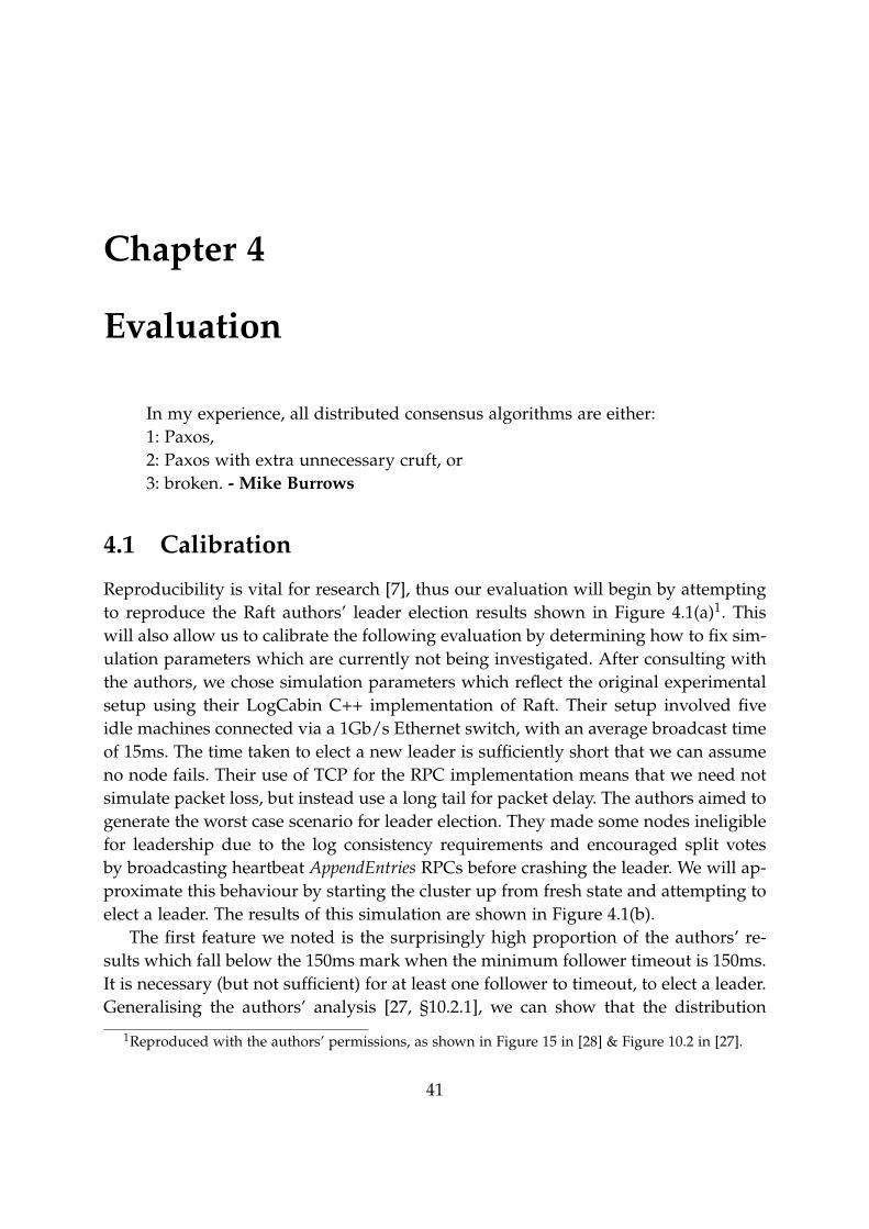
Reproducibility is vital for research [7], thus our evaluation will begin by attemptingto reproduce the Raft authors’ leader election results shown in Figure 4.1(a)1. Thiswill also allow us to calibrate the following evaluation by determining how to fix sim-ulation parameters which are currently not being investigated. After consulting withthe authors, we chose simulation parameters which reflect the original experimentalsetup using their LogCabin C++ implementation of Raft. Their setup involved fiveidle machines connected via a 1Gb/s Ethernet switch, with an average broadcast timeof 15ms. The time taken to elect a new leader is sufficiently short that we can assumeno node fails. Their use of TCP for the RPC implementation means that we need notsimulate packet loss, but instead use a long tail for packet delay. The authors aimed togenerate the worst case scenario for leader election. They made some nodes ineligiblefor leadership due to the log consistency requirements and encouraged split votesby broadcasting heartbeat AppendEntries RPCs before crashing the leader. We will ap-proximate this behaviour by starting the cluster up from fresh state and attempting toelect a leader. The results of this simulation are shown in Figure 4.1(b).
The first feature we noted is the surprisingly high proportion of the authors’ re-sults which fall below the 150ms mark when the minimum follower timeout is 150ms.It is necessary (but not sufficient) for at least one follower to timeout, to elect a leader.Generalising the authors’ analysis [27, §10.2.1], we can show that the distribution
1Reproduced with the authors’ permissions, as shown in Figure 15 in [28] & Figure 10.2 in [27].
41

42 CHAPTER 4. EVALUATION
100 150 300 500 1000 3000 5000 100000%
20%
40%
60%
80%
100%
Cum
ula
tive p
erc
ent
(a) Time taken to elect leader − Author’s results
0 100 200 300 400 500 600 7000%
20%
40%
60%
80%
100%
Time to elect leader (ms)
Cum
ula
tive p
erc
ent
150−151
150−155
150−175
150−200
150−300
12−24
25−50
50−100
100−200
150−300
100 150 300 500 1000 3000 5000 100000%
20%
40%
60%
80%
100%
Cum
ula
tive p
erc
ent
(b) Time taken to elect leader − Discrete simulation (ms granularity)
0 100 200 300 400 500 600 7000%
20%
40%
60%
80%
100%
Time to elect leader (ms)
Cum
ula
tive p
erc
ent
150−151
150−155
150−175
150−200
150−300
12−24
25−50
50−100
100−200
150−300
Figure 4.1: Cumulative distribution function of time to elect leader. Each top plotrepresents the time taken to establish a leader where the follower timeout has varyingdegrees of non-determinism, with the minimal follower timeout fixed at 150ms. Eachbottom plot varies the timeout from T to 2T, for different values of T. The followertimeouts in milliseconds are shown in the legends.

4.1. CALIBRATION 43
of the time the first of s nodes times out, Ts, where the timeout distribution followsf ollowerTimer ∼ U(N1, N2). Ts has a cumulative distribution function, Fs(t) and prob-ability density function fs(t) described below:
Fs(t) =
0 0 < t < N1
1− ( N2−tN2−N1
)s N1 < t < N2
1 otherwise(4.1)
fs(t) =
{s(N2−t)s−1
(N2−N1)s N1 < t < N2
0 otherwise(4.2)
E[Ts] = N1 +N2 − N1
s + 1(4.3)
Figure 4.2 is a plot of the cumulative distribution function (eq. 4.1), this is a base-line for the leader election graphs in Figure 4.1. After discussing our findings withthe authors, it arose that they had been crashing the leader uniformly between Appen-dEntries RPC; hence their results are shifted by ∼ U(0, 75).
150 200 250 3000%
20%
40%
60%
80%
100%
Cu
mu
lative
pe
rce
nt
Distribution of first follower timeout for 5 nodes
0 50 100 150 200 250 3000%
20%
40%
60%
80%
100%
Time to first candidate (ms)
Cu
mu
lative
pe
rce
nt
150−151
150−155
150−175
150−200
150−300
12−24
25−50
50−100
100−200
150−300
Figure 4.2: Cumulative distribution of the time until first election with varying fol-lower timeouts for five nodes (eq. 4.1).
We observe that our simulation generally took longer to establish a leader thanthe authors’ measurements, particularly in the case of high contention. One likely

44 CHAPTER 4. EVALUATION
cause of this is the fact that the authors organised the candidates’ logs such that twonodes were ineligible for leadership. These nodes may timeout like any other anddispatch RequestVotes to the other nodes, but these nodes will never gain a majority,thus reducing the number of possible leaders from five to three and reducing thelikelihood of split votes and multiple rounds of elections. These ineligible candidatesmay still timeout, causing the term in the cluster to increase. Furthermore, these nodeswill reject the last AppendEntries triggering the leader to dispatch more until it fails orbrings the node’s logs up to date. At the time of performing this evaluation, the paperunder-specified the experimental setup used, but emphasised that it was a worst-casescenario. This led to our choices to synchronise nodes and have consistent logs tomaximise the likelihood of split voting.
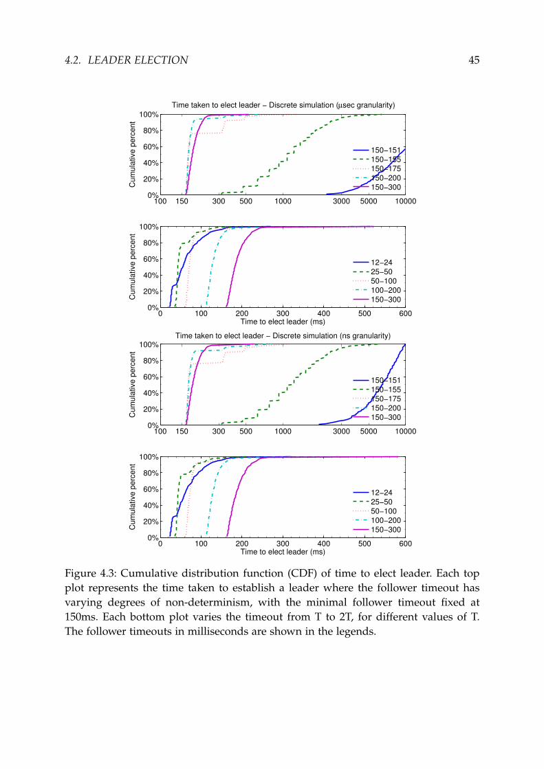
After observing that the stepping in the curve of the 150–155ms case was greatlyexaggerated in comparison with the authors’ results, we were concerned that thequantisation that we used in the DES might have been the cause of this. To test thishypothesis, we repeated the experiment with quanta sizes corresponding to microsec-ond and nanosecond granularity (see Figure 4.3). We observed no significant differ-ence between the three levels of granularity tested except in the 150–151ms case2. De-spite this, we chose to proceed with experiments at the nanosecond granularity dueto a marginal improvement in results and negligible increase in computation time.
4.2 Leader Election
Optimising leader elections
As demonstrated in Figure 4.1, a suitable follower timeout range is needed forgood availability, though the safety of the protocol is independent of timers. If thefollower timer is too small, this can lead to unnecessary leader elections, too largeand followers will be slow to notice a leader failure. The candidate timer must besufficiently large to receive all the RequestVotes responses, whilst being sufficientlysmall to not delay restarting elections. Both follower and candidate timers need to beof a wide enough range to avoid split votes. The leader timer must be smaller thanthe follower timeout. The exact size is a tradeoff between bandwidth usage and speedat which information propagates across the cluster. The conclusion drawn by theprotocol’s authors is that T=150ms is a good conservative timeout in general whenapplied to the rules below. The first condition is known as the timing requirement,where broadcastTime is the average time for a node to send RPCs in parallel to everyserver in the cluster and receive their responses.
2The simulations were terminated after 10s of simulated time.
4.2. LEADER ELECTION 45
100 150 300 500 1000 3000 5000 100000%
20%
40%
60%
80%
100%
Cu
mu
lative
pe
rce
nt
Time taken to elect leader − Discrete simulation (µsec granularity)
0 100 200 300 400 500 6000%
20%
40%
60%
80%
100%
Time to elect leader (ms)
Cu
mu
lative
pe
rce
nt
150−151
150−155
150−175
150−200
150−300
12−24
25−50
50−100
100−200
150−300
100 150 300 500 1000 3000 5000 100000%
20%
40%
60%
80%
100%
Cu
mu
lative
pe
rce
nt
Time taken to elect leader − Discrete simulation (ns granularity)
0 100 200 300 400 500 6000%
20%
40%
60%
80%
100%
Time to elect leader (ms)
Cu
mu
lative
pe
rce
nt
150−151
150−155
150−175
150−200
150−300
12−24
25−50
50−100
100−200
150−300
Figure 4.3: Cumulative distribution function (CDF) of time to elect leader. Each topplot represents the time taken to establish a leader where the follower timeout hasvarying degrees of non-determinism, with the minimal follower timeout fixed at150ms. Each bottom plot varies the timeout from T to 2T, for different values of T.The follower timeouts in milliseconds are shown in the legends.

46 CHAPTER 4. EVALUATION
broadcastTime << candidateTimeout << MTBF
f ollowerTimeout = candidateTimeout ∼ U(T, 2T)
LeaderTimout =T2
Our hypothesis is that the time taken to elect a leader in a contested environmentcould be significantly improved by not simply setting the candidate timer to the rangeof the follower timer. As the authors use the same timer range for candidates andfollowers, in Figure 4.1 we are waiting a minimum of 150ms (and up to twice that)before restarting an election, despite the fact that, on average, a node receives all of itsresponses within 15ms. Figure 4.4 (a) instead sets the minimum candidateTimeout toµ + 2σ. Assuming broadcastTime ∼ N(µ, σ), this will be sufficient 95% of the time. Wecan see that now 99.4% of the time leaders are established within 300ms, compared to54.3% in Figure 4.1.
Increasing the non-determinism in the candidate timeout clearly reduces the num-ber of split votes, but it does so at the cost of increasing the time taken to terminatean election. Our hypothesis is that we can improve the time taken to elect a leaderand make the protocol more resilient to hostile network environments by introduc-ing a binary exponential backoff for candidates who have been rejected by a majorityof replicas. Figure 4.4(b) shows the improvement from enabling binary exponentialbackoff and (c) shows combining the optimisations used in (a) and (b). All optimisa-tions performed considerably better than the orginal implementation, both in termsof time to elect a leader (Figure 4.4) and load on the network (Figure 4.5). Thoughthe binary expontial backoff (b) and combined optimisations (c) took longer to electa leader than the fixed reduction optimisation, they both further reduced the load onthe network (Figure 4.5).
Tolerance to packet loss, delay, reordering & duplication
All tests so far have accounted for packet delay and re-ordering. In Figure 4.4, eachpacket was delayed by delay ∼ N(7ms, 2ms), since each packet delay is computed in-dependently, packet re-ordering is implicit. Our simulator provides options for packetloss and duplication and the protocol remains safe, though performance in the face ofpacket loss could be greatly improved by simple retransmission where an acknowl-edgement of receipt is not received (if not already handled by the transport layerprotocol).

4.2. LEADER ELECTION 47
100 150 200 250 300 350 4000%
20%
40%
60%
80%
100%
Time without leader (ms)
Cum
ula
tive p
erc
ent
(a) Time taken to elect leader − Fixed reduction optimisation
150−151
150−155
150−175
150−200
150−300
100 150 300 500 1000 3000 5000 100000%
20%
40%
60%
80%
100%
Time without leader (ms)
Cum
ula
tive p
erc
ent
(b) Time taken to elect leader − Exponential backoff optimisation
150−151
150−155
150−175
150−200
150−300
100 150 200 250 300 350 4000%
20%
40%
60%
80%
100%
Time without leader (ms)
Cum
ula
tive p
erc
ent
(c) Time taken to elect leader − Combining optimisations
150−151
150−155
150−175
150−200
150−300
Figure 4.4: Investigating the impact of alternative candidate timeouts, keeping therange of follower timeouts fixed:(a) sets candidate timeout to X ∼ U(23, 46)(b) enables binary exponential backoff for candidate timeout(c) combines the optimisations from (a) and (b)The follower timeouts in milliseconds are shown in the legends.

48 CHAPTER 4. EVALUATION
0
250
500
750
1000
1250
1500
A B C D
Nu
mb
er
of
Pa
cke
ts
Network load for leader election
Figure 4.5: Box plot showing effect of candidate timer optimisations on network trafficwhen electing a leader:(A) original setup, as seen in Figure 4.1;(B) fixed reduction optimisation, as seen in Figure 4.4(a);(C) exponential backoff optimisation, as seen in Figure 4.4(b); and(D) combining optimisations, as seen in Figure 4.4(c).

4.3. LOG REPLICATION AND CLIENT SEMANTICS 49
Resilience in the face of diverse network environments
Our analysis so far has been limited to considering a cluster of nodes directly con-nected via an idle network, since packet loss, delay and failure are all assumed to beindependent of the nodes and links involved. This topology is shown in Figure 4.6(a).
Suppose we instead deployed Raft on a network such as the one shown in Fig-ure 4.6(c), where the replicated state machine is a file synchronization applicationworking across a user’s devices such as four mobile devices and a cloud VM. Themobile devices will often be disconnected from the majority of other devices, thusrunning election after election without being able to gain enough votes. When thesedevices rejoin the network, they will force a new election as their term will be muchhigher than the leader. This leads to frequently disconnected devices becoming theleader when reattached to the network, thus causing regular unavailability of the sys-tem when they leave again.
In this setup it would be preferable for the cloud VM to remain leader, unlessseveral of the other devices often share networking that is disconnected from theinternet. We note that if this limitation is a problem for a specific application, it is likelythat the Raft’s model, of providing strong consistency at the cost of availability, maybe unsuitable for that application. In our example topology for a file synchronizationapplication over a user’s devices across the edge network and cloud, a more suitableconsistency model is likely to be BASE.
It is also interesting to consider the impact of a single node being behind an asym-metric partition such as a NAT box or firewall (Figure 4.6(b)). This node will re-peatedly re-run elections as it will not be able to receive incoming messages, eachRequestVotes will have a higher term than the last, forcing the leader to step down.This will prevent the cluster from being able to make progress.
A further challenge for the protocol is modern heterogeneous networks as shownin Figure 4.6(d), the high levels of clustering (e.g. at the rack, switch and datacenterlevels) may exacerbate the problem of split votes and network partitions.
4.3 Log Replication and Client Semantics
During the evaluation of the protocol, we noted that the client commit latency of thesystem can be improved by employing the following modifications and optimisations.
Client request cache
The Raft authors argue that linearisable semantics for client commands to the statemachine are achieved by assigning all commands a sequential serial number whencommitted to the cluster by a client. The state machine then caches the last serial

50 CHAPTER 4. EVALUATION
Figure 4.6: Example diverse network topologies: (a) the original deployment; (b) theasymmetric link; (c) the disconnected edge nodes; and (d) the clustered network.
number for each client along with its corresponding response. This is referred to asthe client request cache. Thus when a client retransmits a request, if the serial numberof the committed command is found in the cache, the command is not reapplied tothe machine and the cached response is returned. This assumes that commands arecommitted to the state machine in order of serial number; thus each client is limitedto at most one outstanding request.
Our first approach, implied by the paper at the time, was to handle this completelyat the state machine level, i.e. a command’s serial number and the state machine cacheare abstracted from the consensus module so all client requests are added to the logregardless of serial number. First, we observed logs being populated with repeatedsequential commands. This reduces performance, but is safe as the command willonly by applied to each state machine once. The greater challenge was the questionof whether the state machine should handle commands whose serial numbers areneither the same as the last serial number or the successor. Commands with lowerserial numbers can arrive from client retransmission or network duplication and net-work delay. Our state machine simply ignores these commands since we know thatthe client cannot possible be waiting for a response. Commands with a higher serialnumber (but not the successor) can only occur where a client has given up on com-mitting a command and tried to commit the next command. We deal with this byrequiring clients to continue retrying commands until successful. The potential forlarge numbers of extraneous entries from this approach leads us to optimise this byexposing serial numbers to the consensus module, which can now use a fast discard orfast response in response to a client’s request.

4.3. LOG REPLICATION AND CLIENT SEMANTICS 51
Inspired by the approach taken by Viewstamped Replication [26], we moved theclient request cache to the consensus module and abstracted it from the state machine.For each incoming request to the leader, the leader looks up the client ID in the clientrequest cache:
• If the requested serial number is less then the last serial number, we can ignorethe command, as the client must have already received a response.
• If the requested serial number is the same as the last serial number, we replywith the cached response if present.
• If the requested serial number is successor of the last serial number, the com-mand can be added to the log and the last serial number updated. Later, oncethe command is committed to the state machine, the response can be cachedalongside the serial number.
But how can it be safe to only store the last serial number and response, when entriescan removed from the log? If any node has ever seen a serial number greater than anyothers last serial number, then the cached response will never be needed as the clientmust have received the response from that committed entry. This positioning of theclient request cache introduced a livelock bug, which we later address (§4.3).
Client commit latency
As expected, the vast majority of client commands were committed with a latency ofapproximately BroadcastTime+RTT, where RTT refers to the round trip time betweenthe client and the leader. A small minority of commands took considerably longer,most commonly representing leader failure and subsequent new leader election. Asignificant overhead was observed by clients waiting for responses from failed nodesduring leader discovery. Unlike the other RPC’s used by Raft, the client commit timer,which is used by clients to retransmit requests to nodes, is much higher than theRTT because the client must wait whilst the leader replicates the client command tothe nodes in the cluster. Introducing a ClientCommit leader acknowledgement wouldallow us to split this into two distinct timers, the first which is just above RTT handlesretransmitting normal ClientCommit requests, whilst the second is used after the clienthas received a leader acknowledgement and is much higher to allow the node time toreplicate the request.
Leader discovery protocol
The authors recommend contacting nodes randomly to discover which node is theleader and try another node at random if the leader appears to have failed. We chose

52 CHAPTER 4. EVALUATION
to instead contact nodes using round robin to reduce the system’s non-determinismand thus make it easier to validate the simulation traces. We recommend retrying theleader before moving back to trying other nodes. This is because if the client has notheard from the leader it could simply be due to network delay or loss. Otherwise,even if the leader has failed, it may have recovered since. If it has then it is more likelythan other nodes to win an election due to the extra condition on elections (§2.3.3).Our recommendations for leader discovery approach are:
• if the target application is highly latency sensitive, we suggest an approach suchas broadcasting ClientCommit to all nodes or having a leader broadcast to clientswhen they come into power.
• if the target application is highly traffic sensitive, we suggest clients back offwhen nodes do not know which node is the leader as it is likely that there is noleader.
Commit-blocking livelock
We believe we have observed permanent livelock in our simulation trace caused bythe interaction between the extra condition on commitment (detailed in §2.3.3) and theplacement of the client request cache (detailed previously). The situation described inFigure 4.7 is one example of this livelock. Figure 4.7 shows this livelock when thereis only one client, but we believe this can also occur when there are multiple suchclients. We recommend that if a client request is blocked by the extra condition oncommitment, the leader should create a no-op entry in its log and replicate this acrossthe cluster, as shown in Figure 4.7. Later, when optimising the handling of read onlycommands, we implemented the authors’ suggestion of appending a no-op at the startof each leadership term which is also sufficient to fix this problem.
4.4 Testing
We have extensively tested this project throughout the implementation, making par-ticularly effective use of static typing. Where erroneous behaviour cannot be detectedat compile time, we utilised unit testing specific modules with OUnit, assertion check-ing throughout the code, automated checking for each simulation trace and checkingeach node’s activity against a safety monitor in SPL. All of these were checked ina range of environments using Travis CI, a continuous integration service for opensource projects, which runs the test framework against the code for each git commitor pull request.
Assertions are used liberally throughout the code base. This means that safetychecks are constantly being made as the code runs and so any runtime errors which

4.4. TESTING 53
11
x←3
2!y
21
x←3
31
x←3
1 2
1
21
x←3
31
x←3
3!y
1x←3
2!y
1 2
11
x←3
2!y
21
x←3
2!y
31
x←3
2!y
1 2
11
x←3
2!y
4NOP
21
x←3
2!y
31
x←3
2!y
1 2 3
11
x←3
2!y
4NOP
21
x←3
2!y
4NOP
31
x←3
2!y
4NOP
1 2 3
11
x←3
2!y
4NOP
21
x←3
2!y
4NOP
31
x←3
2!y
4NOP
1 2 3
Figure 4.7: Example of livelock and our proposed solution. Top row from left to right:It is term 2 and node 1 as leader is trying to commit !y at index 2. Node 1 failedbefore replicating !y to another node and node 3 is now trying to commit !y in term3. Node 3 failed before replicating !y to another node and node 1 is now leader interm 4. Node 3 recovers and node 1 replicates !y to it. No node will be able to commit!y until they commit an entry from their own term but the client will not send newentries until !y is committed. The client retries !y but since it is already in the logs,it is ignored by the nodes and the cluster will not be able to make progress. Bottomrow: node 1 creates a no-op and replicates it across the nodes, so it can now commit!y.

54 CHAPTER 4. EVALUATION
Figure 4.8: Screenshot of Travis CI web GUI for testing git commit history.
may have slipped through can be caught near the source rather than propagatingthrough the code. This made locating the source of errors much easier and also helpsin assessing the safety of the protocol as any invalid behaviour will be checked forand caught rather than create erroneous results.
As an additional, high level form of testing the calibrations run against the refer-ence implementation results from the Raft paper (§4.1) were helpful in determiningthat the behaviour exhibited by this implementation was consistent with how theprotocol is expected to behave.
4.5 Summary
The complexity of the project far exceeded our expectations. Nevertheless we met allof the success criteria of the project including one of our optional extensions by usingour work to propose a range of optimisations to the protocol. The project has been agreat success: we have implemented the Raft consensus protocol and used our simula-tion framework to ensure that protocol operates in asynchronous environments withunreliable communication. Our key value store provides strong consistency from thelinearisable client semantics and a simple protocol wrapper allows our implementa-tion to be run as a real-world implementation. Our implementation is able to makeprogress whilst the majority of nodes are available, with the patch described in §4.3.

Chapter 5
Conclusion
During the course of this project, a strong community has built up around Raft withover 20 different implementations in languages ranging from C++, Erlang and Java toClojure, Ruby and Python. The most popular implementation, go-raft, is the founda-tion of the service discovery and locking services used in CoreOS1 as well as beingdeployed in InfluxDB2 and Sky3. Distributed consensus is never going to be simpleand Raft’s goal of being an understandable consensus algorithm aims to address aclear need in the community.
In a well-understood network environment, the protocol behaves admirably; pro-vided that suitable protocol parameters such as follower timeouts and leadership dis-covery methods have been chosen. As demonstrated in the evaluation, our simulatoris a good approximation to Raft’s behaviour and is a useful tool for anyone planningto deploy Raft to rapidly evaluate a range of protocol configurations on their specificnetwork environment. Despite this, further work is required on the protocol before itwill be able to tolerate modern internet-scale environments, as demonstrated in ourevaluation. In particular, a cluster can be rendered useless by a frequently discon-nected node or a node with an asymmetric partition (such as behind a NAT).
5.1 Recommendations
We would recommend the following modifications/implementation choices to futureimplementations of the Raft Consensus protocol and subsequent deployments:
• Separation of follower and candidate timeouts – We demonstrated (§4.2) signif-icant performance improvements from the separation of follower and candidatetimers, allowing us to set them more appropriately for their purposes. We also
1coreos.com2influxdb.org3skydb.io
55

56 CHAPTER 5. CONCLUSION
demonstrated that applying a binary exponential backoff to the candidate timeralso provides significant performance benefits.
• ClientCommit leader acknowledgement – We addressed the high cost of nodefailure on the client leader discovery protocol, by introducing a ClientCommitleader acknowledgement. This would allow the Client commit timer to be re-duced to slightly above RTT and when the client receives the new leader ac-knowledgement it can backoff, setting a much higher timer to give the leadertime to replicate the command (detailed in §4.3).
• Leader discovery protocol – Depending on intended tradeoff between the clientlatency and traffic: query nodes in a random or round robin fashion, possiblyasking multiple nodes in parallel or broadcasting queries to all nodes (detailedin §4.3).
• Diverse network topologies – As we have discussed, Raft consensus can experi-ence severe availability difficulties in some network topologies. The authors areconsidering how to address these and it remains a goal for future work.
• Client semantics – It is our understanding, that the use of serial numbers re-stricts each client to at most one outstanding request. Otherwise a later clientcommand could be added to the leader’s log before an earlier one. If the clientwishes to have multiple outstanding requests, they can submit the requests asif from multiple clients. The protocol will no longer guarantee that these com-mands will be executed sequentially, but all state machines will commit thecommands in the same order (detailed in §4.3).
• Read commands – Read commands4 need not be replicated across all nodes. It’ssufficient to execute them only on the leader, assuming that the leader has com-mitted an entry from its term and recently dispatched a successful AppendEntriesto a majority of nodes.
• Commit blocking – We demonstrated a liveness bug (§4.3) from the interactionof the client request cache and the extra condition. We went on to propose asolution by allowing leaders to add no-ops to their logs.
• Client instability – To tolerate client failure and subsequent recovery, clientsneed to store their current serial number and outstanding command on non-volatile storage or take a new client ID. All clients must have distinct ID’s.
4This is referring to any class of commands whose execution is guaranteed to not modify the statemachine.

5.2. FUTURE WORK 57
5.2 Future Work
In the future we would like to extend the project to include:
• Full Javascript interface – Combining our simulation trace visualiser withjs_of_ocaml and an interface for specifying simulation parameters including lossand partitions on a link-by-link basis and failure rates on a per node basis.
• Solutions to liveness challenges of diverse network topologies – evaluate arange of possible approaches and determine if the best is sufficient to make Raftconsensus suitable for building distributed systems between users’ devices onthe edge network [30].
• Comparison to Viewstamped Replication (VR) – Utilise the OCaml modulesystem to implement VR within the same simulation framework and compareperformance.
• Log compaction and membership changes – Implement and evaluate Raft’sproposed solutions for log compaction and membership changes, drawing com-parisons to the approach taken by existing consensus algorithms.
• Byzantine fault tolerant Raft – Taking inspiration from existing literature onByzantine tolerant Multi-Paxos [24], design and implement the first Byzantinetolerant Raft.

58 CHAPTER 5. CONCLUSION

Bibliography
[1] Eric Brewer. CAP twelve years later: How the "rules" have changed. Computer,45(2):23–29, 2012.
[2] Eric A Brewer. Towards robust distributed systems. In Principles of DistributedComputing, page 7, 2000.
[3] Randy Brown. Calendar queues: A fast 0(1) priority queue implementation forthe simulation event set problem. Communications of the ACM, 31(10), 1988.
[4] Mike Burrows. The chubby lock service for loosely-coupled distributed systems.In Proceedings of the 7th symposium on Operating systems design and implementation,pages 335–350, 2006.
[5] Tushar Chandra, Robert Griesemer, and Joshua Redstone. Paxos made live-anengineering perspective (2006 invited talk). In Proceedings of the 26th ACM Sym-posium on Principles of Distributed Computing, volume 7, 2007.
[6] Fay Chang, Jeffrey Dean, Sanjay Ghemawat, Wilson C Hsieh, Deborah A Wallach,Mike Burrows, Tushar Chandra, Andrew Fikes, and Robert E Gruber. Bigtable:A distributed storage system for structured data. ACM Transactions on ComputerSystems (TOCS), 26(2):4, 2008.
[7] Bryan Clark, Todd Deshane, Eli Dow, Stephen Evanchik, Matthew Finlayson,Jason Herne, and Jeanna Neefe Matthews. Xen and the art of repeated research.In Proceedings of the USENIX Annual Technical Conference, pages 47–47, 2004.
[8] Michael J Fischer, Nancy A Lynch, and Michael S Paterson. Impossibility of dis-tributed consensus with one faulty process. Journal of the ACM (JACM), 32(2):374–382, 1985.
[9] Sanjay Ghemawat, Howard Gobioff, and Shun-Tak Leung. The Google file sys-tem. In ACM SIGOPS Operating Systems Review, volume 37, pages 29–43. ACM,2003.
59

60 BIBLIOGRAPHY
[10] Seth Gilbert and Nancy Lynch. Brewer’s conjecture and the feasibility of consis-tent, available, partition-tolerant web services. ACM SIGACT News, 33(2):51–59,2002.
[11] Rick Siow Mong Goh and Ian Li-Jin Thng. Dsplay: An efficient dynamic prior-ity queue structure for discrete event simulation. In Proceedings of the SimTecTSimulation Technology and Training Conference, 2004.
[12] Maurice P Herlihy and Jeannette M Wing. Linearizability: A correctness con-dition for concurrent objects. ACM Transactions on Programming Languages andSystems, 12(3):463–492, 1990.
[13] Patrick Hunt, Mahadev Konar, Flavio P Junqueira, and Benjamin Reed.Zookeeper: wait-free coordination for internet-scale systems. In Proceedings ofthe USENIX annual technical conference, volume 8, pages 11–11, 2010.
[14] Leslie Lamport. The part-time parliament. ACM Transactions on Computer Systems(TOCS), 16(2):133–169, 1998.
[15] Leslie Lamport. Paxos made simple. ACM SIGACT News 32.4, pages 18–25vi,2001.
[16] Leslie Lamport. Generalized consensus and paxos. Microsoft Research, Tech. Rep.MSR-TR-2005-33, 2005.
[17] Leslie Lamport. Fast paxos. Distributed Computing, 19(2):79–103, 2006.
[18] Leslie Lamport and Mike Massa. Cheap paxos. In Proceedings of the InternationalConference on Dependable Systems and Networks, pages 307–314, 2004.
[19] Leslie Lamport, Robert Shostak, and Marshall Pease. The byzantine generalsproblem. ACM Transactions on Programming Languages and Systems (TOPLAS),4(3):382–401, 1982.
[20] Barbara Liskov and James Cowling. Viewstamped replication revisited. Technicalreport, MIT technical report MIT-CSAIL-TR-2012-021, 2012.
[21] Anil Madhavapeddy. Creating high-performance statically type-safe network applica-tions. PhD thesis, University of Cambridge, 2006.
[22] Anil Madhavapeddy. Combining static model checking with dynamic enforce-ment using the statecall policy language. In Proceedings of the 11th InternationalConference on Formal Engineering Methods: Formal Methods and Software Engineering,pages 446–465, 2009.

BIBLIOGRAPHY 61
[23] Anil Madhavapeddy, Richard Mortier, Charalampos Rotsos, David Scott, Bal-raj Singh, Thomas Gazagnaire, Steven Smith, Steven Hand, and Jon Crowcroft.Unikernels: Library operating systems for the cloud. In Proceedings of the eigh-teenth international conference on architectural support for programming languages andoperating systems, pages 461–472. ACM, 2013.
[24] Jean-Philippe Martin and Lorenzo Alvisi. Fast byzantine paxos. In Proceedingsof the International Conference on Dependable Systems and Networks, pages 402–411,2004.
[25] David Mazieres. Paxos made practical. http://www.scs.stanford.edu/~dm/home/papers/paxos.pdf.
[26] Brian M Oki and Barbara H Liskov. Viewstamped replication: A new primarycopy method to support highly-available distributed systems. In Proceedings of theseventh annual ACM Symposium on Principles of distributed computing, pages 8–17,1988.
[27] Diego Ongaro. Consensus: Bridging theory and practice. PhD thesis, StanfordUniversity, 2014 (work in progress). http://ramcloud.stanford.edu/~ongaro/thesis.pdf.
[28] Diego Ongaro and John Ousterhout. In search of an understandable consensusalgorithm. In Proceedings of the USENIX Annual Technical Conference, 2014.
[29] Marshall Pease, Robert Shostak, and Leslie Lamport. Reaching agreement in thepresence of faults. Journal of the ACM (JACM), 27(2):228–234, 1980.
[30] Charalampos Rotsos, Heidi Howard, David Sheets, Richard Mortier, Anil Mad-havapeddy, Amir Chaudhry, and Jon Crowcroft. Lost in the edge: Finding yourway with Signposts. In Proceedings of the third USENIX Workshop on Free and OpenCommunications on the Internet, 2013.
[31] David W Scott. Box–muller transformation. Wiley Interdisciplinary Reviews: Com-putational Statistics, 3(2):177–179, 2011.
[32] Dale Skeen and Michael Stonebraker. A formal model of crash recovery in adistributed system. IEEE Transactions on Software Engineering, (3):219–228, 1983.
[33] Daniel Dominic Sleator and Robert Endre Tarjan. Self-adjusting binary searchtrees. Journal of the ACM (JACM), 32(3):652–686, 1985.
[34] Romain Slootmaekers and Nicolas Trangez. Arakoon: A distributed consistentkey-value store. SIGPLAN OCaml Users and Developers Workshop, 2012.

62 BIBLIOGRAPHY
[35] Frederic Tuong, Fabrice Le Fessant, and Thomas Gazagnaire. OPAM: an OCamlpackage manager. SIGPLAN OCaml Users and Developers Workshop, 2012.
[36] Robbert Van Renesse. Paxos made moderately complex. http://www.cs.cornell.edu/courses/cs7412/2011sp/paxos.pdf, 2011.
[37] András Varga et al. The OMNeT++ discrete event simulation system. In Proceed-ings of the European Simulation Multiconference, volume 9, page 185, 2001.

Appendix A
Raft Specification for Simulation
The following Raft specification has been updated and extended from the originalRaft specification [28] for the purpose of simulating the protocol and testing a rangeof implementation choices.
A.1 State
Persistent State (for all modes of operation)
• Current Term – Monotonically increasing value, initialised at start up and incre-mented over time, used to order messages.
• Voted For – The node which has been voted for in the current term, if any. Thisvalue is cleared each time the current term is updated and once it has been setit cannot be changed, thus each node will only hand out one vote per term.
• Log – The replicated log, each entry includes the client’s command, commandserial number, log index and term.
• Last Log Index & Term – Index and term associated with most recent entry inlog.
• State Machine – The state machine which is being replicated1.
• Commit Index – The index of the last command to be passed to the replicatedstate machine, initialised at startup and monotonically increasing1.
• Client Serial Numbers and responses – For each client, the serial number of thelast command that has been committed to the state machine. Each is initialisedat start-up and monotonically increasing. Associated with each serial number isa cached copy of the response from the state machine.
63

64 APPENDIX A. RAFT SPECIFICATION FOR SIMULATION
• ID – Unique reference to this particular node.
• All Nodes – References (and network addresses) to all other nodes in the cluster.
Volatile State (for all modes of operation)
• Mode – Current mode of operation (as shown in Figure 2.2).
• Timers – Implementation of various timers, dependent on current mode, includ-ing packet re-transmissions and follower, candidate and leader timeouts.
• Time – Function from unit to time, specific implementation depends on if asimulation mode like discrete is being used thus it returns the current simulatedtime or realtime which uses the unit to operate on system local time.
• Leader – The current leader (if known) to redirect client to.
• Safety Monitor – SPL automata to catch run-time behaviour leading to diver-gence from safe protocol NFA.
Volatile State (for candidates)
• Votes Granted – List of nodes who have successfully granted this candidate avote, initialised to empty when election is started/restarted and only appendedto. A pre-appending check ensures that a node isn’t already present in list ensur-ing that votes are only counted once per replica, if network duplicates packets,and asserts that the node’s ID is not present in the Votes Not Granted list.
• Votes Not Granted – List of nodes who have not granted this candidate a vote,initialised to empty when election is started/restarted and only appended to. Apre-appending check ensures that a node isn’t already present in list, ensuringthat votes are only counted once per node, if network duplicates packets, andasserts that the node’s ID is not present in the Votes Granted list.
• Backoff Election Number – Number of elections this Candidate has run whichhave received a rejection from a majority of candidates.
Volatile State (for leaders)
• Next Index – For each node, the leader maintains an overestimate of how con-sistent the node’s log is with its own. This value is initialised to one more thenthe leader last index and denotes which log entries will be included in the nextAppendEntries RPC.
• Match Index – For each node, the leader maintains a safe underestimate of howconsistent the node’s log is with its own. This value is initialised on becomingleader and is monotonically increasing.

A.2. RPCS 65
• Outstanding Client Requests – All requests that have been received and theclient is awaiting responses for (at most one per client).
State for each Client
• Workload – The set of commands and associated serial numbers, that the clientwill attempt to commit.
• Expected Results – Expected outcome of each item in the workload to checkresponses, automatically generated by applying workload to local copy of statemachine.
• Time – Function from unit to time, specific implementation depends on if asimulation mode like discrete is being used, thus it returns the current simulatedtime, or realtime which uses the unit to operate on system local time.
• All Nodes – References (and network addresses) to all nodes in the cluster.
• Leader – Latest node to be selected as leader, if known, or details of how tochoose next node to query.
• Outstanding request – The client’s outstanding commit request, if applicable (atmost one).
• Timer – Implementation of timer, to re-transmit packet when nodes fail or pack-ets are lost.
A.2 RPCs
A.2.1 Append Entries
Arguments: Term, LeaderID, PrevLogIndex, PrevLogTerm, Entries, LeaderCommitIn-dex
Results: Success, TermMethod Body:
1. Term Handling: If packet Term is strictly less then node’s Term then the leaderneeds neutralising so respond with false and current term. If packet Term isstrictly greater then node’s Term then the node needs to update its term andstep down if its current mode is Candidate or Leader, then proceed. If packetTerm is equal to node’s Term then proceed
2. Update Follower Timer: Node resets its follower timer as it’s now heard from avalid Leader so we don’t want the node to timeout

66 APPENDIX A. RAFT SPECIFICATION FOR SIMULATION
3. Leader Discovery: Node updates its leader to LeaderID for redirecting a client
4. Test Log Consistency: Use the packet’s PrevLogIndex and PrevLogTerm to de-termine which of the following consistency states the node’s log is:
(a) Perfect Consistency – The node’s Last Log Index and Term are the sameas PrevLogIndex and PrevLogTerm, so logs are identical (under the logmatching guarantee)
(b) Consistent with surplus entries – An entry with PrevLogIndex and Pre-vLogTerm is present in the node’s log, remove all extra log entries and thenlogs are identical
(c) Inconsistent – An entry with PrevLogIndex is present in the node’s log butits associated term is different
(d) Incomplete – No entry with PrevLogIndex is present in the node’s log asthe node’s log doesn’t have enough entries
If the log consistency test outcome was inconsistent or incomplete, reply withfalse and wait for the leader to retry, otherwise (perfectly consistent or consistentwith surplus), the node’s log is now consistent and ready for new entries
5. Append New Entries: If Entries is non-empty then append the entries to the logand update Last Log index and Term, otherwise, if Entries is empty, this was aheartbeat message so no action needs to be taken
6. Commit Indices: If LeaderCommitIndex is greater than node’s current CommitIndex and less than Last Log index then update Commit Index and apply thelog entries between the old Commit Index and new Commit Index.
A.2.2 Client Commit
Arguments: ClientID, SerialNumber, Class, CommandResults: Successful, LeaderID, Results, ClientID, SerialNumberMethod Body:
1. Check client request cache: Search client request cache for the ClientID, if cor-responding SerialNumber is greater than request SerialNumber then discard. IfserialNumbers are equal, then reply to client with cached response. Otherwiseproceed
2. Leader check – If node is not currently the leader, it responds to the client withUnsuccessful and the ID of the current leader, if known

A.2. RPCS 67
3. Read Commit – If the Class of command is read and the leader has committedan entry from its current term, then the leader can apply the command to thestate machine and reply to client
4. Write Commit – Save the client request, add the new SerialNumber to the clientrequest cache and append entry to log. Broadcast AppendEntries RPCs to allnodes with the new update
5. Application to state machine – When the leader match Index for at least a strictmajority of nodes is at least as high as the command entry, then the leader canupdate its commit Index and apply the command to the state machine
6. Response – The response from the state machine can now be cached in the clientrequest cache, and dispatched to the client
A.2.3 Request Vote
Arguments: Term, CandidateID, LastLogIndex, LastLogTermResults: VoteGranted, TermMethod Body:
1. Term Handling: If packet Term is strictly less then node’s Term then the candi-date needs neutralising so respond with false and current term. If packet Termis strictly greater then node’s Term then the node needs to update its term andstep down if its current mode is Candidate or Leader, then proceed. If packetTerm is equal to node’s Term then proceed
2. Vote Granting: Grant vote to this candidate if:
(a) Mode criteria: node’s current state isn’t Leader
(b) Single Vote per Term: node hasn’t yet handed out its vote for this term (orit was to this candidate)
(c) Safe Condition of Leader Elections: candidate’s log is at least as complete asfollower’s log, hence grant if either the candidate’s last term is greater thannode’s last term or if the last terms are equal, the candidate’s last index isgreater or equal to the follower’s last index
3. Update Follower Timer: If vote has been granted, node resets its follower timeras it’s now heard from a valid candidate so we don’t want the replica to timeout
1The state machine and commit index, need not be persistent. If not persistent then on restartinitialise the state machine and commit Index, then when commit index is updated the state machinewill be brought upto date

Appendix B
Simulation Parameters
68

69
Name DescriptionFollower Timeout Distribution of the Follower TimeoutCandidate Timeout Distribution of the Candidate TimeoutBackoff Enable the binary exponential backoff for Candidate
TimeoutsLeader Timeout Distribution of Leader TimeoutClient Timeout Time client waits for response from nodeWorkload Size Number of commands for the client to commitUnsuccessful Commit De-lay
Time client waits after unsuccessful commit to tryagain
Successful Commit Delay Time client waits after successful commit to try nextcommand
Nodes Number of nodes in the clusterMode Discrete or Realtime SimulationNode Failures Distribution of node failure1
Node Recovery Distribution of time until recovery for nodesPacket Delay Distribution of packet delayPacket Loss Probability of any packet being lostPacket Duplication Probability of any packet being duplicated by the net-
workHistory Store a complete history of the all state changes to
nodesConservative Aggregate requests and dispatch only on epochDebug Enable debugging OutputJSON Enable JSON OutputIteration Number of simulations to runTermination criteria Terminate simulation once a leader has been elected
or all client commands have been committed or timehas exceeded a given value
Figure B.1: Table detailing the available simulation parameters


![Decoupling of Distributed Consensus, Failure Detection and ...mediatum.ub.tum.de/doc/1544917/159195.pdf · For example, in Raft [11], the leader is in charge of serialization of message](https://static.fdocuments.in/doc/165x107/5f4265d03037f331cf4dcab4/decoupling-of-distributed-consensus-failure-detection-and-for-example-in-raft.jpg)

![Canopus: A Scalable and Massively Parallel Consensus Protocol · Raft [33], a consensus algorithm with understandability as its main design goal, and Zab [17], an atomic broad-cast](https://static.fdocuments.in/doc/165x107/5f429372aa4da9089d6c2d17/canopus-a-scalable-and-massively-parallel-consensus-protocol-raft-33-a-consensus.jpg)