ARC-1212_1222__manual
166
ARC-1212/1222 (4/8 Ports PCIe to SAS/SATA RAID Controllers ) SAS RAID Cards USER’S Manual Version: 1.0 Issue Date: April, 2008
Transcript of ARC-1212_1222__manual
ARC-1212/1222(4/8 Ports PCIe to SAS/SATA RAID Controllers )
SAS RAID Cards
USER’S ManualVersion: 1.0Issue Date: April, 2008
Copyright and Trademarks
The information of the products in this manual is subject to change without prior notice and does not represent a commitment on the part of the vendor, who assumes no liability or responsibility for any errors that may appear in this manual. All brands and trademarks are the properties of their respective owners. This manual contains materials protected under International Copyright Conventions. All rights reserved. No part of this manual may be reproduced in any form or by any means, electronic or mechanical, including photocopying, without the written permission of the manufacturer and the author. All inquiries should be addressed to Areca Technology Corporation.
FCC STATEMENT
This equipment has been tested and found to comply with the lim-its for a Class B digital device, pursuant to part 15 of the FCC Rules. These limits are designed to provide reasonable protection against in-terference in a residential installation. This equipment generates, uses, and can radiate radio frequency energy and, if not installed and used in accordance with the instructions, may cause harmful interference to radio communications. However, there is no guarantee that interfer-ence will not occur in a particular installation.
Contents1. Introduction .............................................................. 10
1.1 Overview ....................................................................... 101.2 Features ........................................................................ 12
2. Hardware Installation ............................................... 152.1 Before Your Begin Installation ........................................... 152.2 Board Layout .................................................................. 162.3 Installation ..................................................................... 182.4 SAS Cables .................................................................... 23
2.4.1 Internal Min SAS 4i to SATA Cable ............................... 232.4.2 Internal Min SAS 4i to 4xSFF-8482 Cable ....................... 242.4.3 Internal Min SAS 4i to Internal Min SAS 4i cable ............. 25
2.5 LED Cables ..................................................................... 253. McBIOS RAID Manager .............................................. 31
3.1 Starting the McBIOS RAID Manager ................................... 313.2 McBIOS RAID manager .................................................... 323.3 Configuring Raid Sets and Volume Sets .............................. 333.4 Designating Drives as Hot Spares ...................................... 333.5 Using Quick Volume /Raid Setup Configuration .................... 343.6 Using RAID Set/Volume Set Function Method ...................... 353.7 Main Menu .................................................................... 37
3.7.1 Quick Volume/RAID Setup ........................................... 383.7.2 Raid Set Function ....................................................... 42
3.7.2.1 Create Raid Set .................................................... 433.7.2.2 Delete Raid Set ..................................................... 443.7.2.3 Expand Raid Set .................................................... 45• Migrating ...................................................................... 463.7.2.4 Activate Incomplete Raid Set ................................... 463.7.2.5 Create Hot Spare ................................................... 473.7.2.6 Delete Hot Spare ................................................... 473.7.2.7 Raid Set Information .............................................. 48
3.7.3 Volume Set Function ................................................... 483.7.3.1 Create Volume Set (0/1/10/3/5/6) ........................... 50• Volume Name ................................................................ 51• Raid Level ..................................................................... 52• Capacity ....................................................................... 52• Stripe Size .................................................................... 53• SCSI Channel ................................................................ 54
• SCSI ID ........................................................................ 54• SCSI LUN ...................................................................... 55• Cache Mode .................................................................. 55• Tag Queuing .................................................................. 563.7.3.2 Create Raid30/50/60 (Volume Set 30/50/60) ............ 563.7.3.3 Delete Volume Set ................................................. 573.7.3.4 Modify Volume Set ................................................. 583.7.3.4.1 Volume Growth ................................................... 593.7.3.4.2 Volume Set Migration .......................................... 593.7.3.5 Check Volume Set .................................................. 603.7.3.6 Stop Volume Set Check .......................................... 613.7.3.7 Display Volume Set Info. ........................................ 61
3.7.4 Physical Drives ........................................................... 613.7.4.1 View Drive Information .......................................... 623.7.4.2 Create Pass-Through Disk ....................................... 623.7.4.3 Modify a Pass-Through Disk ..................................... 633.7.4.4 Delete Pass-Through Disk ....................................... 633.7.4.5 Identify Selected Drive ........................................... 64
3.7.5 Raid System Function ................................................. 643.7.5.1 Mute The Alert Beeper ........................................... 653.7.5.2 Alert Beeper Setting ............................................... 653.7.5.3 Change Password .................................................. 663.7.5.4 JBOD/RAID Function .............................................. 673.7.5.5 Background Task Priority ........................................ 673.7.5.6 SATA NCQ Support ................................................. 683.7.5.7 HDD Read Ahead Cache .......................................... 693.7.5.8 Stagger Power On .................................................. 693.7.5.9 Controller Fan Detection ......................................... 703.7.5.10 Auto Activate Raid Set .......................................... 713.7.5.11 Capacity Truncation .............................................. 71
3.7.6 Ethernet Configuration ............................................... 723.7.6.1 DHCP Function ...................................................... 723.7.6.2 Local IP address .................................................... 733.7.6.3 HTTP Port Number ................................................. 743.7.6.4 Telnet Port Number ................................................ 753.7.6.5 SMTP Port Number ................................................. 753.7.6.6 Ethernet Address ................................................... 76
3.7.7 View System Events ................................................... 763.7.8 Clear Events Buffer ..................................................... 773.7.9 Hardware Monitor ....................................................... 773.7.10 System Information .................................................. 78
4. Driver Installation ..................................................... 794.1 Creating the Driver Diskettes ............................................ 794.2 Driver Installation for Windows ......................................... 81
4.2.1 New Storage Device Drivers in Windows 2003/XP-64/Vista .814.2.2 Install Windows 2000/XP/2003/Vista on a SAS/SATA RAID Volume ............................................................................. 81
4.2.2.1 Installation Procedures ........................................... 814.2.2.2 Making Volume Sets Available to Windows System ..... 83
4.2.3 Installing controller into an existing Windows 2000/XP/2003/Vista Installation ................................................... 83
4.2.3.1 Making Volume Sets Available to Windows System ..... 854.2.4 Uninstall controller from Windows 2000/XP/2003/Vista .... 85
4.3 Driver Installation for Linux .............................................. 864.4 Driver Installation for FreeBSD .......................................... 874.5 Driver Installation for Solaris ............................................ 874.6 Driver Installation for Mac X ............................................. 87
5. ArcHttp Proxy Server Installation ............................. 895.1 For Windows................................................................... 905.2 For Linux ....................................................................... 915.3 For FreeBSD ................................................................... 935.4 For Solaris 10 X86 ........................................................... 935.5 For Mac OS 10.X ............................................................. 93
6. Web Browser-based Configuration ........................... 986.1 Start-up McRAID Storage Manager ................................... 98
• Start-up McRAID Storage Manager from Windows Local Administration .................................................................. 99
6.2 SAS RAID controller McRAID Storage Manager .................. 1016.3 Main Menu .................................................................. 1026.4 Quick Function .............................................................. 1026.5 Raid Set Functions ........................................................ 103
6.5.1 Create Raid Set ....................................................... 1036.5.2 Delete Raid Set ........................................................ 1046.5.3 Expand Raid Set ....................................................... 1046.5.4 Activate Incomplete Raid Set ..................................... 1056.5.5 Create Hot Spare ..................................................... 1066.5.6 Delete Hot Spare ...................................................... 1066.5.7 Rescue Raid Set ....................................................... 1076.5.8 Offline Raid Set ........................................................ 107
6.6 Volume Set Functions .................................................... 1076.6.1 Create Volume Set (0/1/10/3/5/6) ............................. 108
• Volume Name .............................................................. 109• Volume Raid Level ....................................................... 109• Capacity ..................................................................... 109• Greater Two TB Volume Support ..................................... 109• Initialization Mode ........................................................ 109• Strip Size .................................................................... 110• Cache Mode ................................................................ 110• Tagged Command Queuing ............................................ 110
6.6.2 Create Raid30/50/60 (Volume Set 30/50/60) ............... 1116.6.3 Delete Volume Set .................................................... 1116.6.4 Modify Volume Set .................................................... 112
6.6.4.1 Volume Growth ................................................... 1136.6.4.2 Volume Set Migration ........................................... 113
6.6.5 Check Volume Set .................................................... 1146.6.6 Stop Volume Set Check ............................................. 115
6.7 Physical Drive .............................................................. 1156.7.1 Create Pass-Through Disk .......................................... 1156.7.2 Modify Pass-Through Disk .......................................... 1166.7.3 Delete Pass-Through Disk .......................................... 1176.7.4 Identify Drive .......................................................... 117
6.8 System Controls ........................................................... 1186.8.1 System Config ......................................................... 118
• System Beeper Setting ................................................. 118• Background Task Priority ............................................... 118• JBOD/RAID Configuration .............................................. 118• HDD Read Ahead Cache ................................................ 119• HDD Queue Depth ....................................................... 119• Stagger Power on ........................................................ 119• Auto Activate Incomplete Raid ....................................... 119• Disk Capacity Truncation Mode ....................................... 120
6.8.2 Ethernet Configuration ............................................. 1206.8.3 Alert By Mail Configuration ....................................... 1216.8.4 SNMP Configuration .................................................. 1226.8.5 NTP Configuration .................................................... 123
• NTP Sever Address ....................................................... 123• Time Zone ................................................................... 124• Automatic Daylight Saving............................................. 124
6.8.6 View Events/Mute Beeper .......................................... 1246.8.7 Generate Test Event ................................................. 1256.8.8 Clear Events Buffer ................................................... 1256.8.9 Modify Password ...................................................... 1256.8.10 Update Firmware ................................................... 126
6.9 Information .................................................................. 1276.9.1 Raid Set Hierarchy .................................................... 1276.9.2 System Information .................................................. 1276.9.3 Hardware Monitor ..................................................... 128
Appendix A ................................................................. 129Upgrading Flash ROM Update Process .................................... 129Upgrading Firmware Through McRAID Storage Manager ........... 130Upgrading Firmware Through nflash DOS Utility ...................... 131Upgrading Firmware Through CLI .......................................... 132
Appendix B .................................................................. 134Battery Backup Module (ARC-6120-BAT-Txx) .......................... 134
BBM Components ........................................................... 134Status of BBM ................................................................ 134Installation .................................................................... 134Battery Backup Capacity .................................................. 135Operation ...................................................................... 135Changing the Battery Backup Module ................................ 136BBM Specifications .......................................................... 136
Appendix C .................................................................. 138SNMP Operation & Installation .............................................. 138
Appendix D .................................................................. 145Event Notification Configurations ........................................ 145
A. Device Event .............................................................. 145B. Volume Event ............................................................. 146C. RAID Set Event .......................................................... 147D. Hardware Monitor Event .............................................. 147
Appendix E .................................................................. 149RAID Concept .................................................................... 149
RAID Set ......................................................................... 149Volume Set ...................................................................... 149Ease of Use Features ......................................................... 150
• Foreground Availability/Background Initialization .............. 150• Online Array Roaming ................................................... 150• Online Capacity Expansion ............................................. 150• Online Volume Expansion .............................................. 153
High availability .................................................................. 153• Global Hot Spares .......................................................... 153• Hot-Swap Disk Drive Support ........................................... 154• Auto Declare Hot-Spare ................................................. 154• Auto Rebuilding ............................................................ 155• Adjustable Rebuild Priority ............................................... 155
High Reliability ................................................................... 156• Hard Drive Failure Prediction ............................................ 156• Auto Reassign Sector ...................................................... 156• Consistency Check ......................................................... 157
Data Protection .................................................................. 157• Battery Backup ............................................................. 157• Recovery ROM ............................................................... 158
Appendix F .................................................................. 159 Understanding RAID .......................................................... 159
RAID 0 ............................................................................ 159RAID 1 ............................................................................ 160RAID 3 ............................................................................ 161RAID 5 ............................................................................ 162RAID 6 ............................................................................ 163RAID x0 .......................................................................... 163JBOD .............................................................................. 164Single Disk (Pass-Through Disk) ......................................... 164

INTRODUCTION
10
1. Introduction
This section presents a brief overview of the SAS RAID controller, ARC-1212/1222 series. (PCIe to SAS/SATA RAID controllers)
1.1 Overview
SAS builds on parallel SCSI by providing higher performance,improving data availability, and simplifying system design. TheSAS interface supports both SAS disk drives for data-intensiveapplications and Serial ATA (SATA) drives for low-cost bulk storageof reference data. The ARC-1212/1222 support directly attach 4/8 SAS ports via one internal /two internal Min SAS connector. Each port on the SAS controllers supports SAS and/or SATA devices.Since there is no expander support on those boards, this can meet the customer inquiry SAS solution (using same enclosure) to replace SATA solution. The ARC-1212/1222 RAID controllers only support directly attach to 4/8 SAS/SATA drives without supporting the expand function.
The ARC-1212/1222 RAID controllers are low-profile PCIe cards, ideal for 1U and 2U rack-mount systems without needing the ex-pansion capability. These controllers utilize the same RAID kernel that has been field-proven in existing external RAID controller products, allowing Areca to quickly bring stable and reliable RAID controllers to the market
Unparalleled Performance The SAS RAID controllers raise the standard to higher performance levels with several enhancements including Intel new high-perfor-mance I/O Processor, a DDR2-533 memory architecture and high performance PCIe x8 Link host interface bus interconnection. The low profile controllers by default support on-board 256MB of ECC DDR2-533 SDRAM memory with optional battery backup moduleThe test result is against overall performance compared to other SAS RAID controllers. The powerful Intel new I/O processors inte-grated 4/8-port SAS I/O ports on chip delivers high performance for servers and workstations.
INTRODUCTION
11
Unsurpassed Data Availability
As storage capacities continue to rapidly increase, users needgreater level of disk drive fault tolerance, which can be implement-ed without doubling the investment in disk drives. The RAID6 can offer fault tolerance greater that RAID 1 or RAID 5 but onlyconsumes the capacity of 2 disk drives for distributed parity data.The SAS RAID controllers with extreme performance RAID 6 engineinstalled provide the highest RAID 6 feature to meet this require-ment. The controller can concurrently compute two parity blocksand get very similar RAID 5 performance. The SAS RAID controllers can also provide RAID levels 0, 1, 10, 3,5, 6, 30, 50, 60, Single Disk or JBOD for maximum configuration flexibility. Its high data availability and protection derives from the following capabilities: Online RAID Capacity Expansion, Array Roaming, Online RAID Level / Stripe Size Migration, Global Online Spare, Automatic Drive Failure Detection, Automatic Failed Drive Rebuilding, Disk Hot-Swap, Online Background Rebuilding, Instant Availability/Background Initialization, Auto Reassign Sector, Redun-dant Flash Image and Battery Backup Module. Greater than Two TB Support allows for very large volume set application in 64-bit environment such as data-mining and managing large databases. Maximum Interoperability
The SAS RAID controller support broad operating system includingWindows Vista/Server 2003/XP/2000, Linux (Open Source), Free-BSD (Open Source), Solaris (Open Source), Mac and more, along with key system monitoring features such as enclosure manage-ment (SGPIO) and SNMP function. Our products and technology are based on extensive testing and validation process; leverage Areca SATA RAID controller field-proven compatibility with operat-ing systems, motherboards, applications and device drivers.
INTRODUCTION
12
Easy RAID Management
The controllers contain an embedded McBIOS RAID manager thatcan access via hot key at M/B BIOS boot-up screen. This pre-boot McBIOS RAID manager can use to simplify the setup and manage-ment of RAID controller. The controller firmware also contains a browser-based McRAID storage manager which can be accessed through the Ethernet port or ArcHttp proxy server in Windows, Linux, FreeBSD and more environments. The McRAID storage man-ager allows local and remote to create and modify RAID set, vol-ume set, and monitor RAID status from standard web browser. The Single Admin Portal (SAP) monitor utility can support one applica-tion to scan multiple RAID units in the network. The Disk Stress Test (DST) utility kicks out disks meeting marginal spec before the RAID unit is actually put on-line for real business.
1.2 Features
Adapter Architecture• Intel 800MHz IOP348 I/O processor with SAS controller• PCIe x8 Link host interface • 256MB on-board DDR2-533 SDRAM with ECC • Write-through or write-back cache support• ARC-1212 supports up to 4 internal SAS/SATA ll HDDs.• ARC-1222 supports up to 8 internal SAS/SATA ll HDDs.• Multi-adapter support for large storage requirements• BIOS boot support for greater fault tolerance• BIOS PnP (plug and play) and BBS (BIOS boot specification) support• Intel RAID engine support extreme performance RAID 6 function• NVRAM for RAID configuration & transaction log• Redundant flash image for adapter availability• Battery Backup Module (BBM) ready (Option)• RoHS Compliant
RAID Features• RAID level 0, 1, 10, 3, 5, 6, 30, 50, 60, Single Disk or JBOD• Multiple RAID selection
INTRODUCTION
13
• Online array roaming• Online RAID level/stripe size migration• Online capacity expansion and RAID level migration simultane- ously• Online volume set growth• Instant availability and background initialization• Automatic drive insertion/removal detection and rebuilding• Greater than 2TB per volume set (64-bit LBA support)• Support spin down drives when not in use to extend service life (MAID)• Support NTP protocol synchronize RAID controller clock over the on board Ethernet port
Monitors/Notification• System status indication through global HDD activity/fault con- nector, individual activity/fault connector, LCD/I2C connector and alarm buzzer• SMTP support for email notification• SNMP support for remote manager• Enclosure management (Serial Bus and SGPIO) ready
RAID Management• Field-upgradeable firmware in flash ROM
In-Band Manager• Hot key "boot-up" McBIOS RAID manager via M/B BIOS• Web browser-based McRAID storage manager via ArcHttp proxy server for all operating systems• Support Command Line Interface (CLI)• API library for customer to write monitor utility• Single Admin Portal (SAP) monitor utility• Disk Stress Test (DST) utility for production
Out-of-Band Manager• Firmware-embedded web browser-based McRAID storage man- ager, SMTP manager, SNMP agent and Telnet function via Ethernet port• API library for customer to write monitor utility• Support Push Button and LCD display panel (option)
INTRODUCTION
14
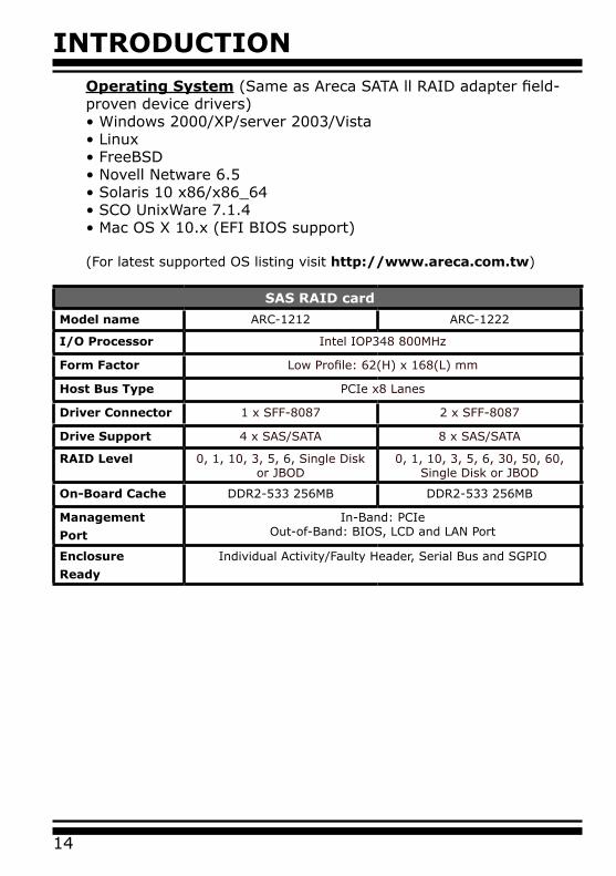
Operating System (Same as Areca SATA ll RAID adapter field-proven device drivers)• Windows 2000/XP/server 2003/Vista• Linux • FreeBSD• Novell Netware 6.5• Solaris 10 x86/x86_64• SCO UnixWare 7.1.4• Mac OS X 10.x (EFI BIOS support) (For latest supported OS listing visit http://www.areca.com.tw)
SAS RAID card
Model name ARC-1212 ARC-1222
I/O Processor Intel IOP348 800MHz
Form Factor Low Profile: 62(H) x 168(L) mm
Host Bus Type PCIe x8 Lanes
Driver Connector 1 x SFF-8087 2 x SFF-8087
Drive Support 4 x SAS/SATA 8 x SAS/SATA
RAID Level 0, 1, 10, 3, 5, 6, Single Disk or JBOD
0, 1, 10, 3, 5, 6, 30, 50, 60, Single Disk or JBOD
On-Board Cache DDR2-533 256MB DDR2-533 256MB
Management
Port
In-Band: PCIeOut-of-Band: BIOS, LCD and LAN Port
Enclosure
Ready
Individual Activity/Faulty Header, Serial Bus and SGPIO
HARDWARE INSTALLATION
15
2. Hardware InstallationThis section describes the procedures for installing the SAS RAID con-trollers.
2.1 Before Your Begin Installation
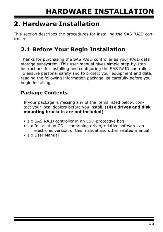
Thanks for purchasing the SAS RAID controller as your RAID data storage subsystem. This user manual gives simple step-by-step instructions for installing and configuring the SAS RAID controller. To ensure personal safety and to protect your equipment and data, reading the following information package list carefully before you begin installing.
Package Contents
If your package is missing any of the items listed below, con-tact your local dealers before you install. (Disk drives and disk mounting brackets are not included)
• 1 x SAS RAID controller in an ESD-protective bag • 1 x Installation CD – containing driver, relative software, an electronic version of this manual and other related manual
• 1 x User Manual

HARDWARE INSTALLATION
16
Connector Type Description
1. (J4) Ethernet Port RJ45
2. (JP2) Individual Fault LED Header 8-pin header
3. (J5) Individual Activity (HDD) LED Header 8-pin header
4. (J6) Global Fault/Activity-Cache Write Pending LED
4-pin header
5. (J2) Battery Backup Module Connector 12-pin box header
6. (J1) Manufacture Purpose Port 10-pin header
7. (J3) I2C/LCD Connector 8-pin header
8. (SCN1) SAS 1-4 Ports for ARC-1212/1222 Min SAS 4i
9. (SCN2) SAS 5-8 Ports for ARC-1222 Min SAS 4i
Table 2-1 , ARC-1212/1222 Connector
Figure 2-1, ARC-1212/1222 SAS RAID Controller
2.2 Board Layout
The controller can support a family included 4/8 ports models with 1/2 internal SFF-8087 connectors. This section provides the board layout and connector/jumper for the SAS RAID controller.
HARDWARE INSTALLATION
17
Tools Required
An ESD grounding strap or mat is required. Also required are stan-dard hand tools to open your system’s case.
System Requirement
The SAS RAID controller can be installed in a universal PCIe slot and requires a motherboard that:
ARC-1212/1222 series SAS RAID controller requires:• Comply with the PCIe x8
It can work on the PCIe x1, x4, x8, and x16 signal with x8 or x16 slot M/B.
Installation Tools
The following items may be needed to assist with installing the SAS RAID controller into an available PCIe expansion slot. • Small screwdriver• Host system hardware manuals and manuals for the disk or enclosure being installed.
Personal Safety Instructions
Use the following safety instructions to help you protect your computer system from potential damage and to ensure your own personal safety.
• Always wear a grounding strap or work on an ESD-protective mat.• Before opening the system cover, turn off power switches and unplug the power cords. Do not reconnect the power cords until you have replaced the covers.
HARDWARE INSTALLATION
18
Electrostatic Discharge
Static electricity can cause serious damage to the electronic com-ponents on this SAS RAID controller. To avoid damage caused by electrostatic discharge, observe the following precautions:
• Do not remove the SAS RAID controller from its anti-static packaging until you are ready to install it into a computer case. • Handle the SAS RAID controller by its edges or by the metal mounting brackets at its each end. • Before you handle the SAS RAID controller in any way, touch a grounded, anti-static surface, such as an unpainted portion of the system chassis, for a few seconds to discharge any built-up static electricity.
2.3 Installation
Use the following instructions below to install a PCIe SAS RAID controller.
Step 1. UnpackUnpack and remove the PCIe SAS RAID controller from the pack-age. Inspect it carefully, if anything is missing or damaged, contact your local dealer.
Step 2. Power PC/Server OffTurn off computer and remove the AC power cord. Remove the system’s cover. For the instructions, please see the computer sys-tem documentation.
Warning:
High voltages may be found inside computer equipment. Before installing any of the hardware in this package or removing the protective covers of any computer equipment, turn off power switches and disconnect power cords. Do not reconnect the power cords until you have replaced the covers.
HARDWARE INSTALLATION
19
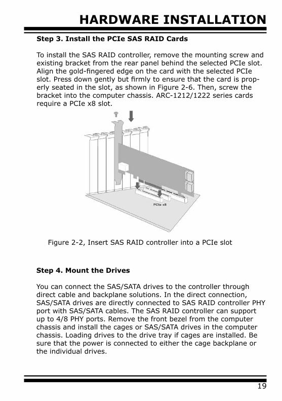
Figure 2-2, Insert SAS RAID controller into a PCIe slot
Step 3. Install the PCIe SAS RAID Cards
To install the SAS RAID controller, remove the mounting screw and existing bracket from the rear panel behind the selected PCIe slot. Align the gold-fingered edge on the card with the selected PCIe slot. Press down gently but firmly to ensure that the card is prop-erly seated in the slot, as shown in Figure 2-6. Then, screw the bracket into the computer chassis. ARC-1212/1222 series cards require a PCIe x8 slot.
Step 4. Mount the Drives
You can connect the SAS/SATA drives to the controller through direct cable and backplane solutions. In the direct connection, SAS/SATA drives are directly connected to SAS RAID controller PHY port with SAS/SATA cables. The SAS RAID controller can support up to 4/8 PHY ports. Remove the front bezel from the computer chassis and install the cages or SAS/SATA drives in the computer chassis. Loading drives to the drive tray if cages are installed. Be sure that the power is connected to either the cage backplane or the individual drives.
HARDWARE INSTALLATION
20
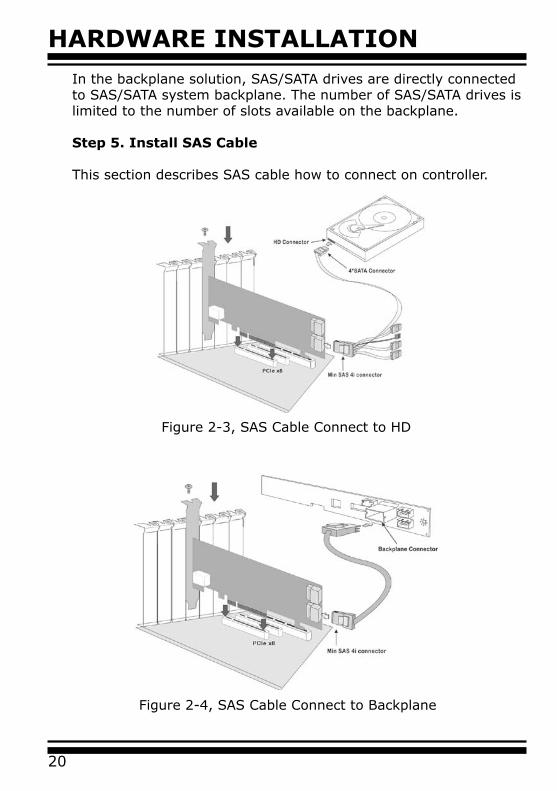
Figure 2-4, SAS Cable Connect to Backplane
Figure 2-3, SAS Cable Connect to HD
In the backplane solution, SAS/SATA drives are directly connected to SAS/SATA system backplane. The number of SAS/SATA drives is limited to the number of slots available on the backplane.
Step 5. Install SAS Cable
This section describes SAS cable how to connect on controller.
HARDWARE INSTALLATION
21
Step 6. Install the LED Cable (option)
The preferred I/O connector for server backplanes is the Min SAS 4i internal connector. This connector has eight signal pins to support four SAS/SATA drives and six pins for the SGPIO (Serial General Purpose Input/Output) side-band signals. The SGPIO bus is used for efficient LED management and for sensing drive Locate status. See SFF 8485 for the specification of the SGPIO bus. For backplane without SGPIO supporting, Please refer to Section 2.4 LED cables for Fault/Activity LED cable installation.
LED Management: The backplane may contain LEDs to indicate drive status. Light from the LEDs could be transmitted to the out-side of the server by using light pipes mounted on the SAS drive tray. A small microcontroller on the backplane, connected via the SGPIO bus to a SAS RAID controller, could control the LEDs. Activ-ity: blinking 5 times/second and Fault: solid illuminated
Drive Locate Circuitry: The location of a drive may be detected by sensing the voltage level of one of the pre-charge pins before and after a drive is installed.
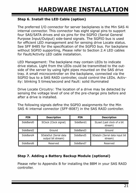
The following signals define the SGPIO assignments for the Min SAS 4i internal connector (SFF-8087) in the SAS RAID controller.
PIN Description PIN Description
SideBand0 SClock (Clock signal) SideBand1 SLoad (Last clock of a bit stream)
SideBand2 Ground SideBand3 Ground
SideBand4 SDataOut (Serial data output bit stream)
SideBand5 SDataIn (Serial data input bit stream)
SideBand6 Reserved SideBand7 Reserved
Step 7. Adding a Battery Backup Module (optional)
Please refer to Appendix B for installing the BBM in your SAS RAID controller.

HARDWARE INSTALLATION
22
Step 8. Re-check Fault LED Cable Connections (optional)
Be sure that the proper failed drive channel information is dis-played by the Fault LEDs. An improper connection will tell the user to ‘‘Hot Swap’’ the wrong drive. This can result in removing the wrong disk (one that is functioning properly) from the controller. This can result in failure and loss of system data.
Step 9. Power up the System
After check the installation, reinstall the computer cover, and reconnect the power cord cables. Turn on the power switch at the rear of the computer (if equipped) and then press the power but-ton at the front of the host computer.
Step 10. Configure Volume Set
The controller configures RAID functionality through the McBIOS RAID manager. Please refer to Chapter 3, McBIOS RAID Manager, for the detail. The RAID controller can also be configured through the McRAID storage manager with ArcHttp proxy server installed, LCD module (refer to LCD manual) or through on-board LAN port. For this option, please refer to Chapter 6, Web Browser-Based Configuration.
Step 11. Install the Controller Driver
For a new system: • Driver installation usually takes places as part of operating sys-tem installation. Please refer to Chapter 4 Diver Installation for the detailed installation procedure. In an existing system: • To install the controller driver into the existing operating system. For the detailed installation procedure, please refer to the Chapter 4, Driver Installation.
Note:
For lastest release versions of drivers, please download from http://www.areca.com.tw
HARDWARE INSTALLATION
23
Step 12. Install ArcHttp Proxy Server
The SAS RAID controller firmware has embedded the web-browser McRAID storage manager. ArcHttp proxy server will launch the web-browser McRAID storage manager. It provides all of the cre-ation, management and monitor SAS RAID controller status. Please refer to the Chapter 5 for the detail ArcHttp Proxy Server Installa-tion. For SNMP agent function, please refer to Appendix C.
Step 13. Determining the Boot Sequences
The SAS RAID controller is a bootable controller. If your system already contains a bootable device with an installed operating system, you can set up your system to boot a second operating system from the new controller. To add a second bootable control-ler, you may need to enter setup of motherboard BIOS and change the device boot sequence so that the SAS RAID controller heads the list. If the system BIOS setup does not allow this change, your system may not configurable to allow the SAS RAID controller to act as a second boot device.
2.4 SAS Cables
You can connect the end devices to each other through direct ca-bles or through the SAS expander/backplane connections. The SAS RAID controller supports daisy-chain expansion up to 8 enclosures. The following is an example of some internal SAS/SATA cables and an external SAS cable.
2.4.1 Internal Min SAS 4i to SATA Cable
The Min SAS 4i to SATA cables are used for connection between the SAS RAID controller internal connectors and connectors on the SAS/SATA disk drives or SAS/SATA connector backplane. The SAS controllers has 1-2 Min SAS 4i (SFF-8087) internal connec-tors, each of them can support up to four SAS/SATA drives. These adapters can be installed in a server RAID enclosure with standard SATA connectors backplane. The following diagram shows the picture of Min SAS 4i to 4 x SATA cables. Backplane

HARDWARE INSTALLATION
24
supports SGPIO header can leverage the SGPIO function on the SAS RAID controller through the sideband cable.
The sideband cable is reserved for the backplane with header on it.
Figure 2-5, Internal Min SAS 4i to 4x SATA Cable
2.4.2 Internal Min SAS 4i to 4xSFF-8482 Cable
These controllers can be installed in a server RAID enclosure with out a backplane. The kind of cable will attach directly to the SAS disk drives. The following diagram shows the picture of Min SAS 4i to 4xSFF-8482 cables.
Figure 2-6, Min SAS 4i to 4xSFF-8482 Cable
HARDWARE INSTALLATION
25
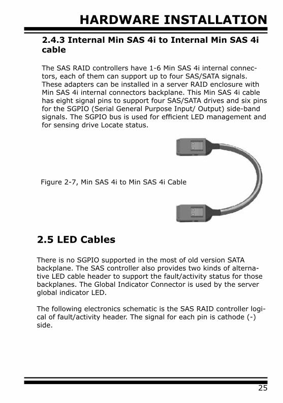
Figure 2-7, Min SAS 4i to Min SAS 4i Cable
2.4.3 Internal Min SAS 4i to Internal Min SAS 4i cable
The SAS RAID controllers have 1-6 Min SAS 4i internal connec-tors, each of them can support up to four SAS/SATA signals. These adapters can be installed in a server RAID enclosure with Min SAS 4i internal connectors backplane. This Min SAS 4i cable has eight signal pins to support four SAS/SATA drives and six pins for the SGPIO (Serial General Purpose Input/ Output) side-band signals. The SGPIO bus is used for efficient LED management and for sensing drive Locate status.
2.5 LED Cables
There is no SGPIO supported in the most of old version SATA backplane. The SAS controller also provides two kinds of alterna-tive LED cable header to support the fault/activity status for those backplanes. The Global Indicator Connector is used by the server global indicator LED.
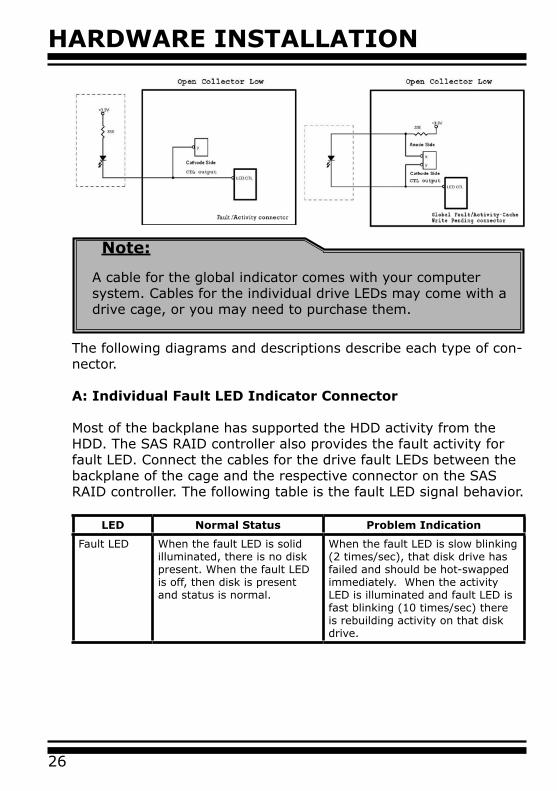
The following electronics schematic is the SAS RAID controller logi-cal of fault/activity header. The signal for each pin is cathode (-) side.
HARDWARE INSTALLATION
26
Note:
A cable for the global indicator comes with your computersystem. Cables for the individual drive LEDs may come with adrive cage, or you may need to purchase them.
The following diagrams and descriptions describe each type of con-nector.
A: Individual Fault LED Indicator Connector
Most of the backplane has supported the HDD activity from the HDD. The SAS RAID controller also provides the fault activity for fault LED. Connect the cables for the drive fault LEDs between the backplane of the cage and the respective connector on the SAS RAID controller. The following table is the fault LED signal behavior.
LED Normal Status Problem Indication
Fault LED When the fault LED is solid illuminated, there is no disk present. When the fault LED is off, then disk is present and status is normal.
When the fault LED is slow blinking (2 times/sec), that disk drive has failed and should be hot-swapped immediately. When the activity LED is illuminated and fault LED is fast blinking (10 times/sec) there is rebuilding activity on that disk drive.

HARDWARE INSTALLATION
27
B: I2C ConnectorYou can also connect the I2C interface to a proprietary SAS/SATA backplane enclosure. This can reduce the number of activity LED and/or fault LED cables. The I2C interface can also cascade to another SAS/SATA backplane enclosure for the additional channel status display.
Figure 2-8, ARC-1212/1222 Individual LED Indicators con-nector, for each channel drive.
Figure 2-15, Activity/Fault LED I2C connector connected between SAS RAID Controller & 4 SATA HDD backplane.
The following picture and table is the I2C signal name description for LCD & fault/activity LED.

HARDWARE INSTALLATION
28
C: Global Indicator Connector If the system will use only a single global activity/fault indicator, attach the LED to the two pins global activity and two pins global fault connector. The global fault pin pair connector is the overall fault signals. The global activity pin pair connector is the overall activity signals.
The following diagrams show the connector and pin locations.
2.6 Summary of the installation
The flow chart below describes the installation procedures for SAS RAID controllers. These procedures includes hardware installation, the creation and configuration of a RAID volume through the Mc-BIOS/McRAID, OS installation and installation of SAS RAID control-ler software. The software components configure and monitor the SAS RAID controllers as following table.
PIN Description PIN Description
1 Power (+5V) 2 GND
3 LCD Module Interrupt 4 Protect Key
5 LCD Module Serial Data 6 Fault/Activity Clock
7 Fault/Activity Serial Data 8 LCD Module Clock
Figure 2-9, ARC-1212/1222 Global Indicator Connector for Computer Case.
HARDWARE INSTALLATION
29
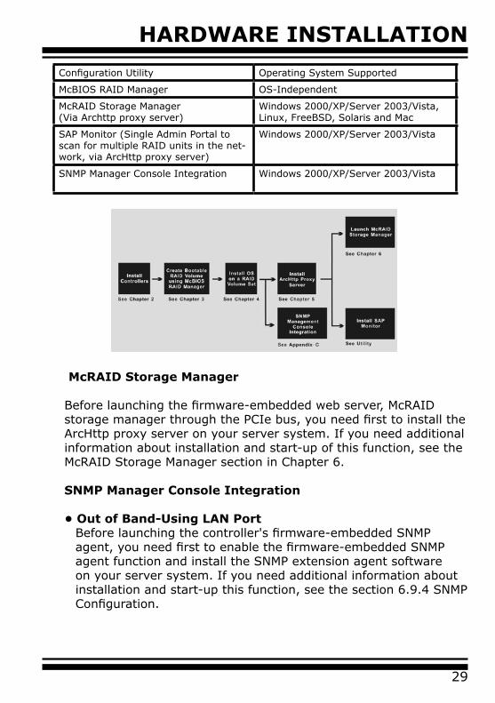
Configuration Utility Operating System Supported
McBIOS RAID Manager OS-Independent
McRAID Storage Manager(Via Archttp proxy server)
Windows 2000/XP/Server 2003/Vista, Linux, FreeBSD, Solaris and Mac
SAP Monitor (Single Admin Portal to scan for multiple RAID units in the net-work, via ArcHttp proxy server)
Windows 2000/XP/Server 2003/Vista
SNMP Manager Console Integration Windows 2000/XP/Server 2003/Vista
McRAID Storage Manager
Before launching the firmware-embedded web server, McRAID storage manager through the PCIe bus, you need first to install the ArcHttp proxy server on your server system. If you need additional information about installation and start-up of this function, see the McRAID Storage Manager section in Chapter 6.
SNMP Manager Console Integration
• Out of Band-Using LAN PortBefore launching the controller's firmware-embedded SNMP agent, you need first to enable the firmware-embedded SNMP agent function and install the SNMP extension agent software on your server system. If you need additional information about installation and start-up this function, see the section 6.9.4 SNMP Configuration.
HARDWARE INSTALLATION
30
• In-Band-Using PCIe BusBefore launching the SNMP agent in the sever, you need first to enable the firmware-embedded SNMP community configuration and install Areca SNMP extension agent in your server system. If you need additional information about installation and start-up the function, see the SNMP Operation & Installation section in the Appendix C.
Single Admin Portal (SAP) Monitor
This utility can scan for multiple RAID units on the network and monitor the controller set status. It also includes a Disk Stress Test (DST) utility to identify marginal spec disks before the RAID unit is put into a production environment.
For additional information, see the utility manual (SAP) in the soft-ware packaged CD or download it from the web site http://www.areca.com.tw

BIOS CONFIGURATION
31
3. McBIOS RAID ManagerThe system mainboard BIOS automatically configures the following SAS RAID controller parameters at power-up:
• I/O Port Address• Interrupt Channel (IRQ) • Adapter ROM Base Address
Use McBIOS RAID manager to further configure the SAS RAID control-ler to suit your server hardware and operating system.
3.1 Starting the McBIOS RAID Manager
This section explains how to use the McBIOS RAID manager to configure your RAID system. The McBIOS RAID manager is de-signed to be user-friendly. It is a menu-driven program, residing in the firmware, which allows you to scroll through various menus and sub-menus and select among the predetermined configuration options.
When starting a system with a SAS RAID controller installed, it will display the following message on the monitor during the start-up sequence (after the system BIOS startup screen but before the operating system boots):
The McBIOS RAID manager message remains on your screen for about nine seconds, giving you time to start the configuration menu by pressing Tab or F6. If you do not wish to enter configu-ration menu, press ESC to skip configuration immediately. When activated, the McBIOS RAID manager window appears showing a selection dialog box listing the SAS RAID controllers that are in-stalled in the system.The legend at the bottom of the screen shows you what keys are enabled for the windows.
Bus/Dev/Fun= 1/0/0, I/0-Port=28000000h, IRQ=9, BIOS=CB00 : 0hNo BIOS disk found. RAID controller BIOS not installed! Press <Tab/F6> to enter SETUP menu. 9 second(s) left <ESC to Skip>..
ARC-1212 PCIEx4 RAID Controller - DRAM: 256(MB) / #Channels: 16 BIOS: V1.17b / Date: 2006-8-07 - F/W: V1.42 / Date: 2007-3-1
BIOS CONFIGURATION
32
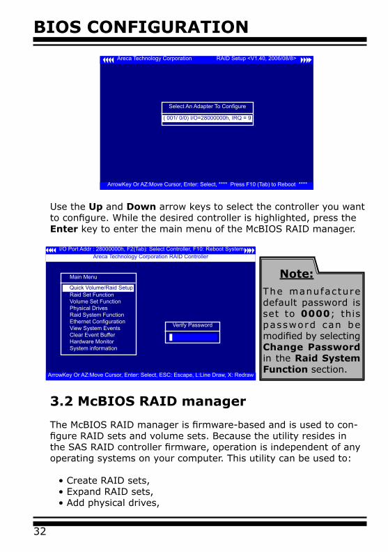
Areca Technology Corporation RAID Setup <V1.40, 2006/08/8>
ArrowKey Or AZ:Move Cursor, Enter: Select, **** Press F10 (Tab) to Reboot ****
Select An Adapter To Configure
( 001/ 0/0) I/O=28000000h, IRQ = 9
Use the Up and Down arrow keys to select the controller you want to configure. While the desired controller is highlighted, press the Enter key to enter the main menu of the McBIOS RAID manager.
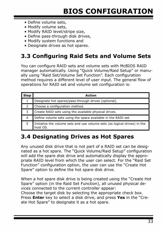
3.2 McBIOS RAID manager
The McBIOS RAID manager is firmware-based and is used to con-figure RAID sets and volume sets. Because the utility resides in the SAS RAID controller firmware, operation is independent of any operating systems on your computer. This utility can be used to:
• Create RAID sets,• Expand RAID sets,• Add physical drives,
I/O Port Addr : 28000000h, F2(Tab): Select Controller, F10: Reboot System
ArrowKey Or AZ:Move Cursor, Enter: Select, ESC: Escape, L:Line Draw, X: Redraw
Areca Technology Corporation RAID Controller
Main Menu
Raid Set FunctionVolume Set FunctionPhysical DrivesRaid System FunctionEthernet ConfigurationView System EventsClear Event BufferHardware MonitorSystem information
Quick Volume/Raid Setup
Verify Password
Note:
The manufacture default password is set to 0000; this password can be modified by selecting Change Password in the Raid System Function section.
BIOS CONFIGURATION
33
3.4 Designating Drives as Hot Spares
Any unused disk drive that is not part of a RAID set can be desig-nated as a hot spare. The “Quick Volume/Raid Setup” configuration will add the spare disk drive and automatically display the appro-priate RAID level from which the user can select. For the “Raid Set Function” configuration option, the user can use the “Create Hot Spare” option to define the hot spare disk drive.
When a hot spare disk drive is being created using the “Create Hot Spare” option (in the Raid Set Function), all unused physical de-vices connected to the current controller appear: Choose the target disk by selecting the appropriate check box.Press Enter key to select a disk drive, and press Yes in the “Cre-ate Hot Spare” to designate it as a hot spare.
• Define volume sets,• Modify volume sets,• Modify RAID level/stripe size,• Define pass-through disk drives,• Modify system functions and• Designate drives as hot spares.
3.3 Configuring Raid Sets and Volume Sets
You can configure RAID sets and volume sets with McBIOS RAID manager automatically. Using “Quick Volume/Raid Setup” or manu-ally using “Raid Set/Volume Set Function”. Each configuration method requires a different level of user input. The general flow of operations for RAID set and volume set configuration is:
Step Action
1 Designate hot spares/pass-through drives (optional).
2 Choose a configuration method.
3 Create RAID sets using the available physical drives.
4 Define volume sets using the space available in the RAID set.
5 Initialize the volume sets and use volume sets (as logical drives) in the host OS.
BIOS CONFIGURATION
34
3.5 Using Quick Volume /Raid Setup Con-figuration
“Quick Volume / Raid Setup configuration” collects all available drives and includes them in a RAID set. The RAID set you created is associated with exactly one volume set. You will only be able to modify the default RAID level, stripe size and capacity of the new volume set. Designating drives as hot spares is also possible in the “Raid Level” selection option. The volume set default settings will be:
Parameter Setting
Volume Name ARC-1212-VOL#00
SCSI Channel/SCSI ID/SCSI LUN 0/0/0
Cache Mode Write Back
Tag Queuing Yes
The default setting values can be changed after configuration is completed. Follow the steps below to create arrays using the “RAID Set / Volume Set” method:
Step Action
1 Choose “Quick Volume /Raid Setup” from the main menu. The available RAID levels with hot spare for the current volume set drive are displayed.
2 It is recommended that you use drives of the same capacity in a specific array. If you use drives with different capacities in an array, all drives in the RAID set will be set to the capacity of the smallest drive in the RAID set.The numbers of physical drives in a specific array determines which RAID levels that can be implemented in the array.RAID 0 requires 1 or more physical drives.RAID 1 requires at least 2 physical drives.RAID 10 requires at least 3 physical drives.RAID 3 requires at least 3 physical drives. RAID 5 requires at least 3 physical drives.RAID 3 +Spare requires at least 4 physical drives.RAID 5 + Spare requires at least 4 physical drives.RAID 6 requires at least 4 physical drives.RAID 6 + Spare requires at least 5 physical drives.Highlight the desired RAID level for the volume set and press the Enter key to confirm.
BIOS CONFIGURATION
35
3.6 Using RAID Set/Volume Set Function Method
In “Raid Set Function”, you can use the “Create Raid Set” function to generate a new RAID set. In “Volume Set Function”, you can use the “Create Volume Set” function to generate an associated volume set and configuration parameters.
If the current controller has unused physical devices connected, you can choose the “Create Hot Spare” option in the “Raid Set Function” to define a global hot spare. Select this method to con-figure new RAID sets and volume sets. The “Raid Set/Volume Set Function” configuration option allows you to associate volume sets with partial and full RAID sets.
3 The capacity for the current volume set is entered after highlighting the desired RAID level and pressing the Enter key.The capacity for the current volume set is displayed. Use the UP and DOWN arrow keys to set the capacity of the volume set and press the Enter key to confirm. The available stripe sizes for the current volume set are then displayed.
4 Use the UP and DOWN arrow keys to select the current volume set stripe size and press the Enter key to confirm. This parameter speci-fies the size of the stripes written to each disk in a RAID 0, 1, 10, 5 or 6 volume set. You can set the stripe size to 4 KB, 8 KB, 16 KB, 32 KB, 64 KB, or 128 KB. A larger stripe size provides better read performance, especially when the computer preforms mostly sequential reads. How-ever, if the computer preforms random read requests more often, choose a smaller stripe size.
5 When you are finished defining the volume set, press the Yes key to confirm the “Quick Volume And Raid Set Setup” function.
6 Foreground (Fast Completion) Press Enter key to define fast initialization or selected the Background (Instant Available) or No Init (To Rescue Vol-ume). In the “Background Initialization”, the initialization proceeds as a background task, the volume set is fully accessible for system reads and writes. The operating system can instantly access to the newly created arrays without requiring a reboot and waiting the initialization complete. In “Foreground Initialization”, the initialization proceeds must be com-pleted before the volume set ready for system accesses. In “No Init”, there is no initialization on this volume.
7 Initialize the volume set you have just configured
8 If you need to add additional volume set, using main menu “Create Vol-ume Set” function.
BIOS CONFIGURATION
36
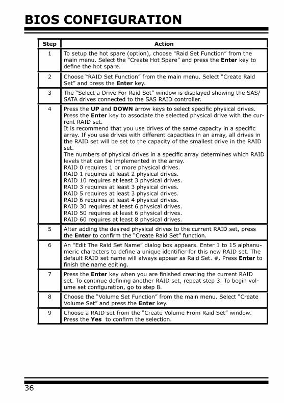
Step Action
1 To setup the hot spare (option), choose “Raid Set Function” from the main menu. Select the “Create Hot Spare” and press the Enter key to define the hot spare.
2 Choose “RAID Set Function” from the main menu. Select “Create Raid Set” and press the Enter key.
3 The “Select a Drive For Raid Set” window is displayed showing the SAS/SATA drives connected to the SAS RAID controller.
4 Press the UP and DOWN arrow keys to select specific physical drives. Press the Enter key to associate the selected physical drive with the cur-rent RAID set.It is recommend that you use drives of the same capacity in a specific array. If you use drives with different capacities in an array, all drives in the RAID set will be set to the capacity of the smallest drive in the RAID set.The numbers of physical drives in a specific array determines which RAID levels that can be implemented in the array.RAID 0 requires 1 or more physical drives.RAID 1 requires at least 2 physical drives.RAID 10 requires at least 3 physical drives.RAID 3 requires at least 3 physical drives. RAID 5 requires at least 3 physical drives.RAID 6 requires at least 4 physical drives.RAID 30 requires at least 6 physical drives.RAID 50 requires at least 6 physical drives.RAID 60 requires at least 8 physical drives.
5 After adding the desired physical drives to the current RAID set, press the Enter to confirm the “Create Raid Set” function.
6 An “Edit The Raid Set Name” dialog box appears. Enter 1 to 15 alphanu-meric characters to define a unique identifier for this new RAID set. The default RAID set name will always appear as Raid Set. #. Press Enter to finish the name editing.
7 Press the Enter key when you are finished creating the current RAID set. To continue defining another RAID set, repeat step 3. To begin vol-ume set configuration, go to step 8.
8 Choose the “Volume Set Function” from the main menu. Select “Create Volume Set” and press the Enter key.
9 Choose a RAID set from the “Create Volume From Raid Set” window. Press the Yes to confirm the selection.

BIOS CONFIGURATION
37
3.7 Main Menu
The main menu shows all functions that are available for executing actions, which is accomplished by clicking on the appropriate link.
Note:
The manufacture default password is set to 0000; this password can be modified by selecting “Change Password” in the “Raid System Function” section.
I/O Port Addr : 28000000h, F2(Tab): Select Controller, F10: Reboot System
ArrowKey Or AZ:Move Cursor, Enter: Select, ESC: Escape, L:Line Draw, X: Redraw
Areca Technology Corporation RAID Controller
Main Menu
Raid Set FunctionVolume Set FunctionPhysical DrivesRaid System FunctionEthernet ConfigurationView System EventsClear Event BufferHardware MonitorSystem information
Quick Volume/Raid Setup
Verify Password
10 Choosing Foreground (Fast Completion) Press Enter key to define fast initialization or selected the Background (Instant Available) or No Init (To Rescue Volume). In the “Background Initialization”, the initialization proceeds as a background task, the volume set is fully accessible for system reads and writes. The operating system can instantly access to the newly created arrays without requiring a reboot and waiting the initialization complete. In “Foreground Initialization”, the initialization proceeds must be completed before the volume set ready for system accesses. In “No Init”, there is no initialization on this volume.
11 If space remains in the RAID set, the next volume set can be configured. Repeat steps 8 to 10 to configure another volume set.

BIOS CONFIGURATION
38
Option Description
Quick Volume/Raid Setup Create a default configuration based on the number of physical disk installed
Raid Set Function Create a customized RAID set
Volume Set Function Create a customized volume set
Physical Drives View individual disk information
Raid System Function Setup the RAID system configuration
Ethernet Configuration Ethernet LAN setting
View System Events Record all system events in the buffer
Clear Event Buffer Clear all information in the event buffer
Hardware Monitor Show the hardware system environment status
System Information View the controller system information
This password option allows user to set or clear the RAID control-ler’s password protection feature. Once the password has been set, the user can only monitor and configure the RAID controller by pro-viding the correct password. The password is used to protect the internal RAID controller from unauthorized entry. The controller will prompt for the password only when entering the main menu from the initial screen. The RAID controller will automatically return to the initial screen when it does not receive any command in twenty seconds.
3.7.1 Quick Volume/RAID Setup
“Quick Volume/RAID Setup” is the fastest way to prepare a RAID set and volume set. It requires only a few keystrokes to com-plete. Although disk drives of different capacity may be used in the RAID Set, it will use the capacity of the smallest disk drive as the capacity of all disk drives in the RAID Set. The “Quick Vol-ume/RAID Setup” option creates a RAID set with the following properties:
1. All of the physical drives are contained in one RAID set.2. The RAID level, hot spare, capacity, and stripe size options are selected during the configuration process.3. When a single volume set is created, it can consume all or a portion of the available disk capacity in this RAID set.
BIOS CONFIGURATION
39
I/O Port Addr : 28000000h, F2(Tab): Select Controller, F10: Reboot System
ArrowKey Or AZ:Move Cursor, Enter: Select, ESC: Escape, L:Line Draw, X: Redraw
Areca Technology Corporation RAID Controller
Main Menu
Raid Set FunctionVolume Set FunctionPhysical DrivesRaid System FunctionEthernet ConfigurationView System EventsClear Event BufferHardware MonitorSystem information
Quick Volume/Raid Setup
Total 5 Drives
Raid 0Raid 1 + 0Raid 1 + 0 + SpareRaid 3Raid 5Raid 3 + SpareRaid 5 + SpareRaid 6 Raid 6 + Spare
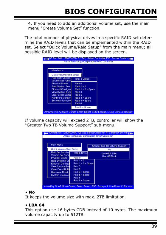
If volume capacity will exceed 2TB, controller will show the “Greater Two TB Volume Support” sub-menu.
• No It keeps the volume size with max. 2TB limitation.
• LBA 64 This option use 16 bytes CDB instead of 10 bytes. The maximum volume capacity up to 512TB.
I/O Port Addr : 28000000h, F2(Tab): Select Controller, F10: Reboot System
ArrowKey Or AZ:Move Cursor, Enter: Select, ESC: Escape, L:Line Draw, X: Redraw
Areca Technology Corporation RAID Controller
Main Menu
Raid Set FunctionVolume Set FunctionPhysical DrivesRaid System FunctionEthernet ConfigurationView System EventsClear Event BufferHardware MonitorSystem information
Quick Volume/Raid SetupTotal 5 Drives
Raid 0Raid 1 + 0Raid 1 + 0 + SpareRaid 3Raid 5Raid 3 + SpareRaid 5 + SpareRaid 6Raid 6 + Spare
Raid 0
Greater Two TB Volume Support
No Use 64bit LBA Use 4K Block
No
4. If you need to add an additional volume set, use the main menu “Create Volume Set” function.
The total number of physical drives in a specific RAID set deter-mine the RAID levels that can be implemented within the RAID set. Select “Quick Volume/Raid Setup” from the main menu; all possible RAID level will be displayed on the screen.
BIOS CONFIGURATION
40
This option works on different OS which supports 16 bytes CDB. Such as:Windows 2003 with SP1Linux kernel 2.6.x or latter
For more details, please download pdf file from ftp://ftp.areca.com.tw/RaidCards/Documents/Manual_Spec/Over2TB_050721.zip
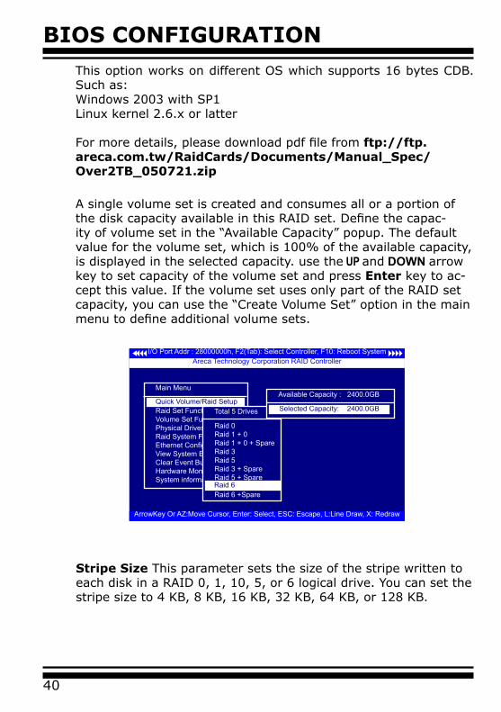
A single volume set is created and consumes all or a portion of the disk capacity available in this RAID set. Define the capac-ity of volume set in the “Available Capacity” popup. The default value for the volume set, which is 100% of the available capacity, is displayed in the selected capacity. use the UP and DOWN arrow key to set capacity of the volume set and press Enter key to ac-cept this value. If the volume set uses only part of the RAID set capacity, you can use the “Create Volume Set” option in the main menu to define additional volume sets.
I/O Port Addr : 28000000h, F2(Tab): Select Controller, F10: Reboot System
ArrowKey Or AZ:Move Cursor, Enter: Select, ESC: Escape, L:Line Draw, X: Redraw
Areca Technology Corporation RAID Controller
Main Menu
Raid Set FunctionVolume Set FunctionPhysical DrivesRaid System FunctionEthernet ConfigurationView System EventsClear Event BufferHardware MonitorSystem information
Quick Volume/Raid SetupTotal 5 Drives
Raid 0Raid 1 + 0Raid 1 + 0 + SpareRaid 3Raid 5Raid 3 + SpareRaid 5 + SpareRaid 6 Raid 6 +SpareRaid 6
Available Capacity : 2400.0GB
Selected Capacity: 2400.0GB
Stripe Size This parameter sets the size of the stripe written to each disk in a RAID 0, 1, 10, 5, or 6 logical drive. You can set the stripe size to 4 KB, 8 KB, 16 KB, 32 KB, 64 KB, or 128 KB.
BIOS CONFIGURATION
41
I/O Port Addr : 28000000h, F2(Tab): Select Controller, F10: Reboot System
ArrowKey Or AZ:Move Cursor, Enter: Select, ESC: Escape, L:Line Draw, X: Redraw
Areca Technology Corporation RAID Controller
Main Menu
Raid Set FunctionVolume Set FunctionPhysical DrivesRaid System FunctionEthernet ConfigurationView System EventsClear Event BufferHardware MonitorSystem information
Quick Volume/Raid SetupTotal 5 Drives
Raid 0Raid 1 + 0Raid 1 + 0 + SpareRaid 3Raid 5Raid 3 + SpareRaid 5 + SpareRaid 6 Raid 6 +SpareRaid 6
Available Capacity : 2400.0GB
Selected Capacity: 2400.0GB
Select Strip Size
4K 8K 16K 32K
128K 64K
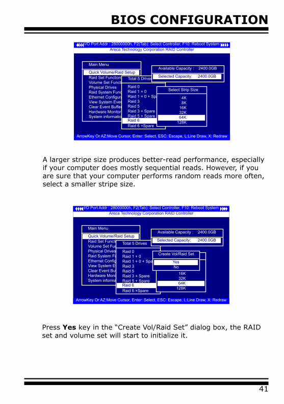
A larger stripe size produces better-read performance, especially if your computer does mostly sequential reads. However, if you are sure that your computer performs random reads more often, select a smaller stripe size.
Press Yes key in the “Create Vol/Raid Set” dialog box, the RAID set and volume set will start to initialize it.
I/O Port Addr : 28000000h, F2(Tab): Select Controller, F10: Reboot System
ArrowKey Or AZ:Move Cursor, Enter: Select, ESC: Escape, L:Line Draw, X: Redraw
Areca Technology Corporation RAID Controller
Main Menu
Raid Set FunctionVolume Set FunctionPhysical DrivesRaid System FunctionEthernet ConfigurationView System EventsClear Event BufferHardware MonitorSystem information
Quick Volume/Raid Setup
Total 5 Drives
Raid 0Raid 1 + 0Raid 1 + 0 + SpareRaid 3Raid 5Raid 3 + SpareRaid 5 + SpareRaid 6 Raid 6 +SpareRaid 6
Available Capacity : 2400.0GB
Selected Capacity: 2400.0GB
Select Strip Size
4K 8K 16K 32K
128K 64K
Create Vol/Raid Set
NoYes
BIOS CONFIGURATION
42
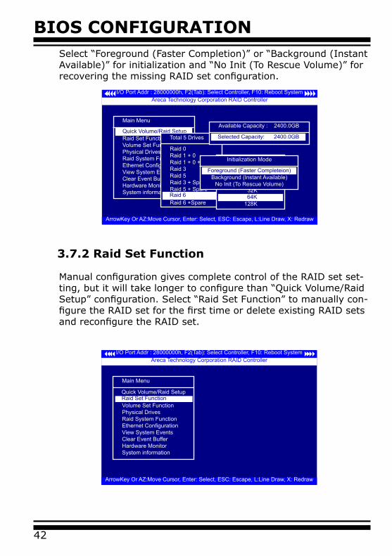
3.7.2 Raid Set Function
Manual configuration gives complete control of the RAID set set-ting, but it will take longer to configure than “Quick Volume/Raid Setup” configuration. Select “Raid Set Function” to manually con-figure the RAID set for the first time or delete existing RAID sets and reconfigure the RAID set.
I/O Port Addr : 28000000h, F2(Tab): Select Controller, F10: Reboot System
ArrowKey Or AZ:Move Cursor, Enter: Select, ESC: Escape, L:Line Draw, X: Redraw
Areca Technology Corporation RAID Controller
Main Menu
Raid Set FunctionVolume Set FunctionPhysical DrivesRaid System FunctionEthernet ConfigurationView System EventsClear Event BufferHardware MonitorSystem information
Quick Volume/Raid SetupTotal 5 Drives
Raid 0Raid 1 + 0Raid 1 + 0 + SpareRaid 3Raid 5Raid 3 + SpareRaid 5 + SpareRaid 6 Raid 6 +SpareRaid 6
Available Capacity : 2400.0GB
Selected Capacity: 2400.0GB
Select Strip Size
4K 8K 16K 32K
128K 64K
Initialization Mode
Background (Instant Available)No Init (To Rescue Volume)
Foreground (Faster Completeion)
Select “Foreground (Faster Completion)” or “Background (Instant Available)” for initialization and “No Init (To Rescue Volume)” for recovering the missing RAID set configuration.
I/O Port Addr : 28000000h, F2(Tab): Select Controller, F10: Reboot System
ArrowKey Or AZ:Move Cursor, Enter: Select, ESC: Escape, L:Line Draw, X: Redraw
Areca Technology Corporation RAID Controller
Main Menu
Quick Volume/Raid SetupRaid Set FunctionVolume Set FunctionPhysical DrivesRaid System FunctionEthernet ConfigurationView System EventsClear Event BufferHardware MonitorSystem information
Raid Set Function
BIOS CONFIGURATION
43
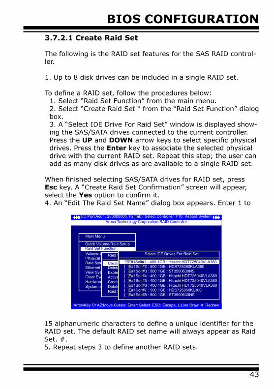
3.7.2.1 Create Raid Set
The following is the RAID set features for the SAS RAID control-ler.
1. Up to 8 disk drives can be included in a single RAID set.
To define a RAID set, follow the procedures below:1. Select “Raid Set Function” from the main menu.2. Select “Create Raid Set “ from the “Raid Set Function” dialog box.3. A “Select IDE Drive For Raid Set” window is displayed show-ing the SAS/SATA drives connected to the current controller. Press the UP and DOWN arrow keys to select specific physical drives. Press the Enter key to associate the selected physical drive with the current RAID set. Repeat this step; the user can add as many disk drives as are available to a single RAID set.
When finished selecting SAS/SATA drives for RAID set, press Esc key. A “Create Raid Set Confirmation” screen will appear, select the Yes option to confirm it. 4. An “Edit The Raid Set Name” dialog box appears. Enter 1 to
I/O Port Addr : 28000000h, F2(Tab): Select Controller, F10: Reboot System
ArrowKey Or AZ:Move Cursor, Enter: Select, ESC: Escape, L:Line Draw, X: Redraw
Areca Technology Corporation RAID Controller
Main Menu
Quick Volume/Raid SetupRaid Set FunctionVolume Set FunctionPhysical DrivesRaid System FunctionEthernet ConfigurationView System EventsClear Event BufferHardware MonitorSystem information
Raid Set Function
Raid Set Function
Delete Raid SetExpand Raid SetActivate Raid SetCreate Hot SpareDelete Hot SpareRaid Set Information
Create Raid Set
Select IDE Drives For Raid Set
[ ]E#1Solt#2 : 500.1GB : HDS725050KLA360[ ]E#1Solt#3 : 500.1GB : ST3500630NS[ ]E#1Solt#4 : 400.1GB : Hitachi HDT725040VLA360[ ]E#1Solt#5 : 400.1GB : Hitachi HDT725040VLA360[ ]E#1Solt#6 : 400.1GB : Hitachi HDT725040VLA360[ ]E#1Solt#7 : 500.1GB : HDS725050KL360[ ]E#1Solt#8 : 500.1GB : ST3500630NS
[*]E#1Solt#1 : 400.1GB : Hitachi HDT725040VLA360
15 alphanumeric characters to define a unique identifier for the RAID set. The default RAID set name will always appear as Raid Set. #.5. Repeat steps 3 to define another RAID sets.
BIOS CONFIGURATION
44
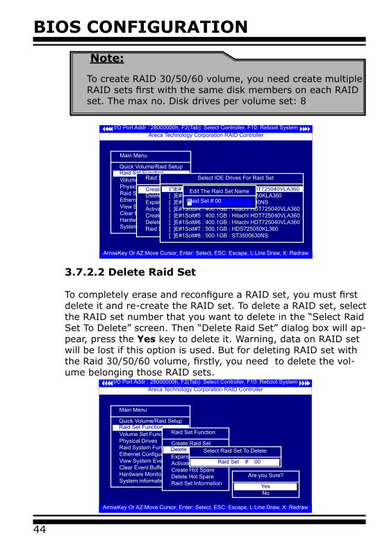
3.7.2.2 Delete Raid Set
To completely erase and reconfigure a RAID set, you must first delete it and re-create the RAID set. To delete a RAID set, select the RAID set number that you want to delete in the “Select Raid Set To Delete” screen. Then “Delete Raid Set” dialog box will ap-pear, press the Yes key to delete it. Warning, data on RAID set will be lost if this option is used. But for deleting RAID set with the Raid 30/50/60 volume, firstly, you need to delete the vol-ume belonging those RAID sets.
I/O Port Addr : 28000000h, F2(Tab): Select Controller, F10: Reboot System
ArrowKey Or AZ:Move Cursor, Enter: Select, ESC: Escape, L:Line Draw, X: Redraw
Areca Technology Corporation RAID Controller
Main Menu
Quick Volume/Raid SetupRaid Set FunctionVolume Set FunctionPhysical DrivesRaid System FunctionEthernet ConfigurationView System EventsClear Event BufferHardware MonitorSystem information
Raid Set FunctionRaid Set Function
Create Raid Set
Expand Raid SetActivate Raid SetCreate Hot SpareDelete Hot SpareRaid Set Information
Delete Raid SetSelect Raid Set To Delete
Raid Set # 00
Are you Sure?
NoYes
I/O Port Addr : 28000000h, F2(Tab): Select Controller, F10: Reboot System
ArrowKey Or AZ:Move Cursor, Enter: Select, ESC: Escape, L:Line Draw, X: Redraw
Areca Technology Corporation RAID Controller
Main Menu
Quick Volume/Raid SetupRaid Set FunctionVolume Set FunctionPhysical DrivesRaid System FunctionEthernet ConfigurationView System EventsClear Event BufferHardware MonitorSystem information
Raid Set FunctionRaid Set Function
Delete Raid SetExpand Raid SetActivate Raid SetCreate Hot SpareDelete Hot SpareRaid Set Information
Create Raid Set
Select IDE Drives For Raid Set
[ ]E#1Solt#2 : 500.1GB : HDS725050KLA360[ ]E#1Solt#3 : 500.1GB : ST3500630NS[ ]E#1Solt#4 : 400.1GB : Hitachi HDT725040VLA360[ ]E#1Solt#5 : 400.1GB : Hitachi HDT725040VLA360[ ]E#1Solt#6 : 400.1GB : Hitachi HDT725040VLA360[ ]E#1Solt#7 : 500.1GB : HDS725050KL360[ ]E#1Solt#8 : 500.1GB : ST3500630NS
[*]E#1Solt#1 : 400.1GB : Hitachi HDT725040VLA360Edit The Raid Set Name
aid Set # 00R
Note:
To create RAID 30/50/60 volume, you need create multiple RAID sets first with the same disk members on each RAID set. The max no. Disk drives per volume set: 8

BIOS CONFIGURATION
45
3.7.2.3 Expand Raid Set
Instead of deleting a RAID set and recreating it with additional disk drives, the “Expand Raid Set” function allows the users to add disk drives to the RAID set that have already been created.To expand a RAID set:Select the “Expand Raid Set” option. If there is an available disk, then the “Select SATA Drives For Raid Set Expansion” screen appears.Select the target RAID set by clicking on the appropriate radio button. Select the target disk by clicking on the appropriate check box.Press the Yes key to start the expansion on the RAID set.The new additional capacity can be utilized by one or more volume sets. The volume sets associated with this RAID set appear for you to have chance to modify RAID level or stripe size. Follow the instruction presented in the “Modify Volume Set ” to modify the volume sets; operation system specific utilities may be required to expand operating system partitions.
Note:
1. Once the “Expand Raid Set” process has started, user can not stop it. The process must be completed.2. If a disk drive fails during raid set expansion and a hot spare is available, an auto rebuild operation will occur after the RAID set expansion completes.3. RAID 30/50/60 doesn't support the "Expand Raid Set".
I/O Port Addr : 28000000h, F2(Tab): Select Controller, F10: Reboot System
ArrowKey Or AZ:Move Cursor, Enter: Select, ESC: Escape, L:Line Draw, X: Redraw
Areca Technology Corporation RAID Controller
Main Menu
Quick Volume/Raid SetupRaid Set FunctionVolume Set FunctionPhysical DrivesRaid System FunctionEthernet ConfigurationView System EventsClear Event BufferHardware MonitorSystem information
Raid Set FunctionRaid Set Function
Create Raid Set Delete Raid SetExpand Raid SetActivate Raid SetCreate Hot SpareDelete Hot SpareRaid Set Information
Expand Raid Set
Select IDE Drives For Raid Set Expansion
[*]E#1Solt#2 : 500.1GB : HDS725050KLA360[ ]E#1Solt#3 : 500.1GB : ST3500630NS[ ]E#1Solt#4 : 400.1GB : Hitachi HDT725040VLA360[ ]E#1Solt#5 : 400.1GB : Hitachi HDT725040VLA360[ ]E#1Solt#6 : 400.1GB : Hitachi HDT725040VLA360[ ]E#1Solt#7 : 500.1GB : HDS725050KL360[ ]E#1Solt#8 : 500.1GB : ST3500630NS
Are you Sure?
NoYes
BIOS CONFIGURATION
46
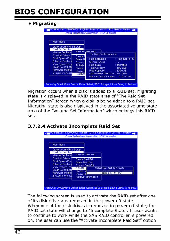
• Migrating
Migration occurs when a disk is added to a RAID set. Migrating state is displayed in the RAID state area of “The Raid Set Information” screen when a disk is being added to a RAID set. Migrating state is also displayed in the associated volume state area of the “Volume Set Information” which belongs this RAID set.
3.7.2.4 Activate Incomplete Raid SetI/O Port Addr : 28000000h, F2(Tab): Select Controller, F10: Reboot System
ArrowKey Or AZ:Move Cursor, Enter: Select, ESC: Escape, L:Line Draw, X: Redraw
Areca Technology Corporation RAID Controller
Main Menu
Quick Volume/Raid SetupRaid Set FunctionVolume Set FunctionPhysical DrivesRaid System FunctionEthernet ConfigurationView System EventsClear Event BufferHardware MonitorSystem information
Raid Set FunctionRaid Set Function
Create Raid Set Delete Raid SetExpand Raid SetActivate Raid SetCreate Hot SpareDelete Hot SpareRaid Set Information
Activate Raid Set Select Raid Set To Activate
Raid Set # 00
I/O Port Addr : 28000000h, F2(Tab): Select Controller, F10: Reboot System
ArrowKey Or AZ:Move Cursor, Enter: Select, ESC: Escape, L:Line Draw, X: Redraw
Areca Technology Corporation RAID Controller
Main Menu
Quick Volume/Raid SetupRaid Set FunctionVolume Set FunctionPhysical DrivesRaid System FunctionEthernet ConfigurationView System EventsClear Event BufferHardware MonitorSystem information
Raid Set FunctionRaid Set Function
Create Raid Set Delete Raid SetExpand Raid SetActivate Raid SetCreate Hot SpareDelete Hot SpareRaid Set InformationRaid Set Iformation
The Raid Set Information
Raid Set Name : Raid Set # 00Member Disks : 2Raid State : MigratingTotal Capacity : 800.0GBFree Capacity : 800.0GBMin Member Disk Size : 400.0GBMember Disk Channels : .E1S1.E1S2.
The following screen is used to activate the RAID set after one of its disk drive was removed in the power off state.When one of the disk drives is removed in power off state, the RAID set state will change to “Incomplete State”. If user wants to continue to work while the SAS RAID controller is powered on, the user can use the “Activate Incomplete Raid Set” option
BIOS CONFIGURATION
47
to active the RAID set. After user selects this function, the RAID state will change to “Degraded Mode” and start to work.
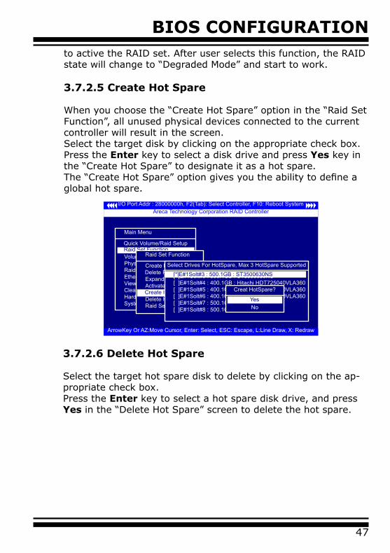
3.7.2.5 Create Hot Spare
When you choose the “Create Hot Spare” option in the “Raid Set Function”, all unused physical devices connected to the current controller will result in the screen. Select the target disk by clicking on the appropriate check box.Press the Enter key to select a disk drive and press Yes key in the “Create Hot Spare” to designate it as a hot spare.The “Create Hot Spare” option gives you the ability to define a global hot spare.
I/O Port Addr : 28000000h, F2(Tab): Select Controller, F10: Reboot System
ArrowKey Or AZ:Move Cursor, Enter: Select, ESC: Escape, L:Line Draw, X: Redraw
Areca Technology Corporation RAID Controller
Main Menu
Quick Volume/Raid SetupRaid Set FunctionVolume Set FunctionPhysical DrivesRaid System FunctionEthernet ConfigurationView System EventsClear Event BufferHardware MonitorSystem information
Raid Set FunctionRaid Set Function
Create Raid Set Delete Raid SetExpand Raid SetActivate Raid SetCreate Hot SpareDelete Hot SpareRaid Set Information
Create Hot Spare
Select Drives For HotSpare, Max 3 HotSpare Supported
[ ]E#1Solt#3 : 500.1GB : ST3500630NS[ ]E#1Solt#4 : 400.1GB : Hitachi HDT725040VLA360[ ]E#1Solt#5 : 400.1GB : Hitachi HDT725040VLA360[ ]E#1Solt#6 : 400.1GB : Hitachi HDT725040VLA360[ ]E#1Solt#7 : 500.1GB : HDS725050KL360[ ]E#1Solt#8 : 500.1GB : ST3500630NS
[*]E#1Solt#3 : 500.1GB : ST3500630NS
Creat HotSpare?
NoYes
3.7.2.6 Delete Hot Spare
Select the target hot spare disk to delete by clicking on the ap-propriate check box.Press the Enter key to select a hot spare disk drive, and press Yes in the “Delete Hot Spare” screen to delete the hot spare.
BIOS CONFIGURATION
48
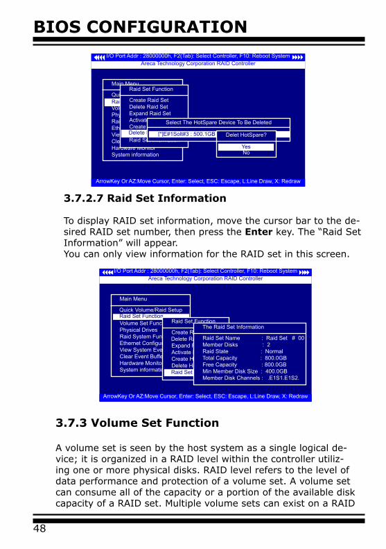
3.7.3 Volume Set Function
A volume set is seen by the host system as a single logical de-vice; it is organized in a RAID level within the controller utiliz-ing one or more physical disks. RAID level refers to the level of data performance and protection of a volume set. A volume set can consume all of the capacity or a portion of the available disk capacity of a RAID set. Multiple volume sets can exist on a RAID
I/O Port Addr : 28000000h, F2(Tab): Select Controller, F10: Reboot System
ArrowKey Or AZ:Move Cursor, Enter: Select, ESC: Escape, L:Line Draw, X: Redraw
Areca Technology Corporation RAID Controller
Main Menu
Quick Volume/Raid SetupRaid Set FunctionVolume Set FunctionPhysical DrivesRaid System FunctionEthernet ConfigurationView System EventsClear Event BufferHardware MonitorSystem information
Raid Set FunctionRaid Set Function
Create Raid Set Delete Raid SetExpand Raid SetActivate Raid SetCreate Hot SpareDelete Hot SpareRaid Set InformationRaid Set Iformation
The Raid Set Information
Raid Set Name : Raid Set # 00Member Disks : 2Raid State : NormalTotal Capacity : 800.0GBFree Capacity : 800.0GBMin Member Disk Size : 400.0GBMember Disk Channels : .E1S1.E1S2.
I/O Port Addr : 28000000h, F2(Tab): Select Controller, F10: Reboot System
ArrowKey Or AZ:Move Cursor, Enter: Select, ESC: Escape, L:Line Draw, X: Redraw
Areca Technology Corporation RAID Controller
Delete Raid Set
Main Menu
Quick Volume/Raid Setup
Volume Set FunctionPhysical DrivesRaid System FunctionEthernet ConfigurationView System EventsClear Event BufferHardware MonitorSystem information
Raid Set Function
Raid Set Function
Create Raid SetDelete Raid SetExpand Raid SetActivate Raid SetCreate Hot SpareDelete Hot SpareRaid Set InformationDelete Hot Spare
Select The HotSpare Device To Be Deleted
[ ]E#1Solt#3 : 500.1GB : ST3500630NS[*]E#1Solt#3 : 500.1GB : ST3500630NSDelet HotSpare?
NoYes
3.7.2.7 Raid Set Information
To display RAID set information, move the cursor bar to the de-sired RAID set number, then press the Enter key. The “Raid Set Information” will appear. You can only view information for the RAID set in this screen.
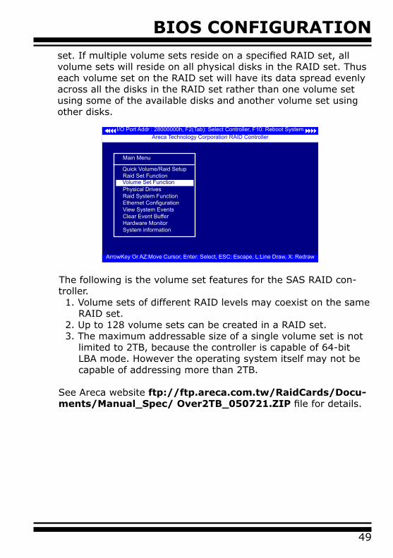
BIOS CONFIGURATION
49
set. If multiple volume sets reside on a specified RAID set, all volume sets will reside on all physical disks in the RAID set. Thus each volume set on the RAID set will have its data spread evenly across all the disks in the RAID set rather than one volume set using some of the available disks and another volume set using other disks.
I/O Port Addr : 28000000h, F2(Tab): Select Controller, F10: Reboot System
ArrowKey Or AZ:Move Cursor, Enter: Select, ESC: Escape, L:Line Draw, X: Redraw
Areca Technology Corporation RAID Controller
Main Menu
Quick Volume/Raid SetupRaid Set FunctionVolume Set FunctionPhysical DrivesRaid System FunctionEthernet ConfigurationView System EventsClear Event BufferHardware MonitorSystem information
Volume Set Function
The following is the volume set features for the SAS RAID con-troller.
1. Volume sets of different RAID levels may coexist on the same RAID set.2. Up to 128 volume sets can be created in a RAID set.3. The maximum addressable size of a single volume set is not limited to 2TB, because the controller is capable of 64-bit LBA mode. However the operating system itself may not be capable of addressing more than 2TB.
See Areca website ftp://ftp.areca.com.tw/RaidCards/Docu-ments/Manual_Spec/ Over2TB_050721.ZIP file for details.
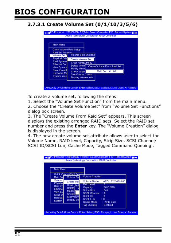
BIOS CONFIGURATION
50
3.7.3.1 Create Volume Set (0/1/10/3/5/6)
I/O Port Addr : 28000000h, F2(Tab): Select Controller, F10: Reboot System
ArrowKey Or AZ:Move Cursor, Enter: Select, ESC: Escape, L:Line Draw, X: Redraw
Areca Technology Corporation RAID Controller
Main Menu
Quick Volume/Raid SetupRaid Set FunctionVolume Set FunctionPhysical DrivesRaid System FunctionEthernet ConfigurationView System EventsClear Event BufferHardware MonitorSystem information
Volume Set FunctionVolume Set Functions
Creat Volume SetCreat Raid30/50/60Delete Volume SetModify Volume SetCheck Volume SetStopVolume CheckDisplay Volume Info.
Create Volume Set
Create Volume From Raid Set
Raid Set # 00
I/O Port Addr : 28000000h, F2(Tab): Select Controller, F10: Reboot System
ArrowKey Or AZ:Move Cursor, Enter: Select, ESC: Escape, L:Line Draw, X: Redraw
Areca Technology Corporation RAID Controller
Main Menu
Quick Volume/Raid SetupRaid Set FunctionVolume Set FunctionPhysical DrivesRaid System FunctionEthernet ConfigurationView System EventsClear Event BufferHardware MonitorSystem information
Volume Set FunctionVolume Set Functions
Creat Volume SetCreat Raid30/50/60Delete Volume SetModify Volume SetCheck Volume SetStopVolume CheckDisplay Volume Info.
Create Volume Set
Create Volume From Raid Set
Raid Set # 00
Volume Creation
Raid Level : 5Capacity : 2400.0GBStripe Size : 64KSCSI Channel : 0SCSI ID : 0SCSI LUN : 0Cache Mode : Write BackTag Queuing : Enabled
Volume Name : ARC-1212-VOL# 00
To create a volume set, following the steps:1. Select the “Volume Set Function” from the main menu.2. Choose the “Create Volume Set” from “Volume Set Functions” dialog box screen.3. The “Create Volume From Raid Set” appears. This screen displays the existing arranged RAID sets. Select the RAID set number and press the Enter key. The “Volume Creation” dialog is displayed in the screen. 4. The new create volume set attribute allows user to select the Volume Name, RAID level, Capacity, Strip Size, SCSI Channel/SCSI ID/SCSI Lun, Cache Mode, Tagged Command Queuing .
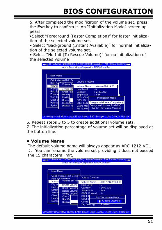
BIOS CONFIGURATION
51
5. After completed the modification of the volume set, press the Esc key to confirm it. An “Initialization Mode” screen ap-pears. •Select “Foreground (Faster Completion)” for faster initializa-tion of the selected volume set.• Select “Background (Instant Available)” for normal initializa-tion of the selected volume set.• Select “No Init (To Rescue Volume)” for no initialization of the selected volume
I/O Port Addr : 28000000h, F2(Tab): Select Controller, F10: Reboot System
ArrowKey Or AZ:Move Cursor, Enter: Select, ESC: Escape, L:Line Draw, X: Redraw
Areca Technology Corporation RAID Controller
Main Menu
Quick Volume/Raid SetupRaid Set FunctionVolume Set FunctionPhysical DrivesRaid System FunctionEthernet ConfigurationView System EventsClear Event BufferHardware MonitorSystem information
Volume Set FunctionVolume Set Functions
Creat Volume SetCreat Raid30/50/60Delete Volume SetModify Volume SetCheck Volume SetStopVolume CheckDisplay Volume Info.
Create Volume Set
Create Volume From Raid Set
Raid Set # 00
Volume Creation
Raid Level : 5Capacity : 2400.0GBStripe Size : 64KSCSI Channel : 0SCSI ID : 0SCSI LUN : 0Cache Mode : Write BackTag Queuing : Enabled
Volume Name : Volume Set # 00
Initialization Mode
Background (Instant Available)No Init (To Rescue Volume)
Foreground (Faster Completion)
6. Repeat steps 3 to 5 to create additional volume sets.7. The initialization percentage of volume set will be displayed at the button line.
• Volume NameThe default volume name will always appear as ARC-1212-VOL #. You can rename the volume set providing it does not exceed the 15 characters limit.
I/O Port Addr : 28000000h, F2(Tab): Select Controller, F10: Reboot System
ArrowKey Or AZ:Move Cursor, Enter: Select, ESC: Escape, L:Line Draw, X: Redraw
Areca Technology Corporation RAID Controller
Main Menu
Quick Volume/Raid SetupRaid Set FunctionVolume Set FunctionPhysical DrivesRaid System FunctionEthernet ConfigurationView System EventsClear Event BufferHardware MonitorSystem information
Volume Set FunctionVolume Set Functions
Creat Volume SetCreat Raid30/50/60Delete Volume SetModify Volume SetCheck Volume SetStopVolume CheckDisplay Volume Info.
Create Volume Set
Create Volume From Raid Set
Raid Set # 00
Volume Creation
Raid Level : 5Capacity : 2400.0GBStripe Size : 64KSCSI Channel : 0SCSI ID : 0SCSI LUN : 0Cache Mode : Write BackTag Queuing : Enabled
Volume Name : ARC-1212-VOL# 00
Edit The Volume NameRC-1680-VOL# 00 A
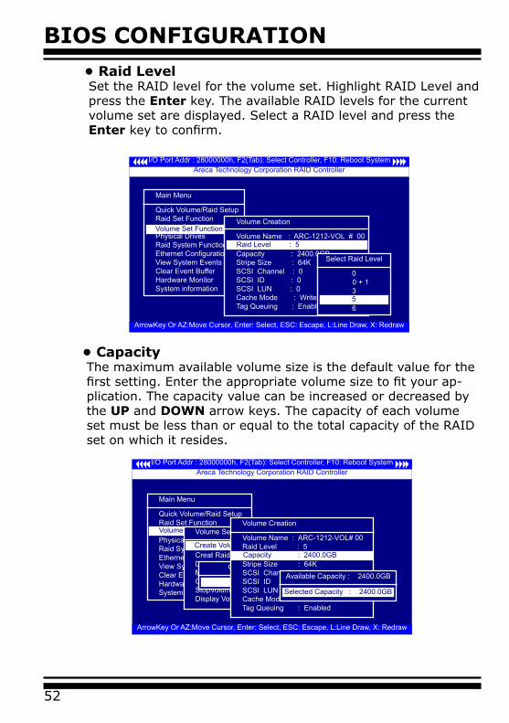
BIOS CONFIGURATION
52
• Raid LevelSet the RAID level for the volume set. Highlight RAID Level and press the Enter key. The available RAID levels for the current volume set are displayed. Select a RAID level and press the Enter key to confirm.
I/O Port Addr : 28000000h, F2(Tab): Select Controller, F10: Reboot System
ArrowKey Or AZ:Move Cursor, Enter: Select, ESC: Escape, L:Line Draw, X: Redraw
Areca Technology Corporation RAID Controller
Main Menu
Quick Volume/Raid SetupRaid Set FunctionVolume Set FunctionPhysical DrivesRaid System FunctionEthernet ConfigurationView System EventsClear Event BufferHardware MonitorSystem information
Volume Set FunctionVolume Creation
Volume Name : ARC-1212-VOL # 00Raid Level : 5Capacity : 2400.0GBStripe Size : 64KSCSI Channel : 0SCSI ID : 0SCSI LUN : 0Cache Mode : Write BackTag Queuing : Enabled
Raid Level : 5
Select Raid Level
0 0 + 1
3
65
• CapacityThe maximum available volume size is the default value for the first setting. Enter the appropriate volume size to fit your ap-plication. The capacity value can be increased or decreased by the UP and DOWN arrow keys. The capacity of each volume set must be less than or equal to the total capacity of the RAID set on which it resides.
I/O Port Addr : 28000000h, F2(Tab): Select Controller, F10: Reboot System
ArrowKey Or AZ:Move Cursor, Enter: Select, ESC: Escape, L:Line Draw, X: Redraw
Areca Technology Corporation RAID Controller
Main Menu
Quick Volume/Raid SetupRaid Set FunctionVolume Set FunctionPhysical DrivesRaid System FunctionEthernet ConfigurationView System EventsClear Event BufferHardware MonitorSystem information
Volume Set FunctionVolume Set Functions
Creat Volume SetCreat Raid30/50/60Delete Volume SetModify Volume SetCheck Volume SetStopVolume CheckDisplay Volume Info.
Create Volume Set
Create Volume From Raid Set
Raid Set # 00
Volume Creation
Volume Name : ARC-1212-VOL# 00 Raid Level : 5Capacity : 160.1GBStripe Size : 64KSCSI Channel : 0SCSI ID : 0SCSI LUN : 0Cache Mode : Write BackTag Queuing : Enabled
Capacity : 2400.0GB
Available Capacity : 2400.0GB
Selected Capacity : 2400.0GB
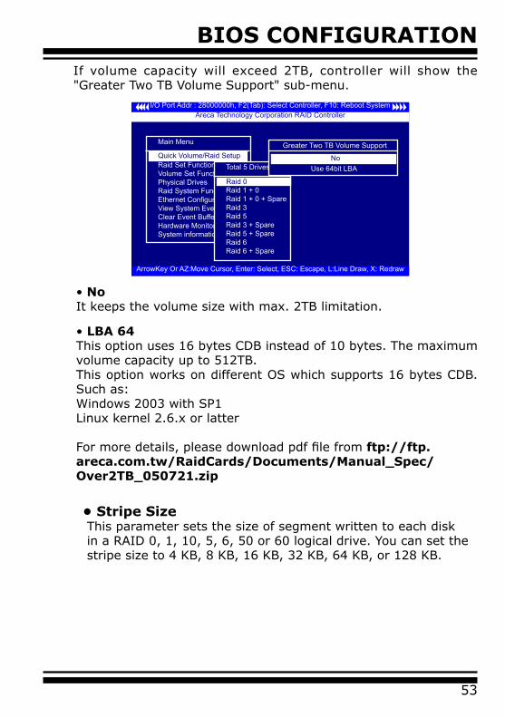
BIOS CONFIGURATION
53
• No It keeps the volume size with max. 2TB limitation.
• LBA 64 This option uses 16 bytes CDB instead of 10 bytes. The maximum volume capacity up to 512TB.This option works on different OS which supports 16 bytes CDB. Such as:Windows 2003 with SP1Linux kernel 2.6.x or latter
For more details, please download pdf file from ftp://ftp.areca.com.tw/RaidCards/Documents/Manual_Spec/Over2TB_050721.zip
• Stripe SizeThis parameter sets the size of segment written to each disk in a RAID 0, 1, 10, 5, 6, 50 or 60 logical drive. You can set the stripe size to 4 KB, 8 KB, 16 KB, 32 KB, 64 KB, or 128 KB.
If volume capacity will exceed 2TB, controller will show the "Greater Two TB Volume Support" sub-menu.
I/O Port Addr : 28000000h, F2(Tab): Select Controller, F10: Reboot System
ArrowKey Or AZ:Move Cursor, Enter: Select, ESC: Escape, L:Line Draw, X: Redraw
Areca Technology Corporation RAID Controller
Main Menu
Raid Set FunctionVolume Set FunctionPhysical DrivesRaid System FunctionEthernet ConfigurationView System EventsClear Event BufferHardware MonitorSystem information
Quick Volume/Raid SetupTotal 5 Drives
Raid 0Raid 1 + 0Raid 1 + 0 + SpareRaid 3Raid 5Raid 3 + SpareRaid 5 + SpareRaid 6Raid 6 + Spare
Raid 0
Greater Two TB Volume Support
No Use 64bit LBA
No
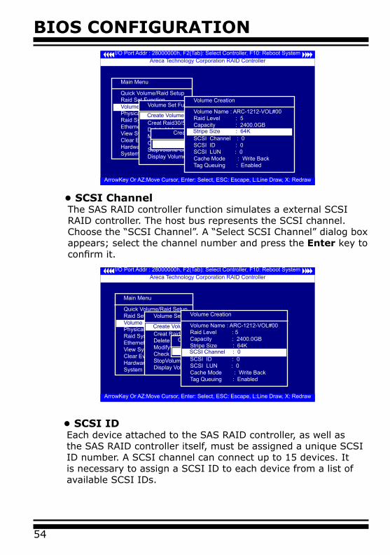
BIOS CONFIGURATION
54
• SCSI IDEach device attached to the SAS RAID controller, as well as the SAS RAID controller itself, must be assigned a unique SCSI ID number. A SCSI channel can connect up to 15 devices. It is necessary to assign a SCSI ID to each device from a list of available SCSI IDs.
• SCSI ChannelThe SAS RAID controller function simulates a external SCSI RAID controller. The host bus represents the SCSI channel. Choose the “SCSI Channel”. A “Select SCSI Channel” dialog box appears; select the channel number and press the Enter key to confirm it.
I/O Port Addr : 28000000h, F2(Tab): Select Controller, F10: Reboot System
ArrowKey Or AZ:Move Cursor, Enter: Select, ESC: Escape, L:Line Draw, X: Redraw
Areca Technology Corporation RAID Controller
Main Menu
Quick Volume/Raid SetupRaid Set FunctionVolume Set FunctionPhysical DrivesRaid System FunctionEthernet ConfigurationView System EventsClear Event BufferHardware MonitorSystem information
Volume Set FunctionVolume Set Functions
Creat Volume SetCreat Raid30/50/60Delete Volume SetModify Volume SetCheck Volume SetStopVolume CheckDisplay Volume Info.
Create Volume Set
Create Volume From Raid Set
Raid Set # 00
Volume Creation
Volume Name : ARC-1212-VOL#00Raid Level : 5Capacity : 2400.0GBStripe Size : 64KSCSI Channel : 0SCSI ID : 0SCSI LUN : 0Cache Mode : Write BackTag Queuing : Enabled
Stripe Size : 64K
I/O Port Addr : 28000000h, F2(Tab): Select Controller, F10: Reboot System
ArrowKey Or AZ:Move Cursor, Enter: Select, ESC: Escape, L:Line Draw, X: Redraw
Areca Technology Corporation RAID Controller
Main Menu
Quick Volume/Raid SetupRaid Set FunctionVolume Set FunctionPhysical DrivesRaid System FunctionEthernet ConfigurationView System EventsClear Event BufferHardware MonitorSystem information
Volume Set FunctionVolume Set Functions
Creat Volume SetCreat Raid30/50/60Delete Volume SetModify Volume SetCheck Volume SetStopVolume CheckDisplay Volume Info.
Create Volume Set
Create Volume From Raid Set
Raid Set # 00
Volume Creation
Volume Name : ARC-1212-VOL#00Raid Level : 5Capacity : 2400.0GBStripe Size : 64KSCSI Channel : 0SCSI ID : 0SCSI LUN : 0Cache Mode : Write BackTag Queuing : Enabled
SCSI Channel : 0
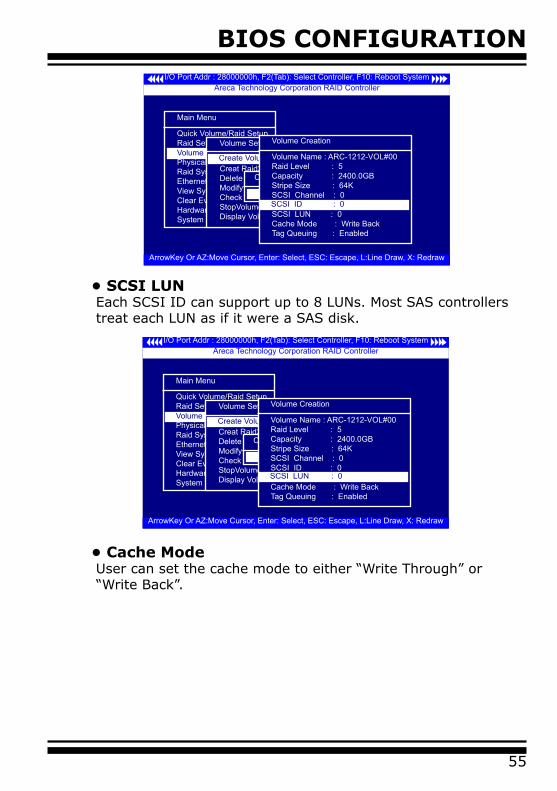
BIOS CONFIGURATION
55
• SCSI LUNEach SCSI ID can support up to 8 LUNs. Most SAS controllers treat each LUN as if it were a SAS disk.
I/O Port Addr : 28000000h, F2(Tab): Select Controller, F10: Reboot System
ArrowKey Or AZ:Move Cursor, Enter: Select, ESC: Escape, L:Line Draw, X: Redraw
Areca Technology Corporation RAID Controller
Main Menu
Quick Volume/Raid SetupRaid Set FunctionVolume Set FunctionPhysical DrivesRaid System FunctionEthernet ConfigurationView System EventsClear Event BufferHardware MonitorSystem information
Volume Set FunctionVolume Set Functions
Creat Volume SetCreat Raid30/50/60Delete Volume SetModify Volume SetCheck Volume SetStopVolume CheckDisplay Volume Info.
Create Volume Set
Create Volume From Raid Set
Raid Set # 00
Volume Creation
Volume Name : ARC-1212-VOL#00Raid Level : 5Capacity : 2400.0GBStripe Size : 64KSCSI Channel : 0SCSI ID : 0SCSI LUN : 0Cache Mode : Write BackTag Queuing : Enabled
SCSI ID : 0
I/O Port Addr : 28000000h, F2(Tab): Select Controller, F10: Reboot System
ArrowKey Or AZ:Move Cursor, Enter: Select, ESC: Escape, L:Line Draw, X: Redraw
Areca Technology Corporation RAID Controller
Main Menu
Quick Volume/Raid SetupRaid Set FunctionVolume Set FunctionPhysical DrivesRaid System FunctionEthernet ConfigurationView System EventsClear Event BufferHardware MonitorSystem information
Volume Set FunctionVolume Set Functions
Creat Volume SetCreat Raid30/50/60Delete Volume SetModify Volume SetCheck Volume SetStopVolume CheckDisplay Volume Info.
Create Volume Set
Create Volume From Raid Set
Raid Set # 00
Volume Creation
Volume Name : ARC-1212-VOL#00Raid Level : 5Capacity : 2400.0GBStripe Size : 64KSCSI Channel : 0SCSI ID : 0SCSI LUN : 0Cache Mode : Write BackTag Queuing : Enabled
SCSI LUN : 0
• Cache ModeUser can set the cache mode to either “Write Through” or “Write Back”.
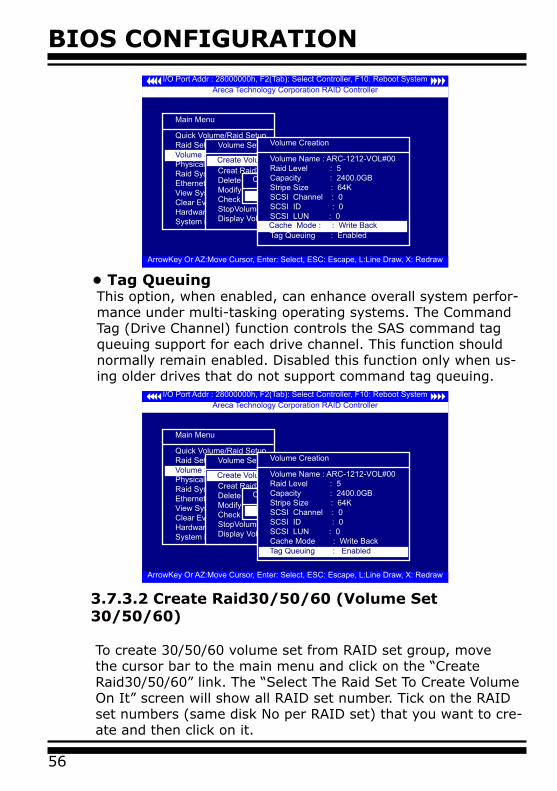
BIOS CONFIGURATION
56
• Tag QueuingThis option, when enabled, can enhance overall system perfor-mance under multi-tasking operating systems. The Command Tag (Drive Channel) function controls the SAS command tag queuing support for each drive channel. This function should normally remain enabled. Disabled this function only when us-ing older drives that do not support command tag queuing.
3.7.3.2 Create Raid30/50/60 (Volume Set 30/50/60)
To create 30/50/60 volume set from RAID set group, move the cursor bar to the main menu and click on the “Create Raid30/50/60” link. The “Select The Raid Set To Create Volume On It” screen will show all RAID set number. Tick on the RAID set numbers (same disk No per RAID set) that you want to cre-ate and then click on it.
I/O Port Addr : 28000000h, F2(Tab): Select Controller, F10: Reboot System
ArrowKey Or AZ:Move Cursor, Enter: Select, ESC: Escape, L:Line Draw, X: Redraw
Areca Technology Corporation RAID Controller
Main Menu
Quick Volume/Raid SetupRaid Set FunctionVolume Set FunctionPhysical DrivesRaid System FunctionEthernet ConfigurationView System EventsClear Event BufferHardware MonitorSystem information
Volume Set FunctionVolume Set Functions
Creat Volume SetCreat Raid30/50/60Delete Volume SetModify Volume SetCheck Volume SetStopVolume CheckDisplay Volume Info.
Create Volume Set
Create Volume From Raid Set
Raid Set # 00
Volume Creation
Volume Name : ARC-1212-VOL#00Raid Level : 5Capacity : 2400.0GBStripe Size : 64KSCSI Channel : 0SCSI ID : 0SCSI LUN : 0Cache Mode : Write BackTag Queuing : EnabledTag Queuing : Enabled
I/O Port Addr : 28000000h, F2(Tab): Select Controller, F10: Reboot System
ArrowKey Or AZ:Move Cursor, Enter: Select, ESC: Escape, L:Line Draw, X: Redraw
Areca Technology Corporation RAID Controller
Main Menu
Quick Volume/Raid SetupRaid Set FunctionVolume Set FunctionPhysical DrivesRaid System FunctionEthernet ConfigurationView System EventsClear Event BufferHardware MonitorSystem information
Volume Set FunctionVolume Set Functions
Creat Volume SetCreat Raid30/50/60Delete Volume SetModify Volume SetCheck Volume SetStopVolume CheckDisplay Volume Info.
Create Volume Set
Create Volume From Raid Set
Raid Set # 00
Volume Creation
Volume Name : ARC-1212-VOL#00Raid Level : 5Capacity : 2400.0GBStripe Size : 64KSCSI Channel : 0SCSI ID : 0SCSI LUN : 0Cache Mode : Write BackTag Queuing : EnabledCache Mode : : Write Back
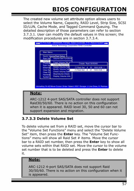
BIOS CONFIGURATION
57
The created new volume set attribute option allows users to select the Volume Name, Capacity, RAID Level, Strip Size, SCSI ID/LUN, Cache Mode, and Tagged Command Queuing. The detailed description of those parameters can refer to section 3.7.3.1. User can modify the default values in this screen; the modification procedures are in section 3.7.3.4.
I/O Port Addr : 28000000h, F2(Tab): Select Controller, F10: Reboot System
ArrowKey Or AZ:Move Cursor, Enter: Select, ESC: Escape, L:Line Draw, X: Redraw
Areca Technology Corporation RAID Controller
Main Menu
Quick Volume/Raid SetupRaid Set FunctionVolume Set FunctionPhysical DrivesRaid System FunctionEthernet ConfigurationView System EventsClear Event BufferHardware MonitorSystem information
Volume Set FunctionVolume Set Functions
Creat Volume SetCreat Raid30/50/60Delete Volume SetModify Volume SetCheck Volume SetStopVolume CheckDisplay Volume Info.
Create Raid30/50/60 Create Raid 30/50/60
[*] Raid Set # 00 1600.0GB 1[ ] Raid Set # 01 1600.0GB 1[*] Raid Set # 01 1600.0GB 1
3.7.3.3 Delete Volume Set
To delete volume set from a RAID set, move the cursor bar to the “Volume Set Functions” menu and select the “Delete Volume Set” item, then press the Enter key. The “Volume Set Func-tions” menu will show all Raid Set # items. Move the cursor bar to a RAID set number, then press the Enter key to show all volume sets within that RAID set. Move the cursor to the volume set number that is to be deleted and press the Enter to delete it.
Note:
ARC-1212 4-port SAS/SATA does not support Raid 30/50/60. There is no action on this configuration when it is appeared.
Note:
ARC-1212 4-port SAS/SATA controller does not support Raid30/50/60. There is no action on this configuration when it is appeared. RAID level 30, 50 and 60 can not support expansion and migration.
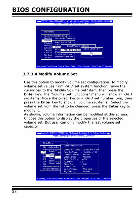
BIOS CONFIGURATION
58
3.7.3.4 Modify Volume Set Use this option to modify volume set configuration. To modify volume set values from RAID set system function, move the cursor bar to the “Modify Volume Set” item, then press the Enter key. The “Volume Set Functions” menu will show all RAID set items. Move the cursor bar to a RAID set number item, then press the Enter key to show all volume set items. Select the volume set from the list to be changed, press the Enter key to modify it. As shown, volume information can be modified at this screen. Choose this option to display the properties of the selected volume set. But user can only modify the last volume set capacity.
I/O Port Addr : 28000000h, F2(Tab): Select Controller, F10: Reboot System
ArrowKey Or AZ:Move Cursor, Enter: Select, ESC: Escape, L:Line Draw, X: Redraw
Areca Technology Corporation RAID Controller
Main Menu
Quick Volume/Raid SetupRaid Set FunctionVolume Set FunctionPhysical DrivesRaid System FunctionEthernet ConfigurationView System EventsClear Event BufferHardware MonitorSystem information
Volume Set FunctionVolume Set Functions
Creat Volume SetCreat Raid30/50/60Delete Volume SetModify Volume SetCheck Volume SetStopVolume CheckDisplay Volume Info.
Delete Volume SetSelect Volume To Delete
ARC-1212-VOL#00(Raid Set #00)Delete Volume Set
NoYes
Controller I/O Port:F3000000h, F2: Select Controller, F10: Reboot System
ArrowKey Or AZ:Move Cursor, Enter: Select, ESC: Escape, L:Line Draw, X: Redraw
Areca Technology Corporation RAID Controller
Main Menu
Quick Volume/Raid SetupRaid Set FunctionVolume Set FunctionPhysical DrivesRaid System FunctionEthernet ConfigurationView System EventsClear Event BufferHardware MonitorSystem Information
Volume Set Function
Volume Set Function
Create Volume SetDelete Volume SetModify Volume SetCheck Volume SetStopVolume Check
Display Volume Info.
Modify volume set.Modify Volume Info in Raid
Raid Set # 01Raid Set # 00
Volume Modification
Volume Set Name : Volume Set # 00Raid Set Name : Raid Set # 00Volume Capacity : 160.1GBVolume State : MigrationSCSI CH/ID/Lun : 0/0/0RAID Level : 6Stripe Size : 64KMember Disk : 4Cache Attribute : Write-BackTag Queuing : Enabled
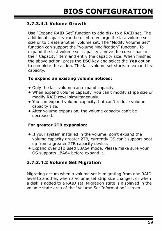
BIOS CONFIGURATION
59
3.7.3.4.1 Volume Growth
Use “Expand RAID Set” function to add disk to a RAID set. The additional capacity can be used to enlarge the last volume set size or to create another volume set. The “Modify Volume Set” function can support the “Volume Modification” function. To expand the last volume set capacity , move the cursor bar to the “ Capacity” item and entry the capacity size. When finished the above action, press the ESC key and select the Yes option to complete the action. The last volume set starts to expand its capacity.
To expand an existing volume noticed:
• Only the last volume can expand capacity.• When expand volume capacity, you can’t modify stripe size or modify RAID revel simultaneously.• You can expand volume capacity, but can’t reduce volume capacity size. • After volume expansion, the volume capacity can't be decreased.
For greater 2TB expansion:
• If your system installed in the volume, don't expand the volume capacity greater 2TB, currently OS can’t support boot up from a greater 2TB capacity device.• Expand over 2TB used LBA64 mode. Please make sure your OS supports LBA64 before expand it.
3.7.3.4.2 Volume Set Migration
Migrating occurs when a volume set is migrating from one RAID level to another, when a volume set strip size changes, or when a disk is added to a RAID set. Migration state is displayed in the volume state area of the “Volume Set Information” screen.
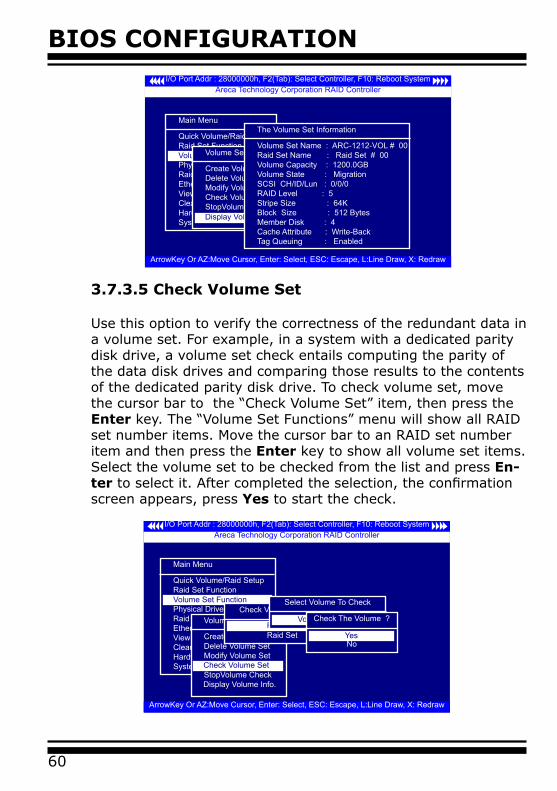
BIOS CONFIGURATION
60
3.7.3.5 Check Volume Set
Use this option to verify the correctness of the redundant data in a volume set. For example, in a system with a dedicated parity disk drive, a volume set check entails computing the parity of the data disk drives and comparing those results to the contents of the dedicated parity disk drive. To check volume set, move the cursor bar to the “Check Volume Set” item, then press the Enter key. The “Volume Set Functions” menu will show all RAID set number items. Move the cursor bar to an RAID set number item and then press the Enter key to show all volume set items. Select the volume set to be checked from the list and press En-ter to select it. After completed the selection, the confirmation screen appears, press Yes to start the check.
I/O Port Addr : 28000000h, F2(Tab): Select Controller, F10: Reboot System
ArrowKey Or AZ:Move Cursor, Enter: Select, ESC: Escape, L:Line Draw, X: Redraw
Areca Technology Corporation RAID Controller
Main Menu
Quick Volume/Raid SetupRaid Set FunctionVolume Set FunctionPhysical DrivesRaid System FunctionEthernet ConfigurationView System EventsClear Event BufferHardware MonitorSystem information
Volume Set Function
Volume Set Function
Create Volume SetDelete Volume SetModify Volume SetCheck Volume SetStopVolume Check
Display Volume Info.
Check Volume Set
Check Volume From Raid Set
Raid Set # 01Raid Set # 00
Select Volume To Check
Volume Set # 00Check The Volume ?
NoYes
I/O Port Addr : 28000000h, F2(Tab): Select Controller, F10: Reboot System
ArrowKey Or AZ:Move Cursor, Enter: Select, ESC: Escape, L:Line Draw, X: Redraw
Areca Technology Corporation RAID Controller
Main Menu
Quick Volume/Raid SetupRaid Set FunctionVolume Set FunctionPhysical DrivesRaid System FunctionEthernet ConfigurationView System EventsClear Event BufferHardware MonitorSystem information
Volume Set FunctionVolume Set Function
Create Volume SetDelete Volume SetModify Volume SetCheck Volume SetStopVolume CheckDisplay Volume Info.
The Volume Set Information
Volume Set Name : ARC-1212-VOL # 00Raid Set Name : Raid Set # 00Volume Capacity : 1200.0GBVolume State : MigrationSCSI CH/ID/Lun : 0/0/0RAID Level : 5Stripe Size : 64KBlock Size : 512 Bytes Member Disk : 4Cache Attribute : Write-BackTag Queuing : Enabled
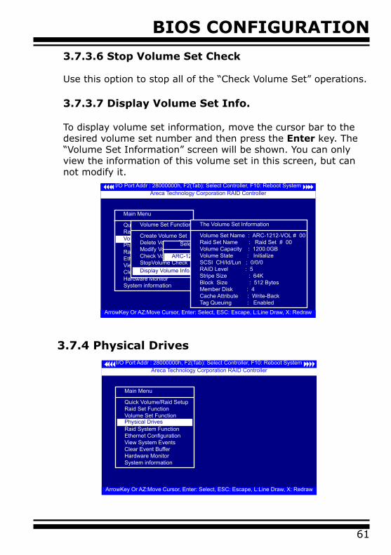
BIOS CONFIGURATION
61
3.7.3.6 Stop Volume Set Check
Use this option to stop all of the “Check Volume Set” operations. 3.7.3.7 Display Volume Set Info.
To display volume set information, move the cursor bar to the desired volume set number and then press the Enter key. The “Volume Set Information” screen will be shown. You can only view the information of this volume set in this screen, but can not modify it.
I/O Port Addr : 28000000h, F2(Tab): Select Controller, F10: Reboot System
ArrowKey Or AZ:Move Cursor, Enter: Select, ESC: Escape, L:Line Draw, X: Redraw
Areca Technology Corporation RAID Controller
Main Menu
Quick Volume/Raid SetupRaid Set FunctionVolume Set FunctionPhysical DrivesRaid System FunctionEthernet ConfigurationView System EventsClear Event BufferHardware MonitorSystem information
Volume Set Function
Volume Set Function
Create Volume SetDelete Volume SetModify Volume SetCheck Volume SetStopVolume CheckDisplay Volume Info.
Select Volume To Display
ARC-12-VOL#00(Raid Set #00)
The Volume Set Information
Volume Set Name : ARC-1212-VOL # 00Raid Set Name : Raid Set # 00Volume Capacity : 1200.0GBVolume State : InitializeSCSI CH/Id/Lun : 0/0/0RAID Level : 5Stripe Size : 64KBlock Size : 512 Bytes Member Disk : 4Cache Attribute : Write-BackTag Queuing : Enabled
3.7.4 Physical DrivesI/O Port Addr : 28000000h, F2(Tab): Select Controller, F10: Reboot System
ArrowKey Or AZ:Move Cursor, Enter: Select, ESC: Escape, L:Line Draw, X: Redraw
Areca Technology Corporation RAID Controller
Main Menu
Quick Volume/Raid SetupRaid Set FunctionVolume Set FunctionPhysical DrivesRaid System FunctionEthernet ConfigurationView System EventsClear Event BufferHardware MonitorSystem information
Physical Drives
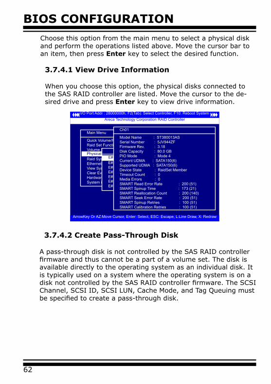
BIOS CONFIGURATION
62
Choose this option from the main menu to select a physical disk and perform the operations listed above. Move the cursor bar to an item, then press Enter key to select the desired function.
3.7.4.1 View Drive Information
When you choose this option, the physical disks connected to the SAS RAID controller are listed. Move the cursor to the de-sired drive and press Enter key to view drive information.
I/O Port Addr : 28000000h, F2(Tab): Select Controller, F10: Reboot System
ArrowKey Or AZ:Move Cursor, Enter: Select, ESC: Escape, L:Line Draw, X: Redraw
Areca Technology Corporation RAID Controller
Main Menu
Quick Volume/Raid SetupRaid Set FunctionVolume Set FunctionPhysical DrivesRaid System FunctionEthernet ConfigurationView System EventsClear Event BufferHardware MonitorSystem information
Physical Drive InformationSelect The Drives
E#1Solt#2 : 500.1GB : HDS725050KLA360E#1Solt#3 : 500.1GB : ST3500630NSE#1Solt#4 : 400.1GB : Hitachi HDT725040VLA360E#1Solt#5 : 400.1GB : Hitachi HDT725040VLA360E#1Solt#6 : 400.1GB : Hitachi HDT725040VLA360E#1Solt#7 : 500.1GB : HDS725050KL360E#1Solt#8 : 500.1GB : ST3500630NS
E#1Solt#2 : 500.1GB : HDS725050KLA360
Ch01
Model Name : ST380013ASSerial Number : 5JV944ZFFirmware Rev. : 3.18Disk Capacity : 80.0 GBPIO Mode : Mode 4Current UDMA : SATA150(6)Supported UDMA : SATA150(6)Device State : RaidSet MemberTimeout Count : 0Media Errors : 0SMART Read Error Rate : 200 (51)SMART Spinup Time : 173 (21)SMART Reallocation Count : 200 (140)SMART Seek Error Rate : 200 (51)SMART Spinup Retries : 100 (51)SMART Calibration Retries : 100 (51)
3.7.4.2 Create Pass-Through Disk
A pass-through disk is not controlled by the SAS RAID controller firmware and thus cannot be a part of a volume set. The disk is available directly to the operating system as an individual disk. It is typically used on a system where the operating system is on a disk not controlled by the SAS RAID controller firmware. The SCSI Channel, SCSI ID, SCSI LUN, Cache Mode, and Tag Queuing must be specified to create a pass-through disk.

BIOS CONFIGURATION
63
3.7.4.3 Modify a Pass-Through Disk
Use this option to modify “Pass-Through Disk Attributes”. To select and modify a pass-through disk from the pool of pass-through disks, move the “Modify Pass-Through Drive” option and then press the Enter key. The “Physical Drive Function” menu will show all pass-through drive number options. Move the cur-sor bar to the desired number and then press the Enter key to show all pass-through disk attributes. Select the parameter from the list to be changed and them press the Enter key to modify it.
3.7.4.4 Delete Pass-Through Disk
I/O Port Addr : 28000000h, F2(Tab): Select Controller, F10: Reboot System
ArrowKey Or AZ:Move Cursor, Enter: Select, ESC: Escape, L:Line Draw, X: Redraw
Areca Technology Corporation RAID Controller
Main Menu
Quick Volume/Raid SetupRaid Set FunctionVolume Set FunctionPhysical DrivesRaid System FunctionEthernet ConfigurationView System EventsClear Event BufferHardware MonitorSystem information
Physical Drive Information
Physical Drive Function
View Drive Information
Modify Pass-Through DiskDelete Pass-Through DiskIdentify Selected DriveIdentify Enclosure
Create Pass-Throught
Select The Drives
E#1Solt#2 : 500.1GB : HDS725050KLA360E#1Solt#3 : 500.1GB : ST3500630NSE#1Solt#4 : 400.1GB : Hitachi HDT725040VLA360E#1Solt#5 : 400.1GB : Hitachi HDT725040VLA360E#1Solt#6 : 400.1GB : Hitachi HDT725040VLA360E#1Solt#7 : 500.1GB : HDS725050KL360E#1Solt#8 : 500.1GB : ST3500630NS
E#1Solt#2 : 500.1GB : HDS725050KLA360Pass-Through Disk Attribute
SCSI ID : 0SCSI LUN : 0Cache Mode : Write BackTag Queuing : Enabled
SCSI Channel : 0Create Pass-Through
NoYes
I/O Port Addr : 28000000h, F2(Tab): Select Controller, F10: Reboot System
ArrowKey Or AZ:Move Cursor, Enter: Select, ESC: Escape, L:Line Draw, X: Redraw
Areca Technology Corporation RAID Controller
Main Menu
Quick Volume/Raid SetupRaid Set FunctionVolume Set FunctionPhysical DrivesRaid System FunctionEthernet ConfigurationView System EventsClear Event BufferHardware MonitorSystem information
Physical Drive Information
Physical Drive Function
View Drive InformationCreate Pass-Through DiskModify Pass-Through Disk
Identify Selected DriveDelete Pass-Through
Select The Drive
E#1Slot#2 : 500.1GB Pass Through HDS725050KL360Delete Pass-Through
NoYes
Are you Sure?
NoYes
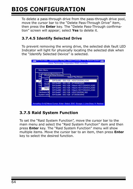
BIOS CONFIGURATION
64
To delete a pass-through drive from the pass-through drive pool, move the cursor bar to the “Delete Pass-Through Drive” item, then press the Enter key. The “Delete Pass-Through confirma-tion” screen will appear; select Yes to delete it.
3.7.4.5 Identify Selected Drive
To prevent removing the wrong drive, the selected disk fault LED Indicator will light for physically locating the selected disk when the “Identify Selected Device” is selected.
I/O Port Addr : 28000000h, F2(Tab): Select Controller, F10: Reboot System
ArrowKey Or AZ:Move Cursor, Enter: Select, ESC: Escape, L:Line Draw, X: Redraw
Areca Technology Corporation RAID Controller
Main Menu
Quick Volume/Raid SetupRaid Set FunctionVolume Set FunctionPhysical DrivesRaid System FunctionEthernet ConfigurationView System EventsClear Event BufferHardware MonitorSystem information
Physical Drive Information
Physical Drive function
View Drive InformationCreate Pass-Through DiskModify Pass-Through DiskDelete Pass-Through Disk Identify Selected Drive
Select The Drives
E#1Solt#2 : 500.1GB : HDS725050KLA360E#1Solt#3 : 500.1GB : ST3500630NSE#1Solt#4 : 400.1GB : Hitachi HDT725040VLA360E#1Solt#5 : 400.1GB : Hitachi HDT725040VLA360E#1Solt#6 : 400.1GB : Hitachi HDT725040VLA360E#1Solt#7 : 500.1GB : HDS725050KL360E#1Solt#8 : 500.1GB : ST3500630NS
E#1Solt#2 : 500.1GB : HDS725050KLA360
3.7.5 Raid System Function
To set the “Raid System Function”, move the cursor bar to the main menu and select the “Raid System Function” item and then press Enter key. The “Raid System Function” menu will show multiple items. Move the cursor bar to an item, then press Enter key to select the desired function.
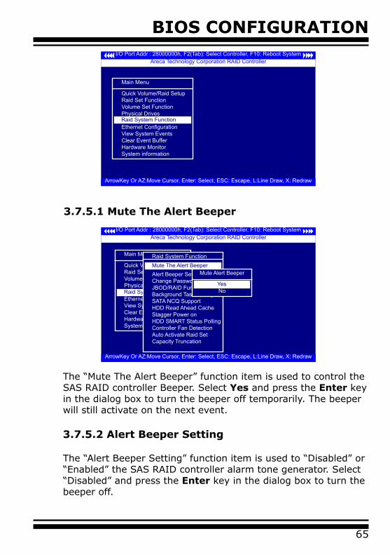
BIOS CONFIGURATION
65
I/O Port Addr : 28000000h, F2(Tab): Select Controller, F10: Reboot System
ArrowKey Or AZ:Move Cursor, Enter: Select, ESC: Escape, L:Line Draw, X: Redraw
Areca Technology Corporation RAID Controller
Main Menu
Quick Volume/Raid SetupRaid Set FunctionVolume Set FunctionPhysical DrivesRaid System FunctionEthernet ConfigurationView System EventsClear Event BufferHardware MonitorSystem information
Raid System Function
3.7.5.1 Mute The Alert Beeper
I/O Port Addr : 28000000h, F2(Tab): Select Controller, F10: Reboot System
ArrowKey Or AZ:Move Cursor, Enter: Select, ESC: Escape, L:Line Draw, X: Redraw
Areca Technology Corporation RAID Controller
Main Menu
Quick Volume/Raid SetupRaid Set FunctionVolume Set FunctionPhysical DrivesRaid System FunctionEthernet ConfigurationView System EventsClear Event BufferHardware MonitorSystem information
Raid System Function
Raid System Function
Alert Beeper SettingChange PasswordJBOD/RAID FunctionBackground Task PrioritySATA NCQ SupportHDD Read Ahead CacheStagger Power onHDD SMART Status PollingController Fan DetectionAuto Activate Raid SetCapacity Truncation
Mute The Alert BeeperMute Alert Beeper
NoYes
The “Mute The Alert Beeper” function item is used to control the SAS RAID controller Beeper. Select Yes and press the Enter key in the dialog box to turn the beeper off temporarily. The beeper will still activate on the next event. 3.7.5.2 Alert Beeper Setting
The “Alert Beeper Setting” function item is used to “Disabled” or “Enabled” the SAS RAID controller alarm tone generator. Select “Disabled” and press the Enter key in the dialog box to turn the beeper off.
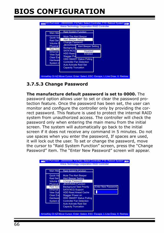
BIOS CONFIGURATION
66
I/O Port Addr : 28000000h, F2(Tab): Select Controller, F10: Reboot System
ArrowKey Or AZ:Move Cursor, Enter: Select, ESC: Escape, L:Line Draw, X: Redraw
Areca Technology Corporation RAID Controller
Main Menu
Quick Volume/Raid SetupRaid Set FunctionVolume Set FunctionPhysical DrivesRaid System FunctionEthernet ConfigurationView System EventsClear Event BufferHardware MonitorSystem information
Raid System Function
Raid System Function
Mute The Alert BeeperAlert Beeper SettingChange PasswordJBOD/RAID FunctionBackground Task PrioritySATA NCQ SupportHDD Read Ahead CacheStagger Power onHDD SMART Status PollingController Fan DetectionAuto Activate Raid SetCapacity Truncation
Alert Beeper Setting
Alert Beeper Setting
EnabledDisabled
3.7.5.3 Change Password
The manufacture default password is set to 0000. The password option allows user to set or clear the password pro-tection feature. Once the password has been set, the user can monitor and configure the controller only by providing the cor-rect password. This feature is used to protect the internal RAID system from unauthorized access. The controller will check the password only when entering the main menu from the initial screen. The system will automatically go back to the initial screen if it does not receive any command in 5 minutes. Do not use spaces when you enter the password, If spaces are used, it will lock out the user. To set or change the password, move the cursor to “Raid System Function” screen, press the “Change Password” item. The “Enter New Password” screen will appear.
I/O Port Addr : 28000000h, F2(Tab): Select Controller, F10: Reboot System
ArrowKey Or AZ:Move Cursor, Enter: Select, ESC: Escape, L:Line Draw, X: Redraw
Areca Technology Corporation RAID Controller
Main Menu
Quick Volume/Raid SetupRaid Set FunctionVolume Set FunctionPhysical DrivesRaid System FunctionEthernet ConfigurationView System EventsClear Event BufferHardware MonitorSystem information
Raid System Function
Raid System Function
Mute The Alert BeeperAlert Beeper SettingChange PasswordJBOD/RAID FunctionBackground Task PrioritySATA NCQ SupportHDD Read Ahead CacheStagger Power onHDD SMART Status PollingController Fan DetectionAuto Activate Raid SetCapacity Truncation
Change Password
Enter New Password
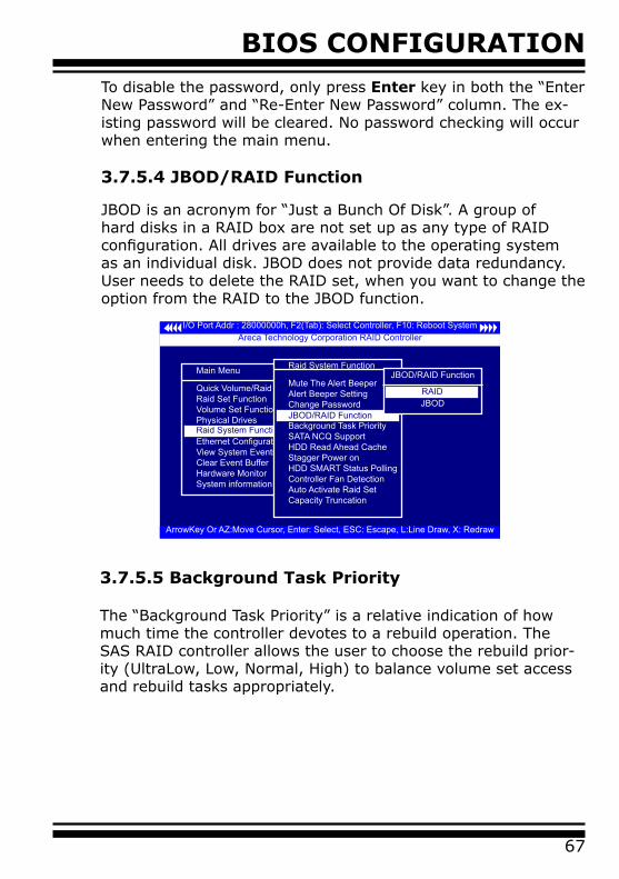
BIOS CONFIGURATION
67
To disable the password, only press Enter key in both the “Enter New Password” and “Re-Enter New Password” column. The ex-isting password will be cleared. No password checking will occur when entering the main menu.
3.7.5.4 JBOD/RAID Function
JBOD is an acronym for “Just a Bunch Of Disk”. A group of hard disks in a RAID box are not set up as any type of RAID configuration. All drives are available to the operating system as an individual disk. JBOD does not provide data redundancy. User needs to delete the RAID set, when you want to change the option from the RAID to the JBOD function.
I/O Port Addr : 28000000h, F2(Tab): Select Controller, F10: Reboot System
ArrowKey Or AZ:Move Cursor, Enter: Select, ESC: Escape, L:Line Draw, X: Redraw
Areca Technology Corporation RAID Controller
Main Menu
Quick Volume/Raid SetupRaid Set FunctionVolume Set FunctionPhysical DrivesRaid System FunctionEthernet ConfigurationView System EventsClear Event BufferHardware MonitorSystem information
Raid System Function
Raid System Function
Mute The Alert BeeperAlert Beeper SettingChange PasswordJBOD/RAID FunctionBackground Task PrioritySATA NCQ SupportHDD Read Ahead CacheStagger Power onHDD SMART Status PollingController Fan DetectionAuto Activate Raid SetCapacity Truncation
JBOD/RAID Function
JBOD/RAID Function
JBODRAID
3.7.5.5 Background Task Priority
The “Background Task Priority” is a relative indication of how much time the controller devotes to a rebuild operation. The SAS RAID controller allows the user to choose the rebuild prior-ity (UltraLow, Low, Normal, High) to balance volume set access and rebuild tasks appropriately.
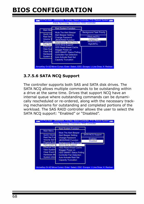
BIOS CONFIGURATION
68
I/O Port Addr : 28000000h, F2(Tab): Select Controller, F10: Reboot System
ArrowKey Or AZ:Move Cursor, Enter: Select, ESC: Escape, L:Line Draw, X: Redraw
Areca Technology Corporation RAID Controller
Main Menu
Quick Volume/Raid SetupRaid Set FunctionVolume Set FunctionPhysical DrivesRaid System FunctionEthernet ConfigurationView System EventsClear Event BufferHardware MonitorSystem information
Raid System Function
Raid System Function
Mute The Alert BeeperAlert Beeper SettingChange PasswordJBOD/RAID FunctionBackground Task PrioritySATA NCQ SupportHDD Read Ahead CacheStagger Power onHDD SMART Status PollingController Fan DetectionAuto Activate Raid SetCapacity Truncation
Background Task Priority
Background Task Priority
UltraLow(5%)
Medium(50%) High(80%)
Low(20%)
3.7.5.6 SATA NCQ Support
The controller supports both SAS and SATA disk drives. The SATA NCQ allows multiple commands to be outstanding within a drive at the same time. Drives that support NCQ have an internal queue where outstanding commands can be dynami-cally rescheduled or re-ordered, along with the necessary track-ing mechanisms for outstanding and completed portions of the workload. The SAS RAID controller allows the user to select the SATA NCQ support: “Enabled” or “Disabled”.
I/O Port Addr : 28000000h, F2(Tab): Select Controller, F10: Reboot System
ArrowKey Or AZ:Move Cursor, Enter: Select, ESC: Escape, L:Line Draw, X: Redraw
Areca Technology Corporation RAID Controller
Main Menu
Quick Volume/Raid SetupRaid Set FunctionVolume Set FunctionPhysical DrivesRaid System FunctionEthernet ConfigurationView System EventsClear Event BufferHardware MonitorSystem information
Raid System Function
Raid System Function
Mute The Alert BeeperAlert Beeper SettingChange PasswordJBOD/RAID FunctionBackground Task PrioritySATA NCQ SupportHDD Read Ahead CacheStagger Power onHDD SMART Status PollingController Fan DetectionAuto Activate Raid SetCapacity Truncation
SATA NCQ Support
SATA NCQ Support
Enabled Disabled

BIOS CONFIGURATION
69
3.7.5.7 HDD Read Ahead Cache
Allow Read Ahead (Default: Enabled)—When Enabled, the drive’s read ahead cache algorithm is used, providing maximum performance under most circumstances.
3.7.5.8 Stagger Power On
In a PC system with only one or two drives, the power can sup-ply enough power to spin up both drives simultaneously. But in systems with more than two drives, the startup current from spinning up the drives all at once can overload the power supply, causing damage to the power supply, disk drives and other sys-tem components. This damage can be avoided by allowing the host to stagger the spin-up of the drives. The SAS/SATA drives have support stagger spin-up capabilities to boost reliability. Stagger spin-up is a very useful feature for managing multiple disk drives in a storage subsystem. It gives the host the abil-ity to spin up the disk drives sequentially or in groups, allowing the drives to come ready at the optimum time without straining the system power supply. Staggering drive spin-up in a multiple drive environment also avoids the extra cost of a power supply designed to meet short-term startup power demand as well as steady state conditions.
Areca RAID controller has included the option for customer to select the disk drives sequentially stagger power up value. The
I/O Port Addr : 28000000h, F2(Tab): Select Controller, F10: Reboot System
ArrowKey Or AZ:Move Cursor, Enter: Select, ESC: Escape, L:Line Draw, X: Redraw
Areca Technology Corporation RAID Controller
Main Menu
Quick Volume/Raid SetupRaid Set FunctionVolume Set FunctionPhysical DrivesRaid System FunctionEthernet ConfigurationView System EventsClear Event BufferHardware MonitorSystem information
Raid System Function
Raid System Function
Mute The Alert BeeperAlert Beeper SettingChange PasswordJBOD/RAID FunctionBackground Task PrioritySATA NCQ SupportHDD Read Ahead CacheStagger Power onHDD SMART Status PollingController Fan DetectionAuto Activate Raid SetCapacity Truncation
HDD Read Ahead Cache
HDD Read Ahead Cache
Enabled Disable Maxtor Disabled
Enabled
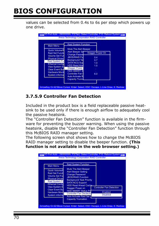
BIOS CONFIGURATION
70
3.7.5.9 Controller Fan Detection
Included in the product box is a field replaceable passive heat-sink to be used only if there is enough airflow to adequately cool the passive heatsink. The “Controller Fan Detection” function is available in the firm-ware for preventing the buzzer warning. When using the passive heatsink, disable the “Controller Fan Detection” function through this McBIOS RAID manager setting.The following screen shot shows how to change the McBIOS RAID manager setting to disable the beeper function. (This function is not available in the web browser setting.)
I/O Port Addr : 28000000h, F2(Tab): Select Controller, F10: Reboot System
ArrowKey Or AZ:Move Cursor, Enter: Select, ESC: Escape, L:Line Draw, X: Redraw
Areca Technology Corporation RAID Controller
Main Menu
Quick Volume/Raid SetupRaid Set FunctionVolume Set FunctionPhysical DrivesRaid System FunctionEthernet ConfigurationView System EventsClear Event BufferHardware MonitorSystem information
Raid System Function
Raid System Function
Mute The Alert BeeperAlert Beeper SettingChange PasswordJBOD/RAID FunctionBackground Task PrioritySATA NCQ SupportHDD Read Ahead CacheStagger Power onHDD SMART Status PollingController Fan DetectionAuto Activate Raid SetCapacity Truncation
Stagger Power on
Stagger Power On
0.4 0.7 1.0 1.5 . . 6.0
I/O Port Addr : 28000000h, F2(Tab): Select Controller, F10: Reboot System
ArrowKey Or AZ:Move Cursor, Enter: Select, ESC: Escape, L:Line Draw, X: Redraw
Areca Technology Corporation RAID Controller
Main Menu
Quick Volume/Raid SetupRaid Set FunctionVolume Set FunctionPhysical DrivesRaid System FunctionEthernet ConfigurationView System EventsClear Event BufferHardware MonitorSystem information
Raid System Function
Raid System Function
Mute The Alert BeeperAlert Beeper SettingChange PasswordJBOD/RAID FunctionBackground Task PrioritySATA NCQ SupportHDD Read Ahead CacheStagger Power onHDD SMART Status PollingController Fan DetectionAuto Activate Raid SetCapacity Truncation
Controller Fan Dectection
Controller Fan Detection
EnabledDisabled
values can be selected from 0.4s to 6s per step which powers up one drive.
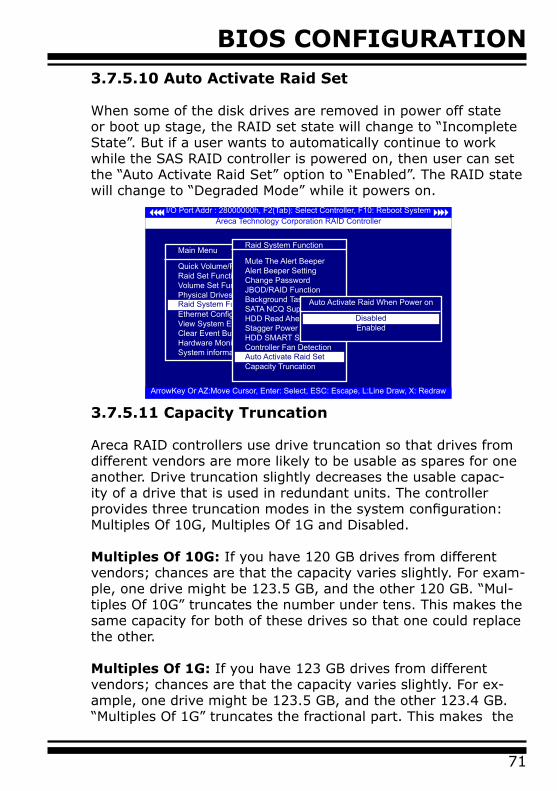
BIOS CONFIGURATION
71
3.7.5.10 Auto Activate Raid Set When some of the disk drives are removed in power off state or boot up stage, the RAID set state will change to “Incomplete State”. But if a user wants to automatically continue to work while the SAS RAID controller is powered on, then user can set the “Auto Activate Raid Set” option to “Enabled”. The RAID state will change to “Degraded Mode” while it powers on.
3.7.5.11 Capacity Truncation
Areca RAID controllers use drive truncation so that drives from different vendors are more likely to be usable as spares for one another. Drive truncation slightly decreases the usable capac-ity of a drive that is used in redundant units. The controller provides three truncation modes in the system configuration: Multiples Of 10G, Multiples Of 1G and Disabled. Multiples Of 10G: If you have 120 GB drives from different vendors; chances are that the capacity varies slightly. For exam-ple, one drive might be 123.5 GB, and the other 120 GB. “Mul-tiples Of 10G” truncates the number under tens. This makes the same capacity for both of these drives so that one could replace the other. Multiples Of 1G: If you have 123 GB drives from different vendors; chances are that the capacity varies slightly. For ex-ample, one drive might be 123.5 GB, and the other 123.4 GB. “Multiples Of 1G” truncates the fractional part. This makes the
I/O Port Addr : 28000000h, F2(Tab): Select Controller, F10: Reboot System
ArrowKey Or AZ:Move Cursor, Enter: Select, ESC: Escape, L:Line Draw, X: Redraw
Areca Technology Corporation RAID Controller
Main Menu
Quick Volume/Raid SetupRaid Set FunctionVolume Set FunctionPhysical DrivesRaid System FunctionEthernet ConfigurationView System EventsClear Event BufferHardware MonitorSystem information
Raid System Function
Raid System Function
Mute The Alert BeeperAlert Beeper SettingChange PasswordJBOD/RAID FunctionBackground Task PrioritySATA NCQ SupportHDD Read Ahead CacheStagger Power onHDD SMART Status PollingController Fan DetectionAuto Activate Raid SetCapacity TruncationAuto Activate Raid Set
Auto Activate Raid When Power on
EnabledDisabled

BIOS CONFIGURATION
72
same capacity for both of these drives so that one could replace the other.
No Truncation: It does not truncate the capacity.
3.7.6 Ethernet Configuration
Use this feature to set the controller Ethernet port configura-tion. It is not necessary to create reserved disk space on any hard disk for the Ethernet port and HTTP service to function; these functions are built into the controller firmware.move the cursor bar to the main menu “Ethernet Configuration Function” item and then press the Enter key. The “Ethernet Configuration” menu appears on the screen. Move the cursor bar to an item, then press Enter key to select the desired function.
I/O Port Addr : 28000000h, F2(Tab): Select Controller, F10: Reboot System
ArrowKey Or AZ:Move Cursor, Enter: Select, ESC: Escape, L:Line Draw, X: Redraw
Areca Technology Corporation RAID Controller
Main Menu
Quick Volume/Raid SetupRaid Set FunctionVolume Set FunctionPhysical DrivesRaid System FunctionEthernet ConfigurationView System EventsClear Event BufferHardware MonitorSystem information
Ethernet Configuration
Main Menu
Quick Volume/Raid SetupRaid Set FunctionVolume Set FunctionPhysical DrivesRaid System FunctionEthernet ConfigurationView System EventsClear Event BufferHardware MonitorSystem information
Raid System Function
I/O Port Addr : 28000000h, F2(Tab): Select Controller, F10: Reboot System
ArrowKey Or AZ:Move Cursor, Enter: Select, ESC: Escape, L:Line Draw, X: Redraw
Areca Technology Corporation RAID Controller
Raid System Function
Mute The Alert BeeperAlert Beeper SettingChange PasswordJBOD/RAID FunctionBackground Task PrioritySATA NCQ SupportHDD Read Ahead CacheStagger Power onHDD SMART Status PollingController Fan DetectionAuto Activate Raid SetCapacity TruncationCapacity Truncation
Truncate Disk Capacity
To Multiples of 10G To Multiples of 1G No Truncation To Multiples of 1G

BIOS CONFIGURATION
73
3.7.6.1 DHCP Function
DHCP (Dynamic Host Configuration Protocol) allows network ad-ministrators centrally manage and automate the assignment of IP (Internet Protocol) addresses on a computer network. When using the TCP/IP protocol (Internet protocol), it is necessary for a computer to have a unique IP address in order to communi-cate to other computer systems. Without DHCP, the IP address must be entered manually at each computer system. DHCP lets a network administrator supervise and distribute IP addresses from a central point. The purpose of DHCP is to provide the automatic (dynamic) allocation of IP client configurations for a specific time period (called a lease period) and to minimize the work necessary to administer a large IP network. To manually configure the IP address of the controller, move the cursor bar to DHCP Function item, then press Enter key to show the DHCP setting. Select the “Disabled” or “Enabled” option to enable or disable the DHCP function. If DHCP is disabled, it will be neces-sary to manually enter a static IP address that does not conflict with other devices on the network.
I/O Port Addr : 28000000h, F2(Tab): Select Controller, F10: Reboot System
ArrowKey Or AZ:Move Cursor, Enter: Select, ESC: Escape, L:Line Draw, X: Redraw
Areca Technology Corporation RAID Controller
Main Menu
Quick Volume/Raid SetupRaid Set FunctionVolume Set FunctionPhysical DrivesRaid System FunctionEthernet ConfigurationView System EventsClear Event BufferHardware MonitorSystem information
Ethernet Configuration
Ethernet Configuration
DHCP Function : EnableLocal IP Address : 192.168.001.100HTTP Port Number : 80 Telnet Port Number : 23SMTP Port Number : 25EtherNet Address : 00. 04. D9.7F .FF. FF
DHCP Function : Enable Select DHCP Setting
EnabledDisabled
3.7.6.2 Local IP address
If you intend to set up your client computers manually (noDHCP), make sure that the assigned IP address is in the samerange as the default router address and that it is unique to yourprivate network. However, it is highly recommend to use DHCPif that option is available on your network. An IP address alloca-tion scheme will reduce the time it takes to set-up client com-

BIOS CONFIGURATION
74
I/O Port Addr : 28000000h, F2(Tab): Select Controller, F10: Reboot System
ArrowKey Or AZ:Move Cursor, Enter: Select, ESC: Escape, L:Line Draw, X: Redraw
Areca Technology Corporation RAID Controller
Main Menu
Quick Volume/Raid SetupRaid Set FunctionVolume Set FunctionPhysical DrivesRaid System FunctionEthernet ConfigurationView System EventsClear Event BufferHardware MonitorSystem information
Ethernet Configuration
Ethernet Configuration
DHCP Function : EnableLocal IP Address : 192.168.001.100HTTP Port Number : 80 Telnet Port Number : 23SMTP Port Number : 25EtherNet Address : 00. 04. D9.7F .FF. FF
Local IP Address : 192.168.001.100
Edit The Local IP Address
92.168.001.1001
puters and eliminate the possibilities of administrative errorsand duplicate addresses. To manually configure the IP addressof the controller, move the cursor bar to Local IP address item, then press the Enter key to show the default address setting in the RAID controller. You can then reassign the static IP address of the controller.
I/O Port Addr : 28000000h, F2(Tab): Select Controller, F10: Reboot System
ArrowKey Or AZ:Move Cursor, Enter: Select, ESC: Escape, L:Line Draw, X: Redraw
Areca Technology Corporation RAID Controller
Main Menu
Quick Volume/Raid SetupRaid Set FunctionVolume Set FunctionPhysical DrivesRaid System FunctionEthernet ConfigurationView System EventsClear Event BufferHardware MonitorSystem information
Ethernet Configuration
Ethernet Configuration
DHCP Function : EnableLocal IP Address : 192.168.001.100HTTP Port Number : 80 Telnet Port Number : 23SMTP Port Number : 25EtherNet Address : 00. 04. D9.7F .FF. FF
HTTP Port Number : 80
Edit The HTTP Port Number
00800
3.7.6.3 HTTP Port Number
To manually configure the “HTTP Port Number” of the controller, move the cursor bar to “HTTP Port Number” item, then press the Enter key to show the default address setting in the RAID con-troller. Then You can reassign the default “HTTP Port Number” of the controller.
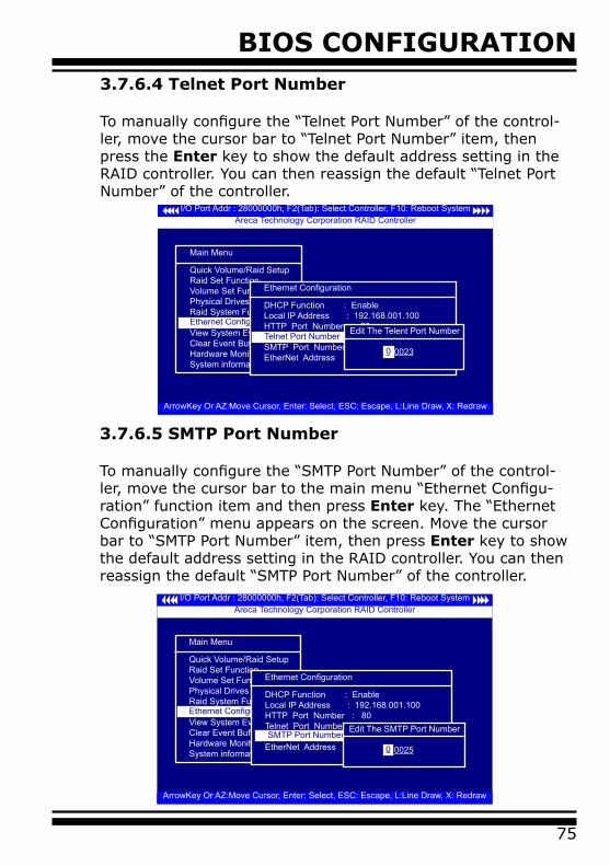
BIOS CONFIGURATION
75
I/O Port Addr : 28000000h, F2(Tab): Select Controller, F10: Reboot System
ArrowKey Or AZ:Move Cursor, Enter: Select, ESC: Escape, L:Line Draw, X: Redraw
Areca Technology Corporation RAID Controller
Main Menu
Quick Volume/Raid SetupRaid Set FunctionVolume Set FunctionPhysical DrivesRaid System FunctionEthernet ConfigurationView System EventsClear Event BufferHardware MonitorSystem information
Ethernet Configuration
Ethernet Configuration
DHCP Function : EnableLocal IP Address : 192.168.001.100HTTP Port Number : 80 Telent Port Number : 23SMTP Port Number : 25EtherNet Address : 00. 04. D9.7F .FF. FF
Telnet Port Number : 23 Edit The Telent Port Number
00230
3.7.6.4 Telnet Port Number
To manually configure the “Telnet Port Number” of the control-ler, move the cursor bar to “Telnet Port Number” item, then press the Enter key to show the default address setting in the RAID controller. You can then reassign the default “Telnet Port Number” of the controller.
I/O Port Addr : 28000000h, F2(Tab): Select Controller, F10: Reboot System
ArrowKey Or AZ:Move Cursor, Enter: Select, ESC: Escape, L:Line Draw, X: Redraw
Areca Technology Corporation RAID Controller
Main Menu
Quick Volume/Raid SetupRaid Set FunctionVolume Set FunctionPhysical DrivesRaid System FunctionEthernet ConfigurationView System EventsClear Event BufferHardware MonitorSystem information
Ethernet Configuration
Ethernet Configuration
DHCP Function : EnableLocal IP Address : 192.168.001.100HTTP Port Number : 80 Telnet Port Number : 23SMTP Port Number : 25EtherNet Address : 00. 04. D9.7F .FF. FF SMTP Port Number : 25
Edit The SMTP Port Number
00250
3.7.6.5 SMTP Port Number
To manually configure the “SMTP Port Number” of the control-ler, move the cursor bar to the main menu “Ethernet Configu-ration” function item and then press Enter key. The “Ethernet Configuration” menu appears on the screen. Move the cursor bar to “SMTP Port Number” item, then press Enter key to show the default address setting in the RAID controller. You can then reassign the default “SMTP Port Number” of the controller.

BIOS CONFIGURATION
76
3.7.6.6 Ethernet Address
Each Ethernet port has its unique Mac address, which is also factory assigned. Usually, Ethernet address is used to uniquely identify a port in the Ethernet network.
I/O Port Addr : 28000000h, F2(Tab): Select Controller, F10: Reboot System
ArrowKey Or AZ:Move Cursor, Enter: Select, ESC: Escape, L:Line Draw, X: Redraw
Areca Technology Corporation RAID Controller
Main Menu
Quick Volume/Raid SetupRaid Set FunctionVolume Set FunctionPhysical DrivesRaid System FunctionEthernet ConfigurationView System EventsClear Event BufferHardware MonitorSystem information
Ethernet Configuration
Ethernet Configuration
DHCP Function : EnableLocal IP Address : 192.168.001.100HTTP Port Number : 80 Telnet Port Number : 23SMTP Port Number : 25EtherNet Address : 00.04.D9.7F.FF.FF EtherNet Address : 00.04.D9.7F.FF.FF
I/O Port Addr : 28000000h, F2(Tab): Select Controller, F10: Reboot System
ArrowKey Or AZ:Move Cursor, Enter: Select, ESC: Escape, L:Line Draw, X: Redraw
Areca Technology Corporation RAID Controller
Main Menu
Quick Volume/Raid SetupRaid Set FunctionVolume Set FunctionPhysical DrivesRaid System FunctionEthernet ConfigurationView System EventsClear Event BufferHardware MonitorSystem information
View System Function
Time Device Event Type ElapseTime Errors
2007-1-1 12:00:00 ARC-1680-VO#00 Raid Powered On2007-1-1 12:00:00 H/W Monitor Raid Powered On2007-1-1 12:00:00 H/W Monitor Raid Powered On
3.7.7 View System Events
To view the SAS RAID controller’s system events information, move the cursor bar to the main menu and select the “View System Events” link, then press the Enter key. The SAS RAID controller’s events screen appear.
Choose this option to view the system events information: Timer, Device, Event type, Elapsed Time, and Errors. The RAID system does not have a build-in real time clock. The time information is the relative time from the SAS RAID controller powered on.
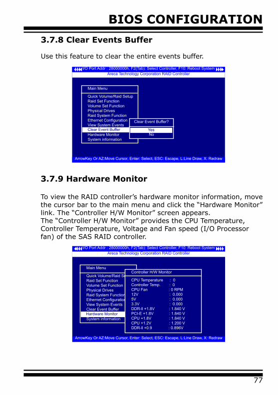
BIOS CONFIGURATION
77
I/O Port Addr : 28000000h, F2(Tab): Select Controller, F10: Reboot System
ArrowKey Or AZ:Move Cursor, Enter: Select, ESC: Escape, L:Line Draw, X: Redraw
Areca Technology Corporation RAID Controller
Main Menu
Quick Volume/Raid SetupRaid Set FunctionVolume Set FunctionPhysical DrivesRaid System FunctionEthernet ConfigurationView System EventsClear Event BufferHardware MonitorSystem information
Clear Event Buffer
Clear Event Buffer?
NoYes
3.7.8 Clear Events Buffer
Use this feature to clear the entire events buffer.
3.7.9 Hardware Monitor
To view the RAID controller’s hardware monitor information, move the cursor bar to the main menu and click the “Hardware Monitor” link. The “Controller H/W Monitor” screen appears.The “Controller H/W Monitor” provides the CPU Temperature, Controller Temperature, Voltage and Fan speed (I/O Processor fan) of the SAS RAID controller.
I/O Port Addr : 28000000h, F2(Tab): Select Controller, F10: Reboot System
ArrowKey Or AZ:Move Cursor, Enter: Select, ESC: Escape, L:Line Draw, X: Redraw
Areca Technology Corporation RAID Controller
Main Menu
Quick Volume/Raid SetupRaid Set FunctionVolume Set FunctionPhysical DrivesRaid System FunctionEthernet ConfigurationView System EventsClear Event BufferHardware MonitorSystem informationHardware Monitor
Controller H/W Monitor
CPU Temperature : 0Controller Temp. : 0CPU Fan : 0 RPM12V : 0.0005V : 0.0003.3V : 0.000DDR-ll +1.8V : 1.840 VPCI-E +1.8V : 1.840 VCPU +1.8V : 1.840 VCPU +1.2V : 1.200 VDDR-ll +0.9 : 0.896V
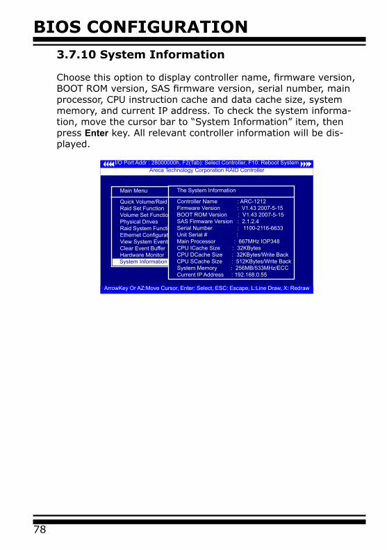
BIOS CONFIGURATION
78
3.7.10 System Information
Choose this option to display controller name, firmware version, BOOT ROM version, SAS firmware version, serial number, main processor, CPU instruction cache and data cache size, system memory, and current IP address. To check the system informa-tion, move the cursor bar to “System Information” item, then press Enter key. All relevant controller information will be dis-played.
I/O Port Addr : 28000000h, F2(Tab): Select Controller, F10: Reboot System
ArrowKey Or AZ:Move Cursor, Enter: Select, ESC: Escape, L:Line Draw, X: Redraw
Areca Technology Corporation RAID Controller
Main Menu
Quick Volume/Raid SetupRaid Set FunctionVolume Set FunctionPhysical DrivesRaid System FunctionEthernet ConfigurationView System EventsClear Event BufferHardware MonitorSystem informationSystem Information
The System Information
Controller Name : ARC-1212Firmware Version : V1.43 2007-5-15BOOT ROM Version : V1.43 2007-5-15SAS Firmware Version : 2.1.2.4Serial Number : 1100-2116-6633Unit Serial # :Main Processor : 667MHz IOP348CPU ICache Size : 32KBytesCPU DCache Size : 32KBytes/Write BackCPU SCache Size : 512KBytes/Write BackSystem Memory : 256MB/533MHz/ECCCurrent IP Address : 192.168.0.55
DRIVER INSTALLATION
79
4. Driver InstallationThis chapter describes how to install the SAS RAID controller driver to your operating system. The installation procedures use the following terminology:
Installing operating system on the SAS/SATA Volume
If you have a new drive configuration without an operating system and want to install operating system on a disk drive managed by the SAS RAID Controller. The driver installation is a part of the operating system installation.
Installing SAS RAID controller into an existing operating sys-tem
The computer has an existing operating system installed and the SAS RAID controller is being installed as a secondary controller.
Have all required system hardware and software components on hand before proceeding with the setup and installation.Materials required:
• Microsoft Windows 2000/XP/2003/Vista, or Linux, or FreeBSD in- stallation CD• SAS RAID controller software CD• SAS RAID controller
4.1 Creating the Driver Diskettes
The software CD disc shipped with the SAS RAID controller is a self-booting CD. In order to created driver diskettes for Windows, Linux, and FreeBSD installation drivers, your system is required to support booting from the CD-ROM.
If you do not have the software CD disc with the package, contact your local dealers or you can also download the latest version driv-ers for Windows 2000/XP/2003/Vista, Linux, FreeBSD, Solaris and Mac from the Areca web site at http://www.areca.com.tw
These driver diskettes are intended for use with new operating

DRIVER INSTALLATION
80
system installations. Determine the correct kernel version and identify which diskette images contain drivers for that kernel. If the driver file ends in .img, create the appropriate driver diskette using “dd” utility. The following steps are required to create the driver diskettes:
1. The computer system BIOS must be set to boot-up from the CD-ROM.2. Insert the SATA controller driver CD disc into the CD-ROM drive.3. The system will boot-up from CD-ROM Drive.
Note:
It will take about 5 minutes to boot up the Knoppix GNU/Linux, Live Linux CD.
4. To create the driver diskette, for example: making the Cen- tOS 5 driver diskette.
4a. Execute xterm by clicking the XTerm icon on left-bottom toolbar.4b. Change the path to the specific driver image. cd /cdrom/PACKAGES/Linux/DRIVER/CentOS_54c. Dump the driver image into floppy diskette using "dd" util -ity, Command format: dd if=<image file> of= <destination> dd if=driver.img of=/dev/fd04d. When the operation is complete, the following messages are shown. 2880+0 records in 2880+0 records out 1474560 bytes (1.5 MB) copied, 97.5903 seconds, 15.1 kB/s
The driver diskette is made now. Proceed to the following instruction for installation procedures.
DRIVER INSTALLATION
81
4.2 Driver Installation for Windows
The SAS RAID controller can be used with Microsoft Windows 2000/XP/2003/Vista. The SAS RAID controllers support SCSI Miniport and StorPort Drivers for Windows Server 2003/Vista.
4.2.1 New Storage Device Drivers in Windows 2003/XP-64/Vista
The Storport driver is new to Windows Server 2003/XP-64/Vista. Storport implements a new architecture designed for better per-formance with RAID systems and in Storage Area Network (SAN) environments. Storport delivers higher I/O throughput, enhanced manageability, and an improved miniport interface. Storport better utilizes faster adapters through the use of reduced Delay Procedure Call (DPC) and improved queue management.
4.2.2 Install Windows 2000/XP/2003/Vista on a SAS/SATA RAID Volume
The following instructions explain how to install the SAS RAID controller device driver. For completed details on installing Win-dows, see the Windows User’s Manual.
4.2.2.1 Installation Procedures
The following procedures detail installing the SAS RAID control-ler driver while installing Windows 2000/XP/2003/Vista. Have your bootable Microsoft Windows 2000/XP/2003/Vista CD and follow the required procedure below to install SAS RAID control-ler:
1. Make sure you follow the instructions in Chapter 2 “Hardware Installation” to install the controller and connect the disk drives or enclosure.
2. Start the system and then press Tab+F6 to access the Mc-BIOS RAID manager. Use the McBIOS RAID manager to create the RAID set and volume set to which you will install Windows. For details, see Chapter 3 “McBIOS RAID manager”. Once a

DRIVER INSTALLATION
82
Note:
The computer system BIOS must support bootable from CD-ROM.
volume set is created and configured, continue with next step to install the operating system.
3. Insert the Windows setup CD and reboot the system to begin the Windows installation.
4. Press F6 key as soon as the Windows screen shows ”Setup is inspecting your computer’s hardware configuration”. A mes-sage stating “Press F6 to specify thrid-party RAID controller” will display during this time. This must be done or else the Windows installer will not prompt for the driver from the SAS RAID con-troller and the driver diskette will not be recognized.
5. The next screen will show: “Setup could not determine the type of one or more mass storage device installed in your sys-tem. ”Selected “specify additional SCSI controller” by pressing S.
6. Window will prompt to place the “Manufacturer-supplied hardware support disk” into floppy drive A:. Insert the SAS RAID series driver diskette in drive “A:” and press Enter key.
7. Window will check the floppy; select the correct card and CPU type for your hardware from the listing and press Enter key to install it.
8. After Windows scans the hardware and finds the controller, it will display:“Setup will load support for the following mass storage devices:”“ARECA[Windows X86-64 Storport] SATA/SAS PCI RAID Host Controller(RAID6-Engine Inside)”. Press Enter key to continue and copy the driver files. From this point on, simply follow the Microsoft Windows installation procedure. Follow the on-screen instructions, responding as needed, to complete the installation.

DRIVER INSTALLATION
83
9. After the installation is completed, reboot the system to load the new driver/operating system.
10. See Chapter 5 in this manual to customize your RAID vol-ume sets using McRAID Storage Manager.
4.2.2.2 Making Volume Sets Available to Windows System
When you reboot the system, log in as a system administrator. Continue with the following steps to make any additional volume sets or pass-through disks accessible to Windows. This proce-dure assumes that the SAS RAID controller hardware, driver, and Windows are installed and operational in your system.
1. Partition and format the new volume set or disks using “Disk Administrator”:
a. Choose “Administrative Tools” from the “Start” menu.b. Choose “Computer Management” from the “Administrative Tools” menu.c. Select “Storage”.d. Select “Disk Management”.
2. Follow the on-screen prompts to write a signature to the drive.
3. Right click on the disk drive and select “Create Volume” from the menu.
4. Follow the on-screen prompts to create a volume set and to give a disk drive letter.
4.2.3 Installing controller into an existing Win-dows 2000/XP/2003/Vista Installation
In this scenario, you are installing the controller in an existing Windows system. To install the driver:

DRIVER INSTALLATION
84
1. Follow the instructions in Chapter 2, the Hardware Installation Chapter, to install the controller and connect the disk drives or enclosure.
2. Start the system and then press Tab+F6 to enter the con-troller McBIOS RAID manager. Use the configuration utility to create the RAID set and volume set. For details, see Chapter 3, McBIOS RAID Manager. Once a volume set is created and config-ured, continue with installation of the driver.
3. Re-Boot Windows and the OS will recognize the SAS RAID controller and launch the “Found New Hardware Wizard”, which guides you in installing the SAS RAID driver.
4. The “Upgrade Device Driver Wizard” will pop-up and provide a choice of how to proceed. Choose “Display a list of known driv-ers for this device, so that you can choose a specific driver.” and click on “Next”.
5. When the next screen queries the user about utilizing the cur-rently installed driver, click on the “Have Disk” button.
6. When the “Install From Disk” dialog appears, insert the SAS RAID controller driver diskette or the shipping software CD and type-in or browse to the correct path for the “Copy Manufactur-er’s Files from:” dialog box.
7. After specifying the driver location, the previous dialog box will appear showing the selected driver to be installed. Click the “Next” button. 8. The “Digital Signature Not Found” screen will appear. Click on Yes option to continue the installation.
9. Windows automatically copies the appropriate driver files and rebuilds its driver database.
10. The “Found New Hardware Wizard” summary screen ap-pears; click the “Finish” button.
11. The “System Settings Change” dialog box appears. Remove
DRIVER INSTALLATION
85
the diskette from the drive and click Yes to restart the computer to load the new drivers.
12. See Chapter 5 in this manual for information on customizing your RAID volumes using McRAID Storage Manager.
4.2.3.1 Making Volume Sets Available to Windows System
When you reboot the system, log in as a system administrator. The following steps show how to make any new disk arrays or independent disks accessible to Windows 2000/XP/2003/Vista. This procedure assumes that the SAS RAID controller hardware, driver, and Windows are installed and operational in your sys-tem.
1. Partition and format the new arrays or disks using “Disk Ad-ministrator”:
a. Choose “Administrative Tools” from the “Start” menu.b. Choose “Computer Management” from the “Administrative Tools” menu.c. Select “Storage”.d. Select “Disk Management”.
2. Follow the on-screen prompts to write a signature to the drive.
3. Right click on the drive and select “Create Volume” from the menu.
4. Follow the on-screen prompts to create a volume set and to assign a disk drive letter.
4.2.4 Uninstall controller from Windows 2000/XP/2003/Vista
To remove the SAS RAID controller driver from the Windows sys-tem, follow the instructions below.

DRIVER INSTALLATION
86
1. Ensure that you have closed all applications and are logged in with administrative rights.
2. Open “Control Panel” and start the “Add/Remove Program” icon and uninstall and software for the SAS RAID controller.
3. Go to “Control Panel” and select “System”. Select the “Hard-ware” tab and then click the “Device Manager” button. In device manager, expand the “SCSI and RAID Controllers” section. Right click on the Areca SAS RAID controller and select “Uninstall”.
4. Click Yes to confirm removing the SAS RAID driver. The prompt to restart the system will then be displayed.
4.3 Driver Installation for Linux
This chapter describes how to install the SAS RAID controller driver to Red Hat Linux, SuSE and other versions of Linux. Before install-ing the SAS RAID driver to the Linux, complete the following ac-tions:
1. Install and configure the controller and hard disk drives accord-ing to the instructions in Chapter 2 Hardware Installation.
2. Start the system and then press Tab+F6 to enter the McBIOS RAID manager configuration utility. Using the McBIOS RAID man-ager to create the RAID set and volume set. For details, see Chap-ter 3, McBIOS RAID Manager.
If you are using a Linux distribution for which there is not a com-piled driver available from Areca, you can copy the source from the SAS software CD or download the source from the Areca website and compile a new driver.
Compiled and tested drivers for Red Hat and SuSE Linux are includ-ed on the shipped CD. You can download updated versions of com-piled and tested drivers for RedHat or SuSE Linux from the Areca web site at http://www.areca.com.tw. Included in these downloads is the Linux driver source, which can be used to compile the updat-
DRIVER INSTALLATION
87
ed version driver for RedHat, SuSE and other versions of Linux. Please refer to the “readme.txt” file on the included Areca CD or website to make driver diskette and to install driver to the system.
4.4 Driver Installation for FreeBSD
This chapter describes how to install the SAS RAID controller driver to FreeBSD. Before installing the SAS RAID driver to FreeBSD, complete following actions:
1. Install and configure the controller and hard disk drives accord-ing to the instructions in Chapter 2, Hardware Installation.
2. Start the system and then press Tab+F6 to enter the McBIOS RAID Manager configuration utility. Use the McBIOS RAID manager to create the RAID set and volume set. For details, see Chapter 3, McBIOS RAID Manager.
The supplied software CD that came with the SAS RAID control-ler includes compiled and tested drivers for FreeBSD 4.x (4.2 and onwards) and 5.x (5.2 and onwards). To check if a more current version driver is available, please see the Areca web site at http://www.areca.com.tw.
Please refer to the “readme.txt” file on the SAS RAID controller software CD or website to make driver diskette and to install driver to the system.
4.5 Driver Installation for Solaris
Please refer to the “readme.txt” file on the software CD or website: http:/www.areca.com.tw
4.6 Driver Installation for Mac X
After hardware installation, the SATA disk drives connected to the SATA RAID Adapter must be configured and the volume set units initialized by the controller before they are ready to use by the system.
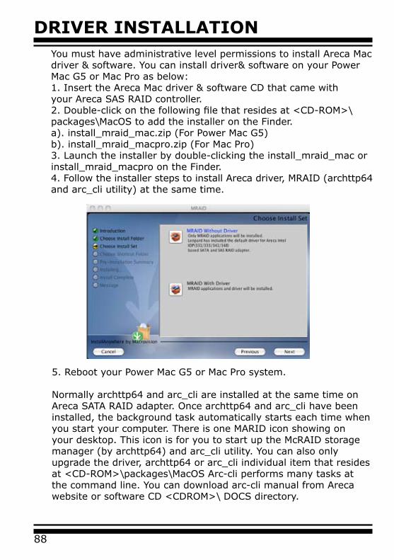
DRIVER INSTALLATION
88
You must have administrative level permissions to install Areca Macdriver & software. You can install driver& software on your PowerMac G5 or Mac Pro as below:1. Insert the Areca Mac driver & software CD that came withyour Areca SAS RAID controller.2. Double-click on the following file that resides at <CD-ROM>\packages\MacOS to add the installer on the Finder.a). install_mraid_mac.zip (For Power Mac G5)b). install_mraid_macpro.zip (For Mac Pro)3. Launch the installer by double-clicking the install_mraid_mac orinstall_mraid_macpro on the Finder.4. Follow the installer steps to install Areca driver, MRAID (archttp64 and arc_cli utility) at the same time.
5. Reboot your Power Mac G5 or Mac Pro system.
Normally archttp64 and arc_cli are installed at the same time onAreca SATA RAID adapter. Once archttp64 and arc_cli have been installed, the background task automatically starts each time when you start your computer. There is one MARID icon showing on your desktop. This icon is for you to start up the McRAID storage manager (by archttp64) and arc_cli utility. You can also only upgrade the driver, archttp64 or arc_cli individual item that resides at <CD-ROM>\packages\MacOS Arc-cli performs many tasks at the command line. You can download arc-cli manual from Areca website or software CD <CDROM>\ DOCS directory.

89
ARCHTTP PROXY SERVER INSTALLATION
5. ArcHttp Proxy Server InstallationOverview
After hardware installation, the SAS/SATA disk drives connected to the SAS RAID controller must be configured and the volume set units initialized before they are ready to use.
The user interface for these tasks can be accessed through the built-in configuration that resides in the controller’s firmware. It provides complete control and management of the controller and disk arrays, eliminating the need for additional hardware or software.
In addition, a software utility to configure the SAS RAID is provided on the software CD delivered with SAS RAID controller. This software CD contains the software utility that can monitor, test, and support the SAS RAID controller. The software utility and McRAID storage manager can configure and monitor the SAS RAID controller via ArcHttp proxy server interface. The following table outlines their functions:
The HTTP management software (Archttp) runs as a service or dae-mon, and have it automatically start the proxy for all controllers found. This way the controller can be managed remotely without having to sign in the server. The HTTP management software (Archttp) also has integrated the email notification and SNMP Extension Agent. The email notification can be configured in local or remote standard web browser.
Configuration Utility Operating System supported
McBIOS RAID Manager OS-Independent
McRAID Storage Manager(Via Archttp proxy server)
Windows 2000/XP/2003/Vista, Linux, Free-BSD, Solaris and Mac
SAP Monitor (Single Admin portal to scan for multiple RAID units in the net-work, Via ArcHttp Proxy Server)
Windows 2000/XP/2003/Vista
Note:
If your controllers have onboard LAN port, you do not need to install ArcHttp proxy server, you can use McRAID Storage Manager directly.
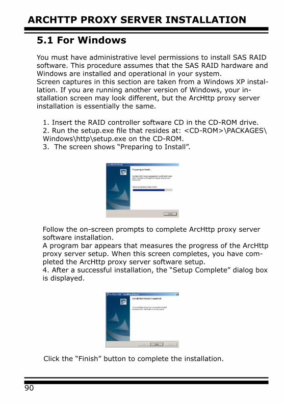
ARCHTTP PROXY SERVER INSTALLATION
90
5.1 For Windows
You must have administrative level permissions to install SAS RAID software. This procedure assumes that the SAS RAID hardware and Windows are installed and operational in your system.Screen captures in this section are taken from a Windows XP instal-lation. If you are running another version of Windows, your in-stallation screen may look different, but the ArcHttp proxy server installation is essentially the same.
1. Insert the RAID controller software CD in the CD-ROM drive.2. Run the setup.exe file that resides at: <CD-ROM>\PACKAGES\Windows\http\setup.exe on the CD-ROM. 3. The screen shows “Preparing to Install”.
Follow the on-screen prompts to complete ArcHttp proxy server software installation.A program bar appears that measures the progress of the ArcHttp proxy server setup. When this screen completes, you have com-pleted the ArcHttp proxy server software setup.4. After a successful installation, the “Setup Complete” dialog box is displayed.
Click the “Finish” button to complete the installation.
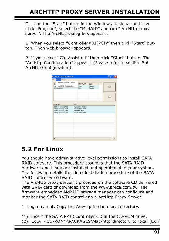
91
ARCHTTP PROXY SERVER INSTALLATION
Click on the “Start” button in the Windows task bar and then click “Program”, select the “McRAID” and run “ ArcHttp proxy server”. The ArcHttp dialog box appears.
1. When you select “Controller#01(PCI)” then click “Start” but-ton. Then web broswer appears.
2. If you select “Cfg Assistant” then click “Start” button. The “ArcHttp Configuration” appears. (Please refer to section 5.6 ArcHttp Configuration)
5.2 For LinuxYou should have administrative level permissions to install SATA RAID software. This procedure assumes that the SATA RAID hardware and Linux are installed and operational in your system.The following details the Linux installation procedure of the SATA RAID controller software. The ArcHttp proxy server is provided on the software CD delivered with SATA card or download from the www.areca.com.tw. The firmware embedded McRAID storage manager can configure and monitor the SATA RAID controller via ArcHttp Proxy Server.
1. Login as root. Copy the ArcHttp file to a local directory. (1). Insert the SATA RAID controller CD in the CD-ROM drive.(2). Copy <CD-ROM>\PACKAGES\Mac\http directory to local (Ex:/
ARCHTTP PROXY SERVER INSTALLATION
92
usr/local/sbin). Or(1). Download from the www.areca.com.tw or from the email attachment.
2. You must have administrative level permissions to install SATA RAID controller ArcHttp software. This procedure assumes that the SATA RAID hardware and driver are installed and operational in your system.
The following details are the installation procedure of the SATA RAID controller for Mac ArcHttp software.(1).Run the Archttp proxy server by using the following command:
Usage: ./archttp32 (TCP_PORT) or ./archttp64 (TCP_PORT). It depends on your OS version.
Parameters: TCP_PORT value= 1~65535 (If TCP_PORT assigned, Archttp will start from this port. Otherwise, it will use the setting in the archttpsrv.conf or default 81). This is the port address assigning for the first adapter.Such as: archttp64 1553
(2). Archttp server console started, Controller card detected then ArcHttp proxy server screen appears.
Copyright (c) 2004 Areca, Inc. All Rights Reserved.Areca HTTP proxy server V1.80.240 for Areca RAID controllers. Controller(s) list--------------------------------------------Controller[1](PCI) : Listen to port[1553].Cfg Assistant : Listen to port[1554].Binding IP:[0.0.0.0]Note: IP[0.0.0.0] stands for any ip bound to this host.--------------------------------------------##############################Press CTRL-C to exit program!!##############################Controller [1] Http: New client [9] acceptedController [1] Http: New Recv 243 bytesController [1] Http: Send [174] bytes back to the client
93
ARCHTTP PROXY SERVER INSTALLATION
5.3 For FreeBSD
You must have administrative level permissions to install SAS RAID software. This procedure assumes that the SAS RAID hardware and FreeBSD are installed and operational in your system.The following details the FreeBSD installation procedure of the SAS RAID controller software.
1. Insert the RAID controller software CD in the CD-ROM drive.2. Copy <CD-ROM>\PACKAGES\FreeBSD\http directory to local The next following step is the same with Linux. Please see section 5.2 For Linux.
5.4 For Solaris 10 X86
Please refer to the “readme.txt“ file on the software CD or website: http://www.areca.com.tw. The next step is the same with Linux. Please see section 5.2 For Linux.
5.5 For Mac OS 10.X The ArcHttp proxy server is provided on the software CD delivered with SATA card or download from the www.areca.com.tw. The firmware embedded McRAID storage manager can configure and monitor the SATA RAID controller via ArcHttp proxy server. The Archttp proxy server for Mac, please reference Chapter 4.6 Driver Installation for Mac 10.x or refer to the the Mac_manual_xxxx.pdf that resides at CD <CD-ROM>\DOCS directory. You can install driver, archttp64 and arc-cli from software CD < CD >\package\Mac OS directory at the same time.
(2). If you need the “Cfg Assistant”, please refer to section 5.6 ArcHttp Configuration.
3. See the next chapter detailing the McRAID Storage Manager to customize your RAID volume set.
For Mozilla user:
Because our management need Java support, so user may need upgrade to version 1.6 or later.
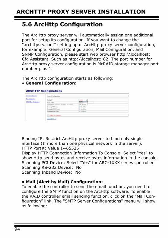
ARCHTTP PROXY SERVER INSTALLATION
94
5.6 ArcHttp Configuration
The ArcHttp proxy server will automatically assign one additional port for setup its configuration. If you want to change the "archttpsrv.conf" setting up of ArcHttp proxy server configuration, for example: General Configuration, Mail Configuration, and SNMP Configuration, please start web browser http:\\localhost: Cfg Assistant. Such as http:\\localhost: 82. The port number for ArcHttp proxy server configuration is McRAID storage manager port number plus 1.
The ArcHttp configuration starts as following:• General Configuration:
Binding IP: Restrict ArcHttp proxy server to bind only single interface (If more than one physical network in the server).HTTP Port#: Value 1~65535Display HTTP Connection Information To Console: Select “Yes" to show Http send bytes and receive bytes information in the console.Scanning PCI Device: Select “Yes” for ARC-1XXX series controllerScanning RS-232 Device: No Scanning Inband Device: No
• Mail (Alert by Mail) Configuration:To enable the controller to send the email function, you need to configure the SMTP function on the ArcHttp software. To enable the RAID controller email sending function, click on the “Mail Con-figuration” link. The "SMTP Server Configurations" menu will show as following:

95
ARCHTTP PROXY SERVER INSTALLATION
When you open the mail configuration page, you will see following settings:
SMTP Server Configuration:SMTP server IP Address: Enter the SMTP server IP address which is not MCRAID manager IP.Ex: 192.168.0.2
Mail Address Configurations:Sender Name: Enter the sender name that will be shown in the outgoing mail.Ex: RaidController_1Mail address: Enter the sender email that will be shown in the outgoing mail, but don’t type IP to replace domain name. Ex: [email protected]
Account: Enter the valid account if your SMTP mail server need authentication.
Password: Enter the valid password if your SMTP mail server need authentication.
MailTo Name: Enter the alert receiver name that will be shown in the outgoing mail.
Mail Address: Enter the alert receiver mail address Ex: [email protected]
Event Notification Configurations:According to your requirement, set the corresponding event level :
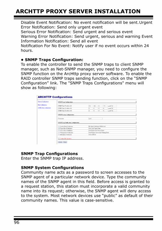
ARCHTTP PROXY SERVER INSTALLATION
96
Disable Event Notification: No event notification will be sent. Urgent Error Notification: Send only urgent eventSerious Error Notification: Send urgent and serious eventWarning Error Notification: Send urgent, serious and warning EventInformation Notification: Send all eventNotification For No Event: Notify user if no event occurs within 24 hours.
• SNMP Traps Configuration:To enable the controller to send the SNMP traps to client SNMP manager, such as Net-SNMP manager, you need to configure the SNMP function on the ArcHttp proxy server software. To enable the RAID controller SNMP traps sending function, click on the “SNMP Configuration” link. The "SNMP Traps Configurations" menu will show as following:
SNMP Trap Configurations Enter the SNMP trap IP address.
SNMP System Configurations Community name acts as a password to screen accesses to the SNMP agent of a particular network device. Type the community names of the SNMP agent in this field. Before access is granted to a request station, this station must incorporate a valid community name into its request; otherwise, the SNMP agent will deny access to the system. Most network devices use “public” as default of their community names. This value is case-sensitive.
97
ARCHTTP PROXY SERVER INSTALLATION
Note:
Event Notification Table refer to Appendix D.After you confirm and submit configurations, you can use "Generate Test Event" feature to make sure these settings are correct.
SNMP Trap Notification Configurations Before the client side manager application accepts the SAS RAID controller traps, it is necessary to integrate the MIB into the management application’s database of events and status indicator codes. This process is known as compiling the MIB into the application. This process is highly vendor-specific and should be well-covered in the User’s Guide of your SNMP application. Ensure the compilation process successfully integrates the contents of the ARECARAID.MIB file into the traps database.
WEB BROWSER-BASED CONFIGURATION
98
6. Web Browser-based Configuration Before using the firmware-based browser McRAID storage manager, do the initial setup and installation of this product. If you need to boot up the operating system from a RAID volume set, you must first create a RAID volume by using McBIOS RAID manager. Please refer to section 3.3 Using Quick Volume /Raid Setup Configuration for information on creating this initial volume set.
The McRAID storage manager is firmware-based utility, which is acces-sible via the web browser installed on your operating system.The web browser-based McRAID storage manager is a HTML-based application, which utilizes the browser (IE, Netscape and Mozilla etc) installed on your monitor station. It can be accessed through the In-Band PCIe bus or Out-of-Band LAN port. The In-Band method via archttp proxy server to launch the web browser-based McRAID storage manager. The firmware-embedded web browser-based McRAID storage manager allows local or remote to ac-cess it from any standard internet browser via a LAN or WAN with no software or patches required. The firmware contains SMTP manager monitors all system events and user can select either single or multiple user notifications to be sent via LAN with “Plain English” e-mails. The firmware-embedded SNMP agent allows remote to monitor events via LAN with no SNMP agent required.
• Create raid set• Expand raid set• Define volume set• Add physical drive • Modify volume set• Modify RAID level/stripe size• Define pass-through disk drives• Modify system function• Update firmware• Designate drives as hot spares
6.1 Start-up McRAID Storage Manager
With the McRAID storage manager, you can locally manage a system containing a SAS RAID controller that has Windows, Linux
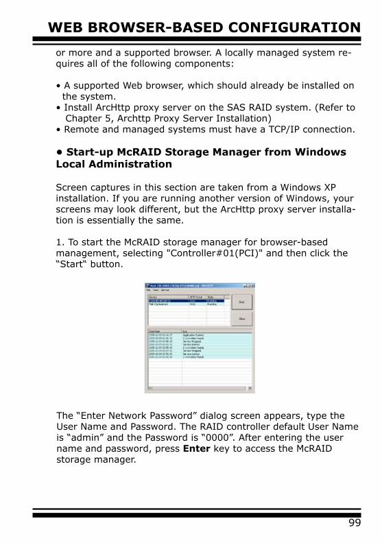
99
WEB BROWSER-BASED CONFIGURATION
or more and a supported browser. A locally managed system re-quires all of the following components:
• A supported Web browser, which should already be installed on the system.• Install ArcHttp proxy server on the SAS RAID system. (Refer to Chapter 5, Archttp Proxy Server Installation)• Remote and managed systems must have a TCP/IP connection.
• Start-up McRAID Storage Manager from Windows Local Administration
Screen captures in this section are taken from a Windows XP installation. If you are running another version of Windows, your screens may look different, but the ArcHttp proxy server installa-tion is essentially the same.
1. To start the McRAID storage manager for browser-based management, selecting "Controller#01(PCI)" and then click the “Start“ button.
The “Enter Network Password” dialog screen appears, type the User Name and Password. The RAID controller default User Name is “admin” and the Password is “0000”. After entering the user name and password, press Enter key to access the McRAID storage manager.
WEB BROWSER-BASED CONFIGURATION
100
• Start-up McRAID Storage Manager from Linux/FreeBSD/Solaris/Mac Local Administration
To configure the internal SAS RAID controller. You need to know its IP address. You can find the IP address assigned by the Archttp proxy server installation:Binding IP:[X.X.X.X] and controller listen port.
(1). Launch your McRAID storage manager by entering http://[Computer IP Address]:[Port Number] in the web browser.
(2). When connection is established, the "System Login" screen appears. The SAS RAID controller default User Name is “admin” and the Password is “0000”
• Start-up McRAID Storage Manager Through Ether-net Port (Out-of-Band)
Areca now offers an alternative means of communication for the PCIe RAID controller – Web browser-based McRAID storage man-ager program. User can access the built-in configuration without needing system starting up running the ArcHttp proxy sever. The web browser-based McRAID storage manager program is an HTML-based application, which utilizes the browser installed on your remote system.
To ensure proper communications between the PCIe RAID control-ler and web browser-based McRAID storage manager, Please con-nect the RAID controller LAN port to any LAN switch port.
The controller has embedded the TCP/IP & Web Browser-based RAID manager in the firmware. User can remote manage the RAID controller without adding any user specific software (plat-form independent) via standard web browsers directly connected

101
WEB BROWSER-BASED CONFIGURATION
to the 10/100 RJ45 LAN port.To configure RAID controller on a remote machine, you need to know its IP address. The IP address will default show in McBIOS RAID manager of “Ethernet Configuration” or “System Informa-tion” option. Launch your firmware-embedded TCP/IP & web browser-based McRAID storage manager by entering http://[IP Address] in the web browser.
6.2 SAS RAID controller McRAID Storage Manager
The McRAID storage manager initial start-up screen displays the current configuration of your SAS RAID controller. It displays the “Raid Set List”, “Volume Set List”, and “Physical Disk List”. The RAID set information, volume set information, and drive informa-tion can also be viewed by clicking on the “RAID Set Hierarchy” screen. The current configuration can also be viewed by clicking on “RAID Set Hierarchy” in the main menu.
Note:
You can find controller Ethernet port IP address in McBIOS RAID manager “System Information” option.
To display RAID set information, move the mouse cursor to the desired RAID set number, then click it. The RAID set information will appear. To display volume set information, move the mouse cursor to the desired volume set number, then click it. The volume set Information will display. To display drive information, move the mouse cursor to the desired physical drive number, then click it. The drive information will display.
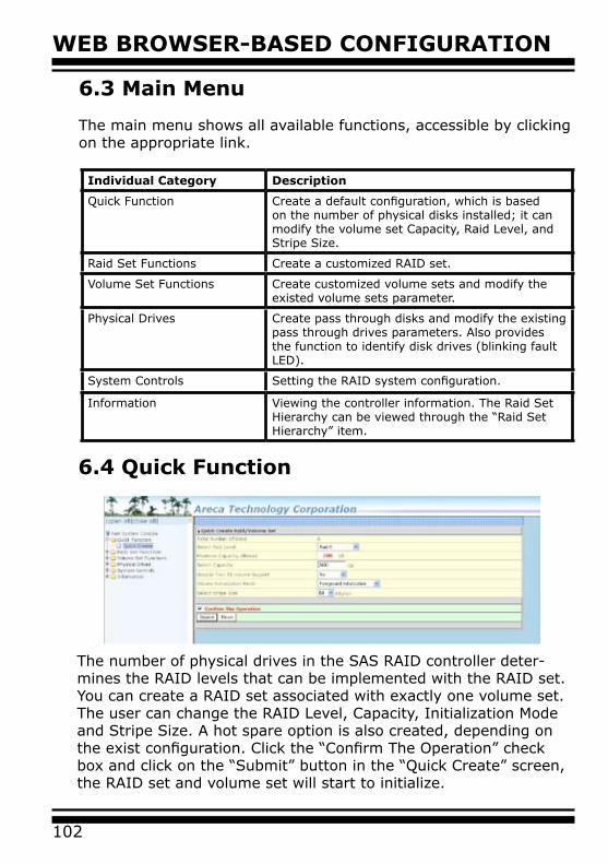
WEB BROWSER-BASED CONFIGURATION
102
6.3 Main Menu
The main menu shows all available functions, accessible by clicking on the appropriate link.
Individual Category Description
Quick Function Create a default configuration, which is based on the number of physical disks installed; it can modify the volume set Capacity, Raid Level, and Stripe Size.
Raid Set Functions Create a customized RAID set.
Volume Set Functions Create customized volume sets and modify the existed volume sets parameter.
Physical Drives Create pass through disks and modify the existing pass through drives parameters. Also provides the function to identify disk drives (blinking fault LED).
System Controls Setting the RAID system configuration.
Information Viewing the controller information. The Raid Set Hierarchy can be viewed through the “Raid Set Hierarchy” item.
6.4 Quick Function
The number of physical drives in the SAS RAID controller deter-mines the RAID levels that can be implemented with the RAID set. You can create a RAID set associated with exactly one volume set. The user can change the RAID Level, Capacity, Initialization Mode and Stripe Size. A hot spare option is also created, depending on the exist configuration. Click the “Confirm The Operation” check box and click on the “Submit” button in the “Quick Create” screen, the RAID set and volume set will start to initialize.
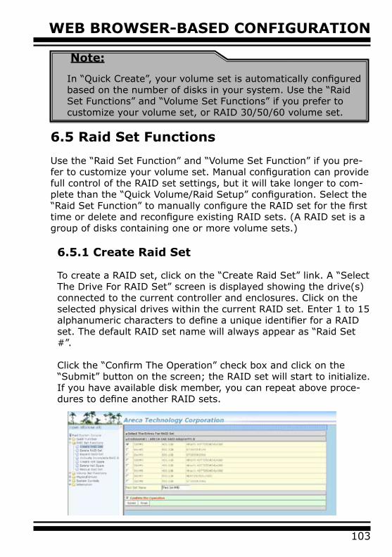
103
WEB BROWSER-BASED CONFIGURATION
Note:
In “Quick Create”, your volume set is automatically configured based on the number of disks in your system. Use the “Raid Set Functions” and “Volume Set Functions” if you prefer to customize your volume set, or RAID 30/50/60 volume set.
6.5 Raid Set Functions
Use the “Raid Set Function” and “Volume Set Function” if you pre-fer to customize your volume set. Manual configuration can provide full control of the RAID set settings, but it will take longer to com-plete than the “Quick Volume/Raid Setup” configuration. Select the “Raid Set Function” to manually configure the RAID set for the first time or delete and reconfigure existing RAID sets. (A RAID set is a group of disks containing one or more volume sets.)
6.5.1 Create Raid Set
To create a RAID set, click on the “Create Raid Set” link. A “Select The Drive For RAID Set” screen is displayed showing the drive(s) connected to the current controller and enclosures. Click on the selected physical drives within the current RAID set. Enter 1 to 15 alphanumeric characters to define a unique identifier for a RAID set. The default RAID set name will always appear as “Raid Set #”. Click the “Confirm The Operation” check box and click on the “Submit” button on the screen; the RAID set will start to initialize. If you have available disk member, you can repeat above proce-dures to define another RAID sets.

WEB BROWSER-BASED CONFIGURATION
104
Note:
To create RAID 30/50/60 volume, you need create multiple RAID sets first with the same disk members on each RAID set. The max no. disk drives per volume set: 8
6.5.2 Delete Raid Set
To delete a RAID set, click on the “Deleted Raid Set” link. A “Select The RAID Set To Delete” screen is displayed showing all exist RAID sets in the current controller. Click the RAID set num-ber which you want to delete in the select column on the delete screen. Then, click the “Confirm The Operation” check box and click on the “Submit” button in the screen to delete it. The volume sets included in the “Delete RAID Set”. It will be deleted by this action. But for the Raid 30/50/60, you need to delete the volume belonging to those RAID sets.
6.5.3 Expand Raid Set
Instead of deleting a RAID set and recreating it with additional disk drives, the “Expand Raid Set” function allows the users to add disk drives to the RAID set that have already been created.To expand a RAID set:Select the “Expand Raid Set” option. If there is an available disk, then the “Select SATA Drives For Raid Set Expansion” screen appears.Select the target RAID set by clicking on the appropriate radio button. Select the target disk by clicking on the appropriate check box.
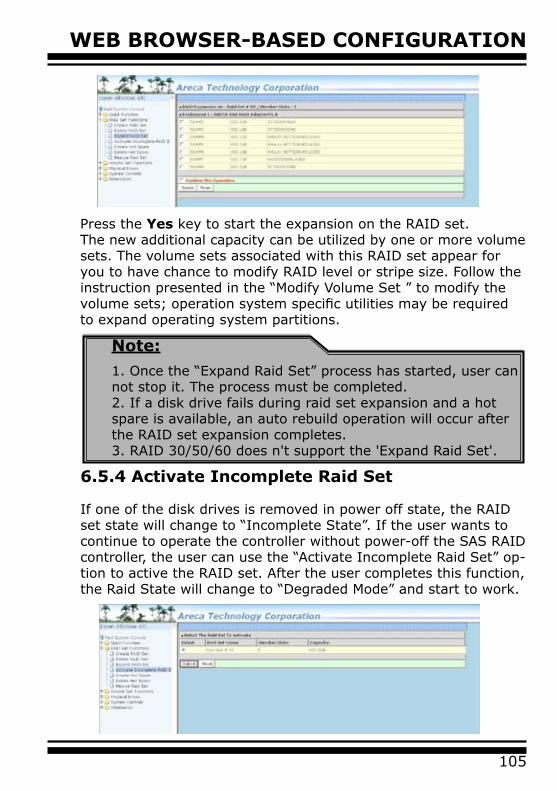
105
WEB BROWSER-BASED CONFIGURATION
Press the Yes key to start the expansion on the RAID set.The new additional capacity can be utilized by one or more volume sets. The volume sets associated with this RAID set appear for you to have chance to modify RAID level or stripe size. Follow the instruction presented in the “Modify Volume Set ” to modify the volume sets; operation system specific utilities may be required to expand operating system partitions.
6.5.4 Activate Incomplete Raid Set
If one of the disk drives is removed in power off state, the RAID set state will change to “Incomplete State”. If the user wants to continue to operate the controller without power-off the SAS RAID controller, the user can use the “Activate Incomplete Raid Set” op-tion to active the RAID set. After the user completes this function, the Raid State will change to “Degraded Mode” and start to work.
Note:
1. Once the “Expand Raid Set” process has started, user can not stop it. The process must be completed.2. If a disk drive fails during raid set expansion and a hot spare is available, an auto rebuild operation will occur after the RAID set expansion completes.3. RAID 30/50/60 does n't support the 'Expand Raid Set'.
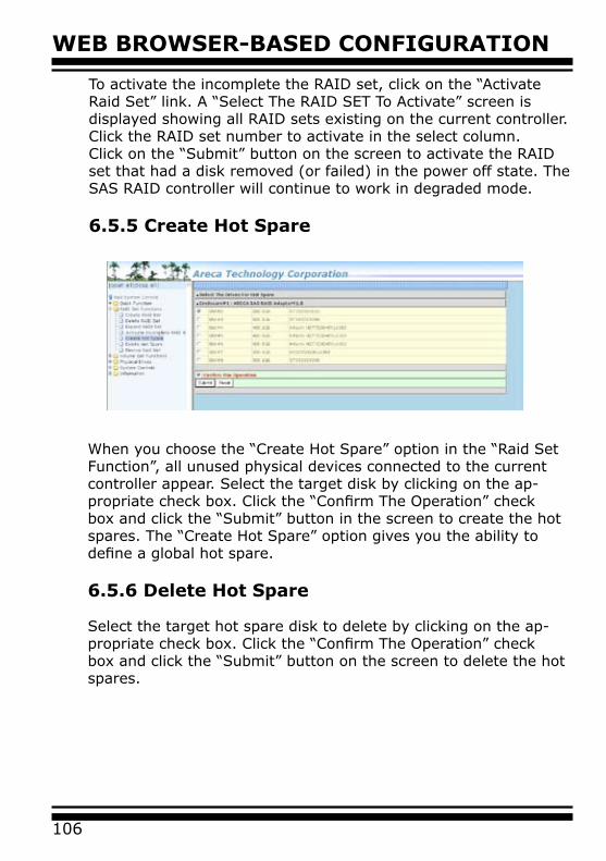
WEB BROWSER-BASED CONFIGURATION
106
To activate the incomplete the RAID set, click on the “Activate Raid Set” link. A “Select The RAID SET To Activate” screen is displayed showing all RAID sets existing on the current controller. Click the RAID set number to activate in the select column. Click on the “Submit” button on the screen to activate the RAID set that had a disk removed (or failed) in the power off state. The SAS RAID controller will continue to work in degraded mode.
6.5.5 Create Hot Spare
When you choose the “Create Hot Spare” option in the “Raid Set Function”, all unused physical devices connected to the current controller appear. Select the target disk by clicking on the ap-propriate check box. Click the “Confirm The Operation” check box and click the “Submit” button in the screen to create the hot spares. The “Create Hot Spare” option gives you the ability to define a global hot spare.
6.5.6 Delete Hot Spare
Select the target hot spare disk to delete by clicking on the ap-propriate check box. Click the “Confirm The Operation” check box and click the “Submit” button on the screen to delete the hot spares.

107
WEB BROWSER-BASED CONFIGURATION
6.5.7 Rescue Raid Set
When the system is powered off in the RAID set update/creation period, the configuration possibly could disappear due to this ab-normal condition. The “RESCUE” function can recover the missing RAID set information. The RAID controller uses the time as the RAID set signature. The RAID set may have different time after the RAID set is recovered. The “SIGANT” function can regenerate the signature for the RAID set.
6.5.8 Offline Raid Set
This function is for customer being able to unmount and remount a multi-disk volume. All Hdds of the selected RAID set will be put into offline state, spun down and fault LED in fast blinking mode.User can remove those Hdds and insert new Hdds on those empty slots without needing power down the controller.
6.6 Volume Set Functions
A volume set is seen by the host system as a single logical device. It is organized in a RAID level with one or more physical disks. RAID level refers to the level of data performance and protection of a volume set. A volume set capacity can consume all or a portion
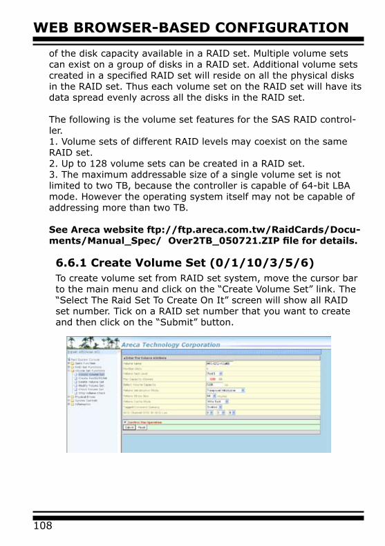
WEB BROWSER-BASED CONFIGURATION
108
of the disk capacity available in a RAID set. Multiple volume sets can exist on a group of disks in a RAID set. Additional volume sets created in a specified RAID set will reside on all the physical disks in the RAID set. Thus each volume set on the RAID set will have its data spread evenly across all the disks in the RAID set.
The following is the volume set features for the SAS RAID control-ler.1. Volume sets of different RAID levels may coexist on the same RAID set.2. Up to 128 volume sets can be created in a RAID set.3. The maximum addressable size of a single volume set is not limited to two TB, because the controller is capable of 64-bit LBA mode. However the operating system itself may not be capable of addressing more than two TB.
See Areca website ftp://ftp.areca.com.tw/RaidCards/Docu-ments/Manual_Spec/ Over2TB_050721.ZIP file for details. 6.6.1 Create Volume Set (0/1/10/3/5/6) To create volume set from RAID set system, move the cursor bar to the main menu and click on the “Create Volume Set” link. The “Select The Raid Set To Create On It” screen will show all RAID set number. Tick on a RAID set number that you want to create and then click on the “Submit” button.
109
WEB BROWSER-BASED CONFIGURATION
The new create volume set attribute allows user to select the Volume Name, RAID Level, Capacity, Greater Two TB Volume Support, Initialization Mode, Strip Size, Cache Mode, Tagged Command Queuing, SCSI Channel/SCSI ID/SCSI Lun.
• Volume NameThe default volume name will always appear as “ARC-1212-VOL”. You can rename the volume set providing it does not exceed the 15 characters limit.
• Volume Raid Level Set the RAID level for the volume set. Highlight the desired RAID Level and press Enter key. The available RAID levels for the current volume set are displayed. Select a RAID level and press Enter key to confirm.
• CapacityThe maximum volume size is the default initial setting. Enter the appropriate volume size to fit your application.
• Greater Two TB Volume SupportIf volume capacity will exceed Two TB, controller will show the "Greater Two TB Volume Support" sub-menu. Greater Two TB Volume Support option: No and 64bit LBA.For more details please download PDF file from ftp://ftp.areca.com.tw/RaidCards/Documents/Manual_Spec/Over2TB_050721.zip
• Initialization ModePress Enter key to define “Background Initialization”, “Fore-ground Initialization” or “No Init (To Rescue Volume)”. When “Background Initialization”, the initialization proceeds as a background task, the volume set is fully accessible for system reads and writes. The operating system can instantly access to the newly created arrays without requiring a reboot and waiting the initialization complete. When “Foreground Initialization”, the initialization proceeds must be completed before the volume set ready for system accesses. There is no initialization happed when you select “No Init” option. “No Init“ is for customer to rescue volume without losing data in the disk.
WEB BROWSER-BASED CONFIGURATION
110
• Strip SizeThis parameter sets the size of the stripe written to each disk in a RAID 0, 1, 10, 5, 6, 50 or 60 logical drive. You can set the stripe size to 4 KB, 8 KB, 16 KB, 32 KB, 64 KB, or 128 KB.A larger stripe size produces better read performance, espe-cially if your computer does mostly sequential reads. However, if you are sure that your computer does random reads more often, select a smaller stripe size.
Note:
RAID level 3 can’t modify the cache strip size.
• Cache ModeThe SAS RAID controller supports “Write Through” and “Write Back” cache.
• Tagged Command Queuing
The “Enabled” option is useful for enhancing overall system performance under multi-tasking operating systems. The Command Tag (Drive Channel) function controls the SAS command tag queuing support for each drive channel. This function should normally remain “Enabled”. “Disabled” this function only when using SAS drives that do not support command tag queuing.
• SCSI Channel/SCSI ID/SCSI LunSCSI Channel: The SAS RAID controller function is simulated as a external SCSI RAID controller. The host bus is represented as a SCSI channel. Choose the SCSI Channel. SCSI ID: Each SCSI device attached to the SCSI card, as well as the card itself, must be assigned a unique SCSI ID number. A SCSI channel can connect up to 15 devices. The SAS RAID controller is a large SCSI device. Assign an ID from a list of SCSI IDs. SCSI LUN: Each SCSI ID can support up to 8 LUNs. Most SAS controllers treat each LUN like a SAS disk.
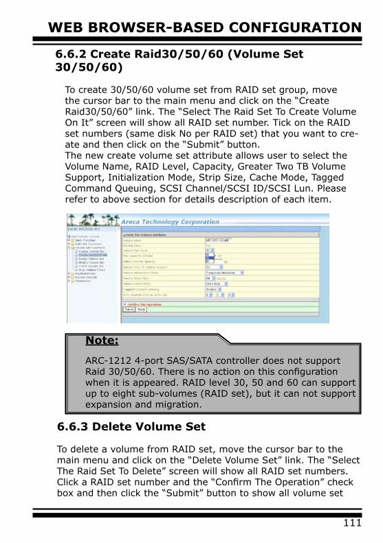
111
WEB BROWSER-BASED CONFIGURATION
6.6.2 Create Raid30/50/60 (Volume Set 30/50/60)
To create 30/50/60 volume set from RAID set group, move the cursor bar to the main menu and click on the “Create Raid30/50/60” link. The “Select The Raid Set To Create Volume On It” screen will show all RAID set number. Tick on the RAID set numbers (same disk No per RAID set) that you want to cre-ate and then click on the “Submit” button.The new create volume set attribute allows user to select the Volume Name, RAID Level, Capacity, Greater Two TB Volume Support, Initialization Mode, Strip Size, Cache Mode, Tagged Command Queuing, SCSI Channel/SCSI ID/SCSI Lun. Please refer to above section for details description of each item.
Note:
ARC-1212 4-port SAS/SATA controller does not support Raid 30/50/60. There is no action on this configuration when it is appeared. RAID level 30, 50 and 60 can support up to eight sub-volumes (RAID set), but it can not support expansion and migration.
6.6.3 Delete Volume Set
To delete a volume from RAID set, move the cursor bar to the main menu and click on the “Delete Volume Set” link. The “Select The Raid Set To Delete” screen will show all RAID set numbers. Click a RAID set number and the “Confirm The Operation” check box and then click the “Submit” button to show all volume set
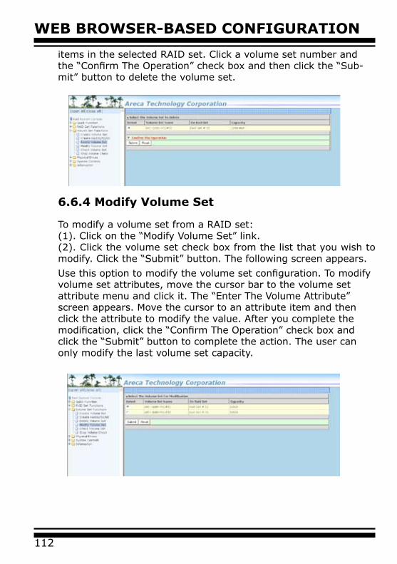
WEB BROWSER-BASED CONFIGURATION
112
items in the selected RAID set. Click a volume set number and the “Confirm The Operation” check box and then click the “Sub-mit” button to delete the volume set.
6.6.4 Modify Volume Set
To modify a volume set from a RAID set:(1). Click on the “Modify Volume Set” link.(2). Click the volume set check box from the list that you wish to modify. Click the “Submit” button. The following screen appears.
Use this option to modify the volume set configuration. To modify volume set attributes, move the cursor bar to the volume set attribute menu and click it. The “Enter The Volume Attribute” screen appears. Move the cursor to an attribute item and then click the attribute to modify the value. After you complete the modification, click the “Confirm The Operation” check box and click the “Submit” button to complete the action. The user can only modify the last volume set capacity.
113
WEB BROWSER-BASED CONFIGURATION
6.6.4.1 Volume Growth
Use “Expand RAID Set’ function to add disk to a RAID set. The additional capacity can be used to enlarge the last volume set size or to create another volume set. The “Modify Volume Set” function can support the “Volume Modification” function. To expand the last volume set capacity , move the cursor bar to the “ Capacity” item and entry the capacity size. When finished the above action, press the ESC key and select the Yes option to complete the action. The last volume set starts to expand its capacity.
To expand an existing volume noticed:
• Only the last volume can expand capacity.• When expand volume capacity, you can’t modify stripe size or modify RAID revel simultaneously.• You can expand volume capacity, but can’t reduce volume capacity size. • After volume expansion, the volume capacity can't be decreased.
For greater 2TB expansion:
• If your system installed in the volume, don't expand the volume capacity greater 2TB, currently OS can’t support boot up from a greater 2TB capacity device.• Expand over 2TB used LBA64 mode. Please make sure your OS supports LBA64 before expand it.
6.6.4.2 Volume Set Migration
Migrating occurs when a volume set is migrating from one RAID level to another, when a volume set strip size changes, or when a disk is added to a RAID set. Migration state is displayed in the volume state area of the “Volume Set Information” screen.
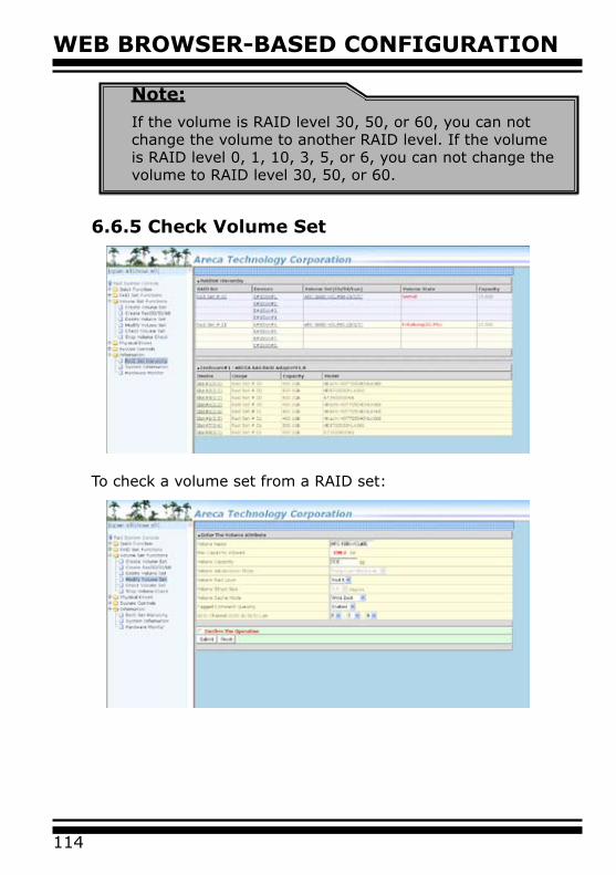
WEB BROWSER-BASED CONFIGURATION
114
Note:
If the volume is RAID level 30, 50, or 60, you can not change the volume to another RAID level. If the volume is RAID level 0, 1, 10, 3, 5, or 6, you can not change the volume to RAID level 30, 50, or 60.
6.6.5 Check Volume Set
To check a volume set from a RAID set:

115
WEB BROWSER-BASED CONFIGURATION
(1). Click on the “Check Volume Set” link.(2). Click on the volume set from the list that you wish to check. Tick on “Confirm The Operation” and click on the “Submit” button.Use this option to verify the correctness of the redundant data in a volume set. For example, in a system with dedicated parity, vol-ume set check means computing the parity of the data disk drives and comparing the results to the contents of the dedicated parity disk drive. The checking percentage can also be viewed by click-ing on “RAID Set Hierarchy” in the main menu.
6.6.6 Stop Volume Set Check Use this option to stop the “Check Volume Set” function.
6.7 Physical Drive
Choose this option to select a physical disk from the main menu and then perform the operations listed below.
6.7.1 Create Pass-Through Disk
To create pass-through disk, move the mouse cursor to the main menu and click on the “Create Pass-Through” link. The “relative setting function” screen appears. A pass-through disk is not con-trolled by the SAS RAID controller firmware, it cann’t be a part of a volume set. The disk is available to the operating system as an individual disk. It is typically used on a system where the operat-ing system is on a disk not controlled by the RAID firmware. The user can also select the Cache Mode, Tagged Command Queuing, SCSI channel/SCSI_ID/SCSI_LUN for this pass-through disk.
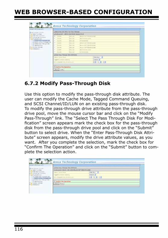
WEB BROWSER-BASED CONFIGURATION
116
6.7.2 Modify Pass-Through Disk
Use this option to modify the pass-through disk attribute. The user can modify the Cache Mode, Tagged Command Queuing, and SCSI Channel/ID/LUN on an existing pass-through disk.To modify the pass-through drive attribute from the pass-through drive pool, move the mouse cursor bar and click on the “Modify Pass-Through” link. The “Select The Pass Through Disk For Modi-fication” screen appears mark the check box for the pass-through disk from the pass-through drive pool and click on the “Submit” button to select drive. When the “Enter Pass-Through Disk Attri-bute” screen appears, modify the drive attribute values, as you want. After you complete the selection, mark the check box for “Confirm The Operation” and click on the “Submit” button to com-plete the selection action.

117
WEB BROWSER-BASED CONFIGURATION
6.7.3 Delete Pass-Through Disk
To delete a pass-through drive from the pass-through drive pool, move the mouse cursor bar to the main menus and click the “De-lete Pass Through” link. After you complete the selection, mark the check box for “Confirm The Operation” and click the “Submit” button to complete the delete action.
6.7.4 Identify Drive
To prevent removing the wrong drive, the selected disk faultLED indicator will light for physically locating the selected diskwhen the “Identify Selected Device” is selected.
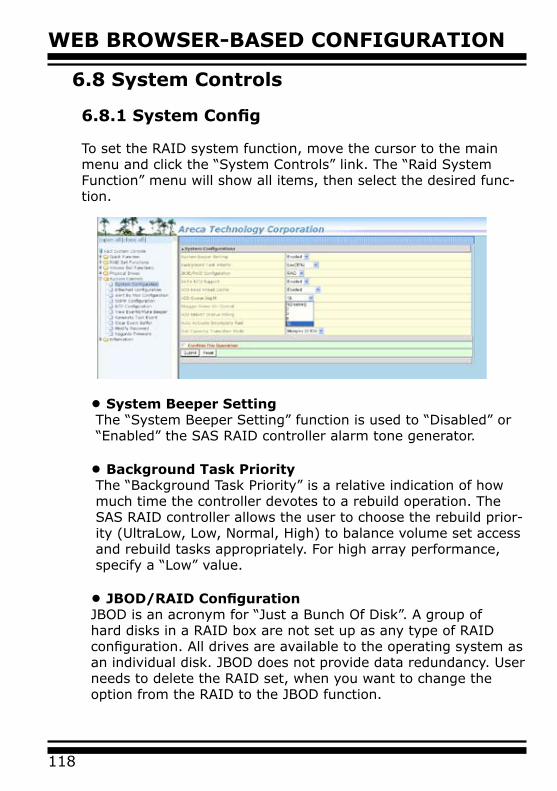
WEB BROWSER-BASED CONFIGURATION
118
6.8 System Controls
6.8.1 System Config
To set the RAID system function, move the cursor to the main menu and click the “System Controls” link. The “Raid System Function” menu will show all items, then select the desired func-tion.
• System Beeper SettingThe “System Beeper Setting” function is used to “Disabled” or “Enabled” the SAS RAID controller alarm tone generator.
• Background Task PriorityThe “Background Task Priority” is a relative indication of how much time the controller devotes to a rebuild operation. The SAS RAID controller allows the user to choose the rebuild prior-ity (UltraLow, Low, Normal, High) to balance volume set access and rebuild tasks appropriately. For high array performance, specify a “Low” value.
• JBOD/RAID ConfigurationJBOD is an acronym for “Just a Bunch Of Disk”. A group of hard disks in a RAID box are not set up as any type of RAID configuration. All drives are available to the operating system as an individual disk. JBOD does not provide data redundancy. User needs to delete the RAID set, when you want to change the option from the RAID to the JBOD function.
119
WEB BROWSER-BASED CONFIGURATION
• HDD Read Ahead CacheAllow Read Ahead (Default: Enabled)—When Enabled, the drive’s read ahead cache algorithm is used, providing maximum performance under most circumstances.
• HDD Queue Depth
This parameter is adjusted the queue depth capacity of NCQ (SATA HDD) or Tagged Command Queuing (SAS) which trans-mits multiple commands to a single target without waiting for the initial command to complete.
• Stagger Power on In a PC system with only one or two drives, the power cansupply enough power to spin up both drives simultaneously. Butin systems with more than two drives, the startup current fromspinning up the drives all at once can overload the power sup-ply, causing damage to the power supply, disk drives and othersystem components. This damage can be avoided by allowingthe host to stagger the spin-up of the drives. The SAS/SATA drives have support stagger spin-up capabilities to boost reli-ability. Stagger spin-up is a very useful feature for managing multiple disk drives in a storage subsystem. It gives the host the ability to spin up the disk drives sequentially or in groups, allowing the drives to come ready at the optimum time without straining the system power supply. Staggering drive spin-up in a multiple drive environment also avoids the extra cost of a power supply designed to meet short-term startup power de-mand as well as steady state conditions. Areca RAID controller has included the option for customerto select the disk drives sequentially stagger power up value.The values can be selected from 0.4s to 6s per step which powers up one drive.
• Auto Activate Incomplete RaidWhen some of the disk drives are removed in power off state or boot up stage, the RAID set state will change to “Incomplete State”. But if a user wants to automatically continue to work while the SAS RAID controller is powered on, the user can set the “Auto Activate Incomplete Raid” option to enable. The RAID state will change to “Degraded Mode” while it powers on.
WEB BROWSER-BASED CONFIGURATION
120
• Disk Capacity Truncation Mode
Areca RAID controllers use drive truncation so that drives from differing vendors are more likely to be able to be used as spares for each other. Drive truncation slightly decreases the usable capacity of a drive that is used in redundant units.The controller provides three truncation modes in the system configuration: Multiples Of 10G, Multiples Of 1G, and Dis-abled. Multiples Of 10G: If you have 120 GB drives from differ-ent vendors; chances are that the capacity varies slightly. For example, one drive might be 123.5 GB, and the other 120 GB. Multiples Of 10G truncates the number under tens. This makes same capacity for both of these drives so that one could replace the other.Multiples Of 1G: If you have 123 GB drives from different ven-dors; chances are that the capacity varies slightly. For example, one drive might be 123.5 GB, and the other 123.4 GB. Multiples Of 1G truncates the fractional part. This makes capacity for both of these drives so that one could replace the other. No Truncation: It does not truncate the capacity.
6.8.2 Ethernet Configuration
Use this feature to set the controller Ethernet port configuration. A customer doesn’t need to create a reserved space on the arrays before the Ethernet port and HTTP service are working. The firm-ware-embedded Web Browser-based RAID manager can access it from any standard internet browser or from any host computer either directly connected or via a LAN or WAN with no software or patches required.
DHCP (Dynamic Host Configuration Protocol) is a protocol that lets network administrators manage centrally and automate the assignment of IP (Internet Protocol) configurations on a computer network. When using the internet’s set of protocols (TCP/IP), in order for a computer system to communicate to another com-puter system, it needs a unique IP address. Without DHCP, the IP address must be entered manually at each computer system. DHCP lets a network administrator supervise and distribute IP addresses from a central point. The purpose of DHCP is to provide the automatic (dynamic) allocation of IP client configurations for
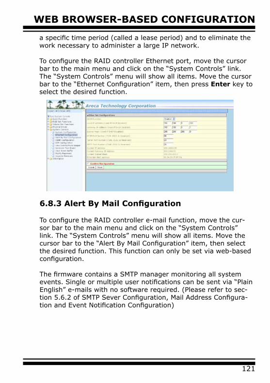
121
WEB BROWSER-BASED CONFIGURATION
a specific time period (called a lease period) and to eliminate the work necessary to administer a large IP network.
To configure the RAID controller Ethernet port, move the cursor bar to the main menu and click on the “System Controls” link. The “System Controls” menu will show all items. Move the cursor bar to the “Ethernet Configuration” item, then press Enter key to select the desired function.
6.8.3 Alert By Mail Configuration
To configure the RAID controller e-mail function, move the cur-sor bar to the main menu and click on the “System Controls” link. The “System Controls” menu will show all items. Move the cursor bar to the “Alert By Mail Configuration” item, then select the desired function. This function can only be set via web-based configuration.
The firmware contains a SMTP manager monitoring all system events. Single or multiple user notifications can be sent via “Plain English” e-mails with no software required. (Please refer to sec-tion 5.6.2 of SMTP Sever Configuration, Mail Address Configura-tion and Event Notification Configuration)
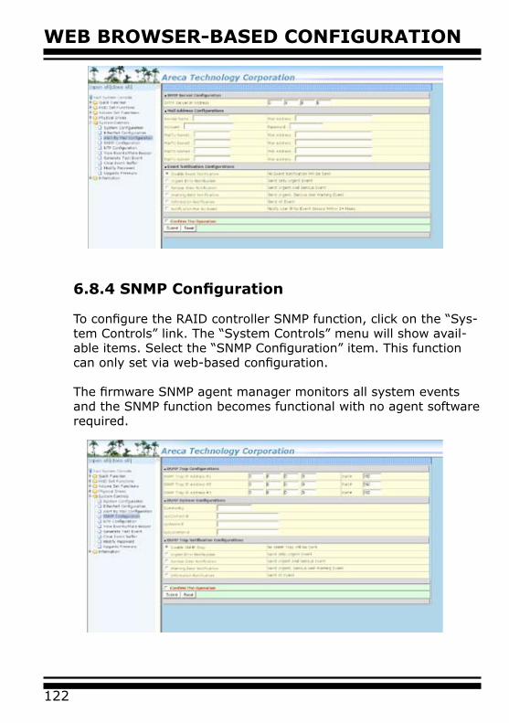
WEB BROWSER-BASED CONFIGURATION
122
6.8.4 SNMP Configuration To configure the RAID controller SNMP function, click on the “Sys-tem Controls” link. The “System Controls” menu will show avail-able items. Select the “SNMP Configuration” item. This function can only set via web-based configuration.
The firmware SNMP agent manager monitors all system events and the SNMP function becomes functional with no agent software required.
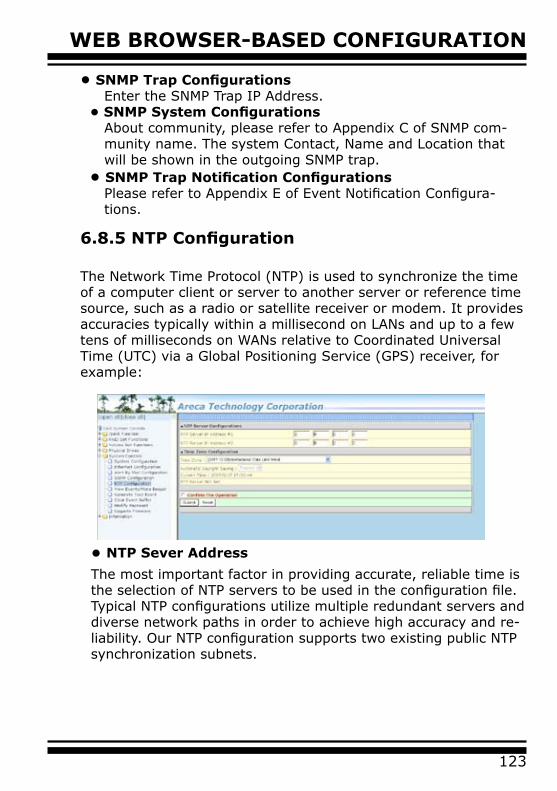
123
WEB BROWSER-BASED CONFIGURATION
• SNMP Trap ConfigurationsEnter the SNMP Trap IP Address.
• SNMP System ConfigurationsAbout community, please refer to Appendix C of SNMP com-munity name. The system Contact, Name and Location that will be shown in the outgoing SNMP trap.
• SNMP Trap Notification ConfigurationsPlease refer to Appendix E of Event Notification Configura-tions.
6.8.5 NTP Configuration The Network Time Protocol (NTP) is used to synchronize the time of a computer client or server to another server or reference time source, such as a radio or satellite receiver or modem. It provides accuracies typically within a millisecond on LANs and up to a few tens of milliseconds on WANs relative to Coordinated Universal Time (UTC) via a Global Positioning Service (GPS) receiver, for example:
• NTP Sever Address
The most important factor in providing accurate, reliable time is the selection of NTP servers to be used in the configuration file. Typical NTP configurations utilize multiple redundant servers and diverse network paths in order to achieve high accuracy and re-liability. Our NTP configuration supports two existing public NTP synchronization subnets.

WEB BROWSER-BASED CONFIGURATION
124
• Time Zone
Time Zone conveniently runs in the system tray and allows you to easily view the date and time in various locations around the world. You can also quickly and easily add your own personal locations to customize time zone the way you want.
• Automatic Daylight Saving
Automatic Daylight Saving will normally attempt to automati-cally adjust the system clock for daylight saving changes based on the computer time zone. This tweak allows you to disable the automatic adjustment.
6.8.6 View Events/Mute Beeper
To view the SAS RAID controller’s event information, click on the “View Event/Mute Beeper” link. The SAS RAID controller “System events Information” screen appears. The mute beeper function automatically enable by clicking on “View Events/Mute Beeper”.
Note:
NTP feature works through onboard Ethernet port. So you must make sure that you have connected onboard Ethernet port.
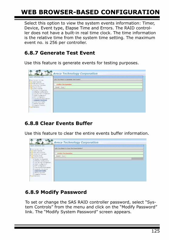
125
WEB BROWSER-BASED CONFIGURATION
Select this option to view the system events information: Timer, Device, Event type, Elapse Time and Errors. The RAID control-ler does not have a built-in real time clock. The time information is the relative time from the system time setting. The maximum event no. is 256 per controller.
6.8.7 Generate Test Event
Use this feature is generate events for testing purposes.
6.8.8 Clear Events Buffer
Use this feature to clear the entire events buffer information.
6.8.9 Modify Password
To set or change the SAS RAID controller password, select “Sys-tem Controls” from the menu and click on the “Modify Password” link. The “Modify System Password” screen appears.
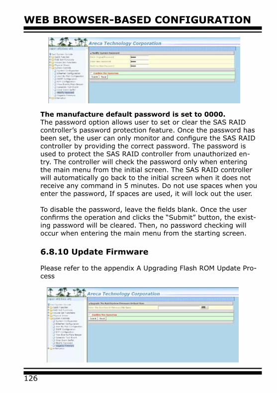
WEB BROWSER-BASED CONFIGURATION
126
The manufacture default password is set to 0000. The password option allows user to set or clear the SAS RAID controller’s password protection feature. Once the password has been set, the user can only monitor and configure the SAS RAID controller by providing the correct password. The password is used to protect the SAS RAID controller from unauthorized en-try. The controller will check the password only when entering the main menu from the initial screen. The SAS RAID controller will automatically go back to the initial screen when it does not receive any command in 5 minutes. Do not use spaces when you enter the password, If spaces are used, it will lock out the user. To disable the password, leave the fields blank. Once the user confirms the operation and clicks the “Submit” button, the exist-ing password will be cleared. Then, no password checking will occur when entering the main menu from the starting screen.
6.8.10 Update Firmware
Please refer to the appendix A Upgrading Flash ROM Update Pro-cess

127
WEB BROWSER-BASED CONFIGURATION
6.9 Information
6.9.1 Raid Set Hierarchy
Use this feature to view the SAS RAID controller current RAID set, current volume set and physical disk information. The volume state and capacity are also shown in this screen.
6.9.2 System Information
To view the SAS RAID controller’s system information, move the mouse cursor to the main menu and click on the “System Infor-mation” link. The SAS RAID controller “RAID Subsystem Informa-tion” screen appears.
Use this feature to view the SAS RAID controller’s system infor-mation. The controller name, controller firmware version, Boot ROM version, SAS firmware version, serial number, main proces-sor, CPU data/instruction cache size, system memory size/speed and current IP address appear in this screen.
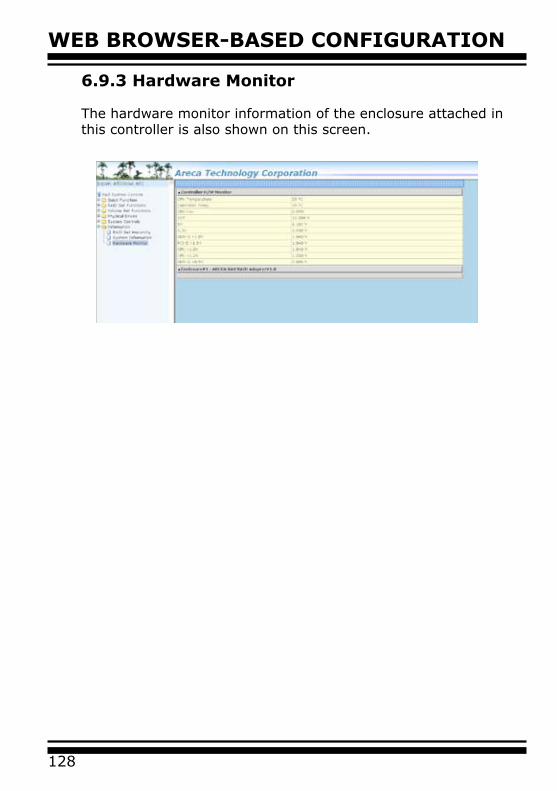
WEB BROWSER-BASED CONFIGURATION
128
6.9.3 Hardware Monitor
The hardware monitor information of the enclosure attached in this controller is also shown on this screen.
129
APPENDIX
Appendix A
Upgrading Flash ROM Update Process
Since the PCIe SAS RAID controller features flash ROM firmware, it is not necessary to change the hardware flash chip in order to upgrade the RAID firmware. The user can simply re-program the old firmware through the In-Band PCIe bus or Out-of-Band Eth-ernet port McRAID Storage manager and nflash DOS utility. New releases of the firmware are available in the form of a DOS file on the shipped CD or Areca website. The files available at the FTP site for each model contain the following files in each version:
ARC1212NNNN.BIN Software Binary Code ( “NNNN” refers to the software code type)
ARC1212BIOS.BIN :→ PCI card BIOS for system board usingARC1212BOOT.BIN :→ RAID controller hardware initializationARC1212FIRM.BIN :→ RAID kernel programARC1212MBR0.BIN:→ Master Boot Record for supporting Dual Flash Image in the SAS RAID controllerARC1212transport.BIN: → Intel IOP 348 SAS controller transport layer microcodeREADME.TXT contains the history information of the software code change in the main directory. Read this file first to make sure you are upgrading to the proper binary file. Select the right file for the upgrade. Normally, user upgrades the ARC1212BIOS.BIN for sys-tem M/B compatibility and ARC1212FIRM.BIN for RAID function upgrades.
Note:
Please update all Binary Code (BIOS, BOOT and FIRM) before you reboot system. Otherwise, a mixed firmware package may hang the controller.
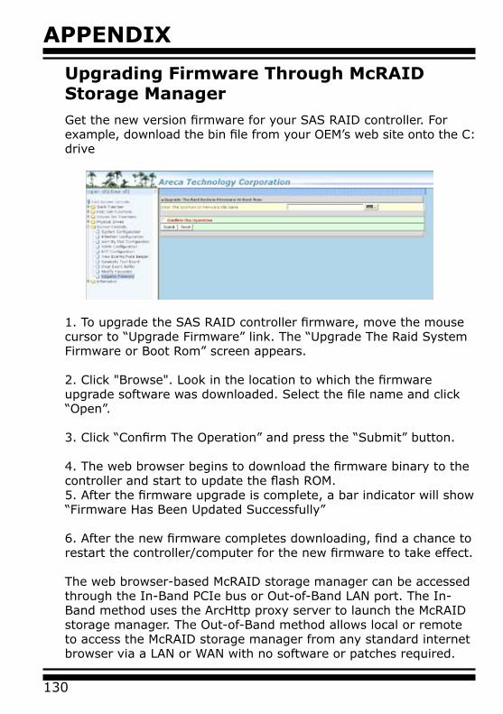
APPENDIX
130
Upgrading Firmware Through McRAID Storage ManagerGet the new version firmware for your SAS RAID controller. For example, download the bin file from your OEM’s web site onto the C: drive
1. To upgrade the SAS RAID controller firmware, move the mouse cursor to “Upgrade Firmware” link. The “Upgrade The Raid System Firmware or Boot Rom” screen appears.
2. Click "Browse". Look in the location to which the firmware upgrade software was downloaded. Select the file name and click “Open”.
3. Click “Confirm The Operation” and press the “Submit” button.
4. The web browser begins to download the firmware binary to the controller and start to update the flash ROM.5. After the firmware upgrade is complete, a bar indicator will show “Firmware Has Been Updated Successfully”
6. After the new firmware completes downloading, find a chance to restart the controller/computer for the new firmware to take effect.
The web browser-based McRAID storage manager can be accessed through the In-Band PCIe bus or Out-of-Band LAN port. The In-Band method uses the ArcHttp proxy server to launch the McRAID storage manager. The Out-of-Band method allows local or remote to access the McRAID storage manager from any standard internet browser via a LAN or WAN with no software or patches required.
131
APPENDIXController with onboard LAN port, you can directly plug an Ethernet cable to the controller LAN port, then enter the McBIOS RAID manager to configure the network setting. After network setting configured and saved, you can find the current IP address in the McBIOS RAID manager "System Information" page.
From a remote pc, you can directly open a web browser and enter the IP address. Then enter user name and password to login and start your management. You can find the firmware update feature from the "Raid system Console" on the "System Controls" option.
Upgrading Firmware Through nflash DOS Utility
Areca now offers an alternative means communication for the SAS RAID controller – Upgrade the all files (BIOS, BOOT, FIRM, MBR0 and Transport) without necessary system starting up to running the ArcHttp proxy server. The nflash utility program is a DOS application, which runs in the DOS operating system. Be sure of ensuring properly to communicate between SAS RAID controller and nflash DOS utility. Please make a bootable DOS floppy diskette or UBS devices from other Windows operating system and boot up the system from those bootable devices. • Starting the nflash UtilityYou do not need to short any jumper cap on running nflash utility. The nflash utility provides an on-line table of contents, brief descriptions of the help sub-commands. The nflash utility put on the <CD-ROM>\Firmware directory. You can run the <nflash> to get more detailed information about the command usage.Typical output looks as below:

APPENDIX
132
A:\nflashRaid Controller Flash UtilityV1.11 2007-11-8Command Usage:NFLASH FileNameNFLASH FileName /cn --> n=0,1,2,3 write binary to controller#0FileName May Be ARC1680FIRM.BIN or ARC1680*For ARC1212* Will Expand To ARC1212BOOT /FIRM/BIOS.BIN
A:\>nflash arc1212~1.binRaid Controller Flash UtilityV1.11 2007-11-8NODEL : ARC-1212MEM FE620000 FE7FF000File ARC121~1.BIN : >>*** => Flash 0K
Upgrading Firmware Through CLI
This Command Line Interface (CLI) provides you to configure and manage the Areca SAS RAID controller components in Windows, Linux, FreeBSD and more environments. The CLI is useful in environments where a graphical user interface (GUI) is not available. Through the CLI, you perform firmware upgrade that you can perform with the McRAID storage manager GUI. From firmware version 1.43 and CLI version 1.72.250 beginning, the controller has added the firmware update through the CLI on the controller.
To update the controller firmware, follow the procedure below:
Parameter:<path=<PATH_OF_FIRMWARE_FILE>>Fn: Firmware Updating.Ex: Update Firmware And File Path Is In [C:\FW\ARC1110FIRM.BIN.]Command: sys updatefw path=c:\fw\arc1212firm.bin [Enter]
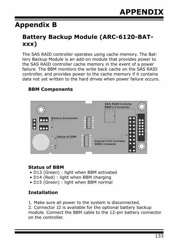
133
APPENDIX
Appendix B
Battery Backup Module (ARC-6120-BAT-xxx)
The SAS RAID controller operates using cache memory. The Bat-tery Backup Module is an add-on module that provides power to the SAS RAID controller cache memory in the event of a power failure. The BBM monitors the write back cache on the SAS RAID controller, and provides power to the cache memory if it contains data not yet written to the hard drives when power failure occurs.
BBM Components
Status of BBM• D13 (Green) : light when BBM activated• D14 (Red) : light when BBM charging• D15 (Green) : light when BBM normal
Installation
1. Make sure all power to the system is disconnected.2. Connector J2 is available for the optional battery backup module. Connect the BBM cable to the 12-pin battery connector on the controller.
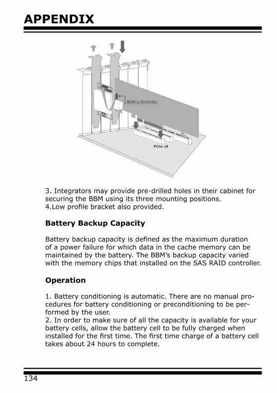
APPENDIX
134
3. Integrators may provide pre-drilled holes in their cabinet for securing the BBM using its three mounting positions. 4.Low profile bracket also provided.
Battery Backup Capacity
Battery backup capacity is defined as the maximum duration of a power failure for which data in the cache memory can be maintained by the battery. The BBM’s backup capacity varied with the memory chips that installed on the SAS RAID controller.
Operation
1. Battery conditioning is automatic. There are no manual pro-cedures for battery conditioning or preconditioning to be per-formed by the user.2. In order to make sure of all the capacity is available for your battery cells, allow the battery cell to be fully charged when installed for the first time. The first time charge of a battery cell takes about 24 hours to complete.
135
APPENDIX
Changing the Battery Backup Module
At some point, the LI-ION battery will no longer accept a charge properly. LI-ION battery life expectancy is anywhere from ap-proximately 1 to 5 years.
1. Shutdown the operating system properly. Make sure that cache memory has been flushed.2. Disconnect the BBM cable from J2 on the SAS RAID controller.3. Disconnect the battery pack cable from JP2 on the BBM.4. Install a new battery pack and connect the new battery pack to JP2.5. Connect the BBBM to J2 on the SAS controller.6. Disable the write-back function from the McBIOS RAID man-ager or McRAID storage manager .
Note:
Do not remove BBM while system is running.
Battery Functionality Test Procedure:1. Writing amount of data into controller volume, about 5GB or bigger.2. Waiting for few seconds, power failed system by remove the power cable3. Check the battery status, make sure the D13 is bright light, and battery beeps every few seconds.4. Power on system, and press Tab/F6 to login controller.5. Check the controller event log, make sure the event shows controller boot up with power recovered.
BBM Specifications
Mechanical• Module Dimension (W x H x D)
37.3 x 13 x 81.6 mm• BBM Connector
2 * 6 box header
Environmental • Operating Temperature
APPENDIX
136
Temperature: -25O C to +75O C• Humidity: 45-85%, non-condensing• Storage Temperature
Temperature: -40O C to 85O C• Humidity: 45-85%, non-condensing
Electrical• Input Voltage
+3.6VDC• On Board Battery Capacity
1100mAH (1*1100mAH)
137
APPENDIX
Appendix C
SNMP Operation & Installation
Overview
The McRAID storage manager includes a firmware-embedded Sim-ple Network Management Protocol (SNMP) agent and SNMP Exten-sion Agent for the SAS RAID controller. An SNMP-based manage-ment application (also known as an SNMP manager) can monitor the disk array. An example of An SNMP management application is Hewlett-Packard’s Open View. The SNMP extension agent can be used to augment the SAS RAID controller if you are already run-ning an SNMP management application at your site.
SNMP Definition
SNMP, an IP-based protocol, has a set of commands for getting the status of target devices. The SNMP management platform is called the SNMP manager, and the managed devices have the SNMP agent loaded. Management data is organized in a hierarchical data structure called the Management Information Base (MIB). These MIBs are defined and sanctioned by various industry associa-tions. The objective is for all vendors to create products in compli-ance with these MIBs so that inter-vendor interoperability can be achieved. If a vendor wishes to include additional device informa-tion that is not specified in a standard MIB, then that is usually done through MIB extensions.
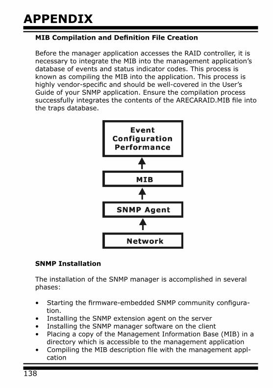
APPENDIX
138
MIB Compilation and Definition File Creation
Before the manager application accesses the RAID controller, it is necessary to integrate the MIB into the management application’s database of events and status indicator codes. This process is known as compiling the MIB into the application. This process is highly vendor-specific and should be well-covered in the User’s Guide of your SNMP application. Ensure the compilation process successfully integrates the contents of the ARECARAID.MIB file into the traps database.
SNMP Installation
The installation of the SNMP manager is accomplished in several phases:
• Starting the firmware-embedded SNMP community configura- tion.• Installing the SNMP extension agent on the server • Installing the SNMP manager software on the client• Placing a copy of the Management Information Base (MIB) in a directory which is accessible to the management application • Compiling the MIB description file with the management appl- cation
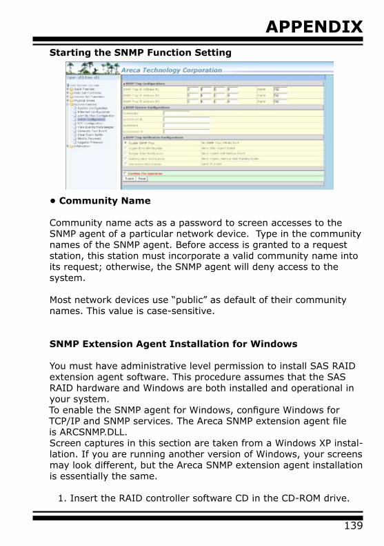
139
APPENDIXStarting the SNMP Function Setting
• Community Name
Community name acts as a password to screen accesses to the SNMP agent of a particular network device. Type in the community names of the SNMP agent. Before access is granted to a request station, this station must incorporate a valid community name into its request; otherwise, the SNMP agent will deny access to the system.
Most network devices use “public” as default of their community names. This value is case-sensitive.
SNMP Extension Agent Installation for Windows
You must have administrative level permission to install SAS RAID extension agent software. This procedure assumes that the SAS RAID hardware and Windows are both installed and operational in your system.
To enable the SNMP agent for Windows, configure Windows for TCP/IP and SNMP services. The Areca SNMP extension agent file is ARCSNMP.DLL.
Screen captures in this section are taken from a Windows XP instal-lation. If you are running another version of Windows, your screens may look different, but the Areca SNMP extension agent installation is essentially the same.
1. Insert the RAID controller software CD in the CD-ROM drive.
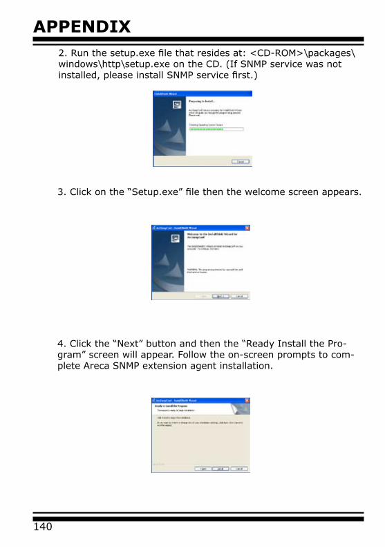
APPENDIX
140
2. Run the setup.exe file that resides at: <CD-ROM>\packages\windows\http\setup.exe on the CD. (If SNMP service was not installed, please install SNMP service first.)
3. Click on the “Setup.exe” file then the welcome screen appears.
4. Click the “Next” button and then the “Ready Install the Pro-gram” screen will appear. Follow the on-screen prompts to com-plete Areca SNMP extension agent installation.

141
APPENDIX5. A Progress bar appears that measures the progress of the Areca SNMP extension agent setup. When this screen completes, you have completed the Areca SNMP extension agent setup.
6. After a successful installation, the “Setup Complete” dialog box of the installation program is displayed. Click the “Finish” button to complete the installation.
Starting SNMP Trap Notification Configurations
To start "SNMP Trap Notification Configruations", There have two methods. First, double-click on the "Areca RAID Controller".
Second, you may also use the "Taskbar Start/programs/Areca Technology Corp/ArcSnmpConf" menus shown below.

APPENDIX
142
SNMP Community ConfigurationsPlease refer to the community name in this appendix.
SNMP Trap Notification ConfigurationsThe "Community Name" should be the same as firmware- embedded SNMP Community. The "SNMP Trap Notification Configurations" include level 1: Serious, level 2: Error, level 3: Warning and level 4: Information. The level 4 covers notification events such as initialization of the controller and initiation of the rebuilding process; Level 3 includes events which require the issuance of warning messages; Level 2 covers notification events which once have happen; Level 1 is the highest level, and covers events the need immediate attention (and action) from the administrator. (Please refer to Appendix E of Email Event Notification Configurations)
SNMP Extension Agent Installation for Linux
You must have administrative level permission to install SAS RAID software. This procedure assumes that the SAS RAID hard-
143
APPENDIX
ware and Linux are installed and operational in your system.
For the SNMP extension agent installation for Linux procedure, please refer to <CD-ROM>\packages\Linux\SNMP\Readme or download from areca.com.tw
SNMP Extension Agent Installation for FreeBSDYou must have administrative level permission to install SAS RAID software. This procedure assumes that the SAS RAID hard-ware and FreeBSD are installed and operational in your system. For the SNMP extension agent installation for FreeBSD procedure please refer to <CD-ROM>\packages\FreeBSD\SNMP\Readme or download from http://www.areca.com.tw
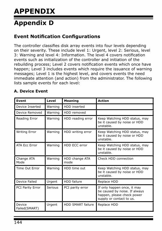
APPENDIX
144
Appendix D
Event Notification Configurations
The controller classifies disk array events into four levels depending on their severity. These include level 1: Urgent, level 2: Serious, level 3: Warning and level 4: Information. The level 4 covers notification events such as initialization of the controller and initiation of the rebuilding process; Level 2 covers notification events which once have happen; Level 3 includes events which require the issuance of warning messages; Level 1 is the highest level, and covers events the need immediate attention (and action) from the administrator. The following lists sample events for each level:
Event Level Meaning Action
Device Inserted Warning HDD inserted
Device Removed Warning HDD removed
Reading Error Warning HDD reading error Keep Watching HDD status, may be it caused by noise or HDD unstable.
Writing Error Warning HDD writing error Keep Watching HDD status, may be it caused by noise or HDD unstable.
ATA Ecc Error Warning HDD ECC error Keep Watching HDD status, may be it caused by noise or HDD unstable.
Change ATA Mode
Warning HDD change ATA mode
Check HDD connection
Time Out Error Warning HDD time out Keep Watching HDD status, may be it caused by noise or HDD unstable.
Device Failed Urgent HDD failure Replace HDD
PCI Parity Error Serious PCI parity error If only happen once, it may be caused by noise. If always happen, please check power supply or contact to us.
Device Failed(SMART)
Urgent HDD SMART failure Replace HDD
A. Device Event
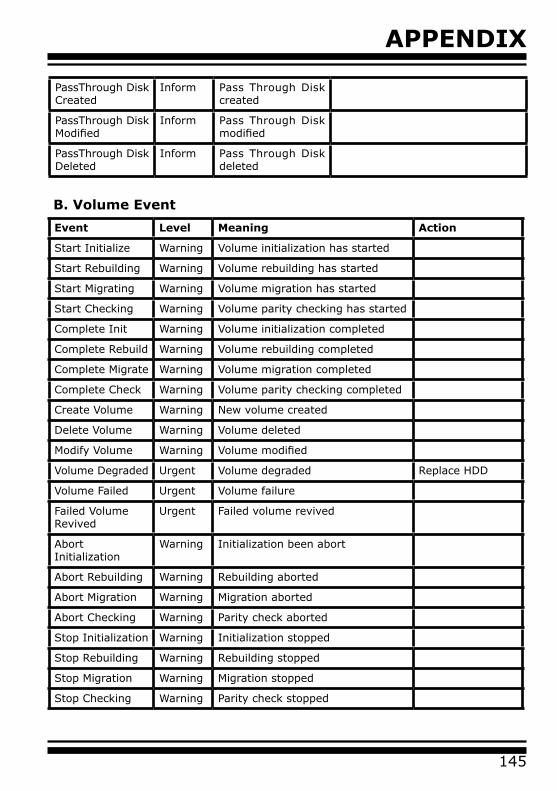
145
APPENDIX
Event Level Meaning Action
Start Initialize Warning Volume initialization has started
Start Rebuilding Warning Volume rebuilding has started
Start Migrating Warning Volume migration has started
Start Checking Warning Volume parity checking has started
Complete Init Warning Volume initialization completed
Complete Rebuild Warning Volume rebuilding completed
Complete Migrate Warning Volume migration completed
Complete Check Warning Volume parity checking completed
Create Volume Warning New volume created
Delete Volume Warning Volume deleted
Modify Volume Warning Volume modified
Volume Degraded Urgent Volume degraded Replace HDD
Volume Failed Urgent Volume failure
Failed Volume Revived
Urgent Failed volume revived
Abort Initialization
Warning Initialization been abort
Abort Rebuilding Warning Rebuilding aborted
Abort Migration Warning Migration aborted
Abort Checking Warning Parity check aborted
Stop Initialization Warning Initialization stopped
Stop Rebuilding Warning Rebuilding stopped
Stop Migration Warning Migration stopped
Stop Checking Warning Parity check stopped
B. Volume Event
PassThrough Disk Created
Inform Pass Through Disk created
PassThrough Disk Modified
Inform Pass Through Disk modified
PassThrough Disk Deleted
Inform Pass Through Disk deleted
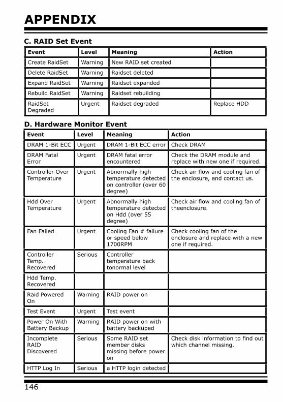
APPENDIX
146
C. RAID Set Event
Event Level Meaning Action
Create RaidSet Warning New RAID set created
Delete RaidSet Warning Raidset deleted
Expand RaidSet Warning Raidset expanded
Rebuild RaidSet Warning Raidset rebuilding
RaidSet Degraded
Urgent Raidset degraded Replace HDD
D. Hardware Monitor EventEvent Level Meaning Action
DRAM 1-Bit ECC Urgent DRAM 1-Bit ECC error Check DRAM
DRAM Fatal Error
Urgent DRAM fatal error encountered
Check the DRAM module and replace with new one if required.
Controller Over Temperature
Urgent Abnormally high temperature detected on controller (over 60 degree)
Check air flow and cooling fan of the enclosure, and contact us.
Hdd Over Temperature
Urgent Abnormally high temperature detected on Hdd (over 55 degree)
Check air flow and cooling fan of theenclosure.
Fan Failed Urgent Cooling Fan # failure or speed below 1700RPM
Check cooling fan of the enclosure and replace with a new one if required.
Controller Temp.Recovered
Serious Controller temperature back tonormal level
Hdd Temp. Recovered
Raid Powered On
Warning RAID power on
Test Event Urgent Test event
Power On With Battery Backup
Warning RAID power on with battery backuped
Incomplete RAID Discovered
Serious Some RAID set member disks missing before power on
Check disk information to find out which channel missing.
HTTP Log In Serious a HTTP login detected

147
APPENDIX
Telnet Log Serious a Telnet login detected
InVT100 Log In Serious a VT100 login detected
API Log In Serious a API login detected
Lost Rebuilding/MigrationLBA
Urgent Some rebuilding/migration raidset member disks missing before power on.
Reinserted the missing member disk back, controller will continued the incompleted rebuilding/migration.
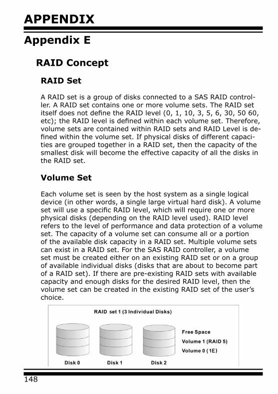
APPENDIX
148
Appendix E
RAID Concept
RAID Set
A RAID set is a group of disks connected to a SAS RAID control-ler. A RAID set contains one or more volume sets. The RAID set itself does not define the RAID level (0, 1, 10, 3, 5, 6, 30, 50 60, etc); the RAID level is defined within each volume set. Therefore, volume sets are contained within RAID sets and RAID Level is de-fined within the volume set. If physical disks of different capaci-ties are grouped together in a RAID set, then the capacity of the smallest disk will become the effective capacity of all the disks in the RAID set.
Volume Set
Each volume set is seen by the host system as a single logical device (in other words, a single large virtual hard disk). A volume set will use a specific RAID level, which will require one or more physical disks (depending on the RAID level used). RAID level refers to the level of performance and data protection of a volume set. The capacity of a volume set can consume all or a portion of the available disk capacity in a RAID set. Multiple volume sets can exist in a RAID set. For the SAS RAID controller, a volume set must be created either on an existing RAID set or on a group of available individual disks (disks that are about to become part of a RAID set). If there are pre-existing RAID sets with available capacity and enough disks for the desired RAID level, then the volume set can be created in the existing RAID set of the user’s choice.
149
APPENDIXIn the illustration, volume 1 can be assigned a RAID level 5 of operation while volume 0 might be assigned a RAID level 10 of operation. Alternatively, the free space can be used to create vol-ume 2, which could then be set to use RAID level 5.
Ease of Use Features
• Foreground Availability/Background Initialization
RAID 0 and RAID 1 volume sets can be used immediately after creation because they do not create parity data. However, RAID 3, 5, 6, 30, 50 or 60 volume sets must be initialized to generate parity information. In Background Initialization, the initializa-tion proceeds as a background task, and the volume set is fully accessible for system reads and writes. The operating system can instantly access the newly created arrays without requir-ing a reboot and without waiting for initialization to complete. Furthermore, the volume set is protected against disk failures while initialing. If using Foreground Initialization, the initializa-tion process must be completed before the volume set is ready for system accesses.
• Online Array Roaming
The SAS RAID controllers store RAID configuration information on the disk drives. The controller therefore protects the con-figuration settings in the event of controller failure. Online array roaming allows the administrators the ability to move a com-plete RAID set to another system without losing RAID configura-tion information or data on that RAID set. Therefore, if a server fails, the RAID set disk drives can be moved to another server with an Areca SAS/SATA RAID controllers and the disks can be inserted in any order.
• Online Capacity Expansion
Online Capacity Expansion makes it possible to add one or more physical drives to a volume set without interrupting server op-eration, eliminating the need to backup and restore after recon-figuration of the RAID set. When disks are added to a RAID set, unused capacity is added to the end of the RAID set. Then, data
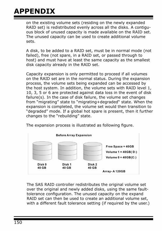
APPENDIX
150
on the existing volume sets (residing on the newly expanded RAID set) is redistributed evenly across all the disks. A contigu-ous block of unused capacity is made available on the RAID set. The unused capacity can be used to create additional volume sets.
A disk, to be added to a RAID set, must be in normal mode (not failed), free (not spare, in a RAID set, or passed through to host) and must have at least the same capacity as the smallest disk capacity already in the RAID set.
Capacity expansion is only permitted to proceed if all volumes on the RAID set are in the normal status. During the expansion process, the volume sets being expanded can be accessed by the host system. In addition, the volume sets with RAID level 1, 10, 3, 5 or 6 are protected against data loss in the event of disk failure(s). In the case of disk failure, the volume set changes from “migrating” state to “migrating+degraded“ state. When the expansion is completed, the volume set would then transition to “degraded” mode. If a global hot spare is present, then it further changes to the “rebuilding” state. The expansion process is illustrated as following figure.
The SAS RAID controller redistributes the original volume set over the original and newly added disks, using the same fault-tolerance configuration. The unused capacity on the expand RAID set can then be used to create an additional volume set, with a different fault tolerance setting (if required by the user.)
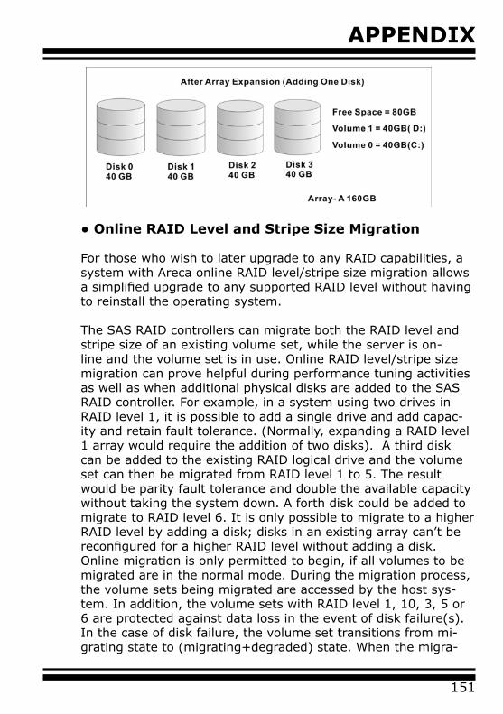
151
APPENDIX
• Online RAID Level and Stripe Size Migration
For those who wish to later upgrade to any RAID capabilities, a system with Areca online RAID level/stripe size migration allows a simplified upgrade to any supported RAID level without having to reinstall the operating system. The SAS RAID controllers can migrate both the RAID level and stripe size of an existing volume set, while the server is on-line and the volume set is in use. Online RAID level/stripe size migration can prove helpful during performance tuning activities as well as when additional physical disks are added to the SAS RAID controller. For example, in a system using two drives in RAID level 1, it is possible to add a single drive and add capac-ity and retain fault tolerance. (Normally, expanding a RAID level 1 array would require the addition of two disks). A third disk can be added to the existing RAID logical drive and the volume set can then be migrated from RAID level 1 to 5. The result would be parity fault tolerance and double the available capacity without taking the system down. A forth disk could be added to migrate to RAID level 6. It is only possible to migrate to a higher RAID level by adding a disk; disks in an existing array can’t be reconfigured for a higher RAID level without adding a disk.Online migration is only permitted to begin, if all volumes to be migrated are in the normal mode. During the migration process, the volume sets being migrated are accessed by the host sys-tem. In addition, the volume sets with RAID level 1, 10, 3, 5 or 6 are protected against data loss in the event of disk failure(s). In the case of disk failure, the volume set transitions from mi-grating state to (migrating+degraded) state. When the migra-
APPENDIX
152
tion is completed, the volume set transitions to degraded mode. If a global hot spare is present, then it further transitions to rebuilding state.
• Online Volume Expansion
Performing a volume expansion on the controller is the process of growing only the size of the latest volume. A more flexible op-tion is for the array to concatenate an additional drive into the RAID set and then expand the volumes on the fly. This happens transparently while the volumes are online, but, at the end of the process, the operating system will detect free space at after the existing volume.
Windows, NetWare and other advanced operating systems sup-port volume expansion, which enables you to incorporate the additional free space within the volume into the operating sys-tem partition. The operating system partition is extended to incorporate the free space so it can be used by the operating system without creating a new operating system partition.
You can use the Diskpart.exe command line utility, included with Windows Server 2003 or the Windows 2000 Resource Kit, to ex-tend an existing partition into free space in the dynamic disk.
Third-party software vendors have created utilities that can be used to repartition disks without data loss. Most of these utilities work offline. Partition Magic is one such utility.
High availability
• Global Hot Spares
A Global Hot Spare is an unused online available drive, which is ready for replacing the failure disk. The Global Hot Spare is one of the most important features that SAS RAID controllers provide to deliver a high degree of fault-tolerance. A Global Hot Spare is a spare physical drive that has been marked as a global hot spare and therefore is not a member of any RAID set. If a disk drive used in a volume set fails, then the Global Hot Spare will
153
APPENDIX
automatically take its place and he data previously located on the failed drive is reconstructed on the Global Hot Spare.
For this feature to work properly, the global hot spare must have at least the same capacity as the drive it replaces. Global Hot Spares only work with RAID level 1, 10, 3, 5, 6, 30, 50, or 60 volume set. You can configure up to three global hot spares with SAS RAID controller.
The “Create Hot Spare” option gives you the ability to define a global hot spare disk drive. To effectively use the global hot spare feature, you must always maintain at least one drive that is marked as a global spare.
• Hot-Swap Disk Drive Support
The SAS RAID controller chip includes a protection circuit that supports the replacement of SAS/SATA hard disk drives without having to shut down or reboot the system. A removable hard drive tray can deliver “hot swappable” fault-tolerant RAID solu-tions. This feature provides advanced fault tolerant RAID protec-tion and “online” drive replacement.
• Auto Declare Hot-Spare
If a disk drive is brought online into a system operating in de-graded mode, the SAS RAID controllers will automatically de-clare the new disk as a spare and begin rebuilding the degraded volume. The Auto Declare Hot-Spare function requires that the smallest drive contained within the volume set in which the failure occurred.
In the normal status, the newly installed drive will be reconfig-ured an online free disk. But, the newly-installed drive is auto-matically assigned as a hot spare if any hot spare disk was used to rebuild and without new installed drive replaced it. In this condition, the Auto Declare Hot-Spare status will be disappeared if the RAID subsystem has since powered off/on.
Important:
The hot spare must have at least the same capacity as the drive it replaces.
APPENDIX
154
The Hot-Swap function can be used to rebuild disk drives in ar-rays with data redundancy such as RAID level 1, 10, 3, 5, 6, 30, 50 and 60. • Auto Rebuilding
If a hot spare is available, the rebuild starts automatically when a drive fails. The SAS RAID controllers automatically and trans-parently rebuild failed drives in the background at user-definable rebuild rates. If a hot spare is not available, the failed disk drive must be re-placed with a new disk drive so that the data on the failed drive can be automatically rebuilt and so that fault tolerance can be maintained.
The SAS RAID controllers will automatically restart the system and rebuilding process if the system is shut down or powered off abnormally during a reconstruction procedure condition. When a disk is hot swapped, although the system is functionally operational, the system may no longer be fault tolerant. Fault tolerance will be lost until the removed drive is replaced and the rebuild operation is completed.
During the automatic rebuild process, system activity will contin-ue as normal, however, the system performance and fault toler-ance will be affected.
• Adjustable Rebuild Priority Rebuilding a degraded volume incurs a load on the RAID subsys-tem. The SAS RAID controllers allow the user to select the rebuild priority to balance volume access and rebuild tasks appropriately. The Background Task Priority is a relative indication of how much time the controller devotes to a background operation, such as rebuilding or migrating. The SAS RAID controller allows user to choose the task priority (Ultra Low (5%), Low (20%), Medium (50%), High (80%)) to bal-ance volume set access and background tasks appropriately. For
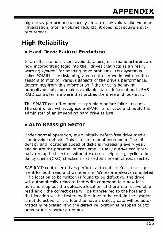
155
APPENDIXhigh array performance, specify an Ultra Low value. Like volume initialization, after a volume rebuilds, it does not require a sys-tem reboot.
High Reliability
• Hard Drive Failure Prediction
In an effort to help users avoid data loss, disk manufacturers are now incorporating logic into their drives that acts as an "early warning system" for pending drive problems. This system is called SMART. The disk integrated controller works with multiple sensors to monitor various aspects of the drive's performance, determines from this information if the drive is behaving normally or not, and makes available status information to SAS RAID controller firmware that probes the drive and look at it.
The SMART can often predict a problem before failure occurs. The controllers will recognize a SMART error code and notify the administer of an impending hard drive failure.
• Auto Reassign Sector
Under normal operation, even initially defect-free drive media can develop defects. This is a common phenomenon. The bit density and rotational speed of disks is increasing every year, and so are the potential of problems. Usually a drive can inter-nally remap bad sectors without external help using cyclic redun-dancy check (CRC) checksums stored at the end of each sector.
SAS RAID controller drives perform automatic defect re-assign-ment for both read and write errors. Writes are always completed - if a location to be written is found to be defective, the drive will automatically relocate that write command to a new loca-tion and map out the defective location. If there is a recoverable read error, the correct data will be transferred to the host and that location will be tested by the drive to be certain the location is not defective. If it is found to have a defect, data will be auto-matically relocated, and the defective location is mapped out to prevent future write attempts.

APPENDIX
156
In the event of an unrecoverable read error, the error will be re-ported to the host and the location will be flagged as being po-tentially defective. A subsequent write to that location will initiate a sector test and relocation should that location prove to have a defect. Auto Reassign Sector does not affect disk subsystem performance because it runs as a background task. Auto Reassign Sector discontinues when the operating system makes a request.
• Consistency Check A consistency check is a process that verifies the integrity of re-dundant data. To verify RAID 3, 5, 6, 30, 50 or 60 redundancy, a consistency check reads all associated data blocks, computes par-ity, reads parity, and verifies that the computed parity matches the read parity. Consistency checks are very important because they detect and correct parity errors or bad disk blocks in the drive. A consistency check forces every block on a volume to be read, and any bad blocks are marked; those blocks are not used again. This is criti-cal and important because a bad disk block can prevent a disk rebuild from completing. We strongly recommend that you run consistency checks on a regular basis—at least once per week. Note that consistency checks degrade performance, so you should run them when the system load can tolerate it.
Data Protection • Battery Backup
The SAS RAID controllers are armed with a Battery Backup Mod-ule (BBM). While a Uninterruptible Power Supply (UPS) protects most servers from power fluctuations or failures, a BBM provides an additional level of protection. In the event of a power failure, a BBM supplies power to retain data in the SAS RAID controller’s cache, thereby permitting any potentially dirty data in the cache to be flushed out to secondary storage when power is restored.
The batteries in the BBM are recharged continuously through a trickle-charging process whenever the system power is on. The
157
APPENDIXbatteries protect data in a failed server for up to three or four days, depending on the size of the memory module. Under nor-mal operating conditions, the batteries last for three years before replacement is necessary.
• Recovery ROM
The SAS RAID controller firmware is stored on the flash ROM and is executed by the I/O processor. The firmware can also be up-dated through the SAS RAID controllers PCIe bus port or Ether-net port without the need to replace any hardware chips. During the controller firmware upgrade flash process, it is possible for a problem to occur resulting in corruption of the controller firm-ware. With our Redundant Flash Image feature, the controller will revert back to the last known version of firmware and continue operating. This reduces the risk of system failure due to firmware crash.

APPENDIX
158
Appendix F
Understanding RAID RAID is an acronym for Redundant Array of Independent Disks. It is an array of multiple independent hard disk drives that provides high performance and fault tolerance. The SAS RAID control-ler implements several levels of the Berkeley RAID technology. An appropriate RAID level is selected when the volume sets are defined or created. This decision should be based on the desired disk capacity, data availability (fault tolerance or redundancy), and disk performance. The following section discusses the RAID levels supported by the SAS RAID controllers.
The SAS RAID controllers makes the RAID implementation and the disks’ physical configuration transparent to the host operating system. This means that the host operating system drivers and software utilities are not affected, regardless of the RAID level selected. Correct installation of the disk array and the control-ler requires a proper understanding of RAID technology and the concepts.
RAID 0
RAID 0, also referred to as striping, writes stripes of data across multiple disk drives instead of just one disk drive. RAID 0 does not provide any data redundancy, but does offer the best High-speed data throughput. RAID 0 breaks up data into smaller blocks and then writes a block to each drive in the array. Disk strip-ing enhances performance because multiple drives are accessed simultaneously; the reliability of RAID level 0 is less because the entire array will fail if any one disk drive fails.
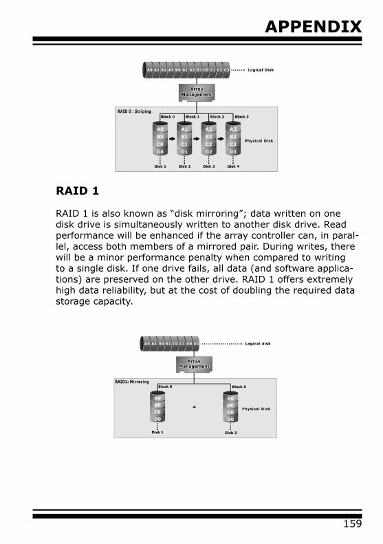
159
APPENDIX
RAID 1
RAID 1 is also known as “disk mirroring”; data written on one disk drive is simultaneously written to another disk drive. Read performance will be enhanced if the array controller can, in paral-lel, access both members of a mirrored pair. During writes, there will be a minor performance penalty when compared to writing to a single disk. If one drive fails, all data (and software applica-tions) are preserved on the other drive. RAID 1 offers extremely high data reliability, but at the cost of doubling the required data storage capacity.
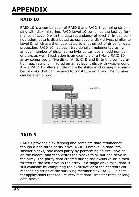
APPENDIX
160
RAID 10
RAID 10 is a combination of RAID 0 and RAID 1, combing strip-ping with disk mirroring. RAID Level 10 combines the fast perfor-mance of Level 0 with the data redundancy of level 1. In this con-figuration, data is distributed across several disk drives, similar to Level 0, which are then duplicated to another set of drive for data protection. RAID 10 has been traditionally implemented using an even number of disks, some hybrids can use an odd number of disks as well. Illustration is an example of a hybrid RAID 10 array comprised of five disks; A, B, C, D and E. In this configura-tion, each strip is mirrored on an adjacent disk with wrap-around. Areca RAID 10 offers a little more flexibility in choosing the num-ber of disks that can be used to constitute an array. The number can be even or odd.
RAID 3
RAID 3 provides disk striping and complete data redundancy though a dedicated parity drive. RAID 3 breaks up data into smaller blocks, calculates parity by performing an exclusive-or on the blocks, and then writes the blocks to all but one drive in the array. The parity data created during the exclusive-or is then written to the last drive in the array. If a single drive fails, data is still available by computing the exclusive-or of the contents cor-responding strips of the surviving member disk. RAID 3 is best for applications that require very fast data- transfer rates or long data blocks.
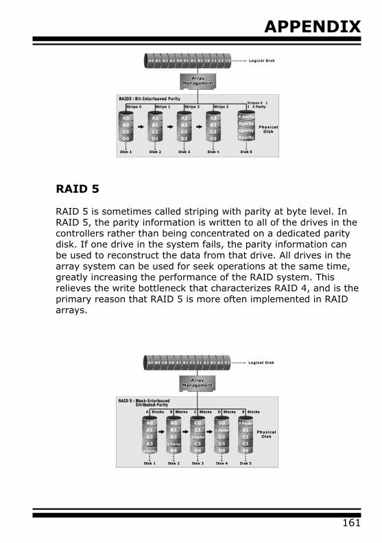
161
APPENDIX
RAID 5
RAID 5 is sometimes called striping with parity at byte level. In RAID 5, the parity information is written to all of the drives in the controllers rather than being concentrated on a dedicated parity disk. If one drive in the system fails, the parity information can be used to reconstruct the data from that drive. All drives in the array system can be used for seek operations at the same time, greatly increasing the performance of the RAID system. This relieves the write bottleneck that characterizes RAID 4, and is the primary reason that RAID 5 is more often implemented in RAID arrays.

APPENDIX
162
RAID 6
RAID 6 provides the highest reliability. It is similar to RAID 5, but it performs two different parity computations or the same compu-tation on overlapping subsets of the data. RAID 6 can offer fault tolerance greater than RAID 1 or RAID 5 but only consumes the capacity of 2 disk drives for distributed parity data. RAID 6 is an extension of RAID 5 but uses a second, independent distributed parity scheme. Data is striped on a block level across a set of drives, and then a second set of parity is calculated and written across all of the drives.
RAID x0
RAID level-x0 refers to RAID level 30, 50 and 60. RAID x0 is a combination multiple RAID x volume sets with RAID 0 (striping). Striping helps to increase capacity and performance without add-ing disks to each RAID x array. The operating system uses the spanned volume in the same way as a regular volume. Up to one drive in each sub-volume (RAID 3 or 5) may fail without loss of data. Up to two drives in each sub-volume (RAID 6) may fail with-out loss of data.
RAID level x0 allows more physical drives in an array. The ben-efits of doing so are larger volume sets, increased performance, and increased reliability.The following illustration is an example of a RAID level x0 logical drive.
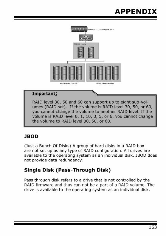
163
APPENDIX
Important:
RAID level 30, 50 and 60 can support up to eight sub-Vol-umes (RAID set). If the volume is RAID level 30, 50, or 60, you cannot change the volume to another RAID level. If the volume is RAID level 0, 1, 10, 3, 5, or 6, you cannot change the volume to RAID level 30, 50, or 60.
JBOD
(Just a Bunch Of Disks) A group of hard disks in a RAID box are not set up as any type of RAID configuration. All drives are available to the operating system as an individual disk. JBOD does not provide data redundancy.
Single Disk (Pass-Through Disk)
Pass through disk refers to a drive that is not controlled by the RAID firmware and thus can not be a part of a RAID volume. The drive is available to the operating system as an individual disk.
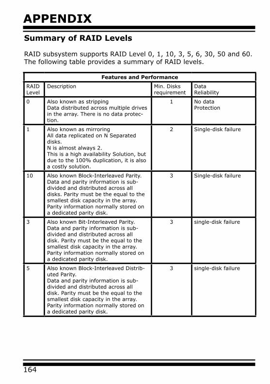
APPENDIX
164
Summary of RAID Levels
RAID subsystem supports RAID Level 0, 1, 10, 3, 5, 6, 30, 50 and 60. The following table provides a summary of RAID levels.
Features and Performance
RAIDLevel
Description Min. Disks requirement
Data Reliability
0 Also known as strippingData distributed across multiple drives in the array. There is no data protec-tion.
1 No dataProtection
1 Also known as mirroringAll data replicated on N Separated disks. N is almost always 2.This is a high availability Solution, but due to the 100% duplication, it is also a costly solution.
2 Single-disk failure
10 Also known Block-Interleaved Parity.Data and parity information is sub-divided and distributed across all disks. Parity must be the equal to the smallest disk capacity in the array. Parity information normally stored on a dedicated parity disk.
3 Single-disk failure
3 Also known Bit-Interleaved Parity.Data and parity information is sub-divided and distributed across all disk. Parity must be the equal to the smallest disk capacity in the array. Parity information normally stored on a dedicated parity disk.
3 single-disk failure
5 Also known Block-Interleaved Distrib-uted Parity.Data and parity information is sub-divided and distributed across all disk. Parity must be the equal to the smallest disk capacity in the array. Parity information normally stored on a dedicated parity disk.
3 single-disk failure
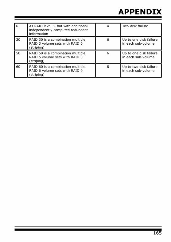
165
APPENDIX
6 As RAID level 5, but with additional independently computed redundant information
4 Two-disk failure
30 RAID 30 is a combination multiple RAID 3 volume sets with RAID 0 (striping)
6 Up to one disk failure in each sub-volume
50 RAID 50 is a combination multiple RAID 5 volume sets with RAID 0 (striping)
6 Up to one disk failure in each sub-volume
60 RAID 60 is a combination multiple RAID 6 volume sets with RAID 0 (striping)
8 Up to two disk failure in each sub-volume

HISTORY
166
Revision Page Description
1.0 p.133 Deleted note description
Version History