AquiStar CT2X - Geotech · PDF fileStrapping the sensor body with tie wraps or tape will ......
38
AquiStar ® CT2X Conductivity Smart Sensor (With Pressure Option) INSTRUCTION MANUAL For PSIG sensors, refer to page 11 regarding desiccant use!
-
Upload
truongtruc -
Category
Documents
-
view
217 -
download
3
Transcript of AquiStar CT2X - Geotech · PDF fileStrapping the sensor body with tie wraps or tape will ......

AquiStar® CT2XConductivity Smart Sensor
(With Pressure Option)
INSTRUCTION MANUAL
For PSIG
sensors, refer
to page 11
regarding
desiccant
use!

1
Table of ContentsIntroduction ......................................................................................................................3
What is the CT2X with Pressure Option? ..................................................................3Initial Inspection and Handling .................................................................................3Do’s and Don’ts .........................................................................................................3
Installation and Operation .................................................................................................4Connecting to External Power ...................................................................................4Connecting the CT2X to a Computer ........................................................................4Installing the Aqua4Plus Software .............................................................................4Selecting Linear or Non-Linear Mode .......................................................................5Installing the Sensor ..................................................................................................6Collecting Data ..........................................................................................................7
Maintenance ....................................................................................................................10Changing Batteries ...................................................................................................10Removing Debris from End Cone on Pressure Units ..............................................10Desiccant Tubes on Vented Pressure Units ..............................................................11Miscellaneous ..........................................................................................................11
Trouble Shooting .............................................................................................................12Erratic Readings .......................................................................................................12Oscillating Readings Over Time ..............................................................................12Zero Readings When Pressurized ............................................................................12Grounding Issues .....................................................................................................12
Appendix A: Technical Specifi cations ............................................................................14Wiring Information ..................................................................................................14Dimensions and Specifi cations ................................................................................15
Appendix B: Field Calibration ........................................................................................17Preparing for Calibration .........................................................................................17Field Calibration — Conductivity ...........................................................................17Field Calibration — Pressure ...................................................................................19
Appendix C: Measuring Elevation or Depth-to-Water ...................................................20Groundwater Elevation Calibration .........................................................................21
Appendix D: Alternate Connection Options ...................................................................22Connecting via RS232 Serial Port ...........................................................................22Connecting with a USB/Serial Adapter ...................................................................22
Appendix E: Reading the CT2X via Direct Read ..........................................................24Setting Units for Direct Read ..................................................................................24Reading Via Modbus® RTU .....................................................................................25Reading Via SDI-12 .................................................................................................27
Appendix F: Reading Salinity .........................................................................................30Appendix G: Battery Changing Details ..........................................................................31Reordering Information ..................................................................................................35Limited Warranty/Disclaimer - AquiStar® CT2X SENSORS ........................................36

2
Information in this document is subject to change without notice and does not represent a commitment on the part of the manufacturer. No part of this manual may be reproduced or transmitted in any form or by any means, electronic or mechanical, including photocopying and recording, for any purpose without the express written permission of the manufacturer.
©1997 - 2013 Instrumentation Northwest, Inc.Registered trademarks and trademarks belong to their respective owners.

3Introduction
What is the CT2X with Pressure Option?
The AquiStar® CT2X is a submersible conductivity/temperature sensor with built-in datalogging. This device stores thousands of records of conductivity, temperature, and time data. The CT2X is also available with a pressure option based on INW’s popular CT2X Smart Sensor, giving added functionality in the same sensor housing. The conductivity channel can also be used to measure salinity. See Appendix F for details.
The CT2X incorporates 4-pole electrode cell measurement technology. This technol-ogy reduces fringe fi eld interference errors, lessens inaccuracy caused by polarization effects, and lowers contact resistance problems. Four-pole electrode technology also allows users to work with one electrode over a wide range of conductivity.
The conductivity probe is constructed of epoxy/graphite, making it extremely durable for use in rugged fi eld conditions. To clean, simply scrub with a small brush.
The CT2X is powered internally with 2 AA batteries or with an external auxiliary power supply for data intensive applications.
Most users will use the CT2X with INW’s Aqua4Plus software. However, the CT2X is quite versatile, communicating via either Modbus® or SDI-12 interfaces, allowing you to do the following:
• Read a CT2X via the Modbus® protocol using your own software.• Read a CT2X via SDI-12 protocol.• Display readings from a CT2X on a panel meter.
If you want to use one of these methods, please see Appendix E.
Initial Inspection and Handling
Upon receipt of your smart sensor, inspect the shipping package for damage. If any damage is apparent, note the signs of damage on the appropriate shipping form. After opening the carton, look for concealed damage, such as a cut cable. If concealed damage is found, immediately fi le a claim with the carrier.
Do’s and Don’tsDo handle the device with care.Do store the device in a dry, inside area
when not in use.Do install a desiccant tube (pressure version
only) if you are doing long-term outdoor monitoring with a gauge unit.
Do install the device so that the connector end is kept dry.
Don’t support the device with the connector. Use a strain relief device to take the tension off the connectors.
Don’t allow the device to free-fall down a well as impact damage can occur.
Don’t bang or drop the device on hard objects.

4Installation and Operation
Connecting to External Power
The CT2X comes with two AA internal batteries. This provides enough power for at least one year of operation at the rate of four measurements per hour. (See Battery Life Calculation section in Appendix A for further details.)
If auxiliary power is desired, you can use a 6 - 13 VDC supply that can provide 15 mA. Connect to Vaux++ (pin 1 - white) and Ground (pin 5 - blue) or contact INW for auxiliary power supplies.
Connecting the CT2X to a Computer
Connect the CT2X to your computer’s USB port, as shown below. Drivers and installation instructions come with the adapter. (For alternate connection options, see Appendix D.)
Connect the CT2X to your PC using a USB to RS485 adapter. (See Appendix D for alternate connection options.)
Installing the Aqua4Plus Software
The CT2X comes with the Aqua4Plus host software that is installed on your PC or laptop. Use this software to program the datalogger, to retrieve data from the logger, to view collected data, and to export data to external fi les for use with spreadsheets or databases.
Refer to the Aqua4Plus software manual for details on installing and using Aqua4Plus.
PC or LaptopComputer
USB Port
USB to RS485Adapter
CT2X
CT2XCable

5Using the CT2X Without Aqua4Plus
Most users will use the CT2X with INW’s Aqua4Plus software. However, the CT2X is quite versatile, communicating via either Modbus® or SDI-12 interfaces, allowing you to do the following:
• Read a CT2X via the Modbus® protocol using your own software.• Read a CT2X via SDI-12 protocol.• Display readings from a CT2X on a panel meter.
If you want to use one of these methods, see Appendix E.
Selecting Linear or Non-Linear Mode
All conductivity measurements are sensitive to temperature change. The CT2X has built-in temperature compensation to correct for changes in temperature. As a user, you can select either a linear temperature compensation method or a non-linear (nLFn) compensation method.
In the linear mode, a constant temperature coeffi cient is applied to the readings. This defaults to 2.1% per degree C, which works well for a wide range of applications. If you want to use the linear method with a different coeffi cient, then enter that coeffi cient in the Temp Coef box on the Field Calibration window. Natural waters, such as ground water, streams, and rivers, often have a very low conductivity and do not respond to temperature in a linear fashion. For this situation, the CT2X provides a non-linear mode, which uses a complex formula to calculate and apply temperature compensation to the readings. This method meets the DIN EN 27888 standards. If you want to use the non-linear method, checkmark the Non-Linear box on the Field Calibration window. The temperature coeffi cient box will disappear.
Enter a temperature coeffi cient for linear mode, if not using default.

6
Installing the Sensor
Lower the sensor to the desired depth. Fasten the cable to the well head using tie wraps or a weather proof strain-relief system. When securing a vented cable, make sure not to pinch the cable too tightly or the vent tube inside the cable jacket may be sealed off. Take a measurement to insure the sensor is not installed below its maximum range.
Be sure the supplied cap is securely placed on the weather-resistant connector at the top of the cable. Do not install such that the connector might become submerged with changing weather conditions. The connector can withstand incidental splashing but is not designed to be submerged.
For vented sensors, if at all possible, install the sensor so that the desiccant tube will not fl ood or lie in water. (Note: Though the hydrophobic fi lter will prevent water intrusion via the desiccant tube at one to two feet of submergence, care must still be taken to keep the cable connector from being submerged.)
The sensor can be installed in any position; however, when it leaves the factory it is tested in the vertical position. Strapping the sensor body with tie wraps or tape will not hurt it. INW can provide an optional 1/4” NPT input adapter which is interchange-able with the standard end cone for those applications where it is necessary to directly attach the sensor to a pipe, tank or other pipe port. If the sensor is being installed in a fl uid environment other than water, be sure to check the compatibility of the fl uid with the wetted parts of the sensor. INW can provide a variety of seal materials if you are planning to install the sensor in an environment other than water.
To use Non-Linear temperature compensation, checkmark this box.

7Collecting Data
Following is a brief overview on using Aqua4Plus to collect data. Please refer to the Aqua4Plus Instruction Manual for further details on confi guring and using Aqua4Plus.
Real Time Monitor
Click Single to get a single reading.
Click Start to get a reading once a second.
Click Stop to stop the reading.
Note: These are snapshot readings and are not recorded on the sensor. On sensors with fi rmware versions lower than 2.0, the pressure is displayed in the fi rst column and temperature in the second. On sensors with fi rmware versions 2.0 and higher, the temperature is displayed in the fi rst column and pressure in the second.
The Real Time Monitor gives a snapshot of the current readings on the sensor.

8Setting up a Data Recording Session
Click the tool button. A Session Profi le Window will open. Refer to the Aqua4Plus Instruction Manual for details in describing your session profi le. Click the Start button to save the session to the sensor and begin recording.
Retrieving Data from the Sensor/Datalogger
• Click on the session you want to upload.• Click the tool button.• Select a fi le location.• Click Save.• Click Start.
Select the data session you are ready to upload.
Using the Session Profi le Window, describe the test steps for your particular test.

9Viewing Data
• Click the tool button to view data as a table.• Click the tool button to view data as a graph.• Navigate to the desired fi le, then click the Open button. (If the File Open box does
not appear, click the File Menu, then select Open.)
The File Display Window displays your data in a tabular format.
The Graph Window displays your data on an X Y coordinate graph.

10Exporting Data to .csv or .xls Files
• Using the File Display window, open the fi le you want to export.• Click on the tool button.• Select a fi le location and enter a name for the fi le.• Select a fi le type. • Click Save.
A Word About Units
Readings from the CT2X Smart Sensor can be displayed in various units, such as PSI, Ft. H2O, or mm H2O for pressure, or degrees Celsius or degrees Fahrenheit for temperature. Select the units you want from the Options | Units menu.
Maintenance
Changing Batteries
Battery Type: Two standard AA Alkaline batteries.
Because changing the batteries involves opening the water-tight seal, this must be done in a clean, dry environment to avoid contamination or moisture damage to the circuitry.
Refer to Appendix G for details on opening the housing and replacing the batteries.
Removing Debris from End Cone on Pressure Units
At times mud, silt, or other debris may foul the water inlets to the pressure element. The end cone can be removed to clean out the debris.
1. Gently twist off end cone portion only - do not twist off pressure element!2. Remove debris. Take care not to poke anything into the sensor. This can
damage the sensor element and void the warranty.3. Replace and retighten the end cone.
Gently twist off the end cone, and then carefully remove debris.
Pressure element
Water inlet
End cone

11Desiccant Tubes on Vented Pressure Units
On vented pressure sensors, inspect the desiccant tube at least once every two months. The desiccant tube prevents moisture in the air from being sucked into the vent tube, which can cause erratic readings and sensor damage.
The desiccant tube is fi lled with blue silica gel beads. A locking barb and a hydrophobic water fi lter are attached to the end of the desiccant tube. This fi lter prolongs the life of the desiccant as much as three times over a desiccant tube without the fi lter.
Install the sensor so that the desiccant tube will not fl ood or lie in water.
The desiccant is a bright blue color when active and dry. As moisture is absorbed the color will begin to fade, becoming a light pink, which indicates full saturation and time to replace. Replacement desiccant and hydrophobic fi lters can be purchased from INW; please contact an INW sales engineer at 1-800-776-9355 for more information.
The desiccant tube prevents water intrusion through the vent tube. Be sure to replace the desiccant when it turns pink, as that indicates it is saturated.
Miscellaneous
Sensor: There are no user-serviceable parts, other than the batteries. If problems develop with sensor stability or accuracey, contact INW. If the transducers have been exposed to hazardous materials, do not return them without notifi cation and authorization.
Cable: Cable can be damaged by abrasion, sharp objects, twisting, crimping, crushing, or pulling. Take care during installation and use to avoid cable damage. If a section of cable is damaged, it is recommended that you send your sensor back to replace the cable harness assembly.
End Connections: The contact areas (pins & sockets) of the connectors will wear out with extensive use. If your application requires repeated connections other types of connectors can be provided. The connectors used by INW are not submersible, but are designed to be splash-resistant.
Vent tube
Weather-resistant connector
Cable
Desiccant tube Hydrophobic fi lter

12Trouble Shooting
Erratic Readings
Erratic readings can be caused by a poor connection, damaged cable, moisture in the unit, or a damaged transmitter. In most cases, erratic readings are due to moisture getting into the system. The fi rst thing to check is the connection. Look for moisture between contacts or a loose or broken wire. Next, check the cable for cracking or fraying. If the connections and cable appear OK, but the readings are still erratic, the transmitter may be damaged. Contact INW for evaluation and repair. Erratic and erroneous readings can also occur due to improper grounding. See Grounding Issues, below.
Oscillating Readings Over Time
If, after time, your transmitter is functioning normally but your data is showing a clic effect in the absence of water level changes, you are probably seeing barometric changes. The amount is usually .5 to 1.5 feet of water. This can be caused by a plugged vent tube in the cable or actual water level changes in the aquifer itself in response to barometric pressure changes. This effect can occur in tight formations where the transmitter will immediately pick up barometric changes but the aquifer will not. If you think you are having this type of problem you will have to record the barometric pressure as well as the water level pressure and compensate the data. If it appears that the vent tube is plugged, consult the factory.
If a desiccant tube is not installed in line with the cable, water may have condensed in your vent tube causing it to plug. After you are fi nished installing the desiccant tube you can test the vent tube by applying a small amount of pressure to the end of the desiccant tube and seeing if this affects the transmitter reading.
Zero Readings When Pressurized
Continuous zero readings are usually caused by an open circuit which may indicate a broken cable, a bad connection, or possibly a damaged transmitter. Check the connector to see if a wire has become loose or if the cable has been cut. If damage is not readily apparent, contact INW for evaluation and repair.
Grounding Issues
It is commonly known that when using electronic equipment, both personnel and equipment need to be protected from high power spikes that may be caused by lightning, power line surges, or faulty equipment. Without a proper grounding system,

13a power spike will fi nd the path of least resistance to earth ground – whether that path is through sensitive electronic equipment or the person operating the equipment. In order to ensure safety and prevent equipment damage, a grounding system must be used to provide a low resistance path to ground.
When using several pieces of interconnected equipment, each of which may have its own ground, problems with noise, signal interference, and erroneous readings may be noted. This is caused by a condition known as a Ground Loop. Because of natural re-sistance in the earth between the grounding points, current can fl ow between the points, creating an unexpected voltage difference and resulting erroneous readings.
The single most important step in minimizing a ground loop is to tie all equipment (sensors, dataloggers, external power sources and any other associated equipment) to a single common grounding point. INW recommends connecting the shield to ground at the connector end.

14Appendix A: Technical Specifi cations
Wiring Information
For Modbus® with fi rm-ware lower than 2.0 — with 5-pin connector
For Modbus® with fi rmware 2.0 or higher — with 5-pin connector
For SDI-12 with fi rm-ware 2.0 or higher — with 5-pin connector
For SDI-12 with fi rm-ware 2.0 or higher — without connector
WhitePurpleYellowBrownBlueShield
12 VDC+ (Vaux)Modbus D-Modbus D+Digital I/O (Not used)Ground
12345
5-Pin Connector
WhitePurpleYellowBrownBlueShield
12 VDC+ (Vaux)Modbus D-Modbus D+SDI-12 (Not used)Ground
123455-Pin Connector
WhitePurpleYellowBrownBlueShield
12 VDC+ (Vaux)Modbus D- (Not used)Modbus D+ (Not used)SDI-12 Signal12 VDC – (Gnd)
123455-Pin Connector
WhitePurpleYellowBrownBlueShield (may be green)
12 VDC+ (Vaux)Modbus D- (Not used)Modbus D+ (Not used)SDI-12 Signal12 VDC – (Gnd)Earth ground

15Dimensions and Specifi cations
GENERALLength 12.745”(32.37cm)/16.395”(41.641cm)w/pressureDiameter 0.75” (1.9 cm)Weight 1.0 lb (0.5 kg)Body Materials Acetal & 316 stainless steel or titaniumWire Seal Materials Fluopolymer and PTFESubmersible Cable Polyurethane, polyethylene, or FEPOD 0.28” (0.71 cm) maximumBreak Strength 138 lbs (62.6 kg)Maximum Length 2000 feet (609.6 m)Cable Weight 4 lbs/100 ft (1.8 kg/30 m)Protection Rating IP68, NEMA 6PDesiccant 1-3mm indicating silica gel (high or standard capacity)Termination Connector AvailbleCommunication RS485 Modbus® RTU / SDI-12 (ver. 1.3)Operating Temperature Range3 -15° C to 55° CStorage Temperature Range1 -40° C to 80° C
LOGGING Memory 4MB – 349,000 recordsLog Types Variable, user-defi ned, logarithmic, profi ledProgrammable Baud Rate 9600, 19200, 38400Logging Rate 4x/sec maximumSoftware Complimentary Aqua4Plus or Aqua4PushNetworking 32 available addresses per junction w/ batching capabilities (up to 255)File Formats .xls / .csv / .a4d
POWERInternal Battery 2x1.5V AA Alkaline2
Auxiliary Power 12 VDC – Nominal / 6-15VDC – RangeExp. Battery Life 12 months at 15m polling interval7
TEMPERATUREElement Type 30K ohm thermistorElement Material Epoxy bead/external housingAccuracy ± 0.2° CResolution 0.1° CRange -5° C to 60° CUnits Celsius, Fahrenheit, Kelvin

16
DEPTH / LEVELTransducer Type Silicon strain gaugeTransducer Material 316 stainless steel or titaniumUnits PSI, FtH2O, inH2O, cmH2O, mmH2O, mH2O, inHg, cmHg, mmHg, Bars, mBars, kPaStatic Accuracy ± 0.05% FSO (Typical)(B.F.S.L. 20°C) ± 0.1% FSO (maximum) (±0.25% FSO for 0-5 PSI, 0-12 FtH20, 0-3.5 mH20Resolution 0.0034% (typical)Maximum Operating 1.1 x FSBurst Pressure4 3.0 x FSCompensated Range 0° C to 40° C
Pressure Ranges5
Gauge fH2O 2.3, 5.8, 12, 35, 69, 115, 231, 692 mH2O 0.7, 1.75, 3.5, 10.5, 21, 35, 70, 210Absolute8
fH2O 12, 35, 81, 196, 658 mH2O 3.5, 10, 24, 59, 200
CONDUCTIVITYProbe Material Epoxy/GraphiteElectrode 4-poleStatic Accuracy ± 0.5% of measured valueResolution 32 bitRanges Conductivity6 0-100,000 or 0-200,000 or 0-300,000 μS/cm TDS 4.9-49,000 or 4.9-98,000 or 4.9-147,000 mg/L Salinity 2-42 PSUUnits μS/cm, mS/cm, mg/L, PSUResolution 0.1 μS/cm / 0.001 mS/cm / 0.1 mg/L (TDS) / 0.001 PSUWarm-Up Time 200 msecThermal Compensation None, linear, of nLFn 1 Storage without batteries 2 Lithium available upon request 3 Requires freeze protection kit if using option in water below freezing 4 Burst reduced at PSI>300 (692 fH2O & 210 mH2O Gauge, 658 fH2O & 200 mH2O Absolute) 5 Higher pressure ratings available upon request 6 Accuracy reduced at levels <10 μS/cm 7 May vary due to environmental factors 8 Depth range for absolute sensors has 14.7 PSI subtracted to give actual depth allowed

17Appendix B: Field Calibration
Preparing for Calibration• Click on the sensor on the sensor tree.• Erase any sessions on the sensor. (Be sure to upload any data you want to save fi rst.)• Select the Field Calibration option from the Confi gure menu.• Click on the channel you want to calibrate.
Field Calibration — ConductivityTo get the most accurate readings, you should calibrate the conductivity channel using a standard or reference close to the expected conductivity of your samples. If you will be using the nLFn mode for your measurements, you must use a standard that has a reference temperature of 25 degrees C.
One-Point Calibration:— Preparing — • Select a standard that is close to the expected conductivity of your samples. • Note the reference temperature on the standard’s packaging. • Select that reference temperature on the calibration window. • Make sure the Non-Linear box is not checked, unless using a non-linear calibration standard. • Enter the Temperature Coeffi cient (2.1 works for a wide variety of fl uids). (Not needed if using a non-linear calibration standard.) • If measuring TDS, enter TDS factor, if other than default of .49.
— Computing Calibration Value — • Rinse sensor fi rst with distilled water and then with a small amount of the standard. • Dry with clean paper towel and cotton swab. • Place sensor in standard. • Make sure there are no bubbles in the conductivity slot. • Allow time for sensor to stabilize. • In the Ref box for the fi rst point, enter the reference conductivity, as specifi ed on the bottle. • Click fi rst Measure button. • When readings have stabilized to your satisfaction, click the OK button in the pop-up box. — Applying Calibration Value — • Click the Apply button to apply calibration value. • The computed b value will be transferred to the calibration fi eld. • Click OK to save the value to the sensor.

18Two-Point Calibration:— Preparing — • Select two standards that bracket the expected conductivity of your samples. • Note the reference temperature on the standards’ packaging. (Must both be the same!) • Select that reference temperature on the calibration window. • Make sure the Non-Linear box is not checked, unless using non-linear calibration standards. • Enter the Temperature Coeffi cient (2.1 works for a wide variety of fl uids). (Not needed if using a non-linear calibration standard.) • If measuring TDS, enter TDS factor, if other than default of .49.
— Compute First Calibration Point — • Rinse sensor fi rst with distilled water and then with a small amount of the lower standard. • Dry with clean paper towel and cotton swab. • Place sensor in lower standard. • Make sure there are no bubbles in the conductivity slot. • Allow time for sensor to stabilize. • In the Ref box for the fi rst point, enter the reference conductivity, as specifi ed on the bottle. • Click fi rst Measure button. • When readings have stabilized to your satisfaction, click the OK button in the pop-up box. — Compute Second Calibration Point — • Rinse sensor fi rst with distilled water and then with a small amount of the higher standard. • Dry with clean paper towel and cotton swab. • Place sensor in higher standard. • Make sure there are no bubbles in the conductivity slot. • Allow time for sensor to stabilize. • In the Ref box for the second point, enter the reference conductivity, as specifi ed on the bottle. • Click second Measure button. • When readings have stabilized to your satisfaction, click the OK button in the pop-up box. — Applying Calibration Values — • Click the Apply button to apply calibration values. • The computed m and b values will be transferred to the calibration fi elds. • Click OK to save the values to the sensor.

19Field Calibration — PressureBefore shipping, the pressure channel has been calibrated using sophisticated environmental chambers and deadweight testers. As the sensor can drift slightly over time, it may occasionally need fi eld calibration. If the pressure needs to be calibrated, one- and two-point calibration can be performed from the Field Calibration window as follows:
One-Point Calibration:— Computing Calibration Value — • Place sensor in the fl uid you are measuring at a precise known level. • In the Ref box for the fi rst point, enter this level or pressure. • Click fi rst Measure button. • When readings have stabilized to your satisfaction, click the OK button in the pop-up box. — Applying Calibration Value — • Click the Apply button to apply calibration value. • The computed b value will be transferred to the calibration fi eld. • Click OK to save the value to the sensor. Two-Point Calibration:— Compute First Calibration Point — • Place sensor in the fl uid you are measuring at a precise known level. • In the Ref box for the fi rst point, enter this level or pressure. • Click fi rst Measure button. • When readings have stabilized to your satisfaction, click the OK button in the pop-up box. — Compute Second Calibration Point — • Place sensor in the fl uid you are measuring at a second precise known level. • In the Ref box for the second point, enter this level or pressure. • Click second Measure button. • When readings have stabilized to your satisfaction, click the OK button in the pop-up box.
— Applying Calibration Values — • Click the Apply button to apply calibration values. • The computed m and b values will be transferred to the calibration fi elds. • Click OK to save the values to the sensor.
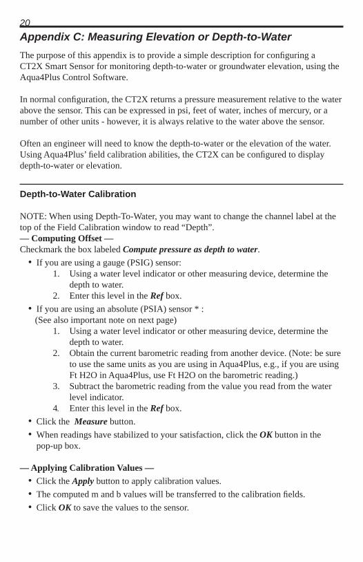
20Appendix C: Measuring Elevation or Depth-to-WaterThe purpose of this appendix is to provide a simple description for confi guring a CT2X Smart Sensor for monitoring depth-to-water or groundwater elevation, using the Aqua4Plus Control Software.
In normal confi guration, the CT2X returns a pressure measurement relative to the water above the sensor. This can be expressed in psi, feet of water, inches of mercury, or a number of other units - however, it is always relative to the water above the sensor.
Often an engineer will need to know the depth-to-water or the elevation of the water. Using Aqua4Plus’ fi eld calibration abilities, the CT2X can be confi gured to display depth-to-water or elevation.
Depth-to-Water Calibration
NOTE: When using Depth-To-Water, you may want to change the channel label at the top of the Field Calibration window to read “Depth”. — Computing Offset —Checkmark the box labeled Compute pressure as depth to water. • If you are using a gauge (PSIG) sensor: 1. Using a water level indicator or other measuring device, determine the depth to water. 2. Enter this level in the Ref box. • If you are using an absolute (PSIA) sensor * :
(See also important note on next page) 1. Using a water level indicator or other measuring device, determine the depth to water. 2. Obtain the current barometric reading from another device. (Note: be sure to use the same units as you are using in Aqua4Plus, e.g., if you are using Ft H2O in Aqua4Plus, use Ft H2O on the barometric reading.) 3. Subtract the barometric reading from the value you read from the water level indicator. 4 Enter this level in the Ref box. • Click the Measure button. • When readings have stabilized to your satisfaction, click the OK button in the pop-up box.
— Applying Calibration Values — • Click the Apply button to apply calibration values. • The computed m and b values will be transferred to the calibration fi elds. • Click OK to save the values to the sensor.

21Groundwater Elevation Calibration
— Computing Offset — • Place sensor in well • If you are using a gauge (PSIG) sensor: 1. Using a water level indicator or other measuring device, determine the depth to water. 2. Subtract this from the elevation at the top of the casing. 3. Enter this value in the Ref box for the fi rst point. • If you are using an absolute (PSIA) sensor * :
(See also important note below) 1. Using a water level indicator or other measuring device, determine the depth to water. 2. Obtain the current barometric reading from another device. (Note: be sure to use the same units as you are using in Aqua4Plus, e.g., if you are using Ft H2O in Aqua4Plus, use Ft H2O on the barometric reading.) 3. Subtract the water level reading (from step 1) from the elevation at the top of the casing. 4 Add the barometric reading from step 2 to the result of step 3. 5 Enter this level in the Ref box for the fi rst point. • Click fi rst Measure button. • When readings have stabilized to your satisfaction, click the OK button in the pop-up box.
— Applying Offset — • Click the Apply button to apply the offset. • The computed b value will be transferred to the calibration fi eld. • Click OK to save the value to the sensor.
IMPORTANT NOTE!
When taking readings with an absolute sensor: You will need to ADD the current barometric pressure to the sensor reading to get depth-to-water. You will need to SUBTRACT the current barometric pressure from the sensor reading to get elevation.

22Appendix D: Alternate Connection Options
Connecting via RS232 Serial Port
In its cabled confi guration, the CT2X cable is terminated with a weather-resistant connector. In its cableless confi guration, the CT2X is terminated with a weather-resistant connecter inside a screw-cap. Connect the weather-resistant connector to your computer’s serial port as shown below.
Connect the CT2X to your computer using an RS485/RS232 adapter and an interface cable.
Connecting with a USB/Serial Adapter
USB-to-Serial cables are readily available from many electronics and computer stores, as well as numerous sites on the Internet. INW has tested and recommends the Keyspan USA-19HS. It is available from INW as well as from many sites on the Internet. Install as follows:
• Plug into USB port.• Install the drivers provided with the particular unit.• Determine the port number to which the adapter is assigned.Right-click on My Computer.From the popup menu, select Manage to open the Computer Management
window.
PC or Laptop
Computer
RS485/RS232Adapter
Interface Cable
Weather-resistant Connectors Serial Port
CT2X
CT2XCable
Cabled Confi guration
RS485/RS232AdapterWeather-
resistant Connectors Serial Port
CT2XCableless Confi guration
Interface Cable
PC or Laptop
Computer
Screw-
CT2X
cap

23
Connection using a USB to Serial Adapter
On left panel, click on Device Manager.On right panel, double-click on Ports.A list of active COM ports will be displayed. Note the COM number
assigned to the adapter you just installed. For example: Close Manager.
• Connect to the sensor.• On the Aqua4Plus software, select the COM port noted above. (If you do not
see your new COM port in the dropdown box, open the Communications dialog box from the Options menu. Increase the Highest COM port number, up to a maximum of 15.)
Interface Cable
PC or LaptopComputer
USB PortUSB-to-Serial
Adapter
RS232/RS485Adapter
CT2X
CT2X Cable

24Appendix E: Reading the CT2X via Direct ReadWhile the CT2X comes with INW’s easy to use Aqua4Plus software, you can also use standard Modbus® RTU or SDI-12 equipment to easily take readings, so as to tie into your existing equipment or networks.
You may need to use Aqua4Plus to make a few settings, prior to directly reading the CT2X with your equipment. For one thing, you may want to change the units for returned values. If reading via Modbus, you may also need to set the baud rate. (You do not need to set the baud rate for SDI-12). These are described in the following sections.
For Modbus you must have CT2X fi rmware version 1.5 or higher. For SDI-12 you must have version 2.0 or higher.
Setting Units for Direct Read
The CT2X by default uses the following units: Temperature Degrees Celsius Conductivity uS/cm Pressure PSI Salinity PSU* TDS mg/L**Firmware version 2.8 or higher
If you have fi rmware 2.2 or later, you can select from a variety of units. If you want to change to different units, for example, degrees Fahrenheit for temperature or meters of water for pressure, set these units using Aqua4Plus, as shown below. Note: conductivity is always returned in uS/cm
• Connect your sensor to your computer.• Run Aqua4Plus (Be sure that you have Aqua4Plus version 1.8.5 or later. Also, be
sure you have the correct sensor fi rmware version, as described above.)• Scan for and click on your sensor.• Click on the Confi gure menu, and then select Advanced. • From the fl yout menu, select Direct Read Units. If you do not see this option, be
sure your sensor is running the correct fi rmware.• On the popup box, click the down-arrows next to the channel type you want to
change, and then select the units you want to. (Note, this does not affect the units used on the Aqua4Plus display. Refer to the Aqua4Plus software manual for details on using Aqua4Plus.)
• Click OK
Once set, these units are saved on the sensor and direct readings, either via Modbus or via SDI-12, will return values using these units. (Note: These settings do not affect the units used on the Aqua4Plus display. Refer to the Aqua4Plus software manual for details on using Aqua4Plus.)

25Reading Via Modbus® RTU
Setting Baud RateYour CT2X comes confi gured to communicate at 38,400 baud, with 8 data bits, one stop bit, and no parity. The sensor can also be set to 19,200 or 9600 baud, if needed for your application.
If needed, set your CT2X to the desired baud rate as follows:• Connect your sensor to your computer. (Refer to the Aqua4Plus or CT2X
Instruction manual for information on connecting your sensor to your computer.)• Run Aqua4Plus version 1.9.2 or later. • Scan for and click on your sensor.• If your sensor contains any data you want to keep, upload that data now.• Erase all sessions.• Click on the Confi gure menu, and then select Advanced.• From the fl yout menu, select Sensor Baud Rate. (You may be asked for a
password. The password is admin.) If you do not see the baud rate option, be sure your sensor is running version 1.5 or later fi rmware – see previous section.
• On the popup box, click the down-arrow and select the baud rate you need, and then click OK.
Once you have changed the baud rate on the sensor, you will not be able to talk to it with Aqua4Plus until you change the baud rate for Aqua4Plus, as follows:
• Click the Options menu, and then select Baud Rate.• On the popup box, click the down-arrow, select the baud rate you need, and then
click OK.The current Aqua4Plus baud rate is displayed in the lower right corner of the main Aqua4Plus window.
Taking MeasurementsReading RegistersRead measurements using Modbus function 03 – Read Holding Registers. Readings are located in two registers each, starting at address 62592. (CT2X register addressing is zero based, i.e., starts at zero. Check with your program and/or equipment documentation to determine what style of register addressing is required.)
Register Addresses for the TempHionTo Read: Specifi ed Address + 1 + 400,000 + 400,001 Temperature 62592 62593 462592 462593Conductivity (Linear) 62594 62595 462594 462595Conductivity (nLFn) 62596 62597 462596 462597Pressure 62598 62599 462598 462599Salinity* 62600 62601 462600 462601TDS* 62602 62603 462602 462603Sample Programs Visual Basic, Modpol Precision Digitalor Equipment Modbus Poll meters
*Firmware version 2.8 or higher

26Measurement TimingWhen you request a reading via Modbus, the sensor wakes up, returns the current values in the registers, and then starts taking new readings and updating the registers. After approximately 10 seconds, if no more readings have been requested, the sensor goes back to sleep.
Because of this, the fi rst reading you get will be old. If you are taking readings at intervals of less than 10 seconds, simply ignore the fi rst reading — all remaining readings will be current. On the other hand, if you are taking readings at intervals of greater than 10 seconds, take a reading, ignore it, wait one second, take another reading. Record this second reading.
Data FormatThe data is returned as 32-bit IEEE fl oating-point values, high word fi rst, also referred to as big-endian or fl oat inverse.
For further information and detailed Modbus examples, see INW application note, “Modbus Direct Read on AquiStar Smart Sensors” available from our web site at www.inwusa.com/technical-library/application-notes.

27
Reading Via SDI-12
AddressingDefault SDI-12 Address: 0
SDI-12 Command Nomenclature<a> = Sensor address{crc} = SDI-12 compatible 3-character CRC<cr> = ASCII carriage return character<lf> = ASCII line feed characterhighlighted values indicate variable data
SDI-12 Commands//*** Sensor Identifi cation<a>I! <a>13 INWUSA CT2X2.0ssssssssss<cr><lf> // note: 2.0 will change to refl ect current // fi rmware revision // ssssssssss = device serial #
//*** Acknowledge Active, Address Query<a>! <a><cr><lf>?! <a><cr><lf>
//*** Change Address <a>A<b>! <b><cr><lf> // change address from <a> to <b>
//*** Request measurement<a>M! <a>0024<cr><lf> // request all measurements<a>D0! <a>+22.0512+155.0127+155.2155+12.0512<cr><lf> // read: temperature, conductivity (linear– // uS/cm), conductivity (non-linear–uS/cm), // pressure (psi)
<a>M1! <a>0021<cr><lf> // request temperature measurement<a>D0! <a>+22.0512<cr><lf> // read temperature
<a>M2! <a>0021<cr><lf> // request linear conductivity measurement <a>D0! <a>+155.0127<cr><lf> // read conductivity (uS/cm)
<a>M3! <a>0021<cr><lf> // request non-linear conductivity measurement <a>D0! <a>+155.2155<cr><lf> // read conductivity (uS/cm)
<a>M4! <a>0021<cr><lf> // request pressure measurement<a>D0! <a>+12.0512<cr><lf> // read pressure (psi)
<a>M5! <a>0021<cr><lf> // request salinity measurement <a>D0! <a>20.7862<cr><lf> // read salinity (psu)
<a>M6! <a>0021<cr><lf> // request TDS measurement<a>D0! <a>14700.9<cr><lf> // read TDS (mg/L)

28
//*** Request measurement with CRC<a>MC! <a>0024<cr><lf> // request all measurements with CRC<a>D0! <a>+22.0512+155.0127+155.2155+12.0512{crc}<cr><lf> // read: temperature, conductivity (linear– // uS/cm), conductivity (non-linear–uS/cm), // pressure (psi)
<a>MC1! <a>0021<cr><lf> // request temperature measurement with CRC<a>D0! <a>+22.0512<cr><lf> // read temperature
<a>MC2! <a>0021<cr><lf> // request linear conductivity with CRC <a>D0! <a>+155.0127<cr><lf> // read conductivity (uS/cm)
<a>MC3! <a>0021<cr><lf> // request non-linear conductivity with CRC<a>D0! <a>+155.2155<cr><lf> // read conductivity (uS/cm)
<a>MC4! <a>0021<cr><lf> // request pressure measurement with CRC<a>D0! <a>+12.0512<cr><lf> // read pressure (psi)
<a>MC5! <a>0021<cr><lf> // request salinity measurement with CRC<a>D0! <a>20.7862<cr><lf> // read salinity (psu)
<a>MC6! <a>0021<cr><lf> // request TDS measurement with CRC<a>D0! <a>14700.9<cr><lf> // read TDS (mg/L)
//*** Concurrent measurement<a>C! <a>0024<cr><lf> // request all measurements<a>D0! <a>+22.0512+155.0127+155.2155+12.0512<cr><lf> // read: temperature, conductivity (linear– // uS/cm), conductivity (non-linear–uS/cm), // pressure (psi)
<a>C1! <a>0021<cr><lf> // request temperature measurement <a>D0! <a>+22.0512<cr><lf> // read temperature
<a>C2! <a>0021<cr><lf> // request linear conductivity measurement <a>D0! <a>+155.0127<cr><lf> // read conductivity (uS/cm)
<a>C3! <a>0021<cr><lf> // request non-linear conductivity measurement <a>D0! <a>+155.2155<cr><lf> // read conductivity (uS/cm)
<a>C4! <a>0021<cr><lf> // request pressure measurement <a>D0! <a>+12.0512<cr><lf> // read pressure (psi)
<a>C5! <a>0021<cr><lf> // request salinity measurement <a>D0! <a>20.7862<cr><lf> // read salinity (psu)
<a>C6! <a>0021<cr><lf> // request TDS measurement<a>D0! <a>14700.9<cr><lf> // read TDS (mg/L)

29//*** Concurrent measurement with CRC<a>CC! <a>0024<cr><lf> // request all measurements with CRC<a>D0! <a>+22.0512+155.0127+155.2155+12.0512{crc}<cr><lf> // read: temperature, conductivity (linear– // uS/cm), conductivity (non-linear–uS/cm), // pressure (psi)
<a>CC1! <a>0021<cr><lf> // request temperature measurement with CRC<a>D0! <a>+22.0512<cr><lf> // read temperature
<a>CC2! <a>0021<cr><lf> // request linear conductivity with CRC <a>D0! <a>+155.0127<cr><lf> // read conductivity (uS/cm)
<a>CC3! <a>0021<cr><lf> // request non-linear conductivity with CRC<a>D0! <a>+155.2155<cr><lf> // read conductivity (uS/cm)
<a>CC4! <a>0021<cr><lf> // request pressure measurement with CRC<a>D0! <a>+12.0512<cr><lf> // read pressure (psi)
<a>CC5! <a>0021<cr><lf> // request salinity measurement with CRC<a>D0! <a>20.7862<cr><lf> // read salinity (psu)
<a>CC6! <a>0021<cr><lf> // request TDS measurement with CRC<a>D0! <a>14700.9<cr><lf> // read TDS (mg/L)
For further information and SDI-12 examples, see the INW application note, “CT2X Interface Specifi cation (SDI-12)” available from our web site at www.inwusa.com/technical-library.

30
Appendix F: Reading Salinity NOTE: For greatest salinity accuracy, your CT2X should have the pressure option installed. If you do not have the pressure option, contact INW for further details.
Aqua4Plus
If you are only reading with Aqua4Plus: • Any fi rmware version higher than 2.0 will work. • We recommend Aqua4Plus version 1.9.2 or higher. • You will need to set the Temperature coeffi cient in the fi eld calibration window to zero (0) – it defaults to 2.1. • From Options Menu => Display Units, set Conductivity to PSU. • Salinity will now read on the Conductivity channel.
Via Modbus® or SDI-12
Firmware Compatibility • Firmware version 2.8 or higher and a sensor serial number higher than 2113500. This is fully compatible. • Firmware version 2.8 and a sensor serial number lower than 2113501: You will need to get a factory version of Aqua4Plus. (Contact INW.) We recommend using 1.9.2 or higher. Using this factory version, scan for your sensor. Open Confi gure => Factory settings => Sensor Range, and then click OK. (This will automatically set some internal values that are needed in the salinity calculations.) You will only have to do this once on a particular sensor. • Firmware 2.0 or above but less than 2.8: You will need return the sensor to INW for a fi rmware update. (While we can usually update fi rmware in the fi eld, in this instance it must be fl ashed at the factory.) • Firmware lower than 2.0: The fi rmware cannot be updated; the board will have to be replaced with a new generation board.
Setting Temperature Coeffi cientYou will need to set the Temperature coeffi cient in the fi eld calibration window to zero (0) – it defaults to 2.1.
Taking ReadingsRefer to Appendix E for details in using Modbus® or SDI-12 to take readings from the CT2X sensor.

31Appendix G: Battery Changing DetailsBattery Type: Two standard AA Alkaline batteries.
Because changing the batteries involves opening the water-tight seal, this must be done in a clean, dry environment to avoid contamination or moisture damage to the circuitry.
Tips
• Never place a tool on the sensor body, it is very thin and will deform causing leaks at o-ring seals and potentially crushing the circuit board!
• Always twist the sensor body off the top cap assembly rather than twisting the top cap assembly off of the sensor body.
• For cabled sensors, always clamp the sensor on the swaged area when applicable, the shoulder above it will allow you to press down without the worry of the sen-sor slipping out of the clamping device.
• If the sensor body is slippery or you are unable to grip it hard enough to twist, try a piece of rubber cabinet liner for additional friction.
Opening the Housing
There is a black, compressible square ring near the top of the sensor. This ring acts as a spring to lock the cable in. This needs to be compressed in order to allow removal of the top cap. Once this ring is compressed, a gentle counterclockwise twist is all that is needed to remove the cable from the sensor body. Compressing the black square ring does take force, twisting does not.
Cabled Sensor Cableless Sensor
Care must be taken to compress the black square ring before attempting to twist the housing. Forceful twisting of the housing can permantently damage the sensor.
Swage Knurling Black square ring Knurling Black square ring
HousingTop cap HousingTop cap

32Securing the sensor
In order to compress the black square ring, the sensor must be secured so that you can apply downward pressure to compress the ring. This can be done by holding in your hand, using a vise, or using pliers, as detailed below.
By Hand - cabled version only
1. Tightly grasp the top cap in one hand.2. Brace your hand against something such as a table or the ground. (Do not allow
the cable to be pinched against the brace.)
Continue to Removing the Housing on the next page.
With Vise - recommended method
Cabled Sensor
1. If possible, use a set of soft jaws as shown to prevent marring the surfaces of the top cap assembly.
2. Place the sensor in a vise clamping gently on the swaged area. You do not need to clamp the vise very hard.
Continue to Removing the Housing on the next page.
Cableless Sensor
1. If possible, use a set of soft jaws as shown to prevent marring the surfaces of the top cap assembly.
2. Remove the cableless top cap.3. Place the sensor in a vise clamping
gently on the knurled area. You do not need to clamp the vise very hard.
Continue to Removing the Housing on the next page.
Cabled Sensor - gripping on swage Cableless Sensor - gripping on knurled area

33With Pliers or Vise Grips - good for fi eld use
Removing the Housing
1. With your free hand, grasp the sensor body. Press down to compress the square ring. Twist gently. Once the body begins to twist, you can stop the compression action.
2. Finish gently twisting until the sensor body is removed. 3. Carefully disconnect the wiring connector inside from the circuit board in the
top cap.
Cabled Sensor
1. Grasp the pliers on the swaged area (do not grab the knurled diameter).
2. Find a hard edge and place the tips or side of the jaws of the pliers onto this edge as shown. This will allow you to press down with your weight to compress the square ring.
Continue to Removing the Housing below.
Cableless Sensor
1. Leave the cableless cap on in order to protect the pins inside.
2. Grasp the pliers on the knurled area tightly being careful to avoid grabbing the knurled cap.
3. Find a hard surface and place the cableless cap down onto it. This will allow you to press down with your weight to compress the square ring.
Continue to Removing the Housing below.
Cabled Sensor Cableless Sensor

34Replacing Batteries and Resealing Sensor
1. Gently pull wiring to one side in order to allow batteries to fall out. Shake gently if needed.
2. Replace batteries with button (+) facing open end.3. Reinstall wiring connector — it only goes in one way, so make sure not to
force it.
4. Hold the top cap assembly at 90° to the housing opening as shown. Depress the spring with your fi ngertip and tuck the wiring into the cutaway on the circuit board with your thumb to protect it while being installed back into the housing.
5. Rotate the top cap assembly into the opening in the housing being very careful not to nick or pinch any wires.
6. Gently press down until the assembly stops and then twist it into place. It will click in and decompress the gasket when it is fully engaged.
Pull wires gently to the side to allow battery removal.
Connector connected properly
Properly completed — black ring uncompressed
Wires tucked into slot and spring tucked into housing.
Push top cap in before twisting and locking.

35
Reordering Information
For sales & service offi ces, please contact:
INWwww.inwusa.com
800-776-9355

36LIMITED WARRANTY/DISCLAIMER - AquiStar® CT2X CONDUCTIVITY SENSORS
A. Seller warrants that products manufactured by Seller when properly installed, used and maintained with a properly installed desiccant tube, shall be free from defects in material and workmanship. Seller’s obligation under this warranty shall be limited to replacing or repairing the part or parts or, at Seller’s option, the products which prove defective in material or workmanship within ONE (1) year from the date of delivery, provided that Buyer gives Seller prompt notice of any defect or failure and satisfactory proof thereof. Any defective part or parts must be returned to Seller’s factory or to an authorized service center for inspection. Buyer will prepay all freight charges to return any products to Seller’s factory, or any other repair facility designated by Seller. Seller will deliver replacements for defective products to Buyer (ground freight prepaid) to the destination provided in the original order. Products returned to Seller for which Seller provides replacement under this warranty shall become the property of Seller.
This limited warranty does not apply to lack of performance caused by abrasive materials, cor-rosion due to aggressive fl uids, mishandling or misapplication. Seller’s obligations under this warranty shall not apply to any product which (a) is normally consumed in operation, or (b) has a normal life inherently shorter than the warranty period stated herein.
In the event that equipment is altered or repaired by the Buyer without prior written approval by the Seller, all warranties are void. Equipment and accessories not manufactured by the Seller are warranted only to the extent of and by the original manufacturer’s warranty.
THE FOREGOING WARRANTIES ARE IN LIEU OF ALL OTHER WARRANTIES, WHETH-ER ORAL, WRITTEN, EXPRESSED, IMPLIED OR STATUTORY. IMPLIED WARRANTIES OF FITNESS AND MERCHANTABILITY SHALL NOT APPLY. SELLER’S WARRANTY OBLIGATIONS AND BUYER’S REMEDIES THEREUNDER (EXCEPT AS TO TITLE) ARE SOLELY AND EXCLUSIVELY AS STATED HEREIN. IN NO CASE WILL SELLER BE LIABLE FOR CONSEQUENTIAL DAMAGES, LABOR PERFORMED IN CONNECTION WITH REMOVAL AND REPLACEMENT OF THE SENSOR SYSTEM, LOSS OF PRODUC-TION OR ANY OTHER LOSS INCURRED BECAUSE OF INTERRUPTION OF SERVICE. A NEW WARRANTY PERIOD SHALL NOT BE ESTABLISHED FOR REPAIRED OR REPLACED MATERIAL, PRODUCTS OR SUPPLIES. SUCH ITEMS SHALL REMAIN UNDER WARRANTY ONLY FOR THE REMAINDER OF THE WARRANTY PERIOD ON THE ORIGINAL MATERIALS, PRODUCTS OR SUPPLIES.
B. With respect to products purchased by consumers in the United States for personal use, the implied warranties including but not limited to the warranties of merchantability and fi tness for a particular purpose, are limited to twelve (12) months from the date of delivery.
Some states do not allow limitations on the duration of an implied warranty, so the above limita-tion may not apply to you. Similarly, some states do not allow the exclusion or limitation of consequential damages, so the above limitation or exclusion may not apply to you. This limited warranty gives you specifi c legal rights; however, you may also have other rights which may vary from state to state.

8902 122nd Avenue NEKirkland, WA 98033 USA 425-822-4434FAX 425-822-8384 / [email protected]
INW
©1997 - 2013 by Instrumentation Northwest, Inc. All rights reserved. Instrumentation Northwest and INW are trademarks registered with the U.S. Patent & Trademark Offi ce. Doc# 9B0830r9 12/19/2013 / PN 6D276-NI