AquaTroll 600 Public Interface...
81
Copyright © 2016 In-Situ Inc. This document is confidential and is the property of In-Situ Inc. Do not distribute without approval. AquaTroll 600 Public Interface Specification Revision: 1.01
Transcript of AquaTroll 600 Public Interface...

Copyright © 2016 In-Situ Inc. This document is confidential and is the property of In-Situ Inc. Do not distribute without approval.
AquaTroll 600
Public Interface Specification
Revision: 1.01

Copyright © 2016 In-Situ Inc. This document is confidential and is the property of In-Situ Inc. Do not distribute without approval.
Revision History
Date Revision Description 12/02/2015 1.00 Initial Release
12/14/2015 1.01 11.6 – Fixed calibration register size for 117 and 119.

Copyright © 2016 In-Situ Inc. This document is confidential and is the property of In-Situ Inc. Do not distribute without approval.
Table of Contents 1 Purpose ........................................................................................................................... 6
2 Overview ......................................................................................................................... 7 3 MODBUS Reserved Registers ...................................................................................... 8
3.1 Register Map Template Version .............................................................................. 8 3.2 Device Id .................................................................................................................. 8 3.3 Hardware Version .................................................................................................... 8 3.4 Max Data Logs ......................................................................................................... 8
3.5 Total Data Log Memory........................................................................................... 8 3.6 Total Battery Ticks ................................................................................................... 8
3.7 Last Battery Change ................................................................................................. 9 3.8 Device Commands ................................................................................................. 10 3.9 Current Time .......................................................................................................... 11 3.10 Device Status ........................................................................................................ 11
3.11 Used Battery Ticks ............................................................................................... 11 3.12 Serial Communication Configuration .................................................................. 12
3.12.1 Max Allowed Baud Rate Id ........................................................................... 12 3.12.2 Max Message/Response Size ......................................................................... 12 3.12.3 Device Address .............................................................................................. 12
3.13 Probe Connection Registers ................................................................................. 13 3.14 Max Sensor Connections...................................................................................... 13 3.15 Sensor Connection Status ..................................................................................... 13
3.16 Sensor Map Registers ........................................................................................... 13
3.17 Sensor Cache Timeout ......................................................................................... 14 3.18 Interface Configuration ........................................................................................ 14
4 Port Plug ....................................................................................................................... 15 4.1 Header Registers .................................................................................................... 15
5 Temperature Sensor .................................................................................................... 17 5.1 Header Registers .................................................................................................... 17
5.1.1 Warm-up Time ................................................................................................. 17 5.1.2 Fast Sample Rate.............................................................................................. 17
5.2 Parameter 1: Temperature ..................................................................................... 19 5.3 Calibration Registers .............................................................................................. 20
5.3.1 Temperature Calibration Procedure ................................................................. 20
6 Conductivity Sensor ..................................................................................................... 21 6.1 Header Registers .................................................................................................... 21
6.1.1 Warm-up Time ................................................................................................. 21 6.1.2 Fast Sample Rate.............................................................................................. 21
6.2 Parameter 1: Temperature ..................................................................................... 23 6.3 Parameter 2: Actual Conductivity ......................................................................... 24
6.4 Parameter 3: Specific Conductivity ...................................................................... 25 6.5 Parameter 4: Salinity ............................................................................................. 26

Copyright © 2016 In-Situ Inc. This document is confidential and is the property of In-Situ Inc. Do not distribute without approval.
6.6 Parameter 5: Total Dissolved Solids ..................................................................... 27 6.7 Parameter 6: Resistivity ........................................................................................ 28 6.8 Parameter 7: Density of Water .............................................................................. 29
6.9 Calibration Registers .............................................................................................. 30 6.9.1 Conductivity Calibration Procedure ................................................................ 31 6.9.2 Temperature Calibration Procedure ................................................................. 31
7 RDO Sensor .................................................................................................................. 33 7.1 Sensor Header Registers ........................................................................................ 33
7.1.1 Sensor Serial Number ...................................................................................... 33 7.1.2 Sensor Status .................................................................................................... 33 7.1.3 Last Factory Calibration .................................................................................. 34
7.1.4 Next Factory Calibration.................................................................................. 34 7.1.5 Warm-up Time ................................................................................................. 34 7.1.6 Fast Sample Rate.............................................................................................. 34
7.2 Parameter 1: DO Concentration ............................................................................ 35
7.3 Parameter 2: DO Saturation .................................................................................. 38 7.4 Parameter 3: Oxygen Partial Pressure ................................................................... 42
7.5 Calibration Registers .............................................................................................. 43 7.5.1 Automatic Salinity Correction ......................................................................... 43 7.5.2 Default Salinity Value...................................................................................... 43
7.5.3 100% Saturation Calibration Values ................................................................ 43 7.5.4 0% Saturation Calibration Values .................................................................... 44
7.5.5 Calibration Slope and Offset ............................................................................ 44
7.5.6 RDO Calibration Procedure ............................................................................. 45
8 pH/ORP Sensor ............................................................................................................ 47 8.1 Header Registers .................................................................................................... 47
8.1.1 Warm-up Time ................................................................................................. 47 8.1.2 Fast Sample Rate.............................................................................................. 48
8.2 Parameter 1: pH..................................................................................................... 49
8.3 Parameter 2: pH mV.............................................................................................. 50 8.4 Parameter 3: ORP mV ........................................................................................... 51 8.5 Calibration Registers .............................................................................................. 52
8.5.1 pH Measured Value ......................................................................................... 53 8.5.2 ORP Measured Value ...................................................................................... 53 8.5.3 pH Calibration Procedure ................................................................................ 54 8.5.4 ORP Calibration Procedure .............................................................................. 54
9 Turbidity Sensor .......................................................................................................... 55 9.1 Header Registers .................................................................................................... 55
9.1.1 Warm-up Time ................................................................................................. 55
9.1.2 Fast Sample Rate.............................................................................................. 55 9.2 Parameter 1: Turbidity .......................................................................................... 57 9.3 Parameter 2: Total Suspended Solids .................................................................... 58

Copyright © 2016 In-Situ Inc. This document is confidential and is the property of In-Situ Inc. Do not distribute without approval.
9.4 Calibration Registers .............................................................................................. 59 9.4.1 Turbidity Calibration Procedure ...................................................................... 59
10 Barometric Pressure Sensor ..................................................................................... 60 10.1 Header Registers .................................................................................................. 60 10.2 Parameter 1: Barometric Pressure ....................................................................... 61 10.3 Parameter 2: Battery Capacity ............................................................................ 63 10.4 Parameter 3: External Voltage ............................................................................ 64 10.5 Calibration Registers ............................................................................................ 65
10.5.1 Calibration Procedure .................................................................................... 65
11 Level Sensor ................................................................................................................ 66 11.1 Header Registers .................................................................................................. 66
11.1.1 Sensor Status .................................................................................................. 67 11.1.2 Warm-up Time ............................................................................................... 67 11.1.3 Fast Sample Rate............................................................................................ 67
11.2 Parameter 1: Pressure .......................................................................................... 68
11.3 Parameter 2: Depth .............................................................................................. 69 11.4 Parameter 3: Depth to Water ............................................................................... 70
11.5 Parameter 4: Surface Elevation ........................................................................... 71 11.6 Calibration Registers ............................................................................................ 72
11.6.1 Automatic Barometric Correction .................................................................. 72
11.6.2 Automatic Density Correction ....................................................................... 72 11.6.3 Specific Gravity ............................................................................................. 73
11.6.4 Depth Correction ............................................................................................ 73
11.6.5 Pressure Offset ............................................................................................... 73
11.6.6 Level Reference ............................................................................................. 74 11.6.7 Pressure Calibration Procedure ...................................................................... 74
11.6.8 DTW, Level Reference Procedure ................................................................. 76
12 Probe Registers .......................................................................................................... 77 12.1 Wiper Interval ...................................................................................................... 77
13 SDI-12 Interface ......................................................................................................... 78 13.1 Configuration File ................................................................................................ 78 13.2 Power Management .............................................................................................. 78
13.3 Basic Command Implementation ......................................................................... 78 13.4 Extended Command Implementation ................................................................... 81

Copyright © 2016 In-Situ Inc. This document is confidential and is the property of In-Situ Inc. Do not distribute without approval.
1 Purpose
This document is the high-level interface specification for the In-Situ AquaTroll 600
Probe (both non-vented and vented versions). It is an extension to the In-Situ System
Interface Specification, and defines the device-specific characteristics of the probe.

Copyright © 2016 In-Situ Inc. This document is confidential and is the property of In-Situ Inc. Do not distribute without approval.
2 Overview
The AquaTroll 600 Probe is a multi-parameter water quality probe with data logging. It
has integral depth and barometric pressure sensors and supports a variety of plug-in
sensors including, but not limited to, RDO, conductivity, temperature, turbidity, pH and
ORP. The probe supports the following interface standards.
1. MODBUS RS485. The device shall adhere to the specifications for probes and
sensors as described in the In-Situ System Interface specification and the
extensions described in this document.
2. MODBUS over Bluetooth. The device shall adhere to the specifications for
probes and sensors as described in the In-Situ System Interface specification and
the extensions described in this document.
3. SDI-12. The device shall adhere to the Serial Digital Interface Standard for
Microprocessor-Based Sensors, Version 1.3 dated September 17, 2002 and the
extensions to the specification described in this document.

Copyright © 2016 In-Situ Inc. This document is confidential and is the property of In-Situ Inc. Do not distribute without approval.
3 MODBUS Reserved Registers
The device shall implement the full reserved register set identified in the System
Interface Specifications. This section identifies device-specific values returned in the
reserved registers.
3.1 Register Map Template Version This register shall return the value 3.
3.2 Device Id The device id shall return 7 for the non-vented version.
The device id shall return 26 for the vented version.
The functionality of the two devices shall be identical except for the barometric pressure
measurement methodology.
3.3 Hardware Version The valid range for the device hardware version shall be 0 to 15.
Hardware Version Firmware Versions
2 1.00 – 1.XX
3.4 Max Data Logs The maximum number of data logs supported is 50.
3.5 Total Data Log Memory The total data log memory is 16,384,000 bytes.
3.6 Total Battery Ticks This register shall return 15,000,000, representing the battery capacity in microamp-
hours.
Copyright © 2016 In-Situ Inc. This document is confidential and is the property of In-Situ Inc. Do not distribute without approval.
3.7 Last Battery Change This register shall return the time of the last detected battery change. The time shall be
the internal UTC time with the current time offset correction applied. Batteries will be
considered changed under the following conditions.
The battery compartment is open and a set of alkaline batteries (defined as
measuring less than 3.5 volts) measures more than 200 millivolts different than
when last measured.
The battery compartment is open and a set of lithium batteries (defined as
measuring greater than 3.5 volts) measures more than 400 millivolts different than
when last measured.
The battery compartment is open and the battery type is changed as indicated by
transitioning between the above voltage ranges.
This register shall be read only.

Copyright © 2016 In-Situ Inc. This document is confidential and is the property of In-Situ Inc. Do not distribute without approval.
3.8 Device Commands The device-specific commands are specified below.
Id Name Access
Level
Description
0xD100 Operate Wiper 3 Manual wiper operation. Resets the wiper
interval. Exceptions:
0x94 – Wiper port open
0x93 – Wiper not installed (wiper plug)
0x95 – Wiper current overload
0x97 – Wiper operation timeout

Copyright © 2016 In-Situ Inc. This document is confidential and is the property of In-Situ Inc. Do not distribute without approval.
3.9 Current Time The current UTC time is kept to the nearest second. The fractions portion of the current
time register shall always return zero.
If the current UTC time is less than the manufacture date, indicating a loss of the time,
writing to the time register shall update the internal UTC time and set the offset
correction to zero. Otherwise, the internal UTC time shall not be modified by writing to
the register. A write shall cause an offset correction to the internal UTC time to be
calculated and stored. All subsequent reads and timestamps shall have the offset
correction applied to the internal UTC time.
3.10 Device Status The device will set bit 15 of the standard device status (physical port open warning) if the
wiper port or battery cover is open. The device supports the following device specific
status values.
Device Status Bit Values Bit Category Mask Description Cleared on Status Reset
16 Warning 0x00010000 Battery cover open No (note 1)
17 Warning 0x00020000 Wiper port open No (note 1, 2)
18 Status 0x00040000 Wiper installed No (note 2)
19 Warning 0x00080000 Wiper operation warning Yes
20 Status 0x00100000 Reserved No
21 Status 0x00200000 Reserved No
22 Status 0x00400000 Reserved No
23 Status 0x00800000 Reserved No
24 Status 0x01000000 Reserved No
25 Status 0x02000000 Reserved No
26 Status 0x04000000 Reserved No
27 Status 0x08000000 Reserved No
28 Status 0x10000000 Reserved No
29 Status 0x20000000 Reserved No
30 Status 0x40000000 Reserved No
31 Status 0x80000000 Reserved No
Note 1: These bits will also cause the standard port open status bit (bit 15) to be set.
Note 2: These bits are refreshed by reading the sensor connection status register.
3.11 Used Battery Ticks This register shall return the used battery capacity in microamp-hours.

Copyright © 2016 In-Situ Inc. This document is confidential and is the property of In-Situ Inc. Do not distribute without approval.
3.12 Serial Communication Configuration The standard communication control registers (9200 to 9209) shall apply to the RS485
interface. Operation of the Bluetooth interface shall not be affected by changes in these
registers. The RS485 interface shall support the communication configurations specified
in the table below.
Bits Description
0 Modbus Transmission Mode
0 = RTU (default)
1=ASCII
1,2 & 3 Baud Rate Id
0 = 9600
1 = 19200 (default)
2 = 38400
3 = 57600
4 Data Bits
0 = 7 data bits
1 = 8 data bits (default)
5,6 Parity Bits
0 = Even (default)
1 = Odd
2 = None
7 Stop Bits
0 = 1 Stop Bit (default)
1 = 2 Stop Bits
Note: 7 data bits is not a valid setting for Modbus RTU communication. If an attempt is
made to write RTU mode with 7 data bits, the device will return an exception with error
code 0x84. All other combinations of communication configurations shall be supported.
3.12.1 Max Allowed Baud Rate Id This register shall return a value of 3 (57600 baud).
3.12.2 Max Message/Response Size The device shall have a maximum message and response size of 1024 bytes. Reading
this value will return the maximum message size of the RS485 connection.
3.12.3 Device Address The sonde shall support a broadcast read of its device address register.
Copyright © 2016 In-Situ Inc. This document is confidential and is the property of In-Situ Inc. Do not distribute without approval.
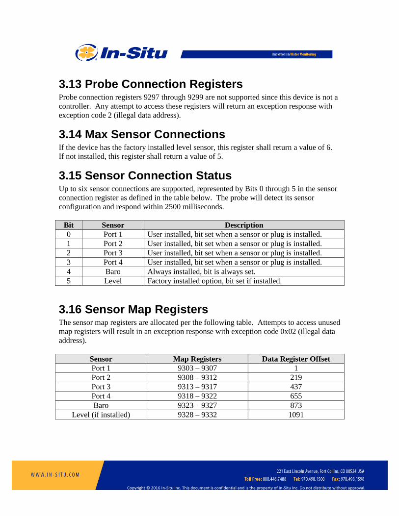
3.13 Probe Connection Registers Probe connection registers 9297 through 9299 are not supported since this device is not a
controller. Any attempt to access these registers will return an exception response with
exception code 2 (illegal data address).
3.14 Max Sensor Connections If the device has the factory installed level sensor, this register shall return a value of 6.
If not installed, this register shall return a value of 5.
3.15 Sensor Connection Status Up to six sensor connections are supported, represented by Bits 0 through 5 in the sensor
connection register as defined in the table below. The probe will detect its sensor
configuration and respond within 2500 milliseconds.
Bit Sensor Description
0 Port 1 User installed, bit set when a sensor or plug is installed.
1 Port 2 User installed, bit set when a sensor or plug is installed.
2 Port 3 User installed, bit set when a sensor or plug is installed.
3 Port 4 User installed, bit set when a sensor or plug is installed.
4 Baro Always installed, bit is always set.
5 Level Factory installed option, bit set if installed.
3.16 Sensor Map Registers The sensor map registers are allocated per the following table. Attempts to access unused
map registers will result in an exception response with exception code 0x02 (illegal data
address).
Sensor Map Registers Data Register Offset
Port 1 9303 – 9307 1
Port 2 9308 – 9312 219
Port 3 9313 – 9317 437
Port 4 9318 – 9322 655
Baro 9323 – 9327 873
Level (if installed) 9328 – 9332 1091

Copyright © 2016 In-Situ Inc. This document is confidential and is the property of In-Situ Inc. Do not distribute without approval.
3.17 Sensor Cache Timeout The default value for this register shall be 10000 milliseconds. The cache timer has a
resolution of one second. The cache timeout will be adjusted to be the smallest number
of whole seconds not less than the specified value.
3.18 Interface Configuration This register shall return a value of 21 (0x0015) indicating that SDI-12, Win-Situ logging
control, and a diagnostic log are supported.
A 4-20 mA current loop interface is not supported. Attempting to access current loop
configuration registers 9501 through 9507 will result in an exception response with
exception code 0x02 (illegal data address).

Copyright © 2016 In-Situ Inc. This document is confidential and is the property of In-Situ Inc. Do not distribute without approval.
4 Port Plug
A port plug is a user installed option and can appear in any sensor connection from 1 to 4
(bits 0 to 3 in the sensor connection status register). The corresponding sensor data offset
register points to the first register in the sensor data header block. All register values in
this section are offsets from that base value. A port plug does not support parameters.
Any attempt to access parameter registers will return an exception response with
exception code 2 (illegal data address).
4.1 Header Registers Register Size
(registers)
Mode &
Access Level
(R/W)
Data
Type
Description
0 1 R1 ushort Sensor Id = 20
1 2 R1 ulong Sensor serial number = 0
3 1 R1 16 bits Sensor status = 0
4 3 R1 time Last factory calibration = 0
7 3 R1 time Next factory calibration = 0
10 3 R1 time Last user calibration = 0
13 3 R1/W2 time Next user calibration = 0
16 1 R1 ushort Warm-up time = 0 milliseconds
17 1 R1 ushort Fast sample rate = 0 milliseconds
18 1 R1 ushort Number of sensor parameters (N) = 0
19 1 R1/W3 ushort Alarm/warning parameter number (1 – N, default = 1)
20 1 R1/W3 16 bits Alarm and warning enable bits (default = 0)
Bit 0 = High alarm enabled
Bit 1 = High warning enabled
Bit 2 = Low warning enabled
Bit 3 = Low alarm enabled
Bit 4 = Sensor calibration warning
21 2 R1/W3 float High alarm set value (default = 0.0)
23 2 R1/W3 float High alarm clear value (default = 0.0)
25 2 R1/W3 float High warning set value (default = 0.0)
27 2 R1/W3 float High warning clear value (default = 0.0)
29 2 R1/W3 float Low warning clear value (default = 0.0)
31 2 R1/W3 float Low warning set value (default = 0.0)
33 2 R1/W3 float Low alarm clear value (default = 0.0)
35 2 R1/W3 float Low alarm set value (default = 0.0)
Writing to the next user calibration register will return an exception response with
exception code 0x94 (sensor missing). Because a port plug provides no parameters,
writing to the alarm/warning parameter number registers will return an exception
response with exception code 0x84 (illegal field value). Alarm and warning set points

Copyright © 2016 In-Situ Inc. This document is confidential and is the property of In-Situ Inc. Do not distribute without approval.
can be read and written; however, their values have no affect.
Copyright © 2016 In-Situ Inc. This document is confidential and is the property of In-Situ Inc. Do not distribute without approval.
5 Temperature Sensor
The temperature sensor is a user installed option and can appear as any sensor connection
from 1 to 4 (bits 0 to 3 in the sensor connection status register). The corresponding
sensor data offset register points to the first register in the sensor data header block. All
register values in this section are offsets from that base value.
5.1 Header Registers Register Size
(registers)
Mode &
Access Level
(R/W)
Data
Type
Description
0 1 R1 ushort Sensor Id = 55
1 2 R1 ulong Sensor serial number
3 1 R1 16 bits Sensor status
4 3 R1/W4 time Last factory calibration
7 3 R1/W4 time Next factory calibration (0 = none required)
10 3 R1 time Last user calibration
13 3 R1/W2 time Next user calibration (0 = none required)
16 1 R1 ushort Warm-up time = 1100 milliseconds + dependencies
17 1 R1 ushort Fast sample rate = 1100 milliseconds
18 1 R1 ushort Number of sensor parameters (N) = 1
19 1 R1/W3 ushort Alarm/warning parameter number (1 – N, default = 1)
20 1 R1/W3 16 bits Alarm and warning enable bits (default = 0)
Bit 0 = High alarm enabled
Bit 1 = High warning enabled
Bit 2 = Low warning enabled
Bit 3 = Low alarm enabled
Bit 4 = Sensor calibration warning
21 2 R1/W3 float High alarm set value (default = 0.0)
23 2 R1/W3 float High alarm clear value (default = 0.0)
25 2 R1/W3 float High warning set value (default = 0.0)
27 2 R1/W3 float High warning clear value (default = 0.0)
29 2 R1/W3 float Low warning clear value (default = 0.0)
31 2 R1/W3 float Low warning set value (default = 0.0)
33 2 R1/W3 float Low alarm clear value (default = 0.0)
35 2 R1/W3 float Low alarm set value (default = 0.0)
5.1.1 Warm-up Time The warm-up time is the measurement time including the time necessary to power up the
sensors from their power off state and perform a wipe cycle.
5.1.2 Fast Sample Rate
Copyright © 2016 In-Situ Inc. This document is confidential and is the property of In-Situ Inc. Do not distribute without approval.
The fast sample rate is the measurement time when the sensors are already powered up
and a wipe cycle is not required.

Copyright © 2016 In-Situ Inc. This document is confidential and is the property of In-Situ Inc. Do not distribute without approval.
5.2 Parameter 1: Temperature Register Size
(registers)
Mode &
Access Level
(R/W)
Data
Type
Description
37 2 R1 float Measured value
39 1 R1 ushort Parameter Id = 1 (temperature)
40 1 R1/W2 ushort Units Id
1 = C (default)
2 = F
41 1 R1 ushort Data Quality Id
42 2 R1/W3 float Off line sentinel value (default = 0.0)
44 1 R1 16 bits Available Units = 0x0003 (3)
Temperature is factory calibrated in C. The measured temperature in °C (TM) is
calculated as:
TM = To + Tf
Where Tf is the factory calibrated temperature in °C and To is the user offset calibration.
Conversion to other units is as follows.
F = 1.8 * C + 32
If the sensor temperature measurement returns an error, the sonde will substitute its
internal temperature sensor value and set the data quality id to a warning. If the sonde
temperature measurement also generates an error, the sonde will use the sentinel value
and set the data quality id to an error.

Copyright © 2016 In-Situ Inc. This document is confidential and is the property of In-Situ Inc. Do not distribute without approval.
5.3 Calibration Registers Values in the calibration registers determine how sensor parameters are calculated.
Register Size
(registers)
Mode &
Access Level
(R/W)
Data
Type
Description
117 2 R1/W3 float Temperature Offset To in °C (default = 0.0)
5.3.1 Temperature Calibration Procedure The procedure to calibrate the temperature parameter shall be as follows.
1. Write the Calibration On command (0xE000) to the sensor command register.
Reading the temperature parameter in the calibration mode shall present the
temperature with the current user calibration applied (TM).
2. Instruct the user to place the temperature sensor in a water bath.
3. Read the temperature parameter TM and the external temperature reference TR.
4. Calculate the temperature offset as TO = TM – TR and write the offset to the
temperature offset register, all in the current units. Internally, the new offset is
added to the old offset. If the resulting offset is greater than +/- 1°C, the probe
will return an exception response with error code 0x97 indicating an invalid
calibration. If valid, the calibration is in effect immediately but not yet
permanently.
5. Write the Calibration Update command (0xE001) to the sensor command register.
The sensor sets the last user calibration date to the current date and sets the next
user calibration date to zero (none required).
6. Optionally, read the last user calibration time, add the next calibration interval,
and write the result to the next user calibration time register.
7. Write the Calibration Off command (0xE002) to the sensor command register to
place the sensor in normal operation.

Copyright © 2016 In-Situ Inc. This document is confidential and is the property of In-Situ Inc. Do not distribute without approval.
6 Conductivity Sensor
The conductivity sensor is a user installed option and can appear as any sensor
connection from 1 to 4 (bits 0 to 3 in the sensor connection status register). The
corresponding sensor data offset register points to the first register in the sensor data
header block. All register values in this section are offsets from that base value.
6.1 Header Registers Register Size
(registers)
Mode &
Access Level
(R/W)
Data
Type
Description
0 1 R1 ushort Sensor Id = 56
1 2 R1 ulong Sensor serial number
3 1 R1 16 bits Sensor status
4 3 R1 time Last factory calibration
7 3 R1/W4 time Next factory calibration (0 = none required)
10 3 R1/W4 time Last user calibration
13 3 R1/W2 time Next user calibration (0 = none required)
16 1 R1 ushort Warm-up time = 1100 milliseconds + dependencies
17 1 R1 ushort Fast sample rate = 1100 milliseconds
18 1 R1 ushort Number of sensor parameters (N) = 7
19 1 R1/W3 ushort Alarm/warning parameter number (1 – N, default = 1)
20 1 R1/W3 16 bits Alarm and warning enable bits (default = 0)
Bit 0 = High alarm enabled
Bit 1 = High warning enabled
Bit 2 = Low warning enabled
Bit 3 = Low alarm enabled
Bit 4 = Sensor calibration warning
21 2 R1/W3 float High alarm set value (default = 0.0)
23 2 R1/W3 float High alarm clear value (default = 0.0)
25 2 R1/W3 float High warning set value (default = 0.0)
27 2 R1/W3 float High warning clear value (default = 0.0)
29 2 R1/W3 float Low warning clear value (default = 0.0)
31 2 R1/W3 float Low warning set value (default = 0.0)
33 2 R1/W3 float Low alarm clear value (default = 0.0)
35 2 R1/W3 float Low alarm set value (default = 0.0)
6.1.1 Warm-up Time The warm-up time is the measurement time including the time necessary to power up the
sensors from their power off state, perform a wipe cycle, and correctly position the wiper.
6.1.2 Fast Sample Rate

Copyright © 2016 In-Situ Inc. This document is confidential and is the property of In-Situ Inc. Do not distribute without approval.
The fast sample rate is the measurement time when the sensors are already powered up
and the wiper is correctly positioned.

Copyright © 2016 In-Situ Inc. This document is confidential and is the property of In-Situ Inc. Do not distribute without approval.
6.2 Parameter 1: Temperature Register Size
(registers)
Mode &
Access Level
(R/W)
Data
Type
Description
37 2 R1 float Measured value
39 1 R1 ushort Parameter Id = 1 (temperature)
40 1 R1/W2 ushort Units Id
1 = C (default)
2 = F
41 1 R1 ushort Data Quality Id
42 2 R1/W3 float Off line sentinel value (default = 0.0)
44 1 R1 16 bits Available Units = 0x0003 (3)
Temperature is factory calibrated in C. The measured temperature in °C (TM) is
calculated as:
TM = To + Tf
Where Tf is the factory calibrated temperature in °C and To is the user offset calibration.
Conversion to other units is as follows.
F = 1.8 * C + 32
If the sensor temperature measurement returns an error, the sonde will substitute its
internal temperature sensor value and set the data quality id to a warning. If the sonde
temperature measurement also generates an error, the sonde will use the sentinel value
and set the data quality id to an error.

Copyright © 2016 In-Situ Inc. This document is confidential and is the property of In-Situ Inc. Do not distribute without approval.
6.3 Parameter 2: Actual Conductivity Register Size
(registers)
Mode &
Access Level
(R/W)
Data
Type
Description
45 2 R1 float Measured value, AC
47 1 R1 ushort Parameter Id = 9 (actual conductivity)
48 1 R1/W2 ushort Units Id
65 = microsiemens per centimeter (default)
66 = millisiemens per centimeter
49 1 R1 ushort Data Quality Id
50 2 R1/W3 float Off line sentinel value (default = 0.0)
52 1 R1 16 bits Available Units = 0x0003 (3)
Actual conductivity is factory calibrated in uS/cm. Conversion to other units is as
follows.
mS/cm = uS/cm / 1000

Copyright © 2016 In-Situ Inc. This document is confidential and is the property of In-Situ Inc. Do not distribute without approval.
6.4 Parameter 3: Specific Conductivity Register Size
(registers)
Mode &
Access Level
(R/W)
Data
Type
Description
53 2 R1 float Measured value, SC
55 1 R1 ushort Parameter Id = 10 (specific conductivity)
56 1 R1/W2 ushort Units Id
65 = microsiemens per centimeter (default)
66 = millisiemens per centimeter
57 1 R1 ushort Data Quality Id
58 2 R1/W3 float Off line sentinel value (default = 0.0)
60 1 R1 16 bits Available Units = 0x0003 (3)
The default units for specific conductivity are uS/cm. Conversion to other units is as
follows.
mS/cm = uS/cm / 1000
Specific conductivity is calculated from actual conductivity and temperature using the
following equation.
SC = AC * (0 + 1T + 2T2 + … + 7T
7) / (1 + (T-Tref))
Where Tref, , and 0-7 are specified in the sensor calibration registers. The factory
default coefficients shall calculate specific conductivity per Standard Methods 2510B.

Copyright © 2016 In-Situ Inc. This document is confidential and is the property of In-Situ Inc. Do not distribute without approval.
6.5 Parameter 4: Salinity Register Size
(registers)
Mode &
Access Level
(R/W)
Data
Type
Description
61 2 R1 float Measured value, S
63 1 R1 ushort Parameter Id = 12 (salinity)
64 1 R1/W2 ushort Units Id
97 = Practical Salinity Units PSU (default)
65 1 R1 ushort Data Quality Id
66 2 R1/W3 float Off line sentinel value (default = 0.0)
68 1 R1 16 bits Available Units = 0x0001 (1)
Salinity is calculated from actual conductivity and temperature using the following
equations as defined by Standard Methods 2520A with extensions for operation from 0 to
42 PSU.
S = a0 + a1Rt1/2 + a2Rt + a3Rt
3/2 + a4Rt2 + a5Rt
5/2
+ f(T) (b0 + b1Rt1/2 + b2Rt + b3Rt
3/2 + b4Rt2 + b5Rt
5/2)
-a0 / (1 + 1.5X + X2)
-b0 f(T) / (1 + Y1/2 + Y3/2)
Where:
Rt = AC / (r0 + r1T + r2T2 + r3T
3)
X = 400 Rt
Y = 100 Rt
f(T) = (T – 15) / (1 + 0.0162 (T – 15))
The following table defines the constants for the equations.
Constant Value Constant Value Constant Value
a0 0.0080 b0 0.0005 r0 29752.63
a1 -0.1692 b1 -0.0056 r1 830.5102
a2 25.3851 b2 -0.0066 r2 3.429338
a3 14.0941 b3 -0.0375 r3 -0.02193934
a4 -7.0261 b4 0.0636
a5 2.7081 b5 -0.0144

Copyright © 2016 In-Situ Inc. This document is confidential and is the property of In-Situ Inc. Do not distribute without approval.
6.6 Parameter 5: Total Dissolved Solids Register Size
(registers)
Mode &
Access Level
(R/W)
Data
Type
Description
69 2 R1 float Measured value, TDS
71 1 R1 ushort Parameter Id = 13 (TDS)
72 1 R1/W2 ushort Units Id
113 = parts per million
114 = parts per thousand (default)
73 1 R1 ushort Data Quality Id
74 2 R1/W3 float Off line sentinel value (default = 0.0)
76 1 R1 16 bits Available Units = 0x0003 (3)
The default units for TDS are ppt. Conversion to other units is as follows.
ppm = ppt * 1000
TDS is calculated from specific conductivity using the following equation.
TDS = CFTDS * SC
Where CFTDS is the TDS conversion factor in ppm units as specified in the sensor
calibration registers.
Copyright © 2016 In-Situ Inc. This document is confidential and is the property of In-Situ Inc. Do not distribute without approval.
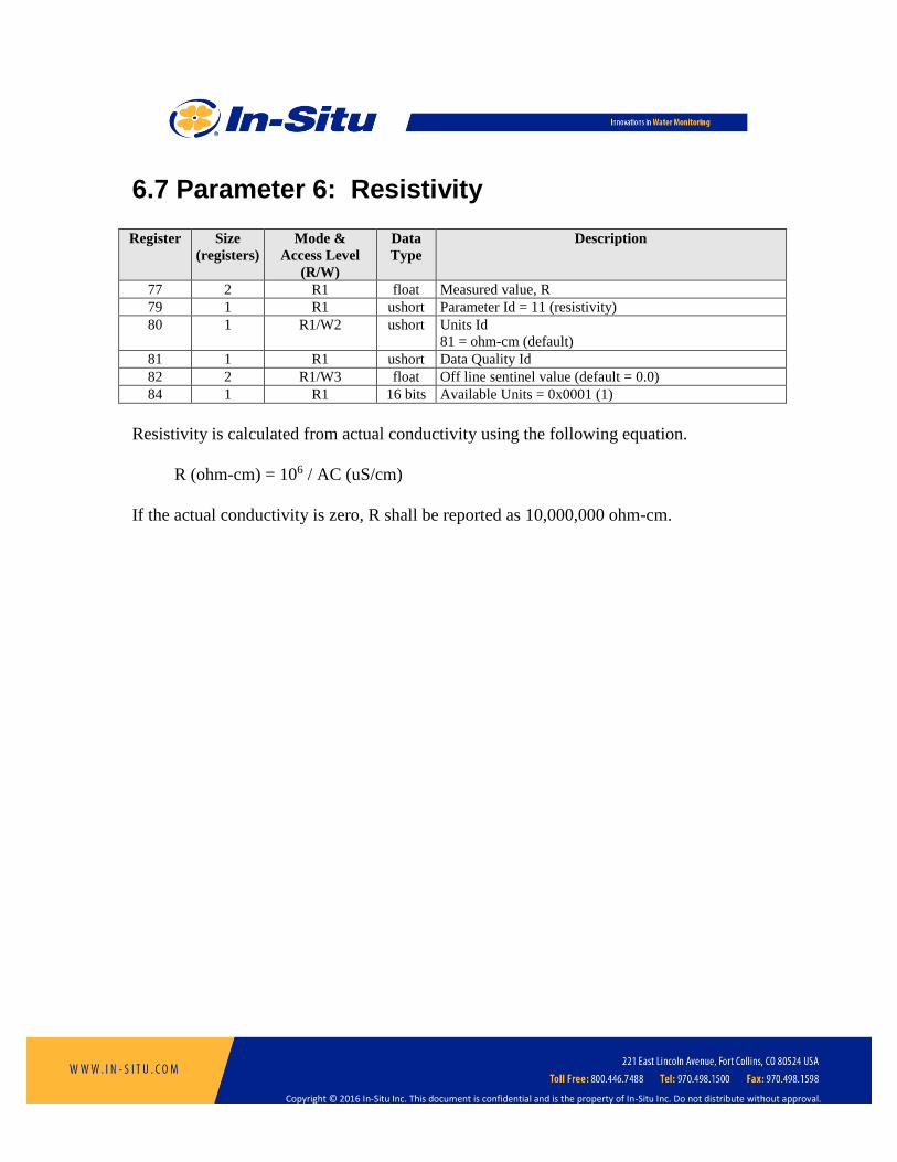
6.7 Parameter 6: Resistivity Register Size
(registers)
Mode &
Access Level
(R/W)
Data
Type
Description
77 2 R1 float Measured value, R
79 1 R1 ushort Parameter Id = 11 (resistivity)
80 1 R1/W2 ushort Units Id
81 = ohm-cm (default)
81 1 R1 ushort Data Quality Id
82 2 R1/W3 float Off line sentinel value (default = 0.0)
84 1 R1 16 bits Available Units = 0x0001 (1)
Resistivity is calculated from actual conductivity using the following equation.
R (ohm-cm) = 106 / AC (uS/cm)
If the actual conductivity is zero, R shall be reported as 10,000,000 ohm-cm.
Copyright © 2016 In-Situ Inc. This document is confidential and is the property of In-Situ Inc. Do not distribute without approval.
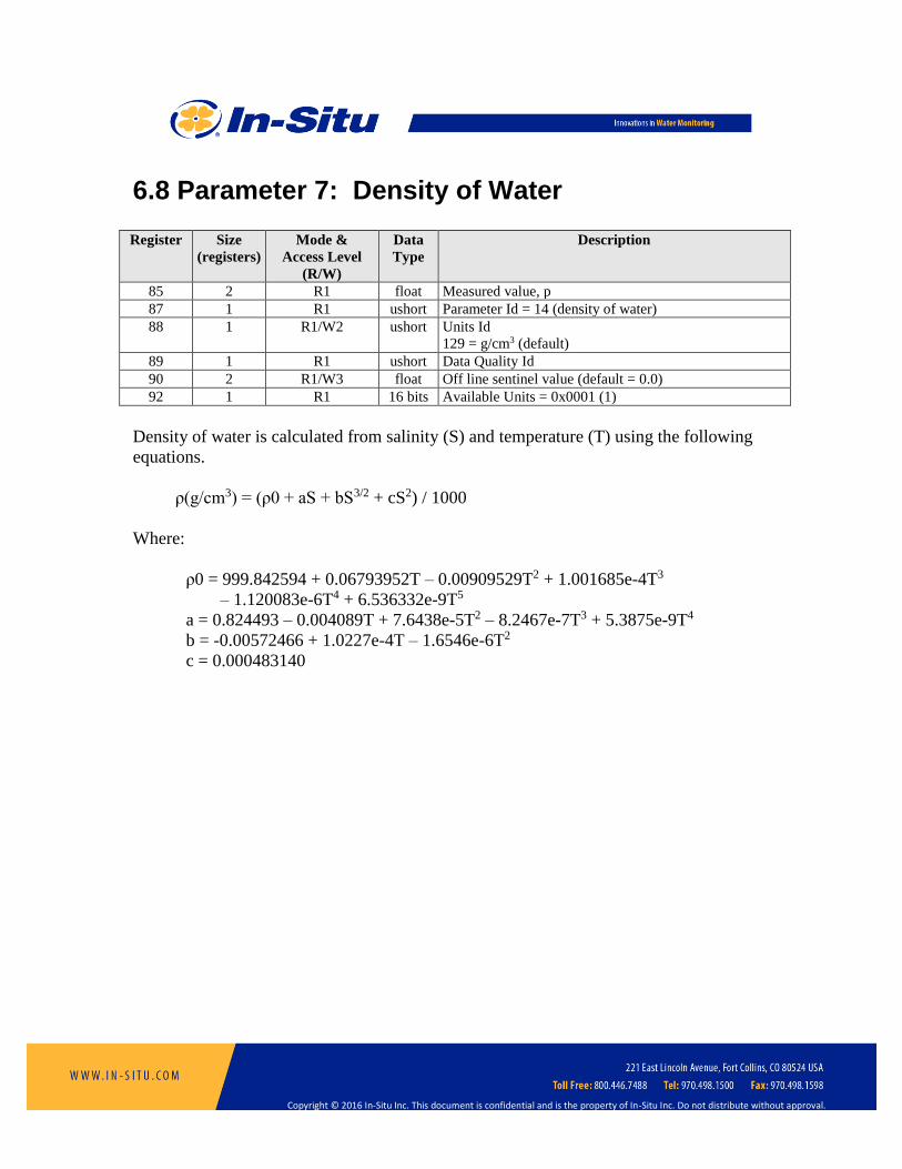
6.8 Parameter 7: Density of Water Register Size
(registers)
Mode &
Access Level
(R/W)
Data
Type
Description
85 2 R1 float Measured value, p
87 1 R1 ushort Parameter Id = 14 (density of water)
88 1 R1/W2 ushort Units Id
129 = g/cm3 (default)
89 1 R1 ushort Data Quality Id
90 2 R1/W3 float Off line sentinel value (default = 0.0)
92 1 R1 16 bits Available Units = 0x0001 (1)
Density of water is calculated from salinity (S) and temperature (T) using the following
equations.
ρ(g/cm3) = (ρ0 + aS + bS3/2 + cS2) / 1000
Where:
ρ0 = 999.842594 + 0.06793952T – 0.00909529T2 + 1.001685e-4T3
– 1.120083e-6T4 + 6.536332e-9T5
a = 0.824493 – 0.004089T + 7.6438e-5T2 – 8.2467e-7T3 + 5.3875e-9T4
b = -0.00572466 + 1.0227e-4T – 1.6546e-6T2
c = 0.000483140

Copyright © 2016 In-Situ Inc. This document is confidential and is the property of In-Situ Inc. Do not distribute without approval.
6.9 Calibration Registers Values in the calibration registers determine how sensor parameters are calculated.
Register Size
(registers)
Mode &
Access Level
(R/W)
Data
Type
Description
117 2 R1/W3 float Reference Temperature Tref in °C (default = 25)
119 2 R1/W3 float Alpha Coefficient (default = 0.0191)
121 2 R1/W3 float Beta Coefficient 0 (default = 1.0)
123 2 R1/W3 float Beta Coefficient 1 (default = 0.0)
125 2 R1/W3 float Beta Coefficient 2 (default = 0.0)
127 2 R1/W3 float Beta Coefficient 3 (default = 0.0)
129 2 R1/W3 float Beta Coefficient 4 (default = 0.0)
131 2 R1/W3 float Beta Coefficient 5 (default = 0.0)
133 2 R1/W3 float Beta Coefficient 6 (default = 0.0)
135 2 R1/W3 float Beta Coefficient 7 (default = 0.0)
137 2 R1/W3 float TDS Conversion Factor CFTDS in ppm (default = 0.65)
139 2 R1/W3 float Cell Constant, K (default = 1.0)
141 2 R1/W3 float Cell Offset, K0 (default = 0.0)
143 2 R1/W3 float Temperature Offset To in °C (default = 0.0)
Cell Offset and Cell Constant – These values are used to calibrate conductivity to user
standards. These registers shall only be able to be written when the sensor is in the
calibration mode. The probe will return exception 0x92 (invalid sensor mode) if an
attempt is made to write these registers when the calibration mode is off.
Actual conductivity (AC) is calculated as follows.
AC = K0 + K * ACf
Where ACf is the actual conductivity value computed using the factory calibrated cell
constant. For a single point calibration, K0 is set to zero.
Copyright © 2016 In-Situ Inc. This document is confidential and is the property of In-Situ Inc. Do not distribute without approval.
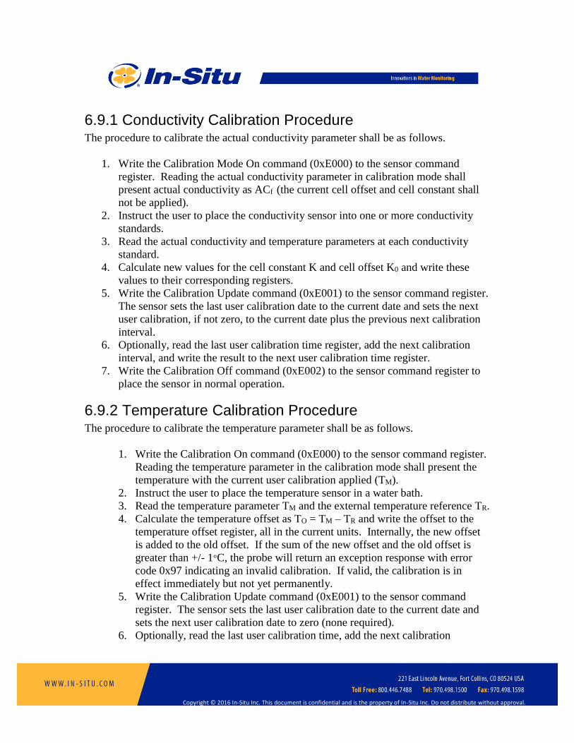
6.9.1 Conductivity Calibration Procedure The procedure to calibrate the actual conductivity parameter shall be as follows.
1. Write the Calibration Mode On command (0xE000) to the sensor command
register. Reading the actual conductivity parameter in calibration mode shall
present actual conductivity as ACf (the current cell offset and cell constant shall
not be applied).
2. Instruct the user to place the conductivity sensor into one or more conductivity
standards.
3. Read the actual conductivity and temperature parameters at each conductivity
standard.
4. Calculate new values for the cell constant K and cell offset K0 and write these
values to their corresponding registers.
5. Write the Calibration Update command (0xE001) to the sensor command register.
The sensor sets the last user calibration date to the current date and sets the next
user calibration, if not zero, to the current date plus the previous next calibration
interval.
6. Optionally, read the last user calibration time register, add the next calibration
interval, and write the result to the next user calibration time register.
7. Write the Calibration Off command (0xE002) to the sensor command register to
place the sensor in normal operation.
6.9.2 Temperature Calibration Procedure The procedure to calibrate the temperature parameter shall be as follows.
1. Write the Calibration On command (0xE000) to the sensor command register.
Reading the temperature parameter in the calibration mode shall present the
temperature with the current user calibration applied (TM).
2. Instruct the user to place the temperature sensor in a water bath.
3. Read the temperature parameter TM and the external temperature reference TR.
4. Calculate the temperature offset as TO = TM – TR and write the offset to the
temperature offset register, all in the current units. Internally, the new offset
is added to the old offset. If the sum of the new offset and the old offset is
greater than +/- 1°C, the probe will return an exception response with error
code 0x97 indicating an invalid calibration. If valid, the calibration is in
effect immediately but not yet permanently.
5. Write the Calibration Update command (0xE001) to the sensor command
register. The sensor sets the last user calibration date to the current date and
sets the next user calibration date to zero (none required).
6. Optionally, read the last user calibration time, add the next calibration

Copyright © 2016 In-Situ Inc. This document is confidential and is the property of In-Situ Inc. Do not distribute without approval.
interval, and write the result to the next user calibration time register.
7. Write the Calibration Off command (0xE002) to the sensor command register
to place the sensor in normal operation.
Copyright © 2016 In-Situ Inc. This document is confidential and is the property of In-Situ Inc. Do not distribute without approval.
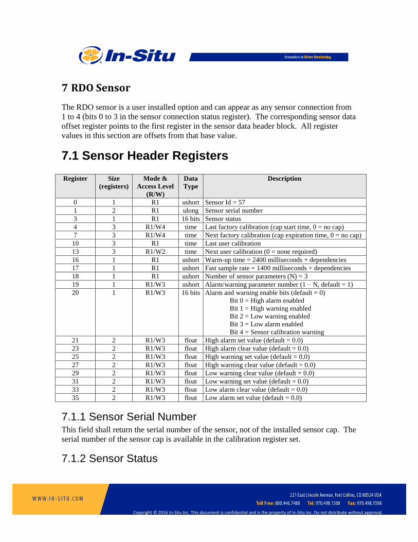
7 RDO Sensor
The RDO sensor is a user installed option and can appear as any sensor connection from
1 to 4 (bits 0 to 3 in the sensor connection status register). The corresponding sensor data
offset register points to the first register in the sensor data header block. All register
values in this section are offsets from that base value.
7.1 Sensor Header Registers Register Size
(registers)
Mode &
Access Level
(R/W)
Data
Type
Description
0 1 R1 ushort Sensor Id = 57
1 2 R1 ulong Sensor serial number
3 1 R1 16 bits Sensor status
4 3 R1/W4 time Last factory calibration (cap start time, 0 = no cap)
7 3 R1/W4 time Next factory calibration (cap expiration time, 0 = no cap)
10 3 R1 time Last user calibration
13 3 R1/W2 time Next user calibration (0 = none required)
16 1 R1 ushort Warm-up time = 2400 milliseconds + dependencies
17 1 R1 ushort Fast sample rate = 1400 milliseconds + dependencies
18 1 R1 ushort Number of sensor parameters (N) = 3
19 1 R1/W3 ushort Alarm/warning parameter number (1 – N, default = 1)
20 1 R1/W3 16 bits Alarm and warning enable bits (default = 0)
Bit 0 = High alarm enabled
Bit 1 = High warning enabled
Bit 2 = Low warning enabled
Bit 3 = Low alarm enabled
Bit 4 = Sensor calibration warning
21 2 R1/W3 float High alarm set value (default = 0.0)
23 2 R1/W3 float High alarm clear value (default = 0.0)
25 2 R1/W3 float High warning set value (default = 0.0)
27 2 R1/W3 float High warning clear value (default = 0.0)
29 2 R1/W3 float Low warning clear value (default = 0.0)
31 2 R1/W3 float Low warning set value (default = 0.0)
33 2 R1/W3 float Low alarm clear value (default = 0.0)
35 2 R1/W3 float Low alarm set value (default = 0.0)
7.1.1 Sensor Serial Number This field shall return the serial number of the sensor, not of the installed sensor cap. The
serial number of the sensor cap is available in the calibration register set.
7.1.2 Sensor Status
Copyright © 2016 In-Situ Inc. This document is confidential and is the property of In-Situ Inc. Do not distribute without approval.
Bit 9 of the sensor status register shall be set to indicate that the sensor cap is not
installed.
7.1.3 Last Factory Calibration This field shall return the start time of the installed sensor cap. If the cap has not been
used, the cap manufactured time shall be returned. The probe shall return zero if the
sensor cap is not installed.
7.1.4 Next Factory Calibration This field shall return the expiration time of the installed sensor cap. The probe shall
return zero if the sensor cap is not installed. The expiration calculation varies with the
supported cap type:
Classic Cap, Id 17: The value shall be the lesser of the cap manufactured time
plus 24 months, or the cap start time plus 12 months. The cap wear algorithm
shall be applied.
Fast Cap, Id 1: The value shall be the lesser of the cap manufactured time plus 36
months, or the cap start time plus 15 months. The cap wear algorithm shall not be
applied.
Test Cap, Id 65535: The value shall be calculated in the same manner as a fast
cap.
7.1.5 Warm-up Time The warm-up time is the measurement time including the time necessary to power up the
sensors from their power off state, perform a wipe cycle, correctly position the wiper,
read calibration data from a new cap, and read dependent sensor parameters (temperature,
salinity, barometric pressure).
7.1.6 Fast Sample Rate The fast sample rate is the measurement time when the sensors are already powered up.
The measurement time shall include the time necessary to reposition the wiper if needed,
and to read dependent sensor parameters.

Copyright © 2016 In-Situ Inc. This document is confidential and is the property of In-Situ Inc. Do not distribute without approval.
7.2 Parameter 1: DO Concentration DO concentration is calculated from the oxygen partial pressure and temperature using
settings contained in the sensor calibration registers.
Register Size
(registers)
Mode & Access
Level
(R/W)
Data
Type
Description
37 2 R1 float Measured value, C0
39 1 R1 ushort Parameter Id = 20
40 1 R1/W2 ushort Units Id
117 = mg/L (default)
118 = µg/L
41 1 R1 ushort Data Quality Id
42 2 R1/W3 float Off line sentinel value (default = 0.0)
44 1 R1 16 bits Available Units = 0x0030 (48)
If the parameter value is read when the sensor cap is not installed, it shall return the
sentinel value and a data quality id of 7 (sensor communication error).
DO concentration is internally calculated in mg/L. Conversion to other units is as
follows.
µg/L = 1000 * mg/L
Oxygen concentration C0 (mg/L) shall be calculated as follows:
CSMk
PEC )1(619988.31 0
0
0
0
Where:
0P is the partial pressure of O2 in atmospheres.
atmtorr PP 999876.759
Salinity correction:
ln Sc = S(B0 + B1Ts + B2Ts^2 + B3Ts^3) + C0S^2

Copyright © 2016 In-Situ Inc. This document is confidential and is the property of In-Situ Inc. Do not distribute without approval.
B0 = -6.246090E-003 B1 = -7.423444E-003 B2 = -1.048635E-002 B3 = -7.987907E-003 C0 = -4.679983E-007 Ts is the scaled temperature (t is the temperature in °C): Ts = ln [(298.15 – t) / (273.15 + t)] S is the salinity in psu
Henry’s constant:
T is temperature in degrees Kelvin.
Negative of the second pressure coefficient.
t is temperature in degrees C.
Density of Water:
T is in Kelvin
Molar mass of water.
0152.18M
References:
Benson and Krause, Jr.
The concentration and isotopic fractionation of gases dissolved in freshwater in
equilibrium with the atmosphere.
Limnol, Oceanogr, 25(4), 1980, 662-671
Gordon and Garcia

Copyright © 2016 In-Situ Inc. This document is confidential and is the property of In-Situ Inc. Do not distribute without approval.
Oxygen Solubility in Seawater: Better Fitting Equations
Limnol, Oceaongr, 37(6), 1992, 1307-1312
Copyright © 2016 In-Situ Inc. This document is confidential and is the property of In-Situ Inc. Do not distribute without approval.
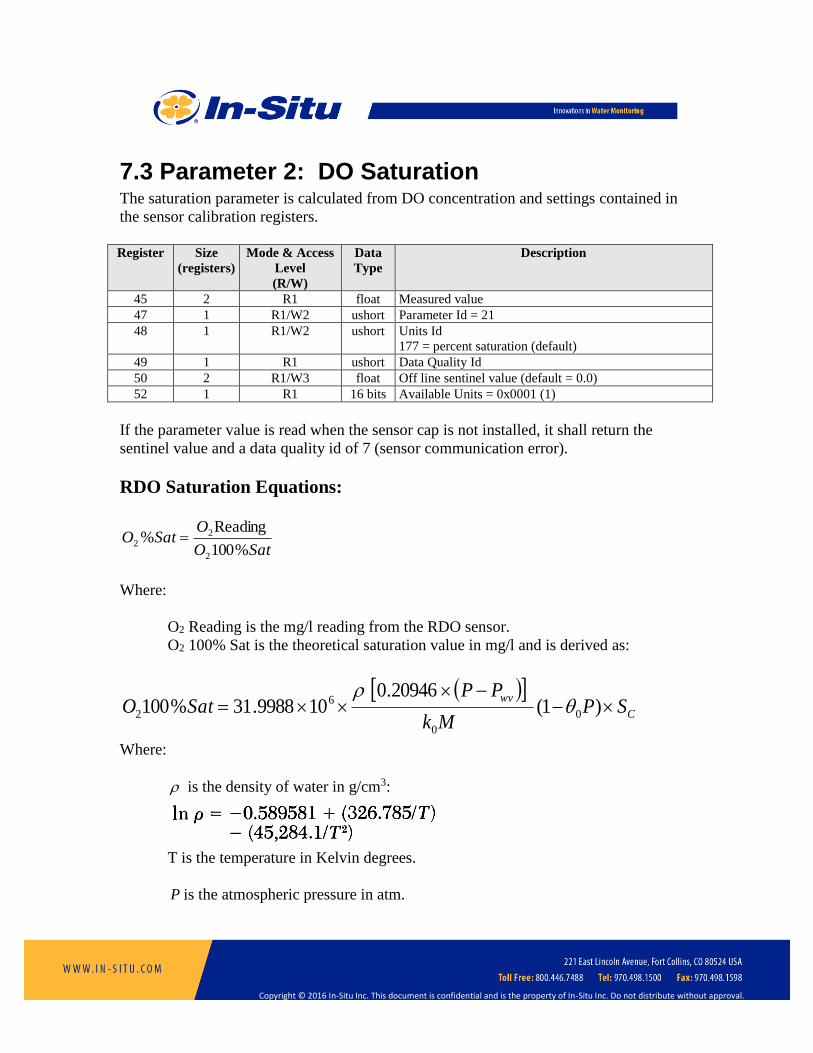
7.3 Parameter 2: DO Saturation The saturation parameter is calculated from DO concentration and settings contained in
the sensor calibration registers.
Register Size
(registers)
Mode & Access
Level
(R/W)
Data
Type
Description
45 2 R1 float Measured value
47 1 R1/W2 ushort Parameter Id = 21
48 1 R1/W2 ushort Units Id
177 = percent saturation (default)
49 1 R1 ushort Data Quality Id
50 2 R1/W3 float Off line sentinel value (default = 0.0)
52 1 R1 16 bits Available Units = 0x0001 (1)
If the parameter value is read when the sensor cap is not installed, it shall return the
sentinel value and a data quality id of 7 (sensor communication error).
RDO Saturation Equations:
SatO
OSatO
%100
Reading%
2
22
Where:
O2 Reading is the mg/l reading from the RDO sensor.
O2 100% Sat is the theoretical saturation value in mg/l and is derived as:
C
wvSP
Mk
PPSatO
)1(
20946.0109988.31%100 0
0
6
2
Where:
is the density of water in g/cm3:
T is the temperature in Kelvin degrees.
P is the atmospheric pressure in atm.

Copyright © 2016 In-Situ Inc. This document is confidential and is the property of In-Situ Inc. Do not distribute without approval.
Copyright © 2016 In-Situ Inc. This document is confidential and is the property of In-Situ Inc. Do not distribute without approval.
wvP is the partial pressure of water vapor at saturation in atm.
0k is Henry’s constant:
T is the temperature in Kelvin degrees.
M is the molar mass of water in g/mole
0152.18M
0 is the Negative of the second pressure coefficient.
t is temperature in degrees C.
CS is the salinity correction:
ln Sc = S(B0 + B1Ts + B2Ts^2 + B3Ts^3) + C0S^2 B0 = -6.246090E-003 B1 = -7.423444E-003 B2 = -1.048635E-002 B3 = -7.987907E-003 C0 = -4.679983E-007 Ts is the scaled temperature Ts = ln [(298.15 – t) / (273.15 + t)] where t is temperature in °C S is the salinity in psu
Per Standard Methods 4500-O(c), also see
Benson and Krause, Jr.
The concentration and isotopic fractionation of gases dissolved in freshwater in
equilibrium with the atmosphere.

Copyright © 2016 In-Situ Inc. This document is confidential and is the property of In-Situ Inc. Do not distribute without approval.
Limnol, Oceanogr, 25(4), 1980, 662-671
Copyright © 2016 In-Situ Inc. This document is confidential and is the property of In-Situ Inc. Do not distribute without approval.
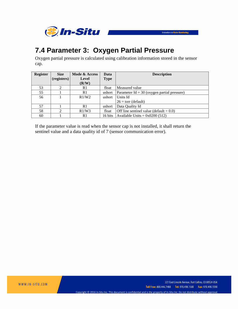
7.4 Parameter 3: Oxygen Partial Pressure Oxygen partial pressure is calculated using calibration information stored in the sensor
cap.
Register Size
(registers)
Mode & Access
Level
(R/W)
Data
Type
Description
53 2 R1 float Measured value
55 1 R1 ushort Parameter Id = 30 (oxygen partial pressure)
56 1 R1/W2 ushort Units Id
26 = torr (default)
57 1 R1 ushort Data Quality Id
58 2 R1/W3 float Off line sentinel value (default = 0.0)
60 1 R1 16 bits Available Units = 0x0200 (512)
If the parameter value is read when the sensor cap is not installed, it shall return the
sentinel value and a data quality id of 7 (sensor communication error).

Copyright © 2016 In-Situ Inc. This document is confidential and is the property of In-Situ Inc. Do not distribute without approval.
7.5 Calibration Registers Values in the calibration registers determine how sensor parameters are calculated.
Register Size
(registers)
Mode & Access
Level
(R/W)
Data
Type
Description
117 2 R1 float Installed cap type (0 = not installed)
119 2 R1 float Installed cap serial number (0 = not installed)
121 2 R1/W3 float Automatic salinity correction (default = 0)
123 2 R1/W3 float Default salinity value (PSU, default = 0.0)
125 2 R1/W3 float 100% saturation calibration reading (mg/L)
127 2 R1/W3 float 100% saturation temperature reading (°C)
129 2 R1/W3 float 100% saturation salinity value (PSU)
131 2 R1/W3 float 100% saturation barometric pressure (mbar)
133 2 R1/W3 float 0% saturation calibration reading (mg/L)
135 2 R1/W3 float 0% saturation temperature reading (°C)
137 2 R1/W3 float Calibration slope (default = 1.0)
139 2 R1/W3 float Calibration offset, mg/L (default = 0.0)
7.5.1 Automatic Salinity Correction Set this register to zero to disable automatic salinity correction. Set to one to enable
automatic correction. If disabled, the default salinity value is used to correct the oxygen
concentration value for salinity. If enabled, the salinity value is obtained from the
conductivity sensor.
7.5.2 Default Salinity Value The default salinity value is used to correct the oxygen concentration value for salinity
when automatic salinity correction is disabled. The allowed range of salinity is 0 to 42
PSU. If automatic salinity correction is enabled, the salinity value is obtained from the
conductivity sensor. If a conductivity sensor is not available, or a measurement error
occurs, the default salinity will be used and the measurement data quality will be reduced
to a warning.
7.5.3 100% Saturation Calibration Values These values represent the sensor conditions while the probe is in a 100% saturation
calibration environment. These are not measured values, they are written by the
controller during the calibration process.
Writes to these registers are only accepted if the probe is in the calibration mode. The
probe will return exception 0x92 (invalid sensor mode) if an attempt is made to write

Copyright © 2016 In-Situ Inc. This document is confidential and is the property of In-Situ Inc. Do not distribute without approval.
these registers when the calibration mode is off.
7.5.4 0% Saturation Calibration Values These values represent the sensor conditions while the probe is in a 0% saturation
calibration environment. These are not measured values, they are written by the
controller during the calibration process.
Writes to these registers are only accepted if the probe is in the calibration mode. The
probe will return exception 0x92 (invalid sensor) if an attempt is made to write these
registers when the calibration mode is off.
7.5.5 Calibration Slope and Offset These values represent the slope and offset that will be applied to the raw concentration
reading from the sensor to generate the final values reported by the sensor parameters.
Writes to these registers are only accepted if the probe is in the calibration mode. The
probe will return exception 0x92 (invalid sensor) if an attempt is made to write these
registers when the calibration mode is off. These registers may be written independently
of the normal internal calibration procedure.

Copyright © 2016 In-Situ Inc. This document is confidential and is the property of In-Situ Inc. Do not distribute without approval.
7.5.6 RDO Calibration Procedure The RDO sensor is calibrated using the following procedure.
1. Write the Calibration Mode On command (0xE000) to the sensor command
register.
2. If automatic barometric correction is enabled, prompt the user to “burp” the
battery pack cover to update the barometric pressure.
3. Prompt the user to place the probe in a 100% saturation environment.
4. Read the oxygen concentration and temperature parameters. When these values
have reached equilibrium, record them in their respective 100% saturation
calibration registers. Write the current salinity and barometric pressure readings
to their respective calibration registers.
5. Prompt the user to place the probe in a 0% saturation environment. When these
registers have reached equilibrium, record them in their respective 0% saturation
calibration registers. If a zero calibration is not to be performed, these registers
should be set to zero.
6. Write the Calibration Update command (0xE001) to the sensor command register.
The sensor will calculate a new slope and offset, will write the current time to the
last user calibration time register, and set the next user calibration time register, if
not zero, to the current date plus the previous next calibration interval. If the
concentrations at 100% and 0% saturation are equal the probe will return an
exception response with code 0x97 (invalid calibration) and not attempt to
compute a new slope and offset due to possible division by zero. If the slope does
not calculate between 0.85 and 1.20 inclusive, or the offset does not calculate
between -0.2 and +0.2 inclusive, the probe will return an exception response with
code 0x97 (invalid calibration). The slope and offset will be available for read
but will not be committed to flash.
7. Optionally, read the last user calibration time register, add the next calibration
interval, and write the result to the next user calibration time register.
8. Write the Calibration Mode Off command (0xE002) to the sensor command
register to place the sensor in normal operation. If the calibration mode is turned
off without a calibration update command, or the calibration command returned
an exception, the previous calibration shall be restored.

Copyright © 2016 In-Situ Inc. This document is confidential and is the property of In-Situ Inc. Do not distribute without approval.
Calibration calculations:
Calibrated Oxygen reading:
RURC OccO 2102
where:
RUZRUS
OO
SatOc
22
21
%100
RUZOcc 210
where:
SatO %1002 is the theoretical 100% saturation point.
RUSO2
is the un-calibrated reading at 100% saturation.
RUZO2 is the un-calibrated reading at 0% saturation.
References:
Standard Methods:
4500-0 C. Azide Modification

Copyright © 2016 In-Situ Inc. This document is confidential and is the property of In-Situ Inc. Do not distribute without approval.
8 pH/ORP Sensor
The pH/ORP sensor is a user installed option and can appear as any sensor connection
from 1 to 4 (bits 0 to 3 in the sensor connection status register). The corresponding
sensor data offset register points to the first register in the sensor data header block. All
register values in this section are offsets from that base value.
8.1 Header Registers Register Size
(registers)
Mode &
Access Level
(R/W)
Data
Type
Description
0 1 R1/W4 ushort Sensor Id = 58
1 2 R1/W4 ulong Sensor serial number
3 1 R1 16 bits Sensor status
4 3 R1/W4 time Last factory calibration
7 3 R1/W4 time Next factory calibration (0 = none required)
10 3 R1 time Last user calibration
13 3 R1/W2 time Next user calibration (0 = none required)
16 1 R1 ushort Warm-up time = 900 milliseconds + dependencies
17 1 R1 ushort Fast sample rate = 900 milliseconds + dependencies
18 1 R1 ushort Number of sensor parameters (N = 3)
19 1 R1/W3 ushort Alarm/warning parameter number (1 – N, default = 1)
20 1 R1/W3 16 bits Alarm and warning enable bits (default = 0)
Bit 0 = High alarm enabled
Bit 1 = High warning enabled
Bit 2 = Low warning enabled
Bit 3 = Low alarm enabled
Bit 4 = Sensor calibration warning
21 2 R1/W3 float High alarm set value (default = 0.0)
23 2 R1/W3 float High alarm clear value (default = 0.0)
25 2 R1/W3 float High warning set value (default = 0.0)
27 2 R1/W3 float High warning clear value (default = 0.0)
29 2 R1/W3 float Low warning clear value (default = 0.0)
31 2 R1/W3 float Low warning set value (default = 0.0)
33 2 R1/W3 float Low alarm clear value (default = 0.0)
35 2 R1/W3 float Low alarm set value (default = 0.0)
8.1.1 Warm-up Time The warm-up time is the measurement time including the time necessary to power up the
sensors from their power off state, perform a wipe cycle, correctly position the wiper, and
read dependent sensor parameters (temperature).

Copyright © 2016 In-Situ Inc. This document is confidential and is the property of In-Situ Inc. Do not distribute without approval.
8.1.2 Fast Sample Rate The fast sample rate is the measurement time when the sensors are already powered up.
The measurement time shall include the time necessary to reposition the wiper if needed,
and to read dependent sensor parameters.

Copyright © 2016 In-Situ Inc. This document is confidential and is the property of In-Situ Inc. Do not distribute without approval.
8.2 Parameter 1: pH Register Size
(registers)
Mode &
Access Level
(R/W)
Data
Type
Description
37 2 R1 float Measured value
39 1 R1 ushort Parameter Id = 17 (pH)
40 1 R1/W2 ushort Units Id
145 = pH (default)
41 1 R1 ushort Data Quality Id
42 2 R1/W3 float Off line sentinel value (default = 0.0)
44 1 R1 16 bits Available Units = 0x0001 (1)

Copyright © 2016 In-Situ Inc. This document is confidential and is the property of In-Situ Inc. Do not distribute without approval.
8.3 Parameter 2: pH mV Register Size
(registers)
Mode &
Access Level
(R/W)
Data
Type
Description
45 2 R1 float Measured value
47 1 R1 ushort Parameter Id = 18 (pH mV)
48 1 R1/W2 ushort Units Id
162 = mV (default)
49 1 R1 ushort Data Quality Id
50 2 R1/W3 float Off line sentinel value (default = 0.0)
52 1 R1 16 bits Available Units = 0x0002 (2)

Copyright © 2016 In-Situ Inc. This document is confidential and is the property of In-Situ Inc. Do not distribute without approval.
8.4 Parameter 3: ORP mV Register Size
(registers)
Mode &
Access Level
(R/W)
Data
Type
Description
53 2 R1 float Measured value
55 1 R1 ushort Parameter Id = 19 (ORP)
56 1 R1/W2 ushort Units Id
162 = mV (default)
57 1 R1 ushort Data Quality Id
58 2 R1/W3 float Off line sentinel value (default = 0.0)
60 1 R1 16 bits Available Units = 0x0002 (2)
Copyright © 2016 In-Situ Inc. This document is confidential and is the property of In-Situ Inc. Do not distribute without approval.
8.5 Calibration Registers Register Size
(registers)
Mode &
Access Level
(R/W)
Data
Type
Description
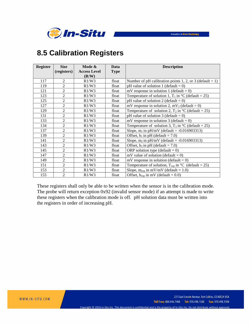
117 2 R1/W3 float Number of pH calibration points 1, 2, or 3 (default = 1)
119 2 R1/W3 float pH value of solution 1 (default = 0)
121 2 R1/W3 float mV response in solution 1 (default = 0)
123 2 R1/W3 float Temperature of solution 1, T1 in °C (default = 25)
125 2 R1/W3 float pH value of solution 2 (default = 0)
127 2 R1/W3 float mV response in solution 2, mV2 (default = 0)
129 2 R1/W3 float Temperature of solution 2, T2 in °C (default = 25)
131 2 R1/W3 float pH value of solution 3 (default = 0)
133 2 R1/W3 float mV response in solution 3 (default = 0)
134 2 R1/W3 float Temperature of solution 3, T3 in °C (default = 25)
137 2 R1/W3 float Slope, m1 in pH/mV (default = -0.016903313)
139 2 R1/W3 float Offset, b1 in pH (default = 7.0)
141 2 R1/W3 float Slope, m2 in pH/mV (default = -0.016903313)
143 2 R1/W3 float Offset, b2 in pH (default = 7.0)
145 2 R1/W3 float ORP solution type (default = 0)
147 2 R1/W3 float mV value of solution (default = 0)
149 2 R1/W3 float mV response in solution (default = 0)
151 2 R1/W3 float Temperature of solution, Torp in °C (default = 25)
153 2 R1/W3 float Slope, morp in mV/mV (default = 1.0)
155 2 R1/W3 float Offset, borp in mV (default = 0.0)
These registers shall only be able to be written when the sensor is in the calibration mode.
The probe will return exception 0x92 (invalid sensor mode) if an attempt is made to write
these registers when the calibration mode is off. pH solution data must be written into
the registers in order of increasing pH.

Copyright © 2016 In-Situ Inc. This document is confidential and is the property of In-Situ Inc. Do not distribute without approval.
8.5.1 pH Measured Value The measured value is derived from either one line (one or two point calibration) segment
or two line segments (three point calibration).
For one line segment:
pH = (T1K / TK) × m1 × mV + b1
For two line segments: mV > mV2: pH = (T1K / TK) × m1 × mV + b1
mV <= mV2: pH = (T2K / TK) × m2 × mV + b2
Where:
mV is the measured sensor millivolts
TK is the measured temperature in °K
T1K is the calibration temperature converted to °K. (T1K = T1 + 273.15)
T2K is the calibration temperature converted to °K. (T2K = T2 + 273.15)
m1 and b1 are slope and offset for segment one respectively
m2 and b2 are slope and offset for segment two respectively
pH is the calculated result
8.5.2 ORP Measured Value The measured value is derived as follows:
ORP = morp × mV + borp
Where:
mV is the measured sensor millivolts
morp and borp are slope and offset respectively
ORP is the calculated value

Copyright © 2016 In-Situ Inc. This document is confidential and is the property of In-Situ Inc. Do not distribute without approval.
8.5.3 pH Calibration Procedure The procedure to calibrate the pH parameter shall be as follows.
1. Write the Calibration Mode On command (0xE000) to the sensor command
register.
2. Instruct the user to place the pH sensor into one or more pH standards.
3. Read the pH mV and temperature parameters at each pH standard.
4. Calculate new pH calibration values and write these values to their corresponding
registers.
5. Write the Calibration Update command (0xE001) to the sensor command register.
The sensor sets the last user calibration date to the current date and sets the next
user calibration, if not zero, to the current date plus the previous next calibration
interval.
6. Optionally, read the last user calibration time register, add the next calibration
interval, and write the result to the next user calibration time register.
7. Write the Calibration Off command (0xE002) to the sensor command register to
place the sensor in normal operation.
8.5.4 ORP Calibration Procedure The procedure to calibrate the ORP parameter shall be as follows.
1. Write the Calibration Mode On command (0xE000) to the sensor command
register.
2. Instruct the user to place the ORP sensor into a standard.
3. Read the ORP mV and temperature parameters of the standard. Reading the ORP
parameter in the calibration will return raw ORP millivolts, without the current
calibration applied.
4. Calculate new ORP calibration values and write these values to their
corresponding registers.
5. Write the Calibration Update command (0xE001) to the sensor command register.
The sensor sets the last user calibration date to the current date and sets the next
user calibration, if not zero, to the current date plus the previous next calibration
interval.
6. Optionally, read the last user calibration time register, add the next calibration
interval, and write the result to the next user calibration time register.
7. Write the Calibration Off command (0xE002) to the sensor command register to
place the sensor in normal operation.

Copyright © 2016 In-Situ Inc. This document is confidential and is the property of In-Situ Inc. Do not distribute without approval.
9 Turbidity Sensor
The turbidity sensor is a user installed option and can appear as any sensor connection
from 1 to 4 (bits 0 to 3 in the sensor connection status register). The corresponding
sensor data offset register points to the first register in the sensor data header block. All
register values in this section are offsets from that base value.
9.1 Header Registers Register Size
(registers)
Mode &
Access Level
(R/W)
Data
Type
Description
0 1 R1/W4 ushort Sensor Id = 50
1 2 R1/W4 ulong Sensor serial number
3 1 R1 16 bits Sensor status
4 3 R1/W4 time Last factory calibration
7 3 R1/W4 time Next factory calibration (0 = none required)
10 3 R1 time Last user calibration
13 3 R1/W2 time Next user calibration (0 = none required)
16 1 R1 ushort Warm-up time = 800 milliseconds + dependencies
17 1 R1 ushort Fast sample rate = 800 milliseconds + dependencies
18 1 R1 ushort Number of sensor parameters (N = 2)
19 1 R1/W3 ushort Alarm/warning parameter number (1 – N, default = 1)
20 1 R1/W3 16 bits Alarm and warning enable bits (default = 0)
Bit 0 = High alarm enabled
Bit 1 = High warning enabled
Bit 2 = Low warning enabled
Bit 3 = Low alarm enabled
Bit 4 = Sensor calibration warning
21 2 R1/W3 float High alarm set value (default = 0.0)
23 2 R1/W3 float High alarm clear value (default = 0.0)
25 2 R1/W3 float High warning set value (default = 0.0)
27 2 R1/W3 float High warning clear value (default = 0.0)
29 2 R1/W3 float Low warning clear value (default = 0.0)
31 2 R1/W3 float Low warning set value (default = 0.0)
33 2 R1/W3 float Low alarm clear value (default = 0.0)
35 2 R1/W3 float Low alarm set value (default = 0.0)
9.1.1 Warm-up Time The warm-up time is the measurement time including the time necessary to power up the
sensors from their power off state, perform a wipe cycle, and correctly position the wiper.
9.1.2 Fast Sample Rate

Copyright © 2016 In-Situ Inc. This document is confidential and is the property of In-Situ Inc. Do not distribute without approval.
The fast sample rate is the measurement time when the sensors are already powered up
and the wiper is correctly positioned.
Copyright © 2016 In-Situ Inc. This document is confidential and is the property of In-Situ Inc. Do not distribute without approval.
9.2 Parameter 1: Turbidity Register Size
(registers)
Mode &
Access Level
(R/W)
Data
Type
Description
37 2 R1 float Measured value
39 1 R1 ushort Parameter Id = 25 (turbidity)
40 1 R1/W2 ushort Units Id
193 = FNU
194 = NTU (default)
41 1 R1 ushort Data Quality Id
42 2 R1/W3 float Off line sentinel value (default = 0.0)
44 1 R1 16 bits Available Units = 0x0003 (3)
Turbidity is internally calculated in NTU. The default units are NTU. Conversion to
other units is as follows:
FNU = NTU

Copyright © 2016 In-Situ Inc. This document is confidential and is the property of In-Situ Inc. Do not distribute without approval.
9.3 Parameter 2: Total Suspended Solids Register Size
(registers)
Mode &
Access Level
(R/W)
Data
Type
Description
45 2 R1 float Measured value
47 1 R1 ushort Parameter Id = 31 (TSS)
48 1 R1/W2 ushort Units Id
114 = parts per thousand
117 = mg/L (default)
49 1 R1 ushort Data Quality Id
50 2 R1/W3 float Off line sentinel value (default = 0.0)
52 1 R1 16 bits Available Units = 0x0012 (18)
The default units for TSS are mg/L. Conversion to other units is as follows.
ppt = 0.001 * mg/L
TSS is calculated from turbidity using the follow equation.
TSS = CFTSS * NTU
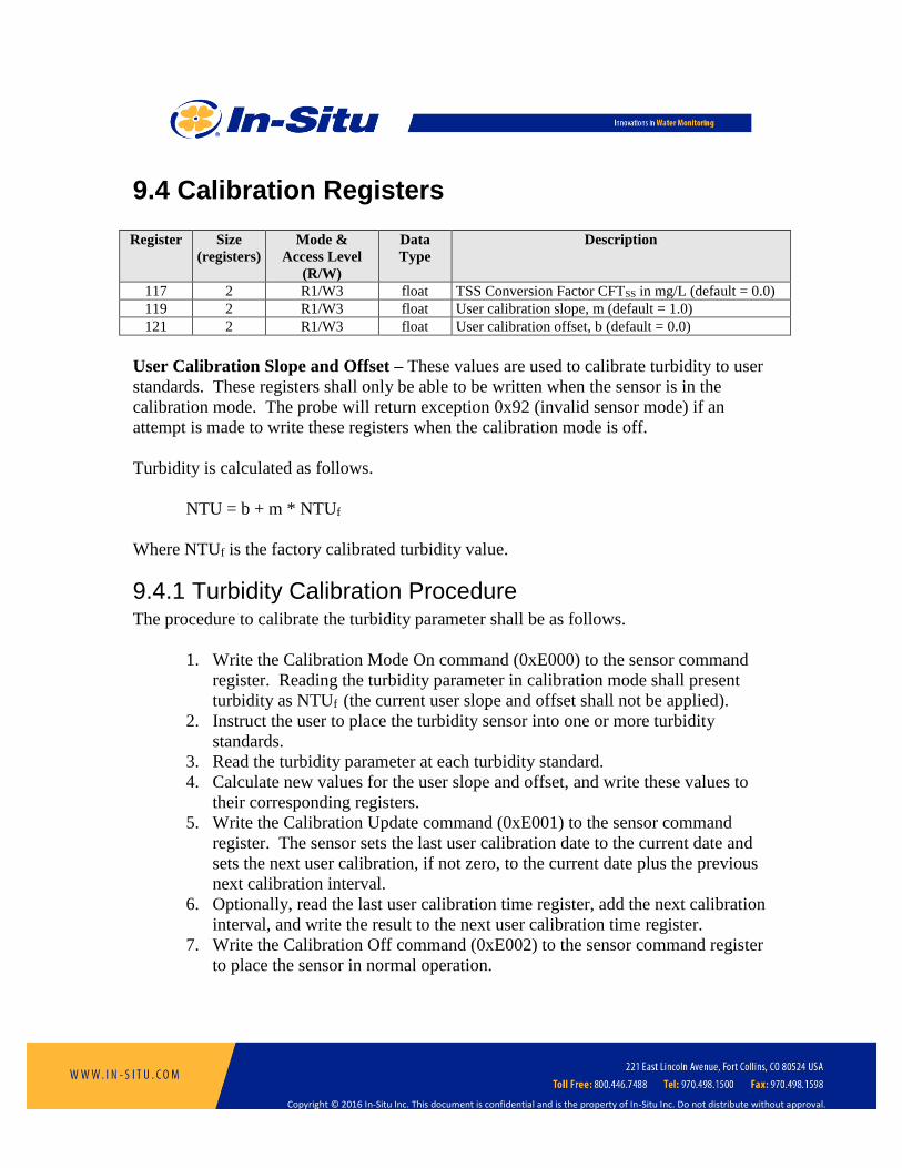
Copyright © 2016 In-Situ Inc. This document is confidential and is the property of In-Situ Inc. Do not distribute without approval.
9.4 Calibration Registers Register Size
(registers)
Mode &
Access Level
(R/W)
Data
Type
Description
117 2 R1/W3 float TSS Conversion Factor CFTSS in mg/L (default = 0.0)
119 2 R1/W3 float User calibration slope, m (default = 1.0)
121 2 R1/W3 float User calibration offset, b (default = 0.0)
User Calibration Slope and Offset – These values are used to calibrate turbidity to user
standards. These registers shall only be able to be written when the sensor is in the
calibration mode. The probe will return exception 0x92 (invalid sensor mode) if an
attempt is made to write these registers when the calibration mode is off.
Turbidity is calculated as follows.
NTU = b + m * NTUf
Where NTUf is the factory calibrated turbidity value.
9.4.1 Turbidity Calibration Procedure The procedure to calibrate the turbidity parameter shall be as follows.
1. Write the Calibration Mode On command (0xE000) to the sensor command
register. Reading the turbidity parameter in calibration mode shall present
turbidity as NTUf (the current user slope and offset shall not be applied).
2. Instruct the user to place the turbidity sensor into one or more turbidity
standards.
3. Read the turbidity parameter at each turbidity standard.
4. Calculate new values for the user slope and offset, and write these values to
their corresponding registers.
5. Write the Calibration Update command (0xE001) to the sensor command
register. The sensor sets the last user calibration date to the current date and
sets the next user calibration, if not zero, to the current date plus the previous
next calibration interval.
6. Optionally, read the last user calibration time register, add the next calibration
interval, and write the result to the next user calibration time register.
7. Write the Calibration Off command (0xE002) to the sensor command register
to place the sensor in normal operation.

Copyright © 2016 In-Situ Inc. This document is confidential and is the property of In-Situ Inc. Do not distribute without approval.
10 Barometric Pressure Sensor
The barometric pressure sensor is factory installed and always appears as sensor
connection 5 (bit 4 in the sensor connection status register). The corresponding sensor
data offset register points to the first register in the sensor data header block. All register
values in this section are offsets from that base value. Measuring the barometric sensor
does not trigger the wiper.
10.1 Header Registers Register Size
(registers)
Mode &
Access Level
(R/W)
Data
Type
Description
0 1 R1/W4 ushort Sensor Id = 59
1 2 R1 ulong Sensor serial number
3 1 R1 16 bits Sensor status
4 3 R1/W4 time Last factory calibration
7 3 R1/W4 time Next factory calibration (0 = none required)
10 3 R1 time Last user calibration
13 3 R1/W2 time Next user calibration (0 = none required)
16 1 R1 ushort Warm-up time = 300 milliseconds
17 1 R1 ushort Fast sample rate = 300 milliseconds
18 1 R1 ushort Number of sensor parameters (N) = 3
19 1 R1/W3 ushort Alarm/warning parameter number (1 – N, default = 1)
20 1 R1/W3 16 bits Alarm and warning enable bits (default = 0)
Bit 0 = High alarm enabled
Bit 1 = High warning enabled
Bit 2 = Low warning enabled
Bit 3 = Low alarm enabled
Bit 4 = Sensor calibration warning
21 2 R1/W3 float High alarm set value (default = 0.0)
23 2 R1/W3 float High alarm clear value (default = 0.0)
25 2 R1/W3 float High warning set value (default = 0.0)
27 2 R1/W3 float High warning clear value (default = 0.0)
29 2 R1/W3 float Low warning clear value (default = 0.0)
31 2 R1/W3 float Low warning set value (default = 0.0)
33 2 R1/W3 float Low alarm clear value (default = 0.0)
35 2 R1/W3 float Low alarm set value (default = 0.0)

Copyright © 2016 In-Situ Inc. This document is confidential and is the property of In-Situ Inc. Do not distribute without approval.
10.2 Parameter 1: Barometric Pressure Register Size
(registers)
Mode & Access
Level
(R/W)
Data
Type
Description
37 2 R1 float Measured value, PB
39 1 R1 ushort Parameter Id = 16 (barometric pressure)
40 1 R1/W2 ushort Units Id
17 = PSI (default)
19 = KPa
20 = bar
21 = mbar
22 = mmHg
24 = cmH2O
25 = in H2O
41 1 R1 ushort Data Quality Id
42 2 R1/W3 float Sentinel value (default = 14.696 PSI)
44 1 R1 16 bits Available Units = 0x01FD (509)
The measured barometric pressure (PB) is calculated as:
PB = BS + BO
Where BS is the factory calibrated barometric pressure and BO is the user offset
calibration, all in the current units.
Pressure is factory calibrated in mbar. Conversion to other units is as follows.
KPa = 6.894757 * PSI
bar = 0.06894757 * PSI
mbar = 68.94757 * PSI
mmHg = 51.71492 * PSI
inHg = 2.036021 * PSI
cmH2O = 70.30696 * PSI
inH2O = 27.67990 * PSI
In the non-vented unit, the barometric pressure is only measured when the battery
compartment is open. If a measurement is requested when the battery compartment is
closed, the last measurement taken with the battery compartment open is returned instead
of a live reading. If a barometric measurement has never been stored, the sensor will
return the sentinel value with an error data quality.
In the vented unit, barometric pressure can be measured at any time.

Copyright © 2016 In-Situ Inc. This document is confidential and is the property of In-Situ Inc. Do not distribute without approval.

Copyright © 2016 In-Situ Inc. This document is confidential and is the property of In-Situ Inc. Do not distribute without approval.
10.3 Parameter 2: Battery Capacity Register Size
(registers)
Mode & Access
Level
(R/W)
Data
Type
Description
45 2 R1 float Measured value
47 1 R1 ushort Parameter Id = 33 (battery capacity)
48 1 R1/W2 ushort Units Id
241 = % (default)
49 1 R1 ushort Data Quality Id
50 2 R1/W3 float Sentinel value (default = 0.0 %)
52 1 R1 16 bits Available Units = 0x0001 (1)
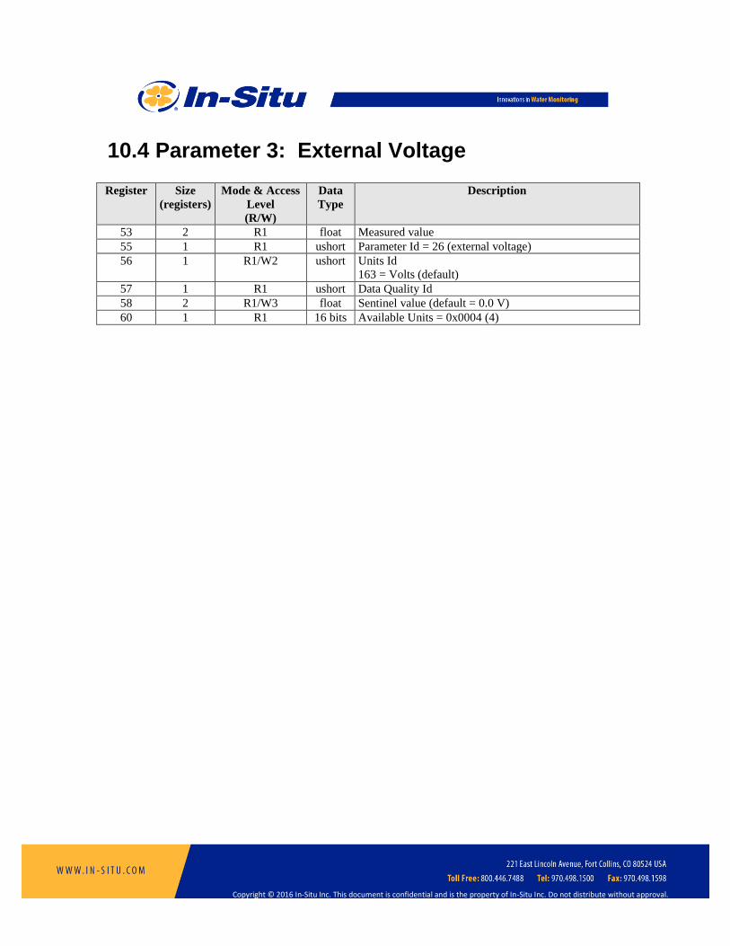
Copyright © 2016 In-Situ Inc. This document is confidential and is the property of In-Situ Inc. Do not distribute without approval.
10.4 Parameter 3: External Voltage Register Size
(registers)
Mode & Access
Level
(R/W)
Data
Type
Description
53 2 R1 float Measured value
55 1 R1 ushort Parameter Id = 26 (external voltage)
56 1 R1/W2 ushort Units Id
163 = Volts (default)
57 1 R1 ushort Data Quality Id
58 2 R1/W3 float Sentinel value (default = 0.0 V)
60 1 R1 16 bits Available Units = 0x0004 (4)

Copyright © 2016 In-Situ Inc. This document is confidential and is the property of In-Situ Inc. Do not distribute without approval.
10.5 Calibration Registers Values in the calibration registers determine how sensor parameters are calculated.
Register Size
(registers)
Mode & Access
Level
(R/W)
Data
Type
Description
117 2 R1/W3 float Barometric Offset, BO (default = 0.0)
10.5.1 Calibration Procedure The procedure to calibrate barometric pressure shall be as follows. The procedure is used
to match open air readings to a barometric reference.
1. Write the Calibration On command (0xE000) to the sensor command register.
Reading the pressure parameter in the calibration mode shall present the
barometric pressure with the current user calibration applied (PB).
2. For a non-vented unit, instruct the user to open the battery cover.
3. Read the barometric pressure parameter PB and external barometric pressure
reference BR. If the barometric pressure is read in calibration mode on a non-
vented unit with the battery cover closed, the sensor will return the sentinel value
with an error data quality.
4. Compute the barometric offset as BO = BR - PM and write the offset to the
barometric offset register, all in the current units. Internally, the new offset is
added to the old offset. If the resulting offset is greater than +/-10 mbar, the probe
will return an exception response with error code 0x97 indicating an invalid
calibration. If valid, the calibration is in effect immediately but not yet
permanently.
5. Write the Calibration Update command (0xE001) to the sensor command register.
The sensor sets the last user calibration date to the current date and sets the next
user calibration date, if not zero, to the current date plus the previous next
calibration interval. For a non-vented unit, saves the last calibrated reading as the
last measurement taken.
6. Optionally, read the last user calibration time, add the next calibration interval,
and write the result to the next user calibration time register.
7. Write the Calibration Off command (0xE002) to the sensor command register to
place the sensor in normal operation.

Copyright © 2016 In-Situ Inc. This document is confidential and is the property of In-Situ Inc. Do not distribute without approval.
11 Level Sensor
The level sensor is a factory installed option. If installed, it appears as sensor connection
6 (bit 5 in the sensor connection status register). The corresponding sensor data offset
register points to the first register in the sensor data header block. All register values in
this section are offsets from that base value. Measuring the level sensor does not trigger
the wiper unless a dependent parameter requires it.
11.1 Header Registers Register Size
(registers)
Mode &
Access Level
(R/W)
Data
Type
Description
0 1 R1/W4 ushort Sensor Id
0 = not installed
51 = 30 foot full-scale level, absolute pressure
52 = 100 foot full-scale level, absolute pressure
53 = 250 foot full-scale level, absolute pressure
54 = 650 foot full-scale level, absolute pressure
1 2 R1 ulong Sensor serial number
3 1 R1 16 bits Sensor status
4 3 R1 time Last factory calibration
7 3 R1 time Next factory calibration (0 = none required)
10 3 R1 time Last user calibration
13 3 R1/W2 time Next user calibration (0 = none required)
16 1 R1 ushort Warm-up time = 1000 milliseconds + dependencies
17 1 R1 ushort Fast sample rate = 1000 milliseconds + dependencies
18 1 R1 ushort Number of sensor parameters (N) = 4
19 1 R1/W3 ushort Alarm/warning parameter number (1 – N, default = 1)
20 1 R1/W3 16 bits Alarm and warning enable bits (default = 0)
Bit 0 = High alarm enabled
Bit 1 = High warning enabled
Bit 2 = Low warning enabled
Bit 3 = Low alarm enabled
Bit 4 = Sensor calibration warning
21 2 R1/W3 float High alarm set value (default = 0.0)
23 2 R1/W3 float High alarm clear value (default = 0.0)
25 2 R1/W3 float High warning set value (default = 0.0)
27 2 R1/W3 float High warning clear value (default = 0.0)
29 2 R1/W3 float Low warning clear value (default = 0.0)
31 2 R1/W3 float Low warning set value (default = 0.0)
33 2 R1/W3 float Low alarm clear value (default = 0.0)
35 2 R1/W3 float Low alarm set value (default = 0.0)

Copyright © 2016 In-Situ Inc. This document is confidential and is the property of In-Situ Inc. Do not distribute without approval.
11.1.1 Sensor Status Bit 15 of the sensor status register shall be set to indicate that the level parameters
provided (Depth, Depth to Water, and Surface Elevation) have fixed parameter ids.
11.1.2 Warm-up Time The warm-up time is the measurement time including the time necessary to power up the
sensors from their power off state, and read dependent sensor parameters (temperature,
density, barometric pressure).
11.1.3 Fast Sample Rate The fast sample rate is the measurement time when the sensors are already powered up
and includes the time necessary to read dependent sensor parameters.

Copyright © 2016 In-Situ Inc. This document is confidential and is the property of In-Situ Inc. Do not distribute without approval.
11.2 Parameter 1: Pressure Register Size
(registers)
Mode & Access
Level
(R/W)
Data
Type
Description
37 2 R1 float Measured value, P
39 1 R1 ushort Parameter Id = 2 (pressure)
40 1 R1/W2 ushort Units Id
17 = PSI (default)
19 = KPa
20 = bar
21 = mbar
22 = mmHg
24 = cmH2O
25 = in H2O
41 1 R1 ushort Data Quality Id
42 2 R1/W3 float Sentinel value (default = 0.0)
44 1 R1 16 bits Available Units = 0x01FD (509)
Pressure is factory calibrated in PSI. Conversion to other units is as follows.
KPa = 6.894757 * PSI
bar = 0.06894757 * PSI
mbar = 68.94757 * PSI
mmHg = 51.71492 * PSI
inHg = 2.036021 * PSI
cmH2O = 70.30696 * PSI
inH2O = 27.67990 * PSI
The calculation of pressure requires temperature. If a temperature sensor is not available,
the probe’s internal temperature will be used and the data quality will be a warning.

Copyright © 2016 In-Situ Inc. This document is confidential and is the property of In-Situ Inc. Do not distribute without approval.
11.3 Parameter 2: Depth The depth parameter is calculated from the pressure parameter using settings contained in
the sensor configuration registers.
Register Size
(registers)
Mode & Access
Level
(R/W)
Data
Type
Description
45 2 R1 float Measured value, D
47 1 R1/W2 ushort Parameter Id = 3 (depth)
48 1 R1/W2 ushort Units Id
33 = millimeters
34 = centimeters
35 = meters
37 = inches
38 = feet (default)
49 1 R1 ushort Data Quality Id
50 2 R1/W3 float Sentinel value (default = 0.0)
52 1 R1 16 bits Available Units = 0x0037 (55)
Depth is initially calculated in meters. Conversion to other units is as follows.
Millimeters = 1000 * meters
Centimeters = 100 * meters
Inches = 39.37008 * meters
Feet = 3.280840 * meters
Note that the units for depth, depth to water, and surface elevation are synchronized;
changing the units id for one will change the units id for all three.

Copyright © 2016 In-Situ Inc. This document is confidential and is the property of In-Situ Inc. Do not distribute without approval.
11.4 Parameter 3: Depth to Water The DTW parameter is calculated from the pressure parameter using settings contained in
the sensor configuration registers.
Register Size
(registers)
Mode & Access
Level
(R/W)
Data
Type
Description
53 2 R1 float Measured value, DTW
55 1 R1/W2 ushort Parameter Id = 4 (DTW)
56 1 R1/W2 ushort Units Id, same options as depth
57 1 R1 ushort Data Quality Id
58 2 R1/W3 float Sentinel value (default = 0.0)
60 1 R1 16 bits Available Units = 0x0037 (55)
DTW is initially calculated in meters. Conversion to other units is the same as depth.
Note that the units for depth, depth to water, and surface elevation are synchronized;
changing the units id for one will change the units id for all three.

Copyright © 2016 In-Situ Inc. This document is confidential and is the property of In-Situ Inc. Do not distribute without approval.
11.5 Parameter 4: Surface Elevation The surface elevation parameter is calculated from the pressure parameter using settings
contained in the sensor configuration registers.
Register Size
(registers)
Mode & Access
Level
(R/W)
Data
Type
Description
61 2 R1 float Measured value, L
63 1 R1/W2 ushort Parameter Id = 5 (level, elevation)
64 1 R1/W2 ushort Units Id, same options as depth
65 1 R1 ushort Data Quality Id
66 2 R1/W3 float Sentinel value (default = 0.0)
68 1 R1 16 bits Available Units = 0x0037 (55)
Surface elevation is initially calculated in meters. Conversion to other units is the same
as depth. Note that the units for depth, depth to water, and surface elevation are
synchronized; changing the units id for one will change the units id for all three.

Copyright © 2016 In-Situ Inc. This document is confidential and is the property of In-Situ Inc. Do not distribute without approval.
11.6 Calibration Registers Values in the calibration registers determine how sensor parameters are calculated.
Register Size
(registers)
Mode & Access
Level
(R/W)
Data
Type
Description
117 2 R1/W3 float Automatic barometric correction enable (default = 1.0)
119 2 R1/W3 float Automatic density correction enable (default = 0.0)
121 2 R1/W3 float Specific Gravity, SG (default = 1.0)
123 2 R1/W3 float Depth correction enable (default = 1.0)
125 2 R1/W3 float Pressure Offset, PO (default = 0.0)
127 2 R1/W3 float Level Reference, LR (default = 0.0)
129 2 R1/W3 float Pressure Reference, PR (default = 0.0)
11.6.1 Automatic Barometric Correction Set this register to zero to disable automatic barometric correction. Set to one to enable
automatic correction. If disabled, the measured pressure reading (PM) is simply the
pressure reading of the sensor (PS).
PM = PS
If automatic barometric correction is enabled, the probe’s barometric pressure value (PB)
is subtracted from the sensor pressure (PS) to generate the measured pressure reading.
PM = PS - PB
If an attempt is made to change this register while logging, the device will return an
exception response with error code 0xA0.
11.6.2 Automatic Density Correction Set this register to zero to disable automatic density correction. Set to one to enable
automatic correction. If disabled, pressures (PSI) are converted to depth (meters)
accounting for the specific gravity (SG) of the fluid according to the following equation.
Values shall be in the range 0.1 to 10.0 inclusive.
D(P) = (P * 0.70307) / SG
If automatic density correction is enabled, pressures (PSI) are converted to depth (meters)
accounting for the measured fluid density (ρ) according to the following equation. The
value contained in the specific gravity register is ignored.
Copyright © 2016 In-Situ Inc. This document is confidential and is the property of In-Situ Inc. Do not distribute without approval.
D(P) = (P * 0.70307) / ρ
If density is not available from a sensor on the probe, the specific gravity will be used
instead, and measurements will be flagged with a warning data quality. If an attempt is
made to change this register while logging, the device will return an exception response
with error code 0xA0.
11.6.3 Specific Gravity Values for specific gravity are allowed in the range 0.1 to 10.0 inclusive. If an attempt is
made to change this register while logging, the device will return an exception response
with error code 0xA0.
11.6.4 Depth Correction Set this register to zero to disable depth correction. Set to one to enable depth correction.
If enabled, the depth parameter is adjusted to present depth at the face of the sensors
instead of the pressure sensor. If an attempt is made to change this register while
logging, the device will return an exception response with error code 0xA0.
The equation to adjust the depth is:
Offset = L sin Ɵ, where Ɵ = tan-1(G) and G = gx / sqrt(gy2 + gz
2)
gx, gy, and gz are accelerometer outputs, L = 0.1916684 m (7.546 in)
Using trigonometric identities the offset can also be calculated as:
Offset = L (G / sqrt(1 + G2)), where G is defined above.
11.6.5 Pressure Offset The pressure offset (PO) is subtracted from the measured pressure reading (PM) to correct
for offset errors in the pressure sensor. This register shall only be able to be written when
the sensor is in the calibration mode. The probe will return exception 0x92 (invalid
sensor mode) if an attempt is made to write these registers when the calibration mode is
off. Master software must ensure that the pressure offset is written in the currently
selected units. This value shall be converted to the appropriate units when the Pressure
Units Id register is written. The measured pressure is presented as:
P = PM – PO

Copyright © 2016 In-Situ Inc. This document is confidential and is the property of In-Situ Inc. Do not distribute without approval.
11.6.6 Level Reference This value is used to reference a DTW or surface elevation reading to an independently
established value. This register shall only be able to be written when the sensor is in the
calibration mode. The probe will return exception 0x92 (invalid sensor mode) if an
attempt is made to write these registers when the calibration mode is off. Master
software must ensure that the level value is written in the currently selected depth/level
units. When this register is written, the device shall record the current pressure reading P
as the reference pressure PR in the currently selected pressure units. The following
equations shall be used to calculate level based on the level parameter id selection.
Parameter
Id
Description Equation
3 Depth D = D(P)
4 Depth to Water DTW = LR – D(P – PR)
5 Level, elevation L = LR + D(P – PR)
Pressure Reference – Master software may optionally overwrite the pressure reference
value recorded by the device when the Level Reference register is written. This register
shall only be able to be written when the sensor is in the calibration mode. The probe
will return exception 0x92 (invalid sensor mode) if an attempt is made to write these
registers when the calibration mode is off. Master software must ensure that the pressure
value is written in the currently selected units. This value shall be converted to the
appropriate units when the Pressure Units Id register is written.
11.6.7 Pressure Calibration Procedure The procedure to calibrate the pressure parameter shall be as follows. The procedure can
be used to zero the pressure reading, or to match open air readings to a barometric
reference (either internal or external).
1. Write the Calibration On command (0xE000) to the sensor command register.
Reading the pressure parameter in the calibration mode shall present the measured
pressure reading (PM) applying barometric compensation if enable, but without
applying the pressure offset.
2. Instruct the user to place the pressure sensor in open air.
3. Read the pressure parameter PS and pressure reference PR. PR can be assumed to
be zero, or can be the internal or an external barometric reference.
4. Compute the pressure offset as PO = PS – PR and write it to the pressure offset
register.
5. Write the Calibration Update command (0xE001) to the sensor command register.
The sensor sets the last user calibration date to the current date and sets the next
user calibration date, if not zero, to the current date plus the previous next
calibration interval.

Copyright © 2016 In-Situ Inc. This document is confidential and is the property of In-Situ Inc. Do not distribute without approval.
6. Optionally, read the last user calibration time, add the next calibration interval,
and write the result to the next user calibration time register.
7. Write the Calibration Off command (0xE002) to the sensor command register to
place the sensor in normal operation.
Copyright © 2016 In-Situ Inc. This document is confidential and is the property of In-Situ Inc. Do not distribute without approval.
11.6.8 DTW, Level Reference Procedure The procedure to reference the DTW or level parameter shall be as follows.
1. Write the Calibration On command (0xE000) to the sensor command register.
Reading the depth parameter in the calibration mode shall present depth using the
active pressure calibration and depth configuration settings to assist the user in
properly deploying the device.
2. Instruct the user to deploy the probe and to independently determine the reference
DTW or level (LR).
3. Write the new value of LR to the Level Reference register.
4. The sensor stores the current pressure P as PR.
5. Optionally, the master device can overwrite the pressure reference register with a
calculated value.
6. Write the Calibration Update command (0xE001) to the sensor command register.
The sensor sets the last user calibration date to the current date and sets the next
user calibration date, if not zero, to the current date plus the previous next
calibration interval.
7. Optionally, read the last user calibration time, add the next calibration interval,
and write the result to the next user calibration time register.
8. Write the Calibration Off command (0xE002) to the sensor command register to
place the sensor in normal operation.

Copyright © 2016 In-Situ Inc. This document is confidential and is the property of In-Situ Inc. Do not distribute without approval.
12 Probe Registers
Register Size
(registers)
Mode & Access
Level
(R/W)
Data
Type
Description
7000 1 R1 ushort Probe Register Map Template Version (1)
7001 1 R1 ushort External Power Voltage (millivolts)
7002 1 R1 ushort Internal Battery Voltage (millivolts)
7003 2 R1/W3 ulong Wiper Interval, 15 to 86400 seconds (default = 3600)
12.1 Wiper Interval This register determines shortest time interval (in seconds) that the wiper will be allowed
to operate. If the sample rate is faster than this value, whether by logging or live
readings, the wiper will only wipe at this interval. If the sample rate is longer than this
interval, the wiper will wipe at the sample rate. If a log or live reading is requested
within 15 seconds of the wiper interval, a wiper cycle will be triggered.
A wiper cycle consists of one complete revolution. Each revolution of the wiper will be
in the opposite direction. A clockwise revolution will be followed by a counterclockwise
revolution, etc.

Copyright © 2016 In-Situ Inc. This document is confidential and is the property of In-Situ Inc. Do not distribute without approval.
13 SDI-12 Interface
The device shall adhere to the Serial-Digital Interface Standard for Microprocessor-Based
Sensors, Version 1.3 dated September 17, 2002, and the extensions to the specification
identified in this document. This section identifies the device-specific implementation of
the standard.
13.1 Configuration File The device shall adhere to the specifications for writing and reading an SDI-12
configuration file as identified in the In-Situ System Interface Specification.
After the configuration file is written, sensors may be exchanged with sensors of the
same type, and do not need to stay in their original port.
13.2 Power Management When the device display turns off with external power connected, it enters a slightly
higher sleep power state that permits faster wake times. This can compensate for SDI-12
data recorders that may not meet the 100 ms wake delay required by the SDI-12
specification. If the display turns off with no external power connected, the device enters
its normal sleep mode for maximum battery life.
13.3 Basic Command Implementation The following table lists each basic SDI-12 command, its format, and the format of each
response.
Name Command Response
Address Query ?! a<CR><LF>
The wildcard address ‘?’ character is only supported for
the Address Query command. It shall be ignored as an
invalid address for all other commands.
Acknowledge Active a! a<CR><LF>
The device supports the basic address characters in the
range ‘0’ to ‘9’ and the extended address characters in
the ranges ‘A’ to ‘Z’ and ‘a’ to ‘z’. All other characters
are ignored as an invalid address. The default address is
‘0’.
Change Address aAb! b<CR><LF>
The device supports software changeable addresses.
Send Identification aI! a13IN-SITU AT600 vvv xxxxxx<CR><LF> or
a13IN-SITU AT600Vvvv xxxxxx<CR><LF>
vvv = device firmware version * 100 (120 = 1.20)
xxx = 6-digit device serial number with leading zeroes

Copyright © 2016 In-Situ Inc. This document is confidential and is the property of In-Situ Inc. Do not distribute without approval.
Name Command Response
Start Verification
Send Data
Additional Data
aV!
aD0!
aD1! … aD9!
a0033<CR><LF>
Three values are available for reading by the Send Data
command within 3 seconds. A service request
(a<CR><LF>) will be sent when the values are ready.
a+n+u+s<CR><LF>
n = lower 16 bits (0-65535) of the device status
u = upper 16 bits (0-65535) of the device status
s = lower 16 bits (0-65535) of the sensor connection
status register
a<CR><LF>
No values are returned after an additional data
command.
Start Measurement
Start Measurement CRC
Send Data
Additional Data
aM!
aMC!
aD0!
aD1! .. aD9!
a015n<CR><LF>
n parameters (1 to 9) will be available for reading by the
Send Data command within 15 seconds. A service
request (a<CR><LF>) will be sent when the parameters
are ready. The number of parameters returned and their
order is determined by the SDI-12 configuration file.
If the device is configured to output more than 9
parameters, only the first 9 parameters can be measured
by this command.
a<values><CR><LF> or
a<values><CRC><CR><LF>
At most 3 parameters are returned in a send data
command. If more than 3 parameters are available, they
are returned using the additional data command. A
value of -99999 indicates that an expected sensor was
missing.
a<values><CR><LF> or
a<values><CRC><CR><LF>
At most 3 parameters are returned per additional data
request. Additional Measurements
Additional with CRC
Send Data
Additional Data
aM1! … aM9!
aMC1! … aMC9!
aD0!
aD1! … aD9!
a0000<CR><LF> or
a015n<CR><LF>
If the device is configured to output more than 9
parameters, each additional measurement command
provides up to an addition 9 parameters.
a<values><CR><LF> or
a<values><CRC><CR><LF>
At most 3 parameters are returned per additional data
request.

Copyright © 2016 In-Situ Inc. This document is confidential and is the property of In-Situ Inc. Do not distribute without approval.
Name Command Response
Start Concurrent
Start Concurrent CRC
Send Data
Additional Data
aC!
aCC!
aD0!
aD1! … aD9!
a015nn<CR><LF>
nn parameters (1 to 20) will be available for reading by
the Send Data command within 15 seconds. No service
request will be sent when the parameters are ready. The
number of parameters returned and their order is
determined by the SDI-12 configuration file.
If the device is configured to output more than 9
parameters, only the first 9 parameters can be measured
by this command.
a<values><CR><LF> or
a<values><CRC><CR><LF>
At most 3 parameters are returned in a send data
command. If more than 3 parameters are available, they
are returned using the additional data command. A
value of -99999 indicates that an expected sensor was
missing.
a<values><CR><LF> or
a<values><CRC><CR><LF>
At most 3 parameters are returned per additional data
request.
Additional Concurrent
Additional with CRC
Send Data
Additional Data
aC1! … aC9!
aCC1! … aCC9!
aD0!
aD1! … aD9!
a00000<CR><LF> or
a015nn<CR><LF>
If the device is configured to output more than 9
parameters, each additional measurement command
provides up to an addition 9 parameters.
a<CR><LF> or
a<CRC><CR><LF>
a<values><CR><LF> or
a<values><CRC><CR><LF>
At most 3 parameters are returned per
additional data request. Continuous Measurement
Continuous with CRC
aR0! … aR9!
aRC0! … aRC9!
a<CR><LF>
No values are returned after a continuous measurement
command.

Copyright © 2016 In-Situ Inc. This document is confidential and is the property of In-Situ Inc. Do not distribute without approval.
13.4 Extended Command Implementation The device shall support the following extended SDI-12 commands.
Name Command Response
Auto Configure
Send Data
aXAC!
aD0!
a0051<CR><LF>
One result is available within 5 seconds for reading by
the Send Data command. Automatically creates an SDI-
12 configuration file consisting of all parameters of all
sensors beginning with port 1, up to a maximum of 30
parameters. A service request will be sent when the
results are ready.
a+p<CR><LF>
p = number of parameters configures, 0 = command
failed.
Set Factory Defaults
Send Data
aXFD!
aD0!
a0901<CR><LF>
One result is available within 90 seconds for reading by
the Send Data command. Restores all settings and
calibration values to their factory defaults. A service
request will be sent when the result is ready.
a+s<CR><LF>
s = command status, 1 = command successful, 0 =
command failed.
Communication
Diagnostics
Send Data
aXCD!
aD0!
a0012<CR><LF>
Two results are available within 1 second for reading by
the Send Data command. A service request will be sent
when the results are ready.
a+A+C<CR><LF>
A = contents of Modbus device address register 49200,
C = contents of Modbus serial communication
configuration register 49201.