AQUAIR 100 TM Operation Installation & Maintenance Manual ...
23
AQUAIR 100 TM Operation Installation & Maintenance Manual Manufactured by Ampair ®
Transcript of AQUAIR 100 TM Operation Installation & Maintenance Manual ...

AQUAIR 100
TM
Operation Installation & Maintenance Manual Manufactured by Ampair
®

Aquair 100TM Manual
© Ampair®, 2007 www.ampair.com Page 2 of 23
CONTENTS CONTENTS ................................................................................................................................2 SAFETY: READ BEFORE ASSEMBLING OR USING.................................................................3 Use..........................................................................................................................................3 Connection ..............................................................................................................................3 Protection ................................................................................................................................3
SYSTEM DESCRIPTION ............................................................................................................5 Introduction..............................................................................................................................5 The generator ..........................................................................................................................5 Water mode.............................................................................................................................5 Wind mode ..............................................................................................................................6
INSTALLATION...........................................................................................................................7 Water mode installation ...........................................................................................................7 Wind Mode Installation - Hoist In Rigging (HIR) .......................................................................9 Wind mode installation – Pole Mount .....................................................................................11 Wind mode installation – Stern Mount Kit...............................................................................13
ELECTRICAL INSTALLATION..................................................................................................14 CHARGE CONTROL REGULATION.........................................................................................15 Installation of charge control regulator ...................................................................................16
AQUAIR OPERATION & PERFORMANCE...............................................................................18 Operation – Water Mode:.......................................................................................................18 Operation – Wind Mode: ........................................................................................................18
MAINTENANCE AND SPARES ................................................................................................20 Inspection ..............................................................................................................................20 Major disassembly .................................................................................................................21
WARRANTY..............................................................................................................................23 SERVICING & REPAIRS...........................................................................................................23

Aquair 100TM Manual
© Ampair®, 2007 www.ampair.com Page 3 of 23
SAFETY: READ BEFORE ASSEMBLING OR USING Use
Avoid sailing in shallow water; through coral or weed; or near nets, lines, traps, pots, and buoys with the Aquair in water mode. When first using the Aquair in either wind or water mode it is advisable to do it in fairly calm weather and low wind or water speeds. WARNING: In either wind or water mode an Aquair is a piece of rotating equipment and
should be treated with care. Never allow it to become entangled in hair, clothing, or equipment. It is capable of causing GRAVE INJURY and should be treated with the same respect as a boat or aircraft propeller.
Connection
NEVER CONNECT WITHOUT RECTIFIERS
The generator must never be connected to a system without its rectifiers in circuit, to do so risks discharging the battery to which it is connected.
CORRECT CONNECTION
It is important to connect the system in such a way that the generator cannot feed any electrical load without the battery being connected. The generator output should therefore go to the battery side of any isolator switch. Failure to observe this point could place over-voltage on the system and damage sensitive electronic equipment.
Protection
PROTECTING THE SYSTEM
Do not omit the fitting of fuses, simple in-line fuse carriers maybe used in the battery line. Fuses = 10 Amp - 12V systems: 5 Amp - 24V systems
OBSERVE POLARITY
Reverse polarity will blow the battery fuse or destroy the rectifiers if no fuse is fitted. When wiring the system be aware that if the generator is connected to the battery REVERSE POLARITY the output rectifiers may be destroyed or the internal soldered connections to the brush holders may melt. Check and double-check polarity before final connection.
CORE 1 (formerly BROWN) = + Positive CORE 2 (formerly BLUE) = - Negative.
DISCONNECTING THE GENERATOR
When disconnecting the generator please be aware that when it is spinning, the output voltage, in the absence of a battery, will rise. This can give a mild electric shock to a person handling the connections.
WHEN TO FIT A REGULATOR
It is advisable to fit a voltage regulator if the Aquair is regularly left to charge batteries when insufficient or no loads are present. Under these conditions overcharge will slowly drive off the battery electrolyte, which, if not topped up, will eventually damage the batteries.
CAUTION
When planning your installation, observe the following: 1. Avoid operating the Aquair with the tow rope skipping. If it is skipping the tow rope will
constantly jerk both the generator and mounting. If the boat is going this fast use the coarse turbine.

Aquair 100TM Manual
© Ampair®, 2007 www.ampair.com Page 4 of 23
2. Regularly inspect a newly installed system to check that all is well. Do not limit this to monitoring the electrical output, but also check for smooth mechanical operation. Any defects need to be remedied immediately.
3. Finally, in water mode, connect a safety line (well clear of the propeller) to save the generator should it become detached from its mounting.

Aquair 100TM Manual
© Ampair®, 2007 www.ampair.com Page 5 of 23
SYSTEM DESCRIPTION Introduction
The Aquair 100 is a dual capability generator, which can be either water or wind driven. It is capable of supplying up to 100 watts of electrical power at either 12 or 24 volts for charging batteries.
The generator
This unit consists of a two-part cast aluminium body, the two parts sealed by an “O" ring. Two six-pole magnetic rotors run with their poles in line on a stainless steel shaft. The shaft runs in two sealed and grease packed ball bearings, with the front bearing protected by a shaft seal. Two six-pole stators are arranged with their poles staggered at 30 degrees to minimise “cogging” or break out torque and so allow easy starting. The unit is assembled with one stator in the main body casting and the other in the nose casting. During assembly these are precisely aligned on the test bench to give optimum performance. A small timing mark is made at the junction of the case halves to allow accurate re-assembly. The AC output from each stator is full-wave rectified by bridge rectifiers, one per stator. The DC output of the two rectifiers is paralleled and passes to the output cable. The output is isolated from the case.
Water mode
In water mode the generator body is mounted in a stainless steel gimbal ring. The body pivots on two stainless steel pins running in acetal (delrin) bushes. The pivot pins are retained in the ring by two clevis pins.
Figure 1. Water Mode. Gimbal Ring: The gimbal ring is attached to the boats stern pulpit, or other convenient horizontal structure, by two lanyards, one at the top, one at the bottom. These lanyards must be located by the fixings provided on the gimbal ring, at 90 degrees to the pivot axis. This arrangement gives freedom to move about the horizontal axis due to the gimbal ring pivots and about the vertical axis due to the lanyards. A permanent deck mount option is available (see Figure 6). Towed Turbine: This consists of an aluminium propeller mounted on a stainless steel shaft with a “D” loop for rope attachment. This is attached to the generator by 30 metres (100 ft.) of 12mm braid on braid polyester rope via a bow shackle and acetyl shaft connector. The shackle and shaft connector are attached to the generator shaft by an M6 x 30mm stainless steel cap screw with shake-proof washer. The shaft connector is made to break at a load of approx. 300kg (700lb) to safeguard the generator in the event of the towed turbine being caught on rocks, coral etc. For boats consistently exceeding 8 knots, a coarse pitch, towed turbine is available.

Aquair 100TM Manual
© Ampair®, 2007 www.ampair.com Page 6 of 23
Wind mode
HOIST IN THE RIGGING
In wind driven mode the generator is removed from its gimbal ring and fitted with two swivel tubes containing PTFE bearings in stainless steel swivels. These tubes are located in the body positions previously occupied by the gimbal pivot bushes. The unit can then be hoisted aloft on a halyard or other suitable hoist attached to the upper swivel “D” ring. The lower swivel tube is tied in a triangular arrangement by 3 ropes, to provide stability.
POLE MOUNT
Alternatively, the generator can be pole mounted using a pivot and bush arrangement. In most respects this is the same as the hoist in rigging kit (i.e. remove the generator from the gimbal ring, add the tail fin, and add the wind turbine blades) except that the body fits into a pole mount using a special adaptor.
Figure 2. Wind Mode Hoist in Rigging Figure 3. Wind Mode Pole Mount Tail Vane: An aluminium alloy tail vane (tail fin) is attached to the rear of the generator body by three M6x 6mm stainless steel screws with shake-proof washers and nuts. The vane is provided with a grab hole at its lower rear corner to turn the unit crosswind to stop the wind turbine rotating. Wind Turbine: This consists of six cambered and twisted compression moulded blades of glass-fibre reinforced polypropylene. This material has exceptional fatigue resistance and retains its durability down to sub-zero temperatures. The blades are factory selected for balance to less than a gram and are delivered as colour coded matched pairs. The blades are retained by M8x40mm stainless steel bolts with shake-proof washers and nuts, two of each per blade, in a hub assembly consisting of two aluminium alloy plates mounted on a turned and anodised aluminium alloy hub centre piece. The hub centre is bolted to the plates by three M6x40mm stainless steel screws with shake-proof washers and nuts. The hub is fitted to the generator shaft by two M6x30mm stainless steel cap screws with shake-proof washers. Three bungs in the front hub plate allow access to the shaft screws, one bung being notched to clear the front cap screw head.
Aquair 100TM Manual
© Ampair®, 2007 www.ampair.com Page 7 of 23
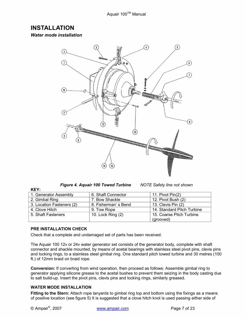
INSTALLATION Water mode installation
Figure 4. Aquair 100 Towed Turbine NOTE Safety line not shown KEY:
1. Generator Assembly 6. Shaft Connector 11. Pivot Pin(2)
2. Gimbal Ring 7. Bow Shackle 12. Pivot Bush (2)
3. Location Fasteners (2) 8. Fisherman’ s Bend 13. Clevis Pin (2)
4. Clove Hitch 9. Tow Rope 14. Standard Pitch Turbine
5. Shaft Fasteners 10. Lock Ring (2) 15. Coarse Pitch Turbine (grooved)
PRE INSTALLATION CHECK
Check that a complete and undamaged set of parts has been received. The Aquair 100 12v or 24v water generator set consists of the generator body, complete with shaft connector and shackle mounted, by means of acetal bearings with stainless steel pivot pins, clevis pins and locking rings, to a stainless steel gimbal ring. One standard pitch towed turbine and 30 metres (100 ft.) of 12mm braid on braid rope. Conversion: If converting from wind operation, then proceed as follows: Assemble gimbal ring to generator applying silicone grease to the acetal bushes to prevent them seizing in the body casting due to salt build-up. Insert the pivot pins, clevis pins and locking rings, similarly greased.
WATER MODE INSTALLATION
Fitting to the Stern: Attach rope lanyards to gimbal ring top and bottom using the fixings as a means of positive location (see figure 5) It is suggested that a clove hitch knot is used passing either side of
Aquair 100TM Manual
© Ampair®, 2007 www.ampair.com Page 8 of 23
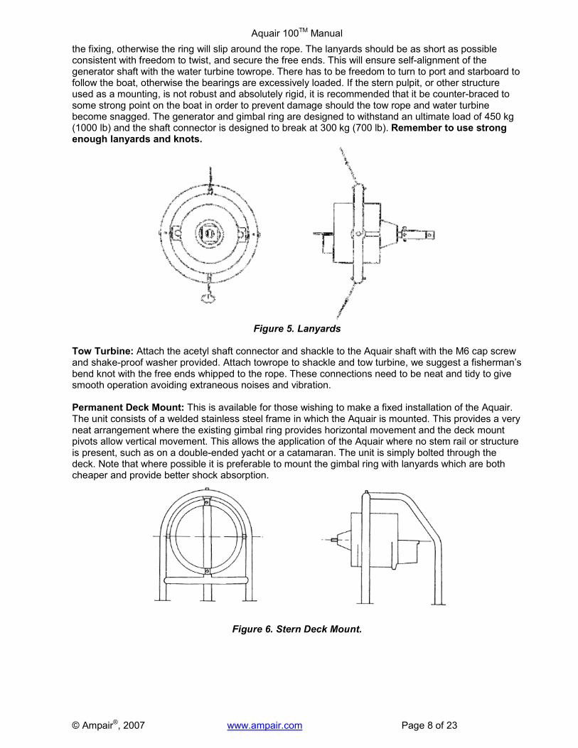
the fixing, otherwise the ring will slip around the rope. The lanyards should be as short as possible consistent with freedom to twist, and secure the free ends. This will ensure self-alignment of the generator shaft with the water turbine towrope. There has to be freedom to turn to port and starboard to follow the boat, otherwise the bearings are excessively loaded. If the stern pulpit, or other structure used as a mounting, is not robust and absolutely rigid, it is recommended that it be counter-braced to some strong point on the boat in order to prevent damage should the tow rope and water turbine become snagged. The generator and gimbal ring are designed to withstand an ultimate load of 450 kg (1000 lb) and the shaft connector is designed to break at 300 kg (700 lb). Remember to use strong enough lanyards and knots.
Figure 5. Lanyards
Tow Turbine: Attach the acetyl shaft connector and shackle to the Aquair shaft with the M6 cap screw and shake-proof washer provided. Attach towrope to shackle and tow turbine, we suggest a fisherman’s bend knot with the free ends whipped to the rope. These connections need to be neat and tidy to give smooth operation avoiding extraneous noises and vibration. Permanent Deck Mount: This is available for those wishing to make a fixed installation of the Aquair. The unit consists of a welded stainless steel frame in which the Aquair is mounted. This provides a very neat arrangement where the existing gimbal ring provides horizontal movement and the deck mount pivots allow vertical movement. This allows the application of the Aquair where no stem rail or structure is present, such as on a double-ended yacht or a catamaran. The unit is simply bolted through the deck. Note that where possible it is preferable to mount the gimbal ring with lanyards which are both cheaper and provide better shock absorption.
Figure 6. Stern Deck Mount.

Aquair 100TM Manual
© Ampair®, 2007 www.ampair.com Page 9 of 23
Wind Mode Installation - Hoist In Rigging (HIR)
Figure 7. Aquair Wind kit Hoist in Rigging. KEY:
1. Generator Assembly 6. Hub Plate (2) 11. Shaft Fasteners
2. Swivel Tube 7. Blade Fasteners (12) 12. Tail Vane
3. Swivel Tube Fasteners 8. Hub Fasteners (3) 13. Tail Vane Fasteners
4. Blade (6) 9. Hub Centre
5. Bung (3) 10. Guide Hole
PRE INSTALLATION CHECK
Check that a complete and undamaged set of parts has been received. The Aquair HIR set contains six wind turbine blades packed as three colour-coded & balanced pairs; one hub assembly complete with plastic bungs; two swivel poles; one tail vane; two hardware kits:
Kit 1: Wind blade fixings Kit 2: HIR fixings
12 M8 x 40mm hex bolts 2 M8 x 50mm hex bolts 1 5mm hexagon wrench (Allen key)
12 M8 nuts 2 M8 nuts 3 M6 x 16mm screws
12 M8 shake-proof washers 2 M8 shake-proof washers 3 M6 shake-proof washers
2 M6 x 30mm cap screws 3 M6 plain washers
2 M6 shake-proof washers 3 M6 nuts

Aquair 100TM Manual
© Ampair®, 2007 www.ampair.com Page 10 of 23
CONVERSION FROM TOW MODE TO WIND (for HIR kit):
Conversion: Find a suitable location for suspending the Aquair 100. The fore triangle is a safe area away from the cockpit. Remove the locking rings from the clevis pins and remove clevis pins, and pivot pins from the acetal bushes to release the generator. If stiff to remove, the bushes may be gently prised out by introducing a small lever through the holes in the sides of the pivot housings and engaging the groove in the bush. If completely corroded in, then fill centre hole with grease and use pivot pin as a piston to knock into hole and force bush out. Otherwise, the bush will have to be drilled out and replaced. Remove the acetal shaft connector. Swivel Poles: Attach the swivel poles to the generator “ears” using the M8x50mm bolts, shake-proof washers and nuts provided. Do not fit the turbine and tail vane. Suspension: Partially hoist the Aquair 100 to enable assembly of the tail vane and wind turbine. To minimise sway, connect the lower swivel to the deck by three guys at approximately 120 degrees to each other, viewed from above. Do not apply excessive tension since this will result in rapid wear of the PTFE swivel bearings. Cable: Secure the output wire to the lower swivel pole, allowing as much slack as possible without causing the cable to snag in the turbine. Wind vane: Using the three M6x16mm screws, washers and nuts provided, fit the vane (tail fin) to the rear of the Aquair body. Wind turbine assembly: First, check that the hub plates are correctly fitted to the hub-centre. (Some plates had a small hole near one of the 12 blade fixing holes and these should line up.) The blades are supplied as colour coded pairs (see the colour code on the blade base). These pairs should be assembled finger tight to the hub, in opposite positions, using the M8x40mm bolts shake-proof washers and nuts provided. The bolts are a deliberately tight fit but may be screwed in using a socket spanner. Note. The concave (hollow) side of the blade faces the wind. Tighten the blade bolts working on opposite pairs in sequence. It is a good idea to re-tighten fixings after a few hours use since some compression of the materials may have taken place. It is usual to
Figure 8: Aquair Hoist In Rigging Mounting

Aquair 100TM Manual
© Ampair®, 2007 www.ampair.com Page 11 of 23
leave the blade ‘disc’ assembled and store it as a disc after assembling it for the first time. Fitting the wind turbine: Remove the plastic bungs from the hub plate to gain access to the hub-centre to shaft fixing holes. Carefully align the wind turbine hub and gently slide on to the shaft. Using the M6x30mm cap screws shake-proof washers and hexagon wrench provided, fit the turbine to the shaft. Tighten fully. CAUTION: Leave a loop where the cable passes the swivel. This will allow the unit to rotate in the wind. Do not make the loop so big as to risk fouling the blades. DANGER: The wind turbine blades are easily capable of causing grave personal injury, even in light wind, and should be treated with the same respect as an aircraft propeller.
• It is essential that the wind turbine be hoisted well above head height.
• Do not let go of the blades until all personnel are clear. Rotate the Aquair to face the wind and step back before letting go.
Wind mode installation – Pole Mount
Figure 9. Aquair Wind Kit - Pole Mount
KEY:
1. Generator Assembly 7. Hub Centre 13. Mounting Pole
2. Blade (6) 8. Guide Hole 14. Pole Collar
3. Bung(3) 9. Turbine Fasteners (2) 15. Collar Fasteners (2)
4. Hub Plate (2) 10. Pivot Shaft 16. Tail Vane
5. Blade Fasteners (12) 11. Pivot Fasteners (1) 17. Tail Vane Fasteners (3)
6. Hub Fasteners (3) 12. Pivot Bush
PRE INSTALLATION CHECK
Check that a complete and undamaged set of parts has been received. The Aquair pole mount set contains: six wind turbine blades packed as three colour-coded & balanced pairs; Hub assembly and 3 plastic bungs; 800mm pole. tail vane; one pole mount adaptor set comprising an aluminium alloy pivot, acetal bush and aluminium alloy collar.

Aquair 100TM Manual
© Ampair®, 2007 www.ampair.com Page 12 of 23
Figure 10: Pole Mount Adaptor
The hardware kits contain:
Kit 1: Wind blade fixings Kit 2: PM fixings
12 M8 x 40mm hex bolts 1 M8 x 50mm hex bolt 3 M6 x 16mm screws
12 M8 nuts 1 M8 nut 3 M6 shake-proof washers
12 M8 shake-proof washers 1 M8 shake-proof washer 3 M6 plain washers
2 M6 x 30mm cap screws 3 M6 nuts
2 M6 shake-proof washers 2 M6 x 20mm screws
1 5mm hexagon wrench (Allen key)
2 M6 shake-proof washers
Note it is also possible to purchase the Pole Mount (i.e. 800mm pole + adaptor) or just the Pole Mount Adaptor for those who already have the HIR kit and are creating an alternative mounting position. Installation differs from the hoist method as follows:
1. Find a suitable position in which to mount the pole which many clients will incorporate in some form of stern gantry.
2. Adaptor set: Insert the acetal bush in the top of the pole, with the holes in the bush lined up with those in the pole. Pass the anodised collar over the pole and hold the collar so the threaded holes line up with those in the pole, whilst inserting the two M6x20mm screws with shake-proof washers just enough to enter the thickness of the bush. Do not fully screw in.
3. Pivot: Insert the pivot in one “ear” of the Aquair 100 body so the cable exit gland is downwards and, using the M8x50mm bolt, shake-proof washer and nut, tighten firmly.
4. Place the Aquair 100 on the pole, gently guiding the pivot down into the bush on the top of the pole. Fully tighten the two M6x20mm screws in the anodised collar. The threads now protrude into the groove in the pivot effectively trapping it in place.
5. Secure the cable in such a way that the Aquair can turn at least 360 degrees in each direction.
6. Finally, assemble the tail vane and then the wind turbine as for the HIR kit above. CAUTION: Leave a loop where the cable passes the adaptor. This will allow the unit to rotate in the wind. Do not make the loop so big as to risk fouling the blades. DANGER: The wind turbine blades are easily capable of causing grave personal injury, even in light wind, and should be treated with the same respect as an aircraft propeller.
• It is essential that the wind turbine be hoisted well above head height.
• Do not let go of the blades until all personnel are clear. Rotate the Aquair to face the wind and step back before letting go.

Aquair 100TM Manual
© Ampair®, 2007 www.ampair.com Page 13 of 23
Wind mode installation – Stern Mount Kit
The Aquair Pole Mount Generator can be mounted on the stern mount kit of the Ampair 100 Wind Generator. The Ampair 100 Stern Mount Kit includes an upright pole in three sections complete with joiner pieces, a backstay bracing strut, and two wire stays. If wishing to use a Stern Mount Kit with an Aquair 100 please advise when ordering as it is a special item. See Ampair 100 manual for Stern Mount Kit installation instructions.

Aquair 100TM Manual
© Ampair®, 2007 www.ampair.com Page 14 of 23
ELECTRICAL INSTALLATION Cables: The Aquair 100 is fitted with 5m of 1.5sq mm cable. Having sited the Aquair 100 on the boat, measure the cable run distance to the batteries. If this distance is less than 10 metres (20 metres 24v systems), use 1.5sq mm (16 AWG) cable. If less than 20 metres (40 metres 24v systems), use 2.5sq mm (14 AWG) cable. Use a similar type of cable to that on the Aquair. Always use tinned stranded conductors. Connectors: To carry power from the Aquair to the wiring on the boat we recommend that a quality watertight connector be fitted. In the case of a wind and water combination, a watertight socket can be fitted at each site. Alternatively, an extension cable with in-line connectors can be used for the wind mode. The plugs and especially the sockets should have watertight caps when not in use. Installation: Wiring between the deck socket (or junction box, deck gland etc.) and the battery area should be clipped at regular intervals to the structure for safety and a neat job Protection: The simplest possible arrangement feeds the power from the Aquair directly to the battery, through an in-line fuse rated at 10 Amps (5 Amps 24v system) in the positive line next to the battery.
Figure 12. Basic Wiring Wiring options: In fig. 12, two optional components have been added to show where they might be wired in the circuit.
o The switch, which may be used as a simple means of charge control, should be rated at 15 Amps DC to ensure long life.
o The ammeter is wired in series (assuming it to be of the internal shunt variety) in one line. This allows the machine output to be seen at all times. As shown, the positive (+) connection of the ammeter is made to the generator, whilst the negative (-) is made to the battery. Never connect an ammeter across the supply.
CAUTION: IT IS MOST IMPORTANT TO FIT A FUSE. The fuse should be next to the battery
terminal since, in the event of a fault or damage to the cable, the battery will supply a large fault-current.
CAUTION: When wiring the system be aware that if the Aquair is connected to the battery with
REVERSE POLARITY the output rectifiers can be destroyed. Check and double-check polarity before final connection. CABLE COLOURS: Core 1 (formerly BROWN) = + Positive
Core 2 (formerly BLUE) = - Negative. CAUTION: The Aquair generator output MUST GO STRAIGHT TO THE BATTERIES. If the Aquair
is connected on the DOWNSTREAM (load-side) of the battery isolator switch, it leaves scope for damage to electrical equipment on the boat. Under these conditions it is possible to run the Aquair whilst the battery is isolated. This can subject the system to excess voltage.
Core 1 = + (formerly BROWN)
Core 2 = + (formerly
BLUE)

Aquair 100TM Manual
© Ampair®, 2007 www.ampair.com Page 15 of 23
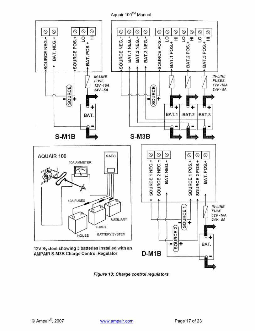
CHARGE CONTROL REGULATION In the water mode it is not recommended to use a regulator with the Aquair towed turbine as it can interfere with normal operation and cause the turbine to alternately surge and slow as the regulator disconnects and connects the generator to the battery. This can cause the rope to kink and become tangled. Ordinarily on cruising yachts the running loads approximately balance the Aquair charge. Should this not be the case, then a simple switch or removable connector can be used to allow the turbine to spin freely when not required. In the wind mode an Aquair used as a semi-permanent wind charger may well need regulation, in which case the appropriate model should be wired for connection in the wind mode only. Ampair manufactures three Charge Control Regulators for protecting lead acid batteries from overcharge. They are not “shunt” type regulators, which dissipate excess charge as heat, but an electronic power switch, which disconnects the generator from the battery at the regulation voltage. Regulators S1B & S3B have a single 100-watt input (Ampair, Aquair or UW). Regulator type S1B has one output battery connection. Regulator S3B has three output connections to serve up to three battery banks with a common negative. The third regulator D1B has two 100 watt inputs (any two from Ampair, Aquair, UW or solar panels), supplying a single battery bank at a fixed regulation voltage. All regulators have 2 level sensing. The lower voltage (Lo) connection regulates at 0.4 Volts below the high (Hi) connection for 12V systems (0.8V for 24V systems). “Hi’ connection is appropriate for liquid electrolyte batteries and/or live aboard situations. ‘Lo” connection for gel batteries and/or infrequent use. The battery voltage is sensed at the regulator output connection, therefore install the regulator as near the battery as practicable and keep the connecting cables short. Regulator type S1B has one output battery connection. Regulator S3B has three output connections to serve up to three battery banks with a common negative. The third regulator D1B has two 100 watt inputs (any two from Ampair, Aquair, UW or solar panels), supplying a single battery bank at a fixed regulation voltage. All regulators feature the same multi-stage regulation programme which has regulation voltages of Lo = 13.6V. Hi = 14.0V for l2V systems (27.2V & 28.0V for 24V systems). Charging is continuous until the Lo or Hi voltage is reached, depending on the battery output used. The generator is now disconnected from the battery. Off-charge, the battery voltage will fall. At a voltage of 0.5V below the regulation voltage a 30-second time delay is activated. This delay prevents the regulator from oscillation (hunting) when charging batteries under load. After 30 seconds has elapsed, the generator-to-battery connection is remade and charging continues to the regulation cut-out voltage. A cycle counter counts the charge/disconnect cycles and at the tenth cycle increases the regulation voltage for one cycle only by 0.4 volt to Lo 14.OV or Hi 14.4V for 12V systems (0.8V for 24V systems Lo = 28.OV, Hi = 28.8V). This provides an equalisation charge for the battery. Subsequent cycles return to the lower settings until a further 9 cycles are completed. Ammeter: We recommend fitting an ammeter to monitor charging. Use 10A for 12v, 5A for 24v. Fit an ammeter with a linear scale (moving coil type) or low outputs will be indiscernible. Fuses: Battery protection fuses should be fitted. Use l0A in 12v system, 5Amp for 24v. Wiring: Use suitably insulated cable of 1.5 sq. mm (16 A.W.G.) between regulator and battery in single source systems; 2.5 sq. mm (14 A.W.G.) for dual source. For input wiring to the regulator see appropriate generator wiring section. The use of screened cables is recommended if the cables run close to equipment radiating strong electrical fields e.g. radio transmitters or aerials.

Aquair 100TM Manual
© Ampair®, 2007 www.ampair.com Page 16 of 23
Installation of charge control regulator
Make sure the generator is not operating whilst connecting to the regulator. Connecting with live wires can damage the electronic regulation circuit. At initial start-up, allow a time of 1-2 minutes for circuit timing functions to become active. Protecting the system: Fuse warning - never omit fuses, simple in-line fuse carriers may be used, they protect your system from excessive battery currents in the event of a serious electrical fault. If they keep blowing, find out why. Fuses = l0A for 12V systems; 5A for 24V systems. The regulators are internally protected by SAE fuses, which are not substitutes for battery protection fuses. The fuses must be next to the battery terminals since, in the event of a fault, the batteries would source the fault current. Check and double-check polarities before making connections, insert the fuses in the fuse carriers last of all. Corrosion: This is the enemy of all electrical connections, especially in marine environments. Site regulators in a weather proof location, as dry as possible, and splash proof. Inspect all terminations and connections for signs of corrosion. Rectify by cleaning, remaking etc. Use tinned copper wire for extension leads to prevent corrosion spreading inside cable insulation. Operating problems: A digital multi-meter is useful for checking operational faults, if no permanent monitoring instruments are used. Battery voltage levels and those of the charging source can be read directly. Charging current readings will require the multi-meter to be installed in line. In this way currents into and out of the regulator can be observed. Do not remove battery connections since regulator operation depends on a very small supply current. If the regulator is suspect then it can be temporarily bypassed by connecting the source positive direct to a battery positive. The negative connections are common and do not need disturbing unless regulator replacement is necessary. Use the multi-meter continuity range to confirm all cable runs are low resistance. Operation: When installed, the generator and regulator will run and maintain the batteries automatically. The unit may be run in conjunction with any other charge-source with no known interactive problems. Regular battery inspection and topping up must still be carried out to obtain maximum battery life. Faulty regulator: Each regulator is individually tested and a chart recording kept of its operation. Each regulator has a unique serial number and a test date. Please provide these with any queries. If the regulator is suspect, then it can be temporarily bypassed i.e. connect the rectifiers directly to the battery terminals observing correct polarity. If this reinstates correct charging, then the regulator must be serviced or replaced. Regulators draw a small current (typically 1mA at 12V) from the battery to activate the sense and control circuits. Without this connection the regulator will be inoperative.
SERVICING.
If the regulator is suspect, then it can be temporarily by passed i.e. connect the generator directly to the battery terminals observing correct polarity. If this reinstates correct charging, then the regulator must be serviced or replaced. Regulators draw a small current (typically 1mA at 12v) from the battery to activate the sense and control circuits. Without this connection the regulator will be inoperative.
Aquair 100TM Manual
© Ampair®, 2007 www.ampair.com Page 17 of 23
Figure 13: Charge control regulators

Aquair 100TM Manual
© Ampair®, 2007 www.ampair.com Page 18 of 23
AQUAIR OPERATION & PERFORMANCE Operation – Water Mode:
It is assumed that the Aquair has been installed in accordance with the INSTALLATION section and that the water turbine and towrope are attached.
Streaming: Lay the towrope out on the deck in such a way that it can be played out without risk of snagging or knotting when the turbine is put in the water. This should be done when the boat is under way. Slight tension should be applied as it runs out to prevent the turbine grounding in shallow water. The towrope should not pass close to steering gear etc., which could cause chafing or worse.
CAUTION: The faster the speed of the boat the greater the forces on the mounting system (and the reduced time to respond to any mishaps). Therefore it is advisable to reduce speed when streaming the turbine, at least until the crew have become proficient.
WARNING: Once streamed the tow line and swivel are a piece of rotating equipment and should be treated with the appropriate level of care. Do not allow the tow rope to become entangled in hair, loose clothing, or rigging.
Adjustment: The standard pitch water turbine is likely to surface at speeds in excess of 7 knots, depending on sea state and the height above the water at which the Aquair is mounted. This can lead to snatching on the rope as the turbine jumps as it breaks surface and the possibility of the rope knotting or the turbine turning turtle and picking up its own rope. Matters can be improved (at the expense of performance at lower speeds due to increased droop) using one or more of the following methods:
1) Increase diameter of rope to 14mm and/or increase length of line to 40-50m. 2) Add weight to the turbine, e.g. stainless steel or brass tubing on the shaft. Some customers
have used sacrificial zinc anodes, of the type for clamping around a shaft, either on the turbine or the rope.
3) Place a short length of tubing over the end of the line to turbine shaft connection. This will stiffen the joint and keep the turbine inline.
Smaller yachts with lower cruising speeds (e.g. 35 foot length) may be able to shorten the rope by 10m to reduce drag without compromising performance. A coarse pitch turbine is recommended for boats that consistently exceed 8 knots. It will surface at 12 knots. There will, however, be a significant loss of performance at speeds below 8 knots (see graph of water driven performance). A coarse pitch water turbine has been used successfully at speeds up to 20 knots by increasing the rope diameter to 14mm and shortening its length to 15 metres so as to stay in the same wave as the boat. Coarse pitch turbines have a circumferential groove around the propeller for identification.
Recovery: Since the rope is spinning, to avoid hand injury, the boat should be slowed to 1-2 knots when hauling in. A useful device, to help when hauling-in whilst under way, may be made from a large plastic funnel, with most of the spout cut off, slit down the side and fitted with Velcro straps. This is slid down the towrope where it will stop the turbine spinning, allowing easier retrieval. Alternatively use a split fender with its centre hollowed out. Another technique is to take a sausage fender with a karabiner (sprung shackle) and clip it over the rope at either end. It will run down to the turbine and stop it spinning and simultaneously keep it near the surface.
CAUTION: To avoid personal injury, wear sturdy gloves as a precaution. Reduce speed when hauling-in since the water turbine has considerable torque.
Operation – Wind Mode:
Starting up: It is assumed that the Aquair has been assembled and installed in accordance with the section on INSTALLATION. The unit is not designed for permanently unattended operation, it is important to occasionally check to see that the output cable has not trapped round the swivel (or pole) due to wind veer/boat movement. Stopping: The wind turbine has been designed to survive storms, however, it is a good plan to stop the machine if a gale is expected. To do this, proceed with caution, approach the Aquair from downwind and grasp the tail vane with a boathook or similar. Carefully turn the machine off wind and, when the blades stop, throw a rope over them and tie down. If a hurricane is expected take the unit down.
CAUTION: To avoid personal injury, wear sturdy gloves as a precaution. The wind turbine blades are capable of causing GRAVE INJURY and should be treated with the same respect as an aircraft propeller.

Aquair 100TM Manual
© Ampair®, 2007 www.ampair.com Page 19 of 23
These graphs show the Aquair 100 performance and drag at a range of speeds.
Figure 16. Wind Driven Performance
The drag due to the wind turbine is about 22kg (50lbs) at 50 knots wind speed.
Figure 14. Water Driven Performance
Figure 15. Water Driven Drag

Aquair 100TM Manual
© Ampair®, 2007 www.ampair.com Page 20 of 23
MAINTENANCE AND SPARES
Figure 17. Sectioned Drawing
KEY:
1. After-body 2. Bearing (2): 15x3 x11mm sealed
3. Stator (2) Six pole 4. 0’ ring: international size 358
5. Fore-body 6. Rotor (2) Permanent Magnet
7. Internal circlip: 35x1.5mm 8. Shaft seal 15x35x7mm rubber coated, plain lip
9. Shaft: with two M6 tapped holes 10. Body fasteners (2): M8x25mm hex set screw with shake-proof, fibre & plain washer
11. Cable gland with strain relief 12. Output cable: 5m of 1.5sq mm, twin-cored, tinned copper wire, outer sheath of low temperature grade PVC
13. Rectifiers (2): rated at 25 Amp 600v 14. Rectifier fasteners (2): M5x16mm pan head screw & shake-proof washer
15. Rectifier cover 16. Cover fasteners (4): # 8x3/8” self tapping screw & M4 fibre washer
Inspection
The shaft seal protecting the front bearing should be renewed regularly, particularly after long ocean voyages. The bearings should be replaced when they become noisy. In water mode, regularly inspect the following: suspension lanyards, shaft connector & shackle, tow rope attachments and gimbal pivot components. Inspect the body and tow turbine occasionally, cleaning off any corrosion and re-painting any damaged areas. The shaft connector has a second set of holes, which can be used once the original holes show signs of wear or elongation. If the tow turbine blade tip becomes bent as shown in Fig. 18, this will cause a change in pitch, increased drag and premature surfacing. View the trailing edge of the blade, edge on, as shown. The

Aquair 100TM Manual
© Ampair®, 2007 www.ampair.com Page 21 of 23
edge should appear as a straight line with the pitch angle at 15 degrees close to the tip (standard pitch turbine). If this is bent, tap the tip back into shape using a support block as shown.
Figure 18. Water Turbine Maintenance
In wind mode: regularly inspect the following: hub to shaft screws, blade bolts & nuts, hub centre screws, wind turbine blades, tail vane screws and swivel pole (or pole mount) bolts. Inspect the machine after stormy weather for signs of accidental damage. Any minor nicks in the edge of a blade may be dressed out, but the blade must be replaced if there is any sign of damage or cracking near the root. Since the blades are supplied as matched, balanced pairs, any damaged blade must be replaced along with its opposite number. The unit may be run with two blades missing (whilst the replacements are obtained) at reduced performance since difficulty in starting will be encountered. WARNING: NEVER ALLOW THE MACHINE TO RUN OUT OF BALANCE The blade material has exceptional fatigue resistance, which is of the utmost importance in hostile locations, such as those with tropical sunshine and on mountains. The material is subject to slow degradation due to ultra violet light, which increases towards the equator and with altitude. The deterioration is slow and when it become apparent as a whitening of the blade surface, particularly along leading and tailing edges, the blades may be carefully painted with two-pack polyurethane after a light sanding. CAUTION: DO NOT MIX UP THE BALANCED PAIRS!
Major disassembly
Should the generator have to be taken apart for any reason, some force may be needed to break the “Loctite” bearing joints and ‘O’ ring sealing. If difficulty is experienced, a puller may have to be improvised. Referring to the drawing, remove the fore-body carefully as it cannot be totally withdrawn due to the front stator wiring connection. This job should be done on a suitable workbench. The rear bearing needs a bearing puller to remove it, if no puller is available, a dummy shaft may be fixed in the bearing centre using epoxy adhesive and, when cured, the bearing worked loose. The front bearing may be drifted out following removal of the seal and circlip. Prior to re-assembly, the bearing housings, the bearings inner and outer surfaces and the shaft surfaces should all be thoroughly cleaned and degreased. When reassembling use adhesives as follows:
Stator to body – use Loctite 648, Bearings to body – use Loctite 641, Shaft to bearings – use Loctite 641.
When replacing the fore-body, make sure that the ‘O’ ring is in place and well smeared with silicone grease. Assemble the body checking that the wiring to the front stator cannot touch the rotor. Ensure

Aquair 100TM Manual
© Ampair®, 2007 www.ampair.com Page 22 of 23
that the timing marks on the body junction line coincide. If the “cogging” or breakout torque has been correctly minimised, 12 minor and equal “lumps” of resistance per revolution will be felt when turning the shaft by hand. This resistance should not exceed 2kg-cm (30oz-in). When doing this make sure that the output leads are not shorted together. Reduced output: Possible faults to consider if reduced output is suspected: Poor or corroded wiring connections. Inspect all the screw terminals in the Aquair circuit for signs of fatigue or corrosion (the commonest cause of reduced output is corroded wiring between generator & battery). A simple method of checking the machines output is to disconnect it from the battery and short together its output leads whilst turning the shaft by hand. A marked increase in resistance to turning should be felt as the shorting takes place. Faulty stator: Check AC input to rectifiers or check for coil continuity and isolation from the case. The resistance should be less than 2 ohms (approx. 6 ohms 24V units). Stator replacement involves baking in an oven to break the adhesive bond and is best undertaken at the factory. Rectifiers: The rectifiers are located in the small box on the back of the Aquair body. To inspect them, remove the four screws and the plate. This has been sealed with polyurethane sealant. The sealant must be renewed on re-assembly after the mating faces have been cleaned. Damp, salt laden air will be sucked inside the generator if the seal is not effective.
Figure 19. Aquair 100 Internal Wiring Diagram
RECTIFIER DIODE TEST:
This test will show if the rectifier diodes are either open or short circuit. If your multi-meter has a diode check feature, select this (if not select the highest resistance range). Connect the meter leads to the DC output and note the reading. Now reverse the connections.
MULTIMETER SETTING METER LEAD POSITION
DIODE TEST OHMS x 100
CONCLUSION
No reading or Many Megohms* OK RED meter lead to positive
Reading or Low resistance Failed
1.2V (two diode drops)
or Markedly less* OK BLACK meter lead to positive
No reading or High resistance Failed
*This test is not as conclusive as the diode test method, however, provided the first reading is a very high resistance and the second reading far lower, then the test is valid. Actual values will depend on the voltage supplied by the particular meter for its resistance ranges and some meters cannot check 2 diodes in series.
To replace faulty rectifiers unsolder the common links between the rectifier DC outputs and check outputs separately. If a new rectifier has to be fitted, scrape the enamel off the stator wires before soldering and re-sleeve.

Aquair 100TM Manual
© Ampair®, 2007 www.ampair.com Page 23 of 23
RECOMMENDED SPARES
For ocean passages a spare water turbine and shaft connector are recommended. When speeds of over 8 knots are frequently encountered a coarse pitch turbine should be chosen as the spare to allow a choice. To cater for accidental damage in the wind driven mode, it is suggested that a spare pair of blades be carried Other spares worth considering are 2 bearings as an insurance policy, 2 rectifiers (unlikely to be required unless polarity is accidentally reversed), shaft seal (regular replacement required, dependant on use), pivot pin & bush set, and a shaft connector to cater for wear or over strain.
DIMENSIONS.
Aquair Body.
Shaft diameter 15mm
Gimbal ring diameter 280mm (11”)
Body diameter (over pivot ears)
220mm (8.66”)
Body diameter 175mm (6.89”)
Body length (including shaft connector)
340mm (13.4’)
Body length 3 10mm (12.2”)
Generator and gimbal weight 9kg (211b.)
Water Turbine and Rope
Turbine length 770mm (30”)
Turbine diameter 280mm (11”)
Turbine weight 3kg (7 lb.)
Tow rope diameter 12mm (.5”)
Tow rope length 30m (100’)
Rope weight 3kg (71b)
Wind Mode Hoist in Rigging
Swivel pole height over all 1140mm (45”)
Swivel pole outside diameter 29mm (1.13”)
Turning radius 480mm (19”)
Wind turbine blade diameter 915mm (36”)
Suspended weight 13kg (28")
Wind Mode Pole Mount
Mounting pole length 800mm (31.5”)
Mounting pole outside diameter
44mm (1.75”)
Mounting pole inside diameter 38mm (1.5”)
Turning radius 480 mm (19”)
Mounted weight including pole 13kg (28lb)
WARRANTY Please see Ampair terms and conditions, available on request. Please keep your invoice as proof of purchase.
SERVICING & REPAIRS Units should be returned to:
Ampair Park Farm, West End Lane, Warfield Berkshire RG42 5RH United Kingdom Tel +44 (0) 1344 303 313 Fax +44 (0) 1344 303 312 Email: [email protected] Web: www.ampair.com
Ampair reserves the right to change specifications, without prior notice, in the interest of product development.