AquaFast - helden-web.com
28
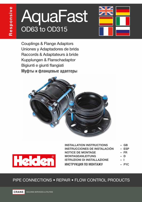
PIPE CONNECTIONS • REPAIR • FLOW CONTROL PRODUCTS INSTALLATION INSTRUCTIONS – GB INSTRUCCIONES DE INSTALACIÓN – ESP NOTICE DE MONTAGE – FR MONTAGEANLEITUNG – D ISTRUZIONI DI INSTALLAZIONE – I ИНСТРУКЦИЯ ПО МОНТАЖУ – PYC AquaFast Couplings & Flange Adaptors Uniones y Adaptadores de brida Raccords & Adaptateurs à bride Kupplungen & Flanschadaptor Bigiunti e giunti flangiati Муфты и фланцевые адаптеры OD63 to OD315 Responsive
Transcript of AquaFast - helden-web.com
PIPE CONNECTIONS • REPAIR • FLOW CONTROL PRODUCTS
INSTALLATION INSTRUCTIONS – GBINSTRUCCIONES DE INSTALACIÓN – ESPNOTICE DE MONTAGE – FRMONTAGEANLEITUNG – DISTRUZIONI DI INSTALLAZIONE – I
ИНСТРУКЦИЯ ПО МОНТАЖУ – PYC
AquaFastCouplings & Flange AdaptorsUniones y Adaptadores de bridaRaccords & Adaptateurs à brideKupplungen & FlanschadaptorBigiunti e giunti flangiatiМуфты и фланцевые адаптеры
OD63 to OD315
Re
sp
on
siv
e
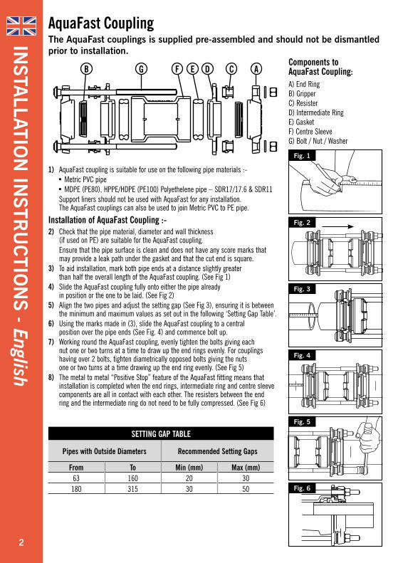
1) AquaFast coupling is suitable for use on the following pipe materials :-• Metric PVC pipe• MDPE (PE80), HPPE/HDPE (PE100) Polyethelene pipe – SDR17/17.6 & SDR11
Support liners should not be used with AquaFast for any installation. The AquaFast couplings can also be used to join Metric PVC to PE pipe.
Installation of AquaFast Coupling :-2) Check that the pipe material, diameter and wall thickness
(if used on PE) are suitable for the AquaFast coupling. Ensure that the pipe surface is clean and does not have any score marks that
may provide a leak path under the gasket and that the cut end is square.3) To aid installation, mark both pipe ends at a distance slightly greater
than half the overall length of the AquaFast coupling. (See Fig 1)4) Slide the AquaFast coupling fully onto either the pipe already
in position or the one to be laid. (See Fig 2)5) Align the two pipes and adjust the setting gap (See Fig 3), ensuring it is between
the minimum and maximum values as set out in the following ‘Setting Gap Table’.6) Using the marks made in (3), slide the AquaFast coupling to a central
position over the pipe ends (See Fig. 4) and commence bolt up.7) Working round the AquaFast coupling, evenly tighten the bolts giving each
nut one or two turns at a time to draw up the end rings evenly. For couplings having over 2 bolts, tighten diametrically opposed bolts giving the nuts one or two turns at a time drawing up the end ring evenly. (See Fig 5)
8) The metal to metal “Positive Stop” feature of the AquaFast fitting means that installation is completed when the end rings, intermediate ring and centre sleeve components are all in contact with each other. The resisters between the end ring and the intermediate ring do not need to be fully compressed. (See Fig 6)
AquaFast CouplingThe AquaFast couplings is supplied pre-assembled and should not be dismantled prior to installation.
Fig. 1
Fig. 3
Fig. 4
Fig. 6
Fig. 5
Fig. 2
Components to AquaFast Coupling:A) End Ring B) Gripper C) Resister D) Intermediate Ring E) Gasket F) Centre Sleeve G) Bolt / Nut / Washer
SETTING GAP TABLE
Pipes with Outside Diameters Recommended Setting Gaps
From To Min (mm) Max (mm)63 160 20 30
180 315 30 50
AB CDEFG
INSTA
LLATION
INSTR
UC
TION
S - English
2
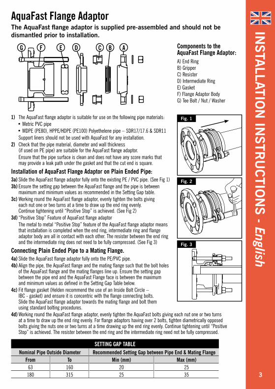
AquaFast Flange AdaptorThe AquaFast flange adaptor is supplied pre-assembled and should not be dismantled prior to installation.
Fig. 1
Fig. 2
Fig. 3
Components to the AquaFast Flange Adaptor:A) End Ring B) Gripper C) Resister D) Intermediate Ring E) Gasket F) Flange Adaptor Body G) Tee Bolt / Nut / Washer
SETTING GAP TABLENominal Pipe Outside Diameter Recommended Setting Gap between Pipe End & Mating Flange
From To Min (mm) Max (mm)63 160 20 25
180 315 25 35
ABCDEFG
INSTA
LLATION
INSTR
UC
TION
S - English
1) The AquaFast flange adaptor is suitable for use on the following pipe materials:• Metric PVC pipe• MDPE (PE80), HPPE/HDPE (PE100) Polyethelene pipe – SDR17/17.6 & SDR11
Support liners should not be used with AquaFast for any installation.2) Check that the pipe material, diameter and wall thickness
(if used on PE pipe) are suitable for the AquaFast flange adaptor. Ensure that the pipe surface is clean and does not have any score marks that
may provide a leak path under the gasket and that the cut end is square.
Installation of AquaFast Flange Adaptor on Plain Ended Pipe:3a) Slide the AquaFast flange adaptor fully onto the existing PE / PVC pipe. (See Fig 1)3b) Ensure the setting gap between the AquaFast flange and the pipe is between
maximum and minimum values as recommended in the Setting Gap table.3c) Working round the AquaFast flange adaptor, evenly tighten the bolts giving
each nut one or two turns at a time to draw up the end ring evenly. Continue tightening until “Positive Stop” is achieved. (See Fig 2)
3d) “Positive Stop” Feature of AquaFast flange adaptor The metal to metal “Positive Stop” feature of the AquaFast flange adaptor means
that installation is completed when the end ring, intermediate ring and flange adaptor body are all in contact with each other. The resister between the end ring and the intermediate ring does not need to be fully compressed. (See Fig 3)
Connecting Plain Ended Pipe to a Mating Flange.4a) Slide the AquaFast flange adaptor fully onto the PE/PVC pipe.4b) Align the pipe, the AquaFast flange and the mating flange such that the bolt holes
of the AquaFast flange and the mating flanges line up. Ensure the setting gap between the pipe end and the AquaFast Flange face is between the maximum and minimum values as defined in the Setting Gap Table below.
4c) Fit flange gasket (Helden recommend the use of an Inside Bolt Circle – IBC - gasket) and ensure it is concentric with the flange connecting bolts. Slide the AquaFast flange adaptor towards the mating flange and bolt them using standard bolting procedures.
4d) Working round the AquaFast flange adaptor, evenly tighten the AquaFast bolts giving each nut one or two turns at a time to draw up the end ring evenly. For flange adaptors having over 2 bolts, tighten diametrically opposed bolts giving the nuts one or two turns at a time drawing up the end ring evenly. Continue tightening until “Positive Stop” is achieved. The resister between the end ring and the intermediate ring need not be fully compressed.
3
INSTA
LLATION
INSTR
UC
TION
S - English
Storage Instructions Store the product in its original packing. In a clean and dry environment prior to installation.Ensure AquaFast is clean and free from all debris or contaminants before and during installation.
When used with Protective Layered / Colour Coated PipeWhen used on PE pipe with external protection layers, remove protection layer to beyond the insertion depth of the fitting, this is to ensure that sealing and gripping is made directly on to the PE surface and not the protective outer layer.
When used with PE Barrier Pipe for use in Contaminated GroundAquaFast has not been tested or designed to work with PE barrier pipe, therefore we do not recommend its use. Seek further advice from the PE barrier pipe manufacture for approved fittings.
When used with Oval and Coiled PipeIt should be noted that coiled pipe in its restrained form may exhibit a higher degree of ovality; This can also occur to straight pipes when stacked for prolonged periods. AquaFast is a dedicated product and does not allow a high degree of ovality in the pipe end. The pipe should be checked for ovality before use and if necessary should be re rounded by suitable equipment.For further advice on installation of this product contact Helden Marketing Department.
AquaFast Product NotesIn addition to the fitting instructions please also take note of the following when installing AquaFast Products.
4
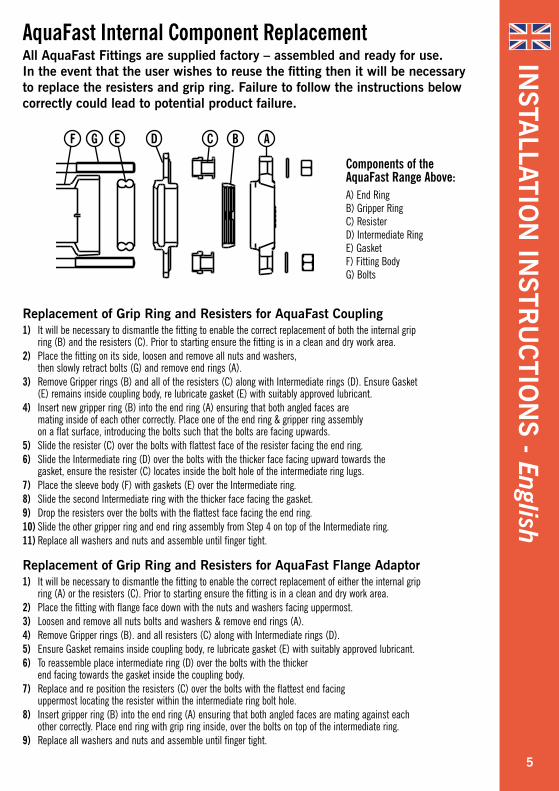
Replacement of Grip Ring and Resisters for AquaFast Coupling 1) It will be necessary to dismantle the fitting to enable the correct replacement of both the internal grip
ring (B) and the resisters (C). Prior to starting ensure the fitting is in a clean and dry work area.2) Place the fitting on its side, loosen and remove all nuts and washers,
then slowly retract bolts (G) and remove end rings (A). 3) Remove Gripper rings (B) and all of the resisters (C) along with Intermediate rings (D). Ensure Gasket
(E) remains inside coupling body, re lubricate gasket (E) with suitably approved lubricant. 4) Insert new gripper ring (B) into the end ring (A) ensuring that both angled faces are
mating inside of each other correctly. Place one of the end ring & gripper ring assembly on a flat surface, introducing the bolts such that the bolts are facing upwards.
5) Slide the resister (C) over the bolts with flattest face of the resister facing the end ring.6) Slide the Intermediate ring (D) over the bolts with the thicker face facing upward towards the
gasket, ensure the resister (C) locates inside the bolt hole of the intermediate ring lugs. 7) Place the sleeve body (F) with gaskets (E) over the Intermediate ring.8) Slide the second Intermediate ring with the thicker face facing the gasket.9) Drop the resisters over the bolts with the flattest face facing the end ring.10) Slide the other gripper ring and end ring assembly from Step 4 on top of the Intermediate ring.11) Replace all washers and nuts and assemble until finger tight.
Replacement of Grip Ring and Resisters for AquaFast Flange Adaptor 1) It will be necessary to dismantle the fitting to enable the correct replacement of either the internal grip
ring (A) or the resisters (C). Prior to starting ensure the fitting is in a clean and dry work area.2) Place the fitting with flange face down with the nuts and washers facing uppermost. 3) Loosen and remove all nuts bolts and washers & remove end rings (A). 4) Remove Gripper rings (B). and all resisters (C) along with Intermediate rings (D). 5) Ensure Gasket remains inside coupling body, re lubricate gasket (E) with suitably approved lubricant. 6) To reassemble place intermediate ring (D) over the bolts with the thicker
end facing towards the gasket inside the coupling body. 7) Replace and re position the resisters (C) over the bolts with the flattest end facing
uppermost locating the resister within the intermediate ring bolt hole.8) Insert gripper ring (B) into the end ring (A) ensuring that both angled faces are mating against each
other correctly. Place end ring with grip ring inside, over the bolts on top of the intermediate ring. 9) Replace all washers and nuts and assemble until finger tight.
Components of the AquaFast Range Above:A) End Ring B) Gripper Ring C) Resister D) Intermediate Ring E) Gasket F) Fitting Body G) Bolts
AquaFast Internal Component ReplacementAll AquaFast Fittings are supplied factory – assembled and ready for use. In the event that the user wishes to reuse the fitting then it will be necessary to replace the resisters and grip ring. Failure to follow the instructions below correctly could lead to potential product failure.
INSTA
LLATION
INSTR
UC
TION
S - English
ABCDEGF
5

1) La unión AquaFast es adecuada para su uso en tuberías de los siguientes materiales:• Tuberías de PVC• MDPE (PE80), HPPE/HDPE (PE100) Tuberías de Polietileno - SDR17/17.6 y SDR11
No se deben utilizar casquillos rigidizadores en ningún caso. Las uniones AquaFast también se pueden emplear para conectar tuberías de PVC con PE.
Instalación de la unión AquaFast.2) Compruebe que el material de la tubería, diámetro y espesor de pared
(si se usa en PE) son adecuados para la unión AquaFast. Asegúrese que la superficie de la tubería está limpia y sin marcas ni estrías que
pudieran ocasionar fugas bajo la goma y que el corte final del tubo es perpendicular.3) Para ayudarse en la instalación marque en los dos extremos de
los tubos a unir una distancia ligeramente mayor que la mitad de la longitud total de la unión AquaFast (Ver Fig. 1)
4) Deslice la unión AquaFast completamente sobre la tubería que ya está instalada o sobre la tubería a ser montada (Ver Fig. 2)
5) Alinee las dos tuberías y ajuste la separación de montaje (Ver Fig. 3), asegurándose que dicha separación está entre los valores mínimo y máximo dados en la siguiente “Tabla de Separación de Montaje”.
6) Utilizando las marcas hechas en el paso (3), deslice la unión AquaFast a la posición central sobre los extremos de los tubos (Ver Fig. 4) y comience a apretar los tornillos.
7) Apriete los tornillos trabajando en todo el contorno de la unión de manera uniforme dando a cada tuerca una o dos vueltas cada vez para que los anillos exteriores se acerquen uniformemente. Para uniones con más de 2 tornillos, apriétense de forma diametralmente opuesta, dando a las tuercas una o dos vueltas cada vez para acercar el anillo exterior de manera uniforme (Ver Fig.5)
8) El “Tope Positivo” metal-metal, característico de los accesorios AquaFast, implica que la instalación se ha completado cuando los anillos exteriores, anillos intermedios y anillo central quedan en perfecto contacto unos con otros. Los elementos resistentes entre el anillo exterior y el anillo intermedio no necesitan quedar totalmente comprimidos. (Ver Fig. 6)
Union AquaFastLas uniones AquaFast se suministran pre-montadas y no deben ser desmontadas antes de instalarse.
Fig. 1
Fig. 3
Fig. 4
Fig. 6
Fig. 5
Fig. 2
Partes de la unión AquaFast:A) Anillo Exterior B) Anillo de agarre C) Elemento resistente D) Anillo Intermedio E) Junta F) Anillo Central G) Tornillo/Tuerca/Arandela
TABLA DE SEPARACION DE MONTAJE
Tuberías con diámetros exteriores Separaciones de montaje recomendadasDesde Hasta Min (mm) Max (mm)
63 160 20 30180 315 30 50
AB CDEFG
INSTR
UC
CIO
NES D
E IN
STALA
CIÓ
N - Español
6
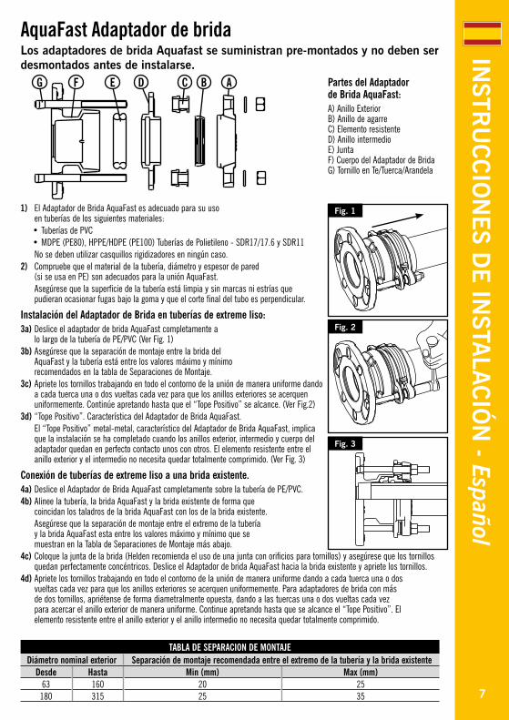
AquaFast Adaptador de bridaLos adaptadores de brida Aquafast se suministran pre-montados y no deben ser desmontados antes de instalarse.
Fig. 1
Fig. 2
Fig. 3
Partes del Adaptador de Brida AquaFast:A) Anillo Exterior B) Anillo de agarre C) Elemento resistente D) Anillo intermedio E) Junta F) Cuerpo del Adaptador de Brida G) Tornillo en Te/Tuerca/Arandela
TABLA DE SEPARACION DE MONTAJEDiámetro nominal exterior Separación de montaje recomendada entre el extremo de la tubería y la brida existente
Desde Hasta Min (mm) Max (mm)63 160 20 25180 315 25 35
ABCDEFG
INSTR
UC
CIO
NES D
E IN
STALA
CIÓ
N - Español
1) El Adaptador de Brida AquaFast es adecuado para su uso en tuberías de los siguientes materiales:• Tuberías de PVC• MDPE (PE80), HPPE/HDPE (PE100) Tuberías de Polietileno - SDR17/17.6 y SDR11
No se deben utilizar casquillos rigidizadores en ningún caso.2) Compruebe que el material de la tubería, diámetro y espesor de pared
(si se usa en PE) son adecuados para la unión AquaFast. Asegúrese que la superficie de la tubería está limpia y sin marcas ni estrías que
pudieran ocasionar fugas bajo la goma y que el corte final del tubo es perpendicular.
Instalación del Adaptador de Brida en tuberías de extreme liso:3a) Deslice el adaptador de brida AquaFast completamente a
lo largo de la tubería de PE/PVC (Ver Fig. 1)3b) Asegúrese que la separación de montaje entre la brida del
AquaFast y la tubería está entre los valores máximo y mínimo recomendados en la tabla de Separaciones de Montaje.
3c) Apriete los tornillos trabajando en todo el contorno de la unión de manera uniforme dando a cada tuerca una o dos vueltas cada vez para que los anillos exteriores se acerquen uniformemente. Continúe apretando hasta que el “Tope Positivo” se alcance. (Ver Fig.2)
3d) “Tope Positivo”. Característica del Adaptador de Brida AquaFast. El “Tope Positivo” metal-metal, característico del Adaptador de Brida AquaFast, implica
que la instalación se ha completado cuando los anillos exterior, intermedio y cuerpo del adaptador quedan en perfecto contacto unos con otros. El elemento resistente entre el anillo exterior y el intermedio no necesita quedar totalmente comprimido. (Ver Fig. 3)
Conexión de tuberías de extreme liso a una brida existente.4a) Deslice el Adaptador de Brida AquaFast completamente sobre la tubería de PE/PVC.4b) Alinee la tubería, la brida AquaFast y la brida existente de forma que
coincidan los taladros de la brida AquaFast con los de la brida existente. Asegúrese que la separación de montaje entre el extremo de la tubería
y la brida AquaFast esta entre los valores máximo y mínimo que se muestran en la Tabla de Separaciones de Montaje más abajo.
4c) Coloque la junta de la brida (Helden recomienda el uso de una junta con orificios para tornillos) y asegúrese que los tornillos quedan perfectamente concéntricos. Deslice el Adaptador de brida AquaFast hacia la brida existente y apriete los tornillos.
4d) Apriete los tornillos trabajando en todo el contorno de la unión de manera uniforme dando a cada tuerca una o dos vueltas cada vez para que los anillos exteriores se acerquen uniformemente. Para adaptadores de brida con más de dos tornillos, apriétense de forma diametralmente opuesta, dando a las tuercas una o dos vueltas cada vez para acercar el anillo exterior de manera uniforme. Continue apretando hasta que se alcance el “Tope Positivo”. El elemento resistente entre el anillo exterior y el anillo intermedio no necesita quedar totalmente comprimido.
7
INSTR
UC
CIO
NES D
E IN
STALA
CIÓ
N - Español
Instrucciones de almacenamientoAlmacene el producto en su embalaje original, en ambiente limpio y seco hasta el momento de su instalación.Asegurese que el AquaFast está limpio y sin polvo y suciedades antes y durante su instalación.
Cuando se use en tuberías con revestimiento:Cuando se use en tuberías de PE con protecciones externas retírese la capa protectora hasta más allá de la profundidad de inserción del accesorio para asegurar que tanto el sellado como el agarre se producen directamente sobre la superficie del PE y no sobre la capa protectora.
Cuando se use en tuberías de polietileno para protección en suelos contaminados:AquaFast no se ha diseñado para trabajar en este tipo de tuberías. Por lo tanto no se recomienda su uso.
Cuando se use en tuberías enrolladas ovalizadas:Nótese que una tubería enrollada puede presentar un mayor grado de ovalidad.Esto también puede ocurrir en tuberías en barra cuando han estado almacenadas por largos periodos de tiempo. AquaFast es un producto sin tolerancia y no admite un alto grado de ovalidad en el extremo de la tubería. Se debe controlar dicha ovalidad antes de su empleo y si es necesario redondearla con los medios adecuados.Contacte con el Departamento de Marketing de Helden para más información.
AquaFast. NotasAdemás de las instrucciones de instalación, téngase en cuenta lo siguiente cuando se instalan los productos AquaFast.
8

Reposición del Anillo de Agarre y de los elementos resistentes en la unión AquaFast1) Será necesario desmontar el accesorio para permitir la reposición del anillo de agarre (B) y de los elementos
resistentes (C). Antes de comenzar, asegúrese que el accesorio está en un área de trabajo limpia y seca.2) Afloje y quite todas las tuercas y arandelas. Después extraiga con cuidado
los tornillos (G) y retire los anillos exteriores (A)3) Retire los anillos de agarre (B) y todos los elementos resistentes (C) junto con los anillos intermedios (D).
Asegúrese que la junta (E) queda dentro del cuerpo de la unión y lubríquela con el lubricante adecuado.4) Inserte el nuevo anillo de agarre (B) en el interior del anillo exterior (A) asegurándose que las caras
achaflanadas encajan una con otra perfectamente. Coloque el anillo exterior y anillo de agarre montado sobre una superficie plana, introduciendo los tornillos de manera que miren hacia arriba.
5) Deslice el elemento resistente (C) sobre los tornillos con la cara plana del elemento resistente mirando hacia el anillo exterior.
6) Deslice el anillo intermedio (D) sobre los tornillos, con la parte más gruesa mirando hacia la junta, asegurándose que cada elemento resistente (C) se coloca dentro del taladro en la orejeta del anillo intermedio.
7) Coloque el cuerpo (F) con la juntas (E) sobre el anillo intermedio8) Deslice el segundo anillo intermedio con la cara más gruesa mirando hacia la junta.9) Coloque los elementos resistentes en cada tornillo con la cara plana mirando hacia el anillo exterior.10) Coloque el otro conjunto anillo de agarre-anillo exterior del paso 4 sobre el anillo intermedio.11) Coloque de nuevo todas las arandelas y tuercas y apriételas a mano.
Reposición del Anillo de Agarre y de los elementos resistentes en el Adaptador de Brida AquaFast1) Será necesario desmontar el accesorio para permitir la reposición del anillo de agarre (B) y de los elementos
resistentes (C). Antes de comenzar, asegúrese que el accesorio está en un área de trabajo limpia y seca.2) Coloque el accesorio con la brida hacia abajo y las tuercas y arandelas hacia arriba.3) Afloje y quite tuercas, arandelas y tornillos y retire el anillo exterior (A).4) Retire el anillo de agarre (B) y los elementos resistentes (C) junto con el anillo intermedio (D)5) Asegúrese que la junta (E) queda dentro del cuerpo y lubríquela con el lubricante adecuado.6) Para volver a montar coloque el anillo intermedio (D) sobre los tornillos con la
cara más gruesa mirando hacia la junta dentro del cuerpo.7) Reponga y coloque los elementos resistentes (C) en cada tornillo con la cara
plana mirando hacia arriba en el taladro del anillo intermedio.8) Inserte el anillo de agarre (B) dentro del anillo exterior (A) asegurándose que las caras
achaflanadas encajan una con otra perfectamente. Coloque el anillo exterior con el anillo de agarre en su interior sobre los tornillos, encima del anillo intermedio.
9) Coloque de nuevo todas las arandelas y tuercas y apriételas a mano.
Partes del accesorio AquaFast:A) Anillo Exterior B) Anillo de Agarre C) Elemento resistente D) Anillo Intermedio E) Junta F) Cuerpo del accesorio G) Tornillos
Reposición de los componentes internosTodos los accesorios AquaFast se suministran montados de fábrica y listos para su uso. En el caso de que el usuario desee reutilizar el accesorio tendrá que reemplazar los elementos resistentes y el anillo de agarre. Si no se siguen las instrucciones mostradas a continuación existe un alto riesgo de fallo.
INSTR
UC
CIO
NES D
E IN
STALA
CIÓ
N - Español
ABCDEGF
9
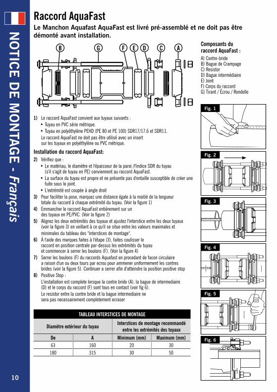
1) Le raccord AquaFast convient aux tuyaux suivants :• Tuyau en PVC série métrique.• Tuyau en polyéthylène PEHD (PE 80 et PE 100) SDR17/17.6 et SDR11.
Le raccord AquaFast ne doit pas être utilisé avec un insert sur les tuyaux en polyéthylène ou PVC métrique.
Installation du raccord AquaFast:2) Vérifiez que :
• Le matériau, le diamètre et l'épaisseur de la paroi /l'indice SDR du tuyau (s'il s'agit de tuyau en PE) conviennent au raccord AquaFast.
• La surface du tuyau est propre et ne présente pas d'entaille susceptible de créer une fuite sous le joint.
• L'extrémité est coupée à angle droit3) Pour faciliter la pose, marquez une distance égale à la moitié de la longueur
totale du raccord à chaque extrémité du tuyau. (Voir la figure 1)4) Emmancher le raccord AquaFast entièrement sur un
des tuyaux en PE/PVC. (Voir la figure 2)5) Alignez les deux extrémités des tuyaux et ajustez l'interstice entre les deux tuyaux
(voir la figure 3) en veillant à ce qu'il se situe entre les valeurs maximales et minimales du tableau des "interstices de montage".6) À l'aide des marques faites à l'étape (3), faites coulisser le
raccord en position centrale par-dessus les extrémités du tuyau et commencer à serrer les boulons (F). (Voir la figure 4)
7) Serrer les boulons (F) du raccords Aquafast en procedant de facon circulaire a raison d'un ou deux tours par ecrou pour ammener uniformement les contres brides (voir la figure 5). Continuer a serrer afin d'atteindre la position positive stop
8) Positive Stop : L'installation est complete lorsque la contre bride (A), la bague de intermediaire
(D) et le corps du raccord (F) sont tous en contact (voir fig 6). Le resistor entre la contre bride et la bague intermediaire ne
sera pas necessairement completement ecraser
Raccord AquaFastLe Manchon Aquafast AquaFast est livré pré-assemblé et ne doit pas être démonté avant installation.
Fig. 1
Fig. 3
Fig. 4
Fig. 6
Fig. 5
Fig. 2
Composants du raccord AquaFast :A) Contre-bride B) Bague de Crampage C) Resistor D) Bague intermédiaire E) Joint F) Corps du raccord G) Tirant / Écrou / Rondelle
TABLEAU INTERSTICES DE MONTAGE
Diamètre extérieur du tuyauInterstices de montage recommandé
entre les extrémités des tuyaux
De A Minimum (mm) Maximum (mm)63 160 20 30
180 315 30 50
AB CDEFG
NO
TICE D
E M
ON
TAG
E - Français
10
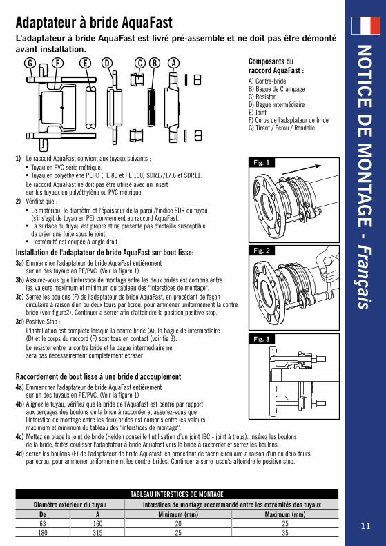
Adaptateur à bride AquaFastL'adaptateur à bride AquaFast est livré pré-assemblé et ne doit pas être démonté avant installation.
Fig. 1
Fig. 2
Fig. 3
Composants du raccord AquaFast :A) Contre-bride B) Bague de Crampage C) Resistor D) Bague intermédiaire E) Joint F) Corps de l'adaptateur de bride G) Tirant / Écrou / Rondelle
TABLEAU INTERSTICES DE MONTAGE Diamètre extérieur du tuyau Interstices de montage recommandé entre les extrémités des tuyaux
De A Minimum (mm) Maximum (mm)63 160 20 25
180 315 25 35
ABCDEFG
NO
TICE D
E M
ON
TAG
E - Français
1) Le raccord AquaFast convient aux tuyaux suivants :• Tuyau en PVC série métrique.• Tuyau en polyéthylène PEHD (PE 80 et PE 100) SDR17/17.6 et SDR11.
Le raccord AquaFast ne doit pas être utilisé avec un insert sur les tuyaux en polyéthylène ou PVC métrique.
2) Vérifiez que :• Le matériau, le diamètre et l'épaisseur de la paroi /l'indice SDR du tuyau
(s'il s'agit de tuyau en PE) conviennent au raccord AquaFast.• La surface du tuyau est propre et ne présente pas d'entaille susceptible
de créer une fuite sous le joint.• L'extrémité est coupée à angle droit
Installation de l'adaptateur de bride AquaFast sur bout lisse:3a) Emmancher l'adaptateur de bride AquaFast entièrement
sur un des tuyaux en PE/PVC. (Voir la figure 1)3b) Assurez-vous que l'interstice de montage entre les deux brides est compris entre
les valeurs maximum et minimum du tableau des "interstices de montage".3c) Serrez les boulons (F) de l'adaptateur de bride AquaFast, en procédant de façon
circulaire à raison d'un ou deux tours par écrou, pour ammener uniformement la contre bride (voir figure2). Continuer a serrer afin d'atteindre la position positive stop.
3d) Positive Stop : L'installation est complete lorsque la contre bride (A), la bague de intermediaire
(D) et le corps du raccord (F) sont tous en contact (voir fig 3). Le resistor entre la contre bride et la bague intermediaire ne
sera pas necessairement completement ecraser
Raccordement de bout lisse à une bride d'accouplement4a) Emmancher l'adaptateur de bride AquaFast entièrement
sur un des tuyaux en PE/PVC. (Voir la figure 1)4b) Alignez le tuyau, vérifiez que la bride de l'Aquafast est centré par rapport
aux perçages des boulons de la bride à raccorder et assurez-vous que l'interstice de montage entre les deux brides est compris entre les valeurs maximum et minimum du tableau des "interstices de montage".
4c) Mettez en place le joint de bride (Helden conseille l’utilisation d’un joint IBC - joint à trous). Insérez les boulons de la bride, faites coulisser l'adaptateur à bride Aquafast vers la bride à raccorder et serrez les boulons.
4d) serrez les boulons (F) de l'adaptateur de bride Aquafast, en procedant de facon circulaire a raison d'un ou deux tours par ecrou, pour ammener uniformememt les contre-brides. Continuer a serre jusqu'a atteindre le positive stop.
11
NO
TICE D
E M
ON
TAG
E - Français
Recommandations de stockage Entreposer le produit dans son emballage d'origine. Dans un environnement propre et sec avant l'installation. Assurez que le raccord Aquafast est propre et exempt de tous les débris ou contaminants avant et pendant l'installation.
Condition d’utilisation avec un tuyau pourvu d’un film de protection ou surface protectrice coloréeLorsqu'il est utilisé sur un tuyau en PE équipé d’un film de protection externe, retirer la couche de protection au-delà de la profondeur d'insertion du raccord. Cela permet de veiller à ce que l'étanchéité et le grippage ou autobutage soit faite directement sur la surface de PE et pas sur la couche extérieure de protection.
Condition d’utilisation avec un tuyau pourvu d’une barrière PE pour une utilisation dans un sol contaminé (type PE renforcé)Aquafast n'a pas été testé ou conçu pour fonctionner avec ce type de tube PE, par conséquent, nous ne recommandons pas son utilisation. Pour obtenir des conseils complémentaires, contactez les fabricants de tubes PE renforcé pour déterminer les raccords approuvés.
Condition d’utilisation avec un tuyau ovalisé et enroulé Il convient de noter que le tuyau en couronne ou touret peut présenter un degré d'ovalisation élevé; Cela peut également se produire aux tubes droits lorsqu'ils sont empilés pendant des périodes prolongées. AquaFast est un produit dédié à un diamètre spécifique et ne permet pas un haut degré d’ovalisation dans l'extrémité du tuyau. Le tuyau doit être vérifié pour déterminer son ovalisation avant utilisation et si nécessaire doit être mis au rond par un équipement approprié. Pour plus de conseils sur l'installation de ce produit, merci de contacter Helden, Département Marketing.
Fiche technique AquafastEn plus des instructions de montage, merci de prendre note également de ce qui suit lors de l'installation des produits AquaFast.
12
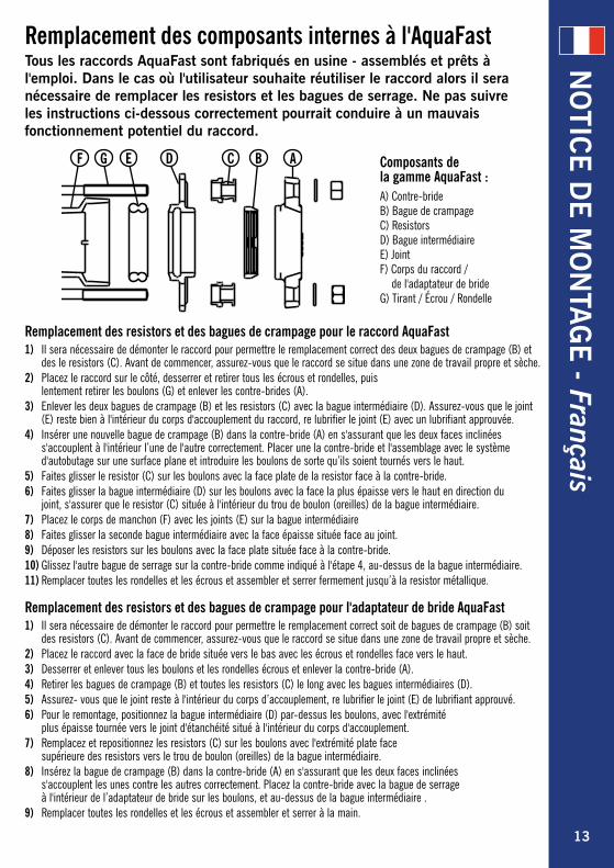
Remplacement des resistors et des bagues de crampage pour le raccord AquaFast1) Il sera nécessaire de démonter le raccord pour permettre le remplacement correct des deux bagues de crampage (B) et
des le resistors (C). Avant de commencer, assurez-vous que le raccord se situe dans une zone de travail propre et sèche.2) Placez le raccord sur le côté, desserrer et retirer tous les écrous et rondelles, puis
lentement retirer les boulons (G) et enlever les contre-brides (A).3) Enlever les deux bagues de crampage (B) et les resistors (C) avec la bague intermédiaire (D). Assurez-vous que le joint
(E) reste bien à l'intérieur du corps d'accouplement du raccord, re lubrifier le joint (E) avec un lubrifiant approuvée.4) Insérer une nouvelle bague de crampage (B) dans la contre-bride (A) en s'assurant que les deux faces inclinées
s'accouplent à l'intérieur l’une de l'autre correctement. Placer une la contre-bride et l'assemblage avec le système d'autobutage sur une surface plane et introduire les boulons de sorte qu’ils soient tournés vers le haut.
5) Faites glisser le resistor (C) sur les boulons avec la face plate de la resistor face à la contre-bride.6) Faites glisser la bague intermédiaire (D) sur les boulons avec la face la plus épaisse vers le haut en direction du
joint, s'assurer que le resistor (C) située à l'intérieur du trou de boulon (oreilles) de la bague intermédiaire.7) Placez le corps de manchon (F) avec les joints (E) sur la bague intermédiaire8) Faites glisser la seconde bague intermédiaire avec la face épaisse située face au joint.9) Déposer les resistors sur les boulons avec la face plate située face à la contre-bride.10) Glissez l'autre bague de serrage sur la contre-bride comme indiqué à l'étape 4, au-dessus de la bague intermédiaire.11) Remplacer toutes les rondelles et les écrous et assembler et serrer fermement jusqu’à la resistor métallique.
Remplacement des resistors et des bagues de crampage pour l'adaptateur de bride AquaFast1) Il sera nécessaire de démonter le raccord pour permettre le remplacement correct soit de bagues de crampage (B) soit
des resistors (C). Avant de commencer, assurez-vous que le raccord se situe dans une zone de travail propre et sèche.2) Placez le raccord avec la face de bride située vers le bas avec les écrous et rondelles face vers le haut.3) Desserrer et enlever tous les boulons et les rondelles écrous et enlever la contre-bride (A).4) Retirer les bagues de crampage (B) et toutes les resistors (C) le long avec les bagues intermédiaires (D).5) Assurez- vous que le joint reste à l'intérieur du corps d’accouplement, re lubrifier le joint (E) de lubrifiant approuvé.6) Pour le remontage, positionnez la bague intermédiaire (D) par-dessus les boulons, avec l'extrémité
plus épaisse tournée vers le joint d'étanchéité situé à l'intérieur du corps d'accouplement.7) Remplacez et repositionnez les resistors (C) sur les boulons avec l'extrémité plate face
supérieure des resistors vers le trou de boulon (oreilles) de la bague intermédiaire.8) Insérez la bague de crampage (B) dans la contre-bride (A) en s'assurant que les deux faces inclinées
s'accouplent les unes contre les autres correctement. Placez la contre-bride avec la bague de serrage à l'intérieur de l’adaptateur de bride sur les boulons, et au-dessus de la bague intermédiaire .
9) Remplacer toutes les rondelles et les écrous et assembler et serrer à la main.
Composants de la gamme AquaFast :A) Contre-bride B) Bague de crampage C) Resistors D) Bague intermédiaire E) Joint F) Corps du raccord / de l'adaptateur de bride G) Tirant / Écrou / Rondelle
Remplacement des composants internes à l'AquaFastTous les raccords AquaFast sont fabriqués en usine - assemblés et prêts à l'emploi. Dans le cas où l'utilisateur souhaite réutiliser le raccord alors il sera nécessaire de remplacer les resistors et les bagues de serrage. Ne pas suivre les instructions ci-dessous correctement pourrait conduire à un mauvais fonctionnement potentiel du raccord.
NO
TICE D
E M
ON
TAG
E - Français
ABCDEGF
13
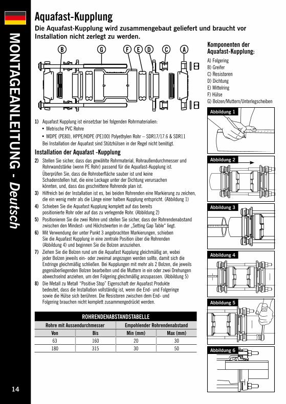
1) Aquafast Kupplung ist einsetzbar bei folgenden Rohrmaterialien: • Metrische PVC Rohre• MDPE (PE80), HPPE/HDPE (PE100) Polyethylen Rohr – SDR17/17.6 & SDR11
Bei Installation der Aquafast sind Stützhülsen in der Regel nicht benötigt.
Installation der Aquafast -Kupplung2) Stellen Sie sicher, dass das gewählte Rohrmaterial, Rohraußendurchmesser und
Rohrwandstärke (wenn PE Rohr) passend für die Aquafast-Kupplung ist. Überprüfen Sie, dass die Rohroberfläche sauber ist und keine
Schadenstellen hat, die eine Leckage unter der Dichtung verursachen könnten, und, dass das geschnittene Rohrende plan ist.
3) Hilfreich bei der Installation ist es, bei beiden Rohrenden eine Markierung zu zeichen, die ein wenig mehr als die Länge einer halben Kupplung entspricht. (Abbildung 1)
4) Schieben Sie die Aquafast Kupplung komplett auf das bereits positionierte Rohr oder auf das zu verlegende Rohr. (Abbildung 2)
5) Positionieren Sie die zwei Rohre und stellen Sie sicher, dass der Rohrendenabstand zwischen den Mindest- und Höchstwerten in der „Setting Gap Table“ liegt.
6) Mit Verwendung der unter Punkt 3 angebrachten Markierungen, schieben Sie die Aquafast Kupplung in eine zentrale Position über die Rohrenden (Abbildung 4) und beginnen Sie die Bolzen anzuziehen.
7) Ziehen Sie die Bolzen rund um die Aquafast Kupplung gleichmäßig an, wobei jeder Bolzen jeweils ein- oder zweimal angezogen werden sollte, damit sich die Endringe gleichmäßig schließen. Bei Kupplungen mit mehr als 2 Bolzen, die jeweils gegenüberliegenden Bolzen bearbeiten und die Muttern in ein oder zwei Drehungen abwechselnd anziehen, um den Folgering gleichmäßig anzupassen. (Abbildung 5)
8) Die Metall zu Metall “Positive Stop” Eigenschaft der Aquafast Produkte bedeutet, dass die Installation vollständig ist, wenn die End- und Folgeringe sowie die Hülse sich berühren. Die Resistoren zwischen dem End- und Folgering brauchen nicht komplett zusammengedrückt werden.
Aquafast-KupplungDie Aquafast-Kupplung wird zusammengebaut geliefert und braucht vor Installation nicht zerlegt zu werden.
Abbildung 1
Abbildung 3
Abbildung 4
Abbildung 6
Abbildung 5
Abbildung 2
Komponenten der Aquafast-Kupplung:A) Folgering B) Greifer C) Resistoren D) Dichtung E) Mittelring F) Hülse G) Bolzen/Muttern/Unterlegscheiben
ROHRENDENABSTANDSTABELLERohre mit Aussendurchmesser Empohlender Rohrendenabstand
Von Bis Min (mm) Max (mm)63 160 20 30
180 315 30 50
AB CDEFG
MO
NTA
GEA
NLE
ITUN
G - D
eutsch
14

Aquafast FlanschadaptorDer Aquafast-Flanschadaptor wird zusammengebaut geliefert und braucht vor Installation nicht zerlegt zu werden.
Abbildung 3
Abbildung 2
Komponenten der Aquafast-Flanschadaptor:A) Folgering B) Greifer C) Resistoren D) Mittelring E) Dichtung F) Flanschadaptorhuelse G) Bolzen/Muttern/Unterlegscheiben
ROHRENDENABSTANDSTABELLENominaler Rohraußendurchmesser Empohlender Rohrendenabstand zwischen Rohrende und Gegenflansch
Von Bis Min (mm) Max (mm)63 160 20 25
180 315 25 35
ABCDEFG
MO
NTA
GEA
NLE
ITUN
G - D
eutsch
1) Aquafast Flanschadaptor ist einsetzbar bei folgenden Rohrmaterialien: • Metrische PVC Rohre• MDPE (PE80), HPPE/HDPE (PE100) Polyethylen Rohr – SDR17/17.6 & SDR11
Bei Installation der Aquafast sind Stützhülsen in der Regel nicht benötigt.2) Stellen Sie sicher, dass das gewählte Rohrmaterial, Rohraussendurchmesser und
Rohrwandstärke (wenn PE Rohr) passend für den Aquafast-Flanschadaptor ist. Überprüfen Sie, dass die Rohroberfläche sauber ist und keine
Schadenstellen hat, die eine Leckage unter der Dichtung verursachen könnten, und, dass das geschnittene Rohrende plan ist.
Installation des Aquafast FA auf einfachem Rohrende3a) Schieben Sie den Aquafast FA komplett auf das vorhandene PE/PVC Rohr (Abbildung 1)3b) Stellen Sie sicher, dass der Rohrendenabstand zwischen Aquafast
Flansch und Rohr innerhalb der empfohlenen Werte liegt. 3c) Ziehen Sie die Bolzen rund um den Aquafast Flansch Adaptor durch jeweils ein-
oder zweimaliges Drehen gleichmäßig an, damit sich der Endring gleichmäßig schließt. Fahren Sie damit fort, bis der „Positive Stop“ erreicht ist (Abbildung 2).
3d) Die “Positve stop” Eigenschaft des Aquafast Flanschadaptors Die Metall zu Metall “Positive Stop” Eigenschaft des Aquafast Flanschadaptors
bedeutet, dass die Installation vollständig ist, wenn die End- und Folgeringe sowie der Flanschkoerper sich berühren. Die Resistoren zwischen dem End- und Folgering brauchen nicht komplett zusammengedrückt werden. (Abbildung 3)
Verbindung von einem einfachen Rohrende mit einem Gegenflansch4a) Schieben Sie den Aquafast Flanschadaptor komplett auf das PE/PVC Rohr. 4b) Richten Sie das Rohr, den Aquafast Flanschadaptor und die Gegenflansch so
aus, dass die Bolzenlöcher der Aquafast Flansch und die der Gegenflansch sich gegenüber liegen. Stellen Sie sicher, dass der Rohrendenabstand zwischen Aquafast Flansch und Rohr innerhalb der empfohlenen Werte liegt.
4c) Setzen Sie die Flanschdichtung ein (Helden empfielt die Nutzung einer Inside Bolt Circle - IBC Dichtung) und stellen Sie sicher, dass die Dichtung konzentrisch mit den Flanschverbindungsbolzen ist. Schieben Sie den Aquafast Flanschadaptor zum Gegenflansch und verschrauben Sie gemäß dem Standardverschraubungsverfahren.
4d) Ziehen Sie die Bolzen rund um den Aquafast Flansch Adaptor durch jeweils ein- oder zweimaliges Drehen gleichmäßig an, damit sich der Endring gleichmäßig schließt. Bei Flanschadaptoren mit mehr als 2 Bolzen, die jeweils gegenüberliegenden Bolzen bearbeiten und die Muttern in ein oder zwei Drehungen abwechselnd anziehen, um den Folgering gleichmäßig anzupassen bis der “Postive Stop” erreicht ist. Die Resistoren zwischen dem End- und Folgering brauchen nicht komplett zusammengedrückt werden.
Abbildung 1
15
MO
NTA
GEA
NLE
ITUN
G - D
eutsch
LagerungsanweisungLagerung des Produktes in der Originalverpackung in sauberen und trockenen Verhältnissen.
Bei Nutzung mit Rohren mit Schutzschicht oder FarbbeschichtungBei Verwendung mit PE Rohren mit externen Schutzschichten, ist diese Schicht auf der kompletten Einführlänge des Produktes zu entfernen. Dies stellt sicher, dass Rohrhalterung und –dichtung direkt auf PE-Oberfläche und nicht auf der Schutzschicht stattfinden.
Bei Nutzung mit PE Barrierenrohr bei kontaminierten GrundAquafast wurde nicht als PE Barrierenrohr konzipiert oder getestet. Aus diesem Grund können wir diese Anwendung nicht empfehlen. Hersteller dieser Rohre sollten kontaktiert werden, um Empfehlung von passenden Produkten zu erhalten.
Bei Nutzung mit Ovalrohr oder RohrschlangenBitte beachten Sie, dass Rohrschlangen in der gewickelten Form ein höheres Grad an Ovalität haben können. Dies kann auch bei geraden Rohren auftreten, wenn diese für einige Zeit gestapelt gelagert werden. Aquafast ist ein zweckbestimmtes Produkt und kann eine hohe Ovalität des Rohrendes nicht aufnehmen. Das Rohr muss vor Installation geprüft werden und eventuell mit entsprechenden Hilfsmitteln vorher abgerundet werden. Für weitere Informationen kann die Marketing Abteilung von Helden kontaktiert werden.
Aquafast ProduktinformationIn Ergänzung der Installationsanleitung bitte auch diese Informationen vor Installation der Aquafast Produkte beachten.
16

Ersetzen der Greifelemente und Resistoren der Aquafast Kupplung1) Es ist erforderlich, die Kuppung auseinander zu nehmen, um das Greifelement (B) und die Resistoren (C)
richtig einzusetzen. Bevor diese Arbeit beginnt, sollte der Arbeitsplatz sauber und trocken sein. 2) Seitliche Lagerung der Kupplung lösen und rausnehmen aller Muttern und Unterlegscheiben
und langsames Herausnehmen der Bolzen (G) und Entfernung des Endringes. (A) 3) Entfernen der Greifringe / Elemente (B) und aller Restistoren (C) zusammen mit den
Folgeringen (D). Die Dichtung (E) muss im Produktkörper verbleiben und ein geeignetes anerkanntes Schmiermittel muss neu auf die Dichtung (E) gegeben werden.
4) Einsetzten des neuen Greifelementes (B) in den Endring (A) und sicherstellen, dass beide abgewinkelte Seiten sich korrekt innerlich berühren. Ein Endring & Greifelement auf einer flachen Oberfläche platzieren und die Bolzen einsetzen, sodass die Bolzen nach oben ausgerichtet sind.
5) Schieben Sie die Resistoren (C) über die Bolzen, wobei die flache Stirnfläche des Resistoren gegenüber dem Endring ausgerichtet sein muss.
6) Schieben Sie den Folgering über die Bolzen mit der dickeren Stirnfläche nach oben zur Dichtung hin ausgerichtet, wobei die Resistoren (C) sich innerhalb der Bolzenlöcher der Metallasche befinden sollten.
7) Platzieren Sie den Produktkörper (F) mit Dichtungen (E) über den Folgering.8) Schieben Sie den zweiten Folgering mit der dickeren Stirnfläche zur Dichtung hin ausgerichtet. 9) Senken Sie die Resistoren über die Bolzen, wobei die flache Stirnseite zum Endring ausgerichtet sein soll. 10) Schieben Sie das andere Greifelement und Endring auf. Installation wie Punkt 4 auf dem Folgering. 11) Aufsetzen aller Unterlegscheiben und Muttern und ein fingerfestes Anziehen.
Ersetzen der Greifelemente und Resistoren für Aquafast Flanschadaptoren1) Es ist erforderlich, den Flanschadaptor auseinander zu nehmen um das Greifelement (B) und die Resistoren
(C) richtig einzusetzen. Bevor diese Arbeit beginnt, sollte der Arbeitsplatz sauber und trocken sein.2) Platzieren Sie den Adaptor mit der Flanschseite nach unten und die
Muttern und Unterlegscheiben nach oben ausgerichtet. 3) Rausnehmen aller Muttern und Unterlegscheiben und langsames
Herausnehmen der Bolzen und Entfernung des Endringes. (A)4) Entfernen der Greifringe / Elemente (B) und aller Restistoren (C) zusammen mit den Folgeringen (D).5) Die Dichtung muss im Produktkörper verbleiben und ein geeignetes anerkanntes
Schmiermittel muss neu auf die Dichtung (E) gegeben werden.6) Schieben Sie den Folgering über die Bolzen mit der dickeren Stirnfläche nach oben zur Dichtung hin ausgerichtet7) Ersatz und Repositonierung der Resistoren (C) über die Bolzen, wobei die flache Stirnseite zum
Endring ausgerichtet sein soll und sich die Resistoren im Folgeringbolzenloch befinden sollten. 8) Einsetzen des Greifelementes (B) in den Endring (A) und sicherstellen, das beide abgwinkelte
Seiten sich korrekt innerlich berühren. Ein Endring & Greifelement auf einer flachen Oberfläche platzieren und die Bolzen einsetzen, sodass die Bolzen nach oben ausgerichtet sind.
9) Aufsetzen aller Unterlegscheiben und Muttern und ein fingerfestes Anziehen.
Komponenten der Aqufast Produkte:A) Endring B) Greifring / Greifelement C) Resistoren D) Folgering E) Dichtung F) Produktkörper G) Bolzen
Aquafast innerer KomponentenersatzAlle Aquafast Produkte sind komplett vom Hersteller zusammengebaut geliefert. In dem Fall, dass der Benutzer das Produkt mehrmalig nutzen möchte ist es erforderlich, die Resistoren und Greifelemente zu ersetzen. Ein Nichteinhalten dieser Empfehlung kann zu einem potenziellen Produktausfall führen.
MO
NTA
GEA
NLE
ITUN
G - D
eutsch
ABCDEGF
17
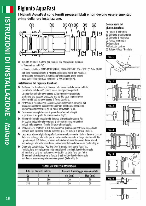
1) Il giunto AquaFast è adatto per l'uso sui tubi nei seguenti materiali:• Tubo metrico in U-PVC• Tubo in polietilene PEMD-MDPE (PE80), PEAD-HDPE (PE100) – SDR17/17.6 e SDR11
Non sono necessari inserti di rinforzo anticollassamento con AquaFast per nessuna installazione. I giunti AquaFast possono anche essere usati per collegare un tubo metrico in U-PVC ad uno in PE.
Installazione del bigiunto AquaFast:2) Verificare che il materiale, il diametro e lo spessore della parete del tubo
(se si tratta di tubo in PE) siano idonei per il giunto AquaFast. La superficie del tubo deve essere pulita e non deve presentare
graffiature che possano provocare una perdita sotto la guarnizione e l'estremità tagliata deve essere di forma quadrata.
3) Per facilitare l'installazione, contrassegnare entrambe le estremità del tubo ad una distanza leggermente superiore rispetto alla metà della lunghezza complessiva del giunto AquaFast (vedere Fig 1).
4) Fare scorrere completamente il giunto AquaFast sul tubo già in posizione o su quello da posare (vedere Fig 2).
5) Allineare i due tubi e regolare la distanza di montaggio (vedere Fig 3), assicurandosi che sia compresa tra i valori minimo e massimo indicati nella seguente ‘Tabella Distanze di montaggio’.
6) Usando i segni effettuati in (3), fare scorrere il giunto AquaFast verso la posizione centrale sulle estremità del tubo (vedere Fig. 4) ed iniziare a serrare i bulloni.
7) Lavorando attorno al giunto AquaFast, serrare uniformemente i bulloni dando a ciascun dado uno o due giri alla volta per accostare uniformemente le flange di estremità. Per i giunti con più di 2 bulloni, serrare i bulloni diametralmente opposti dando ai dadi uno o due giri alla volta accostando uniformemente l'anello terminale (vedere Fig 5).
8) Grazie alla caratteristica “Positive Stop” tra metalli del giunto AquaFast, l'installazione è completa una volta che gli anelli terminali, l'anello intermedio e il manicotto centrale risultano essere tutti in contatto l'uno con l'altro. Gli elementi di resistenza tra la flangia di estremità e l'anello intermedio non devono essere completamente compressi. (Vedere Fig 6)
Bigiunto AquaFastI bigiunti AquaFast sono forniti preassemblati e non devono essere smontati prima della loro installazione.
Fig. 1
Fig. 3
Fig. 4
Fig. 6
Fig. 5
Fig. 2
Componenti del giunto AquaFast:A) Flangia di estremità B) Elemento antisfilamento C) Elemento di resistenza D) Flangia intermedia E) Guarnizione F) Manicotto centrale G) Bullone / Dado / Rondella
TABELLA DISTANZE DI MONTAGGIO
Tubi con diametri esterni Distanze di montaggio raccomandate
Da A Min (mm) Max (mm)63 160 20 30
180 315 30 50
AB CDEFG
ISTRU
ZION
I DI IN
STALLA
ZION
E - Italiano
18

Giunto flangiato AquaFast Il giunto flangiato AquaFast è fornito preassemblato e non deve essere smontato prima della sua installazione.
Fig. 1
Fig. 2
Fig. 3
Componenti del giunto flangiato AquaFast:A) Flangia di estremità B) Elemento antisfilamento C) Elemento di resistenza D) Anello intermedio E) Guarnizione F) Corpo del giunto flangiato G) Bullone a T / Dado / Rondella
TABELLA DISTANZE DI MONTAGGIODiametro esterno tubo nominale Distanza di montaggio raccomandata tra l'estremità del tubo e la controflangia
Da A Min (mm) Max (mm)63 160 20 25
180 315 25 35
ABCDEFG
ISTRU
ZION
I DI IN
STALLA
ZION
E - Italiano
1) Il giunto flangiato AquaFast è adatto per l'uso sui tubi nei seguenti materiali:• Tubo metrico in U-PVC• Tubo in polietilene PEMD-MDPE (PE80), PEAD/HDPE (PE100) – SDR17/17.6 e SDR11
Non occorre usare inserti di rinforzo anticollassamento con AquaFast per nessuna installazione.
2) Verificare che il materiale, il diametro e lo spessore della parete del tubo (se si tratta di tubo in PE) siano idonei per il giunto flangiato AquaFast.
La superficie del tubo deve essere pulita e non deve presentare graffiature che possano provocare una perdita sotto la guarnizione e l'estremità tagliata deve essere di forma quadrata.
Installazione del giunto flangiato AquaFast su un tubo con estremità lisce:3a) Fare scorrere completamente il giunto flangiato AquaFast
sul tubo in PE / U-PVC già posato (vedere Fig 1)3b) Assicurarsi che la distanza di montaggio tra la flangia dell'AquaFast e il tubo sia compreso
tra i valori massimo e minimo raccomandati nella tabella "Distanze di montaggio".3c) Lavorando attorno al giunto flangiato AquaFast, serrare uniformemente i bulloni dando a
ciascun dado uno o due giri alla volta per accostare uniformemente la flangia terminale. Continuare a serrare fino a raggiungere la posizione “Positive Stop”. (Vedere Fig 2)
3d) Caratteristica “Positive Stop” del giunto flangiato AquaFast Grazie alla caratteristica “Positive Stop” tra i metalli del giunto flangiato
AquaFast, l'installazione è completa una volta che la flangia di estremità, l'anello intermedio ed il corpo del giunto flangiato sono tutti in contatto l'uno con l'altro. L'elemento di resistenza tra la flangia di estremità e l'anello intermedio non deve essere completamente compresso. (Vedere Fig 3)
Giunzione del tubo con estremità lisce ad una controflangia.4a) Fare scorrere completamente il giunto flangiato AquaFast sul tubo in PE / U-PVC.4b) Allineare il tubo, la flangia dell'AquaFast e la controflangia in modo che i
fori del bullone della flangia dell’Aquafast e le controflange siano allineati. Assicurarsi che la distanza di montaggio tra l'estremità del tubo e la faccia della flangia AquaFast sia compresa tra i valori massimi e minimi definiti nella "Tabella Distanze di montaggio" sottostante.
4c) Inserire la guarnizione della flangia (Helden raccomanda l'uso di una Guarnizione circolare interna per bulloni – IBC) ed assicurarsi che sia concentrica con i bulloni di connessione della flangia. Fare scorrere il giunto flangiato AquaFast verso la controflangia e serrare i bulloni usando le procedure di imbullonatura standard.
4d) Lavorando attorno al giunto flangiato AquaFast, serrare uniformemente i bulloni AquaFast dando a ciascun dado uno o due giri alla volta per accostare uniformemente la flangia di estremità. Per i giunti flangiati con più di 2 bulloni, serrare i bulloni diametralmente opposti dando a ciascun dado uno o due giri alla volta per accostare uniformemente l'anello terminale. Continuare a serrare fino ad ottenere la posizione “Positive Stop”. L'elemento di resistenza tra l'anello terminale e l'anello intermedio non deve essere completamente compresso.
19
ISTRU
ZION
I DI IN
STALLA
ZION
E - Italiano
Istruzioni per lo stoccaggio Conservare il prodotto nel suo imballo originale. In un ambiente pulito e asciutto prima dell'installazione.Assicurarsi che il giunto AquaFast sia pulito e privo di detriti o contaminanti prima e durante l'installazione.
Con un tubo provvisto di rivestimenti protettivi / rivestimenti coloratiQuando il giunto Aquafast è usato su un tubo in PE con strati di protezione esterni, rimuovere lo strato di protezione fino ad oltre la profondità di inserimento del raccordo; questo serve per assicurare che la tenuta e la presa avvengano direttamente sulla superficie in PE e non sullo strato esterno protettivo.
Con un tubo in PE dotato di strato barriera posto in un terreno contaminatoAquaFast non è stato testato né progettato per l'uso con un tubo barriera in PE, per questo motivo il suo utilizzo non è raccomandato. Richiedere le raccomandazioni del caso al produttore del tubo barriera in PE per i raccordi approvati.
Con un tubo ovale e in rotoloSi noti che il tubo in rotolo nella sua forma bloccata può presentare un grado superiore di ovalizzazione. Questo può verificarsi anche con tubi diritti quando sono impilati per periodi di tempo prolungati. AquaFast è un prodotto dedicato e non consente un elevato grado di ovalizzazione all'estremità del tubo. Prima dell'uso verificare l'estremità del tubo e, se necessario, arrotondarlo con una idonea attrezzatura.Per ulteriori informazioni sull'installazione rivolgersi al Reparto Marketing di Helden.
Note sui prodotti AquaFastOltre alle istruzioni di montaggio attenersi a quanto segue quando si installano i prodotti AquaFast.
20
Sostituzione dell'anello antisfilamento e degli elementi di resistenza del giunto AquaFast1) Sarà necessario smontare il raccordo per consentire la corretta sostituzione sia dell'anello antisfilamento interno (B)
che degli elementi di resistenza (C). Prima di iniziare, assicurarsi che il giunto sia in un'area di lavoro pulita e asciutta.2) Posizionare il giunto su di un lato, allentare e rimuovere tutti i dadi e le rondelle, quindi
ritrarre lentamente i bulloni (G) e rimuovere gli anelli terminali (A). 3) Rimuovere l'anello antisfilamento (B) e tutti gli elementi di resistenza (C) insieme agli anelli
intermedi (D). Assicurarsi che la guarnizione (E) sia rimasta all'interno del corpo del giunto, lubrificare nuovamente la guarnizione (E) con un lubrificante idoneo approvato.
4) Inserire il nuovo anello antisfilamento (B) nell'anello terminale (A) assicurandosi che all'interno entrambe le facce angolari combacino perfettamente l'una con l'altra. Collocare un gruppo anello terminale e l'anello antisfilamento su una superficie piatta, inserendo i vari bulloni in modo che siano rivolti verso l'alto.
5) Fare scorrere l'elemento di resistenza (C) sui bulloni con la faccia più piatta dell'elemento di resistenza rivolta verso l'anello terminale.
6) Fare scorrere l'anello intermedio (D) sui bulloni con la faccia più spessa rivolta verso l'alto verso la guarnizione, assicurarsi che l'elemento di resistenza (C) si trovi all'interno del foro del bullone delle staffe dell'anello intermedio.
7) Collocare il corpo del manicotto (F) con le guarnizioni (E) sull'anello intermedio.8) Fare scorrere il secondo anello intermedio con la faccia più spessa rivolta verso la guarnizione.9) Lasciar cadere gli elementi di resistenza sui bulloni con la faccia più piatta rivolta verso l'anello terminale.10) Fare scorrere l'altro gruppo anello antisfilamento ed anello terminale dalla
Fase 4 sulla parte superiore dell'anello intermedio.11) Sostituire tutte le rondelle e i dadi ed assemblarli manualmente.
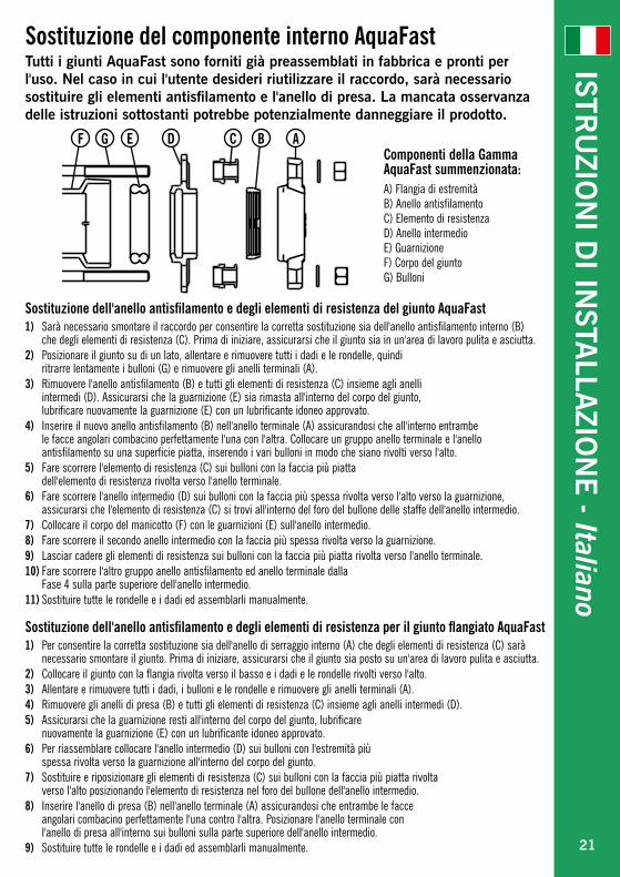
Sostituzione dell'anello antisfilamento e degli elementi di resistenza per il giunto flangiato AquaFast1) Per consentire la corretta sostituzione sia dell'anello di serraggio interno (A) che degli elementi di resistenza (C) sarà
necessario smontare il giunto. Prima di iniziare, assicurarsi che il giunto sia posto su un'area di lavoro pulita e asciutta.2) Collocare il giunto con la flangia rivolta verso il basso e i dadi e le rondelle rivolti verso l'alto.3) Allentare e rimuovere tutti i dadi, i bulloni e le rondelle e rimuovere gli anelli terminali (A).4) Rimuovere gli anelli di presa (B) e tutti gli elementi di resistenza (C) insieme agli anelli intermedi (D).5) Assicurarsi che la guarnizione resti all'interno del corpo del giunto, lubrificare
nuovamente la guarnizione (E) con un lubrificante idoneo approvato.6) Per riassemblare collocare l'anello intermedio (D) sui bulloni con l'estremità più
spessa rivolta verso la guarnizione all'interno del corpo del giunto. 7) Sostituire e riposizionare gli elementi di resistenza (C) sui bulloni con la faccia più piatta rivolta
verso l'alto posizionando l'elemento di resistenza nel foro del bullone dell'anello intermedio.8) Inserire l'anello di presa (B) nell'anello terminale (A) assicurandosi che entrambe le facce
angolari combacino perfettamente l'una contro l'altra. Posizionare l'anello terminale con l'anello di presa all'interno sui bulloni sulla parte superiore dell'anello intermedio.
9) Sostituire tutte le rondelle e i dadi ed assemblarli manualmente.
Componenti della Gamma AquaFast summenzionata:A) Flangia di estremità B) Anello antisfilamento C) Elemento di resistenza D) Anello intermedio E) Guarnizione F) Corpo del giunto G) Bulloni
Sostituzione del componente interno AquaFastTutti i giunti AquaFast sono forniti già preassemblati in fabbrica e pronti per l'uso. Nel caso in cui l'utente desideri riutilizzare il raccordo, sarà necessario sostituire gli elementi antisfilamento e l'anello di presa. La mancata osservanza delle istruzioni sottostanti potrebbe potenzialmente danneggiare il prodotto.
ISTRU
ZION
I DI IN
STALLA
ZION
E - Italiano
ABCDEGF
21
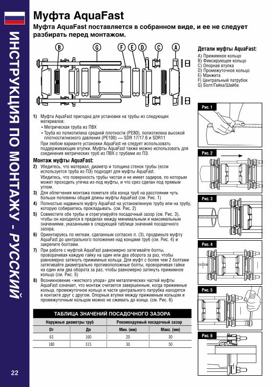
1) МуфтаAquaFastпригоднадляустановкинатрубыизследующихматериалов:•МетрическаятрубаизПВХ•Трубаизполиэтиленасреднейплотности(PE80),полиэтиленавысокой
плотности/низкогодавления(PE100)—SDR17/17.6иSDR11 ПрилюбомвариантеустановкиAquaFastнеследуетиспользовать
поддерживающиевтулки.МуфтыAquaFastтакжеможноиспользоватьдлясоединенияметрическихтрубизПВХструбамиизПЭ.
Монтаж муфты AquaFast:2) Убедитесь,чтоматериал,диаметритолщинастеноктрубы(если
используетсятрубаизПЭ)подходятдлямуфтыAquaFast. Убедитесь,чтоповерхностьтрубычистаяинеимеетзадиров,покоторым
можетпроходитьутечкаиз-подмуфты,ичтосрезсделанподпрямымуглом.
3) ДляоблегчениямонтажапометьтеобаконцатрубнарасстояниичутьбольшеполовиныобщейдлинымуфтыAquaFast(см.Рис.1)
4) ПолностьюнадвиньтемуфтуAquaFastнаустановленнуютрубуилинатрубу,которуюсобираетесьпрокладывать.(см.Рис.2)
5) Совместитеобетрубыиотрегулируйтепосадочныйзазор(см.Рис.3),чтобыоннаходилсявпределахмеждуминимальнымимаксимальнымзначениями,указаннымивследующейтаблицезначенийпосадочногозазора.
6) Ориентируясьпометкам,сделаннымсогласноп.(3),продвиньтемуфтуAquaFastдоцентральногоположениянадконцамитруб(см.Рис.4)изакрепитеболтами.
7) ПриработесмуфтойAquaFastравномернозатягивайтеболты,проворачиваякаждуюгайкунаодинилидваоборотазараз,чтобыравномернозатянутьприжимныекольца.Длямуфтсболеечем2болтамизатягивайтедиаметральнопротивоположныеболты,проворачиваягайкинаодинилидваоборотазараз,чтобыравномернозатянутьприжимноекольцо(см.Рис.5)
8) Возникновение«жесткогоупора»дляметаллическихчастеймуфтыAquaFastозначает,чтомонтажсчитаетсязавершенным,когдаприжимныекольца,промежуточноекольцоичастицентральногопатрубканаходятсявконтактедругсдругом.Опорныевтулкимеждуприжимнымкольцомипромежуточнымкольцомможнонесжиматьдоконца.(см.Рис.6)
Муфта AquaFastМуфта AquaFast поставляется в собранном виде, и ее не следует разбирать перед монтажом.
Рис. 1
Рис. 3
Рис. 4
Рис. 6
Рис. 5
Рис. 2
Детали муфты AquaFast:A)ПрижимноекольцоB)ФиксирующеекольцоC)ОпорнаявтулкаD)ПромежуточноекольцоE)МанжетаF)ЦентральныйпатрубокG)Болт/Гайка/Шайба
ТАБЛИЦА ЗНАЧЕНИЙ ПОСАДОЧНОГО ЗАЗОРА
Наружные диаметры труб Рекомендуемый посадочный зазор
От До Мин. (мм) Макс. (мм)
63 160 20 30
180 315 30 50
AB CDEFG
ИН
СТ
РУ
КЦ
ИЯ
ПО
МО
НТА
ЖУ
- РУССКИЙ
22
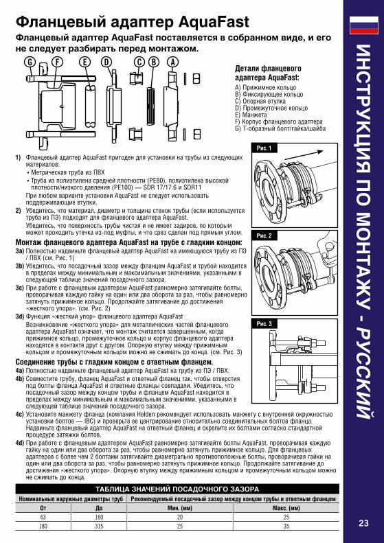
Фланцевый адаптер AquaFastФланцевый адаптер AquaFast поставляется в собранном виде, и его не следует разбирать перед монтажом.
Рис. 1
Рис. 2
Рис. 3
Детали фланцевого адаптера AquaFast:A)ПрижимноекольцоB)ФиксирующеекольцоC)ОпорнаявтулкаD)ПромежуточноекольцоE)МанжетаF)КорпусфланцевогоадаптераG)Т-образныйболт/гайка/шайба
ТАБЛИЦА ЗНАЧЕНИЙ ПОСАДОЧНОГО ЗАЗОРАНоминальные наружные диаметры труб Рекомендуемый посадочный зазор между концом трубы и ответным фланцем
От До Мин. (мм) Макс. (мм)63 160 20 25
180 315 25 35
ABCDEFG
ИН
СТ
РУ
КЦ
ИЯ
ПО
МО
НТА
ЖУ
- РУССКИЙ
1) ФланцевыйадаптерAquaFastпригодендляустановкинатрубыизследующихматериалов:•МетрическаятрубаизПВХ•Трубаизполиэтиленасреднейплотности(PE80),полиэтиленавысокой
плотности/низкогодавления(PE100)—SDR17/17.6иSDR11 ПрилюбомвариантеустановкиAquaFastнеследуетиспользовать
поддерживающиевтулки.2) Убедитесь,чтоматериал,диаметритолщинастеноктрубы(еслииспользуется
трубаизПЭ)подходятдляфланцевогоадаптераAquaFast. Убедитесь,чтоповерхностьтрубычистаяинеимеетзадиров,покоторым
можетпроходитьутечкаиз-подмуфты,ичтосрезсделанподпрямымуглом.
Монтаж фланцевого адаптера AquaFast на трубе с гладким концом:3a) ПолностьюнадвиньтефланцевыйадаптерAquaFastнаимеющуюсятрубуизПЭ
/ПВХ(см.Рис.1)3b)Убедитесь,чтопосадочныйзазормеждуфланцемAquaFastитрубойнаходится
впределахмеждуминимальнымимаксимальнымзначениями,указаннымивследующейтаблицезначенийпосадочногозазора.
3c)ПриработесфланцевымадаптеромAquaFastравномернозатягивайтеболты,проворачиваякаждуюгайкунаодинилидваоборотазараз,чтобыравномернозатянутьприжимноекольцо.Продолжайтезатягиваниедодостижения«жесткогоупора».(см.Рис.2)
3d)Функция«жесткийупор»фланцевогоадаптераAquaFast Возникновение«жесткогоупора»дляметаллическихчастейфланцевого
адаптераAquaFastозначает,чтомонтажсчитаетсязавершенным,когдаприжимноекольцо,промежуточноекольцоикорпусфланцевогоадаптеранаходятсявконтактедругсдругом.Опорнуювтулкумеждуприжимнымкольцомипромежуточнымкольцомможнонесжиматьдоконца.(см.Рис.3)
Соединение трубы с гладким концом с ответным фланцем.4a) ПолностьюнадвиньтефланцевыйадаптерAquaFastнатрубуизПЭ/ПВХ.4b) Совместитетрубу,фланецAquaFastиответныйфланецтак,чтобыотверстия
подболтыфланцаAquaFastиответныефланцысовпадали.Убедитесь,чтопосадочныйзазормеждуконцомтрубыифланцемAquaFastнаходитсявпределахмеждуминимальнымимаксимальнымзначениями,указаннымивследующейтаблицезначенийпосадочногозазора.
4c)Установитеманжетуфланца(компанияHeldenрекомендуетиспользоватьманжетусвнутреннейокружностьюустановкиболтов—IBC)ипроверьтееецентрированиеотносительносоединительныхболтовфланца.НадвиньтефланцевыйадаптерAquaFastнаответныйфланецискрепитеихболтамисогласностандартнойпроцедурезатяжкиболтов.
4d)ПриработесфланцевымадаптеромAquaFastравномернозатягивайтеболтыAquaFast,проворачиваякаждуюгайкунаодинилидваоборотазараз,чтобыравномернозатянутьприжимноекольцо.Дляфланцевыхадаптеровсболеечем2болтамизатягивайтедиаметральнопротивоположныеболты,проворачиваягайкинаодинилидваоборотазараз,чтобыравномернозатянутьприжимноекольцо.Продолжайтезатягиваниедодостижения«жесткогоупора».Опорнуювтулкумеждуприжимнымкольцомипромежуточнымкольцомможнонесжиматьдоконца.
23
ИН
СТ
РУ
КЦ
ИЯ
ПО
МО
НТА
ЖУ
- РУССКИЙ
Указания по хранению Доначаламонтажахранитеизделиеворигинальнойупаковкевсухомичистомместе.ПередмонтажомивовремянегоизделиеAquaFastдолжнобытьчистымисвободнымотлюбогозагрязнения.
При использовании с трубами с защитным многослойным / лакокрасочным покрытиемПрииспользованииструбойизПЭсвнешнимизащитнымипокрытиямиудалитезащитноепокрытиедоглубинывводафитингаидальше,чтобыгарантироватьуплотнениеизахватнепосредственноповерхностиизПЭ,аневнешнегозащитногопокрытия.
При использовании с барьерной трубой из ПЭ для применения в загрязненной почвеИзделияAquaFastнеиспытывалисьинеразрабатывалисьдляприменениясбарьернымитрубамиизПЭ,поэтомутакойвариантприменениянерекомендуется.ЗапроситеизготовителябарьернойтрубыизПЭдляинформацииорекомендуемыхфитингах.
При использовании с овальными и спиральными трубамиСледуетотметить,чтоспиральнаятрубапрификсацииможетдемонстрироватьбольшуюстепеньовальности.Этотакжевозможнодляпрямыхтрубпридлительномхранении.AquaFast—специализированноеизделие,недопускающеевысокойстепениовальностинаконцетрубы.Передмонтажомтрубунеобходимопроверитьнаовальностьипринеобходимостипридатьконцутрубыкруглуюформуприпомощиспециальногооборудования.ДляполученияболееподробныхрекомендацийпомонтажуданногоизделияобращайтесьвотделмаркетингакомпанииHelden.
Примечания по изделиям AquaFastВ дополнение к инструкциям по монтажу при установке изделий AquaFast обратите внимание на следующее.
24
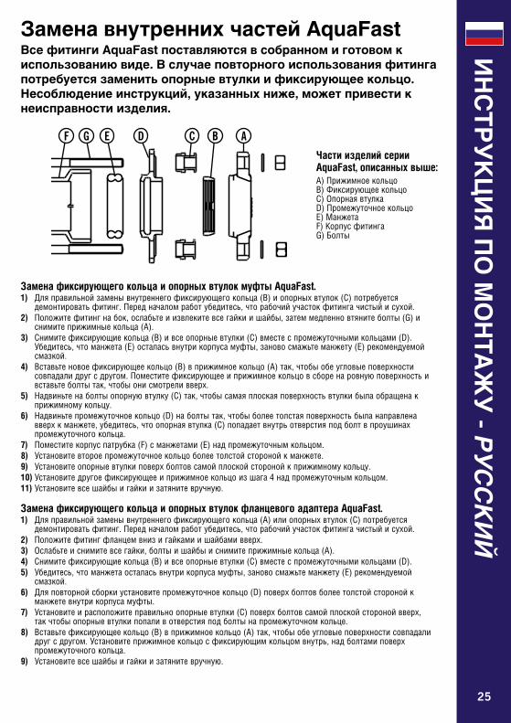
Замена фиксирующего кольца и опорных втулок муфты AquaFast.1) Дляправильнойзаменывнутреннегофиксирующегокольца(B)иопорныхвтулок(C)потребуется
демонтироватьфитинг.Передначаломработубедитесь,чторабочийучастокфитингачистыйисухой.2) Положитефитингнабок,ослабьтеиизвлекитевсегайкиишайбы,затеммедленновтянитеболты(G)и
снимитеприжимныекольца(A).3) Снимитефиксирующиекольца(B)ивсеопорныевтулки(C)вместеспромежуточнымикольцами(D).
Убедитесь,чтоманжета(E)осталасьвнутрикорпусамуфты,зановосмажьтеманжету(E)рекомендуемойсмазкой.
4) Вставьтеновоефиксирующеекольцо(B)вприжимноекольцо(A)так,чтобыобеугловыеповерхностисовпадалидругсдругом.Поместитефиксирующееиприжимноекольцовсборенаровнуюповерхностьивставьтеболтытак,чтобыонисмотреливверх.
5) Надвиньтенаболтыопорнуювтулку(C)так,чтобысамаяплоскаяповерхностьвтулкибылаобращенакприжимномукольцу.
6) Надвиньтепромежуточноекольцо(D)наболтытак,чтобыболеетолстаяповерхностьбыланаправленавверхкманжете,убедитесь,чтоопорнаявтулка(C)попадаетвнутрьотверстияподболтвпроушинахпромежуточногокольца.
7) Поместитекорпуспатрубка(F)сманжетами(E)надпромежуточнымкольцом.8) Установитевтороепромежуточноекольцоболеетолстойсторонойкманжете.9) Установитеопорныевтулкиповерхболтовсамойплоскойсторонойкприжимномукольцу.10)Установитедругоефиксирующееиприжимноекольцоизшага4надпромежуточнымкольцом.11)Установитевсешайбыигайкиизатянитевручную.
Замена фиксирующего кольца и опорных втулок фланцевого адаптера AquaFast.1) Дляправильнойзаменывнутреннегофиксирующегокольца(A)илиопорныхвтулок(C)потребуется
демонтироватьфитинг.Передначаломработубедитесь,чторабочийучастокфитингачистыйисухой.2) Положитефитингфланцемвнизигайкамиишайбамивверх.3) Ослабьтеиснимитевсегайки,болтыишайбыиснимитеприжимныекольца(A).4) Снимитефиксирующиекольца(B)ивсеопорныевтулки(C)вместеспромежуточнымикольцами(D).5) Убедитесь,чтоманжетаосталасьвнутрикорпусамуфты,зановосмажьтеманжету(E)рекомендуемой
смазкой.6) Дляповторнойсборкиустановитепромежуточноекольцо(D)поверхболтовболеетолстойсторонойк
манжетевнутрикорпусамуфты.7) Установитеирасположитеправильноопорныевтулки(C)поверхболтовсамойплоскойсторонойвверх,
такчтобыопорныевтулкипопаливотверстияподболтынапромежуточномкольце.8) Вставьтефиксирующеекольцо(B)вприжимноекольцо(A)так,чтобыобеугловыеповерхностисовпадали
другсдругом.Установитеприжимноекольцосфиксирующимкольцомвнутрь,надболтамиповерхпромежуточногокольца.
9) Установитевсешайбыигайкиизатянитевручную.
Части изделий серии AquaFast, описанных выше:A)ПрижимноекольцоB)ФиксирующеекольцоC)ОпорнаявтулкаD)ПромежуточноекольцоE)МанжетаF)КорпусфитингаG)Болты
Замена внутренних частей AquaFastВсе фитинги AquaFast поставляются в собранном и готовом к использованию виде. В случае повторного использования фитинга потребуется заменить опорные втулки и фиксирующее кольцо. Несоблюдение инструкций, указанных ниже, может привести к неисправности изделия.
ИН
СТ
РУ
КЦ
ИЯ
ПО
МО
НТА
ЖУ
- РУССКИЙ
ABCDEGF
25

Notes:
26

Notes:
27
Every effort has been made to ensure that the information contained in this publication is accurate at the time of publishing. Crane Ltd assumes no responsibility or liability for typographical errors or omissions or for any misinterpretation of the information within the publication and reserves the right to change without notice.
Se han extremado las precauciones para asegurar que la información contenida en este catálogo sea exacta en el momento de su publicación. Crane Ltd no acepta ninguna responsabilidad por errores tipográficos, omisiones o cualquier interpretación errónea de la información contenida en la publicación y se reserva el derecho de cambiarla sin previo aviso.
Toutes les précautions ont été prises pour vérifier l'exactitude des informations figurant aux présentes au moment de la publication. Crane Ltd n'accepte aucune responsabilité ni obligation relatives à des erreurs typographiques ou omissions ou à une interprétation erronée des informations figurant dans la publication et se réserve le droit de la modifier sans préavis.
Es wurden alle erforderlichen Massnahmen getroffen, um zu gewährleisten, dass zum Zeitpunkt der Herausgabe alle Informationen in dieser Publikation akurat und zutreffend sind. Crane LTD übernimmt keine Verantwortung oder Haftung für typografische Fehler, Auslassungen oder für etwaige Fehlinterpretationen innerhalb dieser Publikation und behält sich das Recht vor, Aenderungen jederzeit und ohne vorherige Ankündigung vorzunehmen.
È stato fatto ogni sforzo possibile per assicurare l'accuratezza delle informazioni qui presentate alla data di pubblicazione. Crane Ltd non si assume alcuna responsabilità per eventuali errori tipografici, omissioni o per interpretazioni errate delle informazioni presentate e si riserva il diritto di modificarle senza alcun avviso.
Все наши усилия были направлены на то, чтобы информация, содержащаяся в настоящей публикации, являлась точной на момент ее издания. “Crane Ltd” не несет ответственности за типографские ошибки или упущения в виде неправильного толкования информации в публикации, и оставляет за собой право вносить любые изменения без предварительного уведомления.
www.cranebsu.com
46-48 WILBURY WAY HITCHIN, HERTFORDSHIRE SG4 0UD. UK
TELEPHONE: +44 (0)1462 443322 FAX: +44 (0)1462 443311 EMAIL: [email protected]
DR
10
64
6_0
9_1
2_2
02
0 _
REV
05
To visit our Video Library go to: Para visitar nuestra videoteca consulte: Pour visiter notre bibliothèque vidéos se rendre à : Besuch unserer Videothek über: Per visitare la nostra videoteca andare su: ЧтобывойтивнашуВидеотекувоспользуйтесьссылкой:http://www.youtube.com/user/CraneBSUFM 00311 EMS 553775