AQUA-LATOR SURFACE AERATORS - ETEC - Aerator Catalog.pdf · Aqua-Lator aerators are used in a wide...
16
AQUA-LATOR ® SURFACE AERATORS REACTION TANKS
Transcript of AQUA-LATOR SURFACE AERATORS - ETEC - Aerator Catalog.pdf · Aqua-Lator aerators are used in a wide...
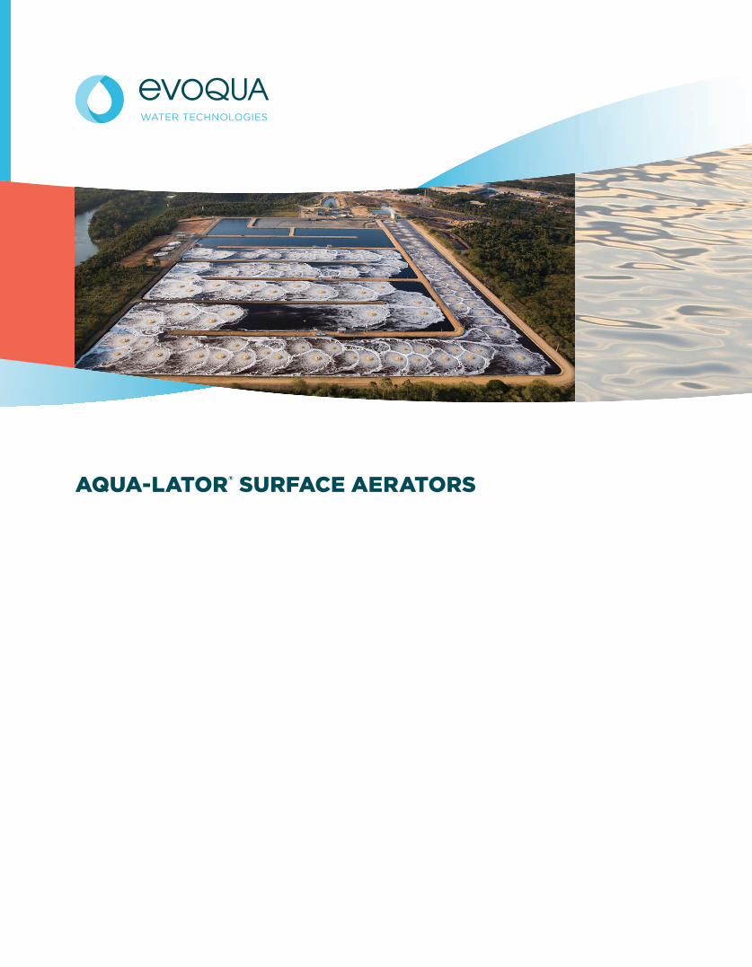
AQUA-LATOR® SURFACE AERATORS
REACTION TANKS
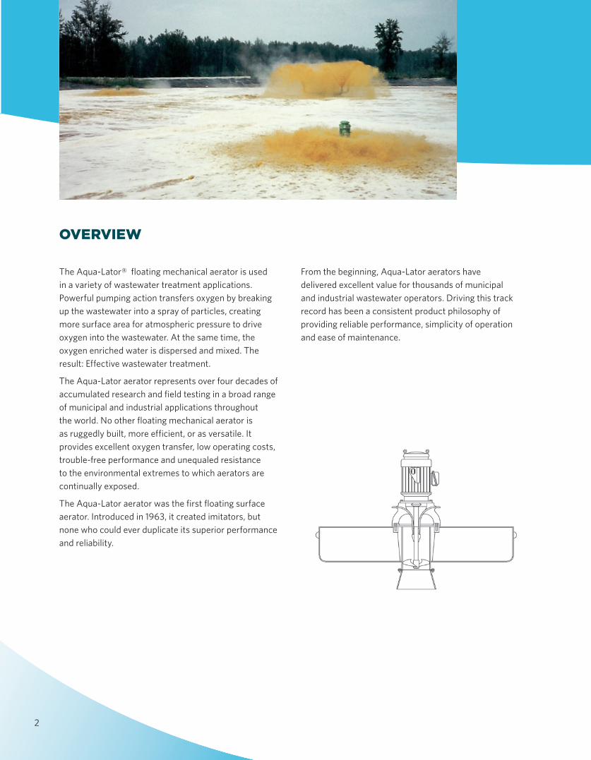
The Aqua-Lator® floating mechanical aerator is used in a variety of wastewater treatment applications. Powerful pumping action transfers oxygen by breaking up the wastewater into a spray of particles, creating more surface area for atmospheric pressure to drive oxygen into the wastewater. At the same time, the oxygen enriched water is dispersed and mixed. The result: Effective wastewater treatment.
The Aqua-Lator aerator represents over four decades of accumulated research and field testing in a broad range of municipal and industrial applications throughout the world. No other floating mechanical aerator is as ruggedly built, more effi cient, or as versatile. It provides excellent oxygen transfer, low operating costs, trouble-free performance and unequaled resistance to the environmental extremes to which aerators are continually exposed.
The Aqua-Lator aerator was the first floating surface aerator. Introduced in 1963, it created imitators, but none who could ever duplicate its superior performance and reliability.
From the beginning, Aqua-Lator aerators have delivered excellent value for thousands of municipal and industrial wastewater operators. Driving this track record has been a consistent product philosophy of providing reliable performance, simplicity of operation and ease of maintenance.
OVERVIEW
2
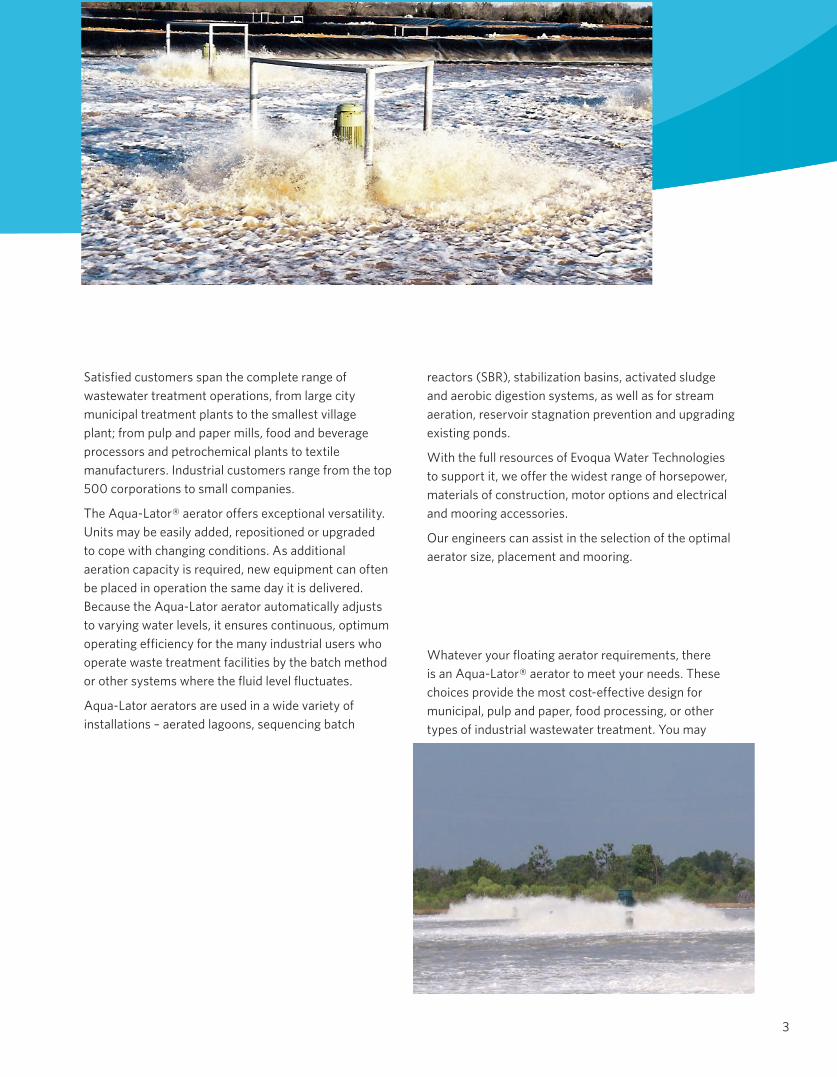
Satisfied customers span the complete range of wastewater treatment operations, from large city municipal treatment plants to the smallest village plant; from pulp and paper mills, food and beverage processors and petrochemical plants to textile manufacturers. Industrial customers range from the top 500 corporations to small companies.
The Aqua-Lator® aerator offers exceptional versatility. Units may be easily added, repositioned or upgraded to cope with changing conditions. As additional aeration capacity is required, new equipment can often be placed in operation the same day it is delivered. Because the Aqua-Lator aerator automatically adjusts to varying water levels, it ensures con tinuous, optimum operating efficiency for the many industrial users who operate waste treatment facilities by the batch method or other systems where the fluid level fluctuates.
Aqua-Lator aerators are used in a wide variety of installations – aerated lagoons, sequencing batch
reactors (SBR), stabilization basins, activated sludge and aerobic digestion systems, as well as for stream aeration, reservoir stagnation prevention and upgrading existing ponds.
With the full resources of Evoqua Water Technologies to support it, we offer the widest range of horsepower, materials of construction, motor options and electrical and mooring accessories.
Our engineers can assist in the selection of the optimal aerator size, placement and mooring.
Whatever your floating aerator requirements, there is an Aqua-Lator® aerator to meet your needs. These choices provide the most cost-effective design for municipal, pulp and paper, food processing, or other types of industrial wastewater treatment. You may
3
4
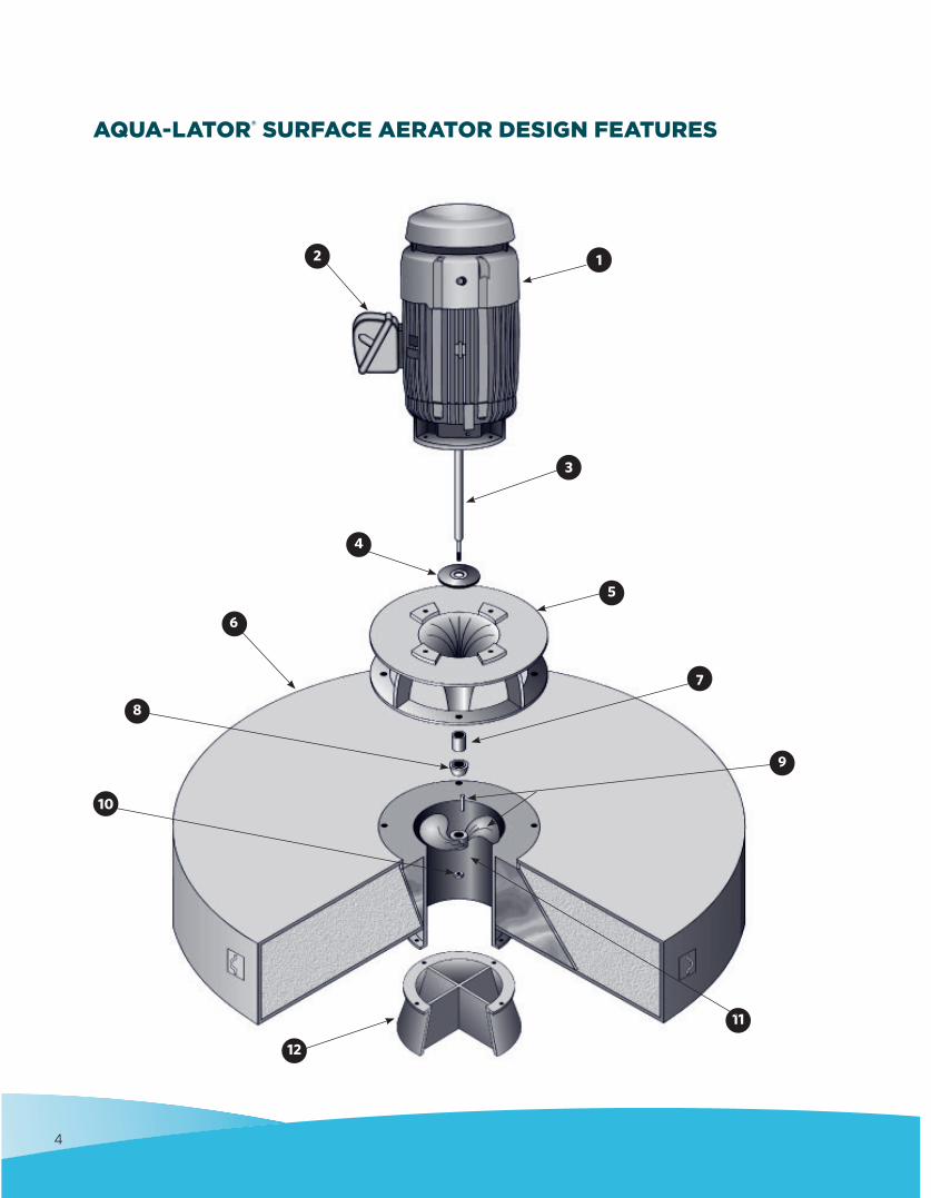
AQUA-LATOR® SURFACE AERATOR DESIGN FEATURES
11
9
7
5
3
1
4
6
8
12
10
2
MOTOR
• Totally enclosed, fan-cooled• Heavy gauge cast iron fan shield• Class F insulation• Service factor of 1.15• Standard or premium efficient available• Double-row bearings on drive end• Heavy-duty L-10, 100,000-hour bearings• Dynamically balanced and vibration tested• Designed to meet the most demanding operational
requirements
MOTOR JUNCTION BOX
• Opening in motor housing for winding leads is completely potted with epoxy filler
MOTOR SHAFT
• One piece continuous from upper bearings to the propeller
• 17-4 PH stainless steel in the 1150°F heat treated condition
• 135,000 PSI minimum yield strength• Largest diameter shaft• Threaded and keyed on drive end for simple propeller
installation
LABYRINTH SEAL GUARD
• Positioned below the bottom motor bearing to prevent moisture from migrating up the shaft into the lower bearing
DISCHARGE CONE
• Massive monolithic casting, heavier than competition• Large integral webs for rigid stability and increased
lateral strength• Designed for minimum head loss• 304 stainless steel, or cast nickel iron, epoxy-coated• Provides for lowest vibration levels• Produces maximum diffusion of water particles• 100% contact with the volute, which distributes both
static and dynamic loads
FLOAT
• Largest one-piece float available• Engineered to provide stability and better buoyancy• Fiberglass reinforced polyester (FRP), or
14-gauge, 304 stainless steel
• Filled with closed-cell polyurethane foam that adds structural stability and prevents the possibility of sinking if damage occurs to the float exterior
DEFLECTOR BEARING
• Shaft runs free under normal operating conditions• Provides support only when under load
DEBRIS DEFLECTOR
• Machined Delrin® for smooth fluid passage over the surface
• Attached with two recessed stainless steel set screws• Double engagement provides an extra measure of
preventing water migration up the shaft
PROPELLER AND KEY
• Precision investment casting• 316 stainless steel• Dynamically balanced• Keyed to mate to motor shaft in proper position• Secured to shaft by stainless steel locking nut• Simple installation or removal• Anti-fouling, non-cavitating for greater operational
efficiency
LOCKING NUT
• Stainless steel• Firmly and securely locks the propeller to the shaft• Just two tools required to install or remove the
propeller
VOLUTE
• 304 stainless steel• All sizes have bottom flange for simple bolt-on
attachment of the standard intake cone or optional anti-erosion assembly or draft tube
• Gussets at top and bottom flanges add strength
INTAKE CONE
• 304 stainless steel• Hydraulically designed for proper loading on propeller• Sufficiently sturdy to support assembled aerator on
hard, flat surface• (Optional) Anti-erosion assembly (see page 13)• (Optional) Draft Tube
5
Filled with closed-cell polyurethane foam that adds 1
2
3
4
5
6
7
8
9
10
11
12
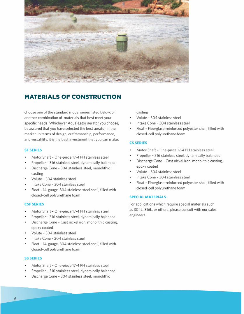
choose one of the standard model series listed below, or another combination of materials that best meet your specific needs. Whichever Aqua-Lator aerator you choose, be assured that you have selected the best aerator in the market. In terms of design, craftsmanship, performance, and versatility, it is the best investment that you can make.
SF SERIES
• Motor Shaft – One-piece 17-4 PH stainless steel• Propeller – 316 stainless steel, dynamically balanced• Discharge Cone – 304 stainless steel, monolithic
casting• Volute – 304 stainless steel• Intake Cone – 304 stainless steel• Float – 14-gauge, 304 stainless steel shell, filled with
closed-cell polyurethane foam
CSF SERIES
• Motor Shaft – One-piece 17-4 PH stainless steel• Propeller – 316 stainless steel, dynamically balanced• Discharge Cone – Cast nickel iron, monolithic casting,
epoxy coated• Volute – 304 stainless steel• Intake Cone – 304 stainless steel• Float – 14-gauge, 304 stainless steel shell, filled with
closed-cell polyurethane foam
SS SERIES
• Motor Shaft – One-piece 17-4 PH stainless steel• Propeller – 316 stainless steel, dynamically balanced• Discharge Cone – 304 stainless steel, monolithic
casting• Volute – 304 stainless steel• Intake Cone – 304 stainless steel• Float – Fiberglass-reinforced polyester shell, filled with
closed-cell polyurethane foam
CS SERIES
• Motor Shaft – One-piece 17-4 PH stainless steel• Propeller – 316 stainless steel, dynamically balanced• Discharge Cone – Cast nickel iron, monolithic casting,
epoxy coated• Volute – 304 stainless steel• Intake Cone – 304 stainless steel• Float – Fiberglass-reinforced polyester shell, filled with
closed-cell polyurethane foam
SPECIAL MATERIALS
For applications which require special materials such as 304L, 316L, or others, please consult with our sales engineers.
MATERIALS OF CONSTRUCTION
6
7
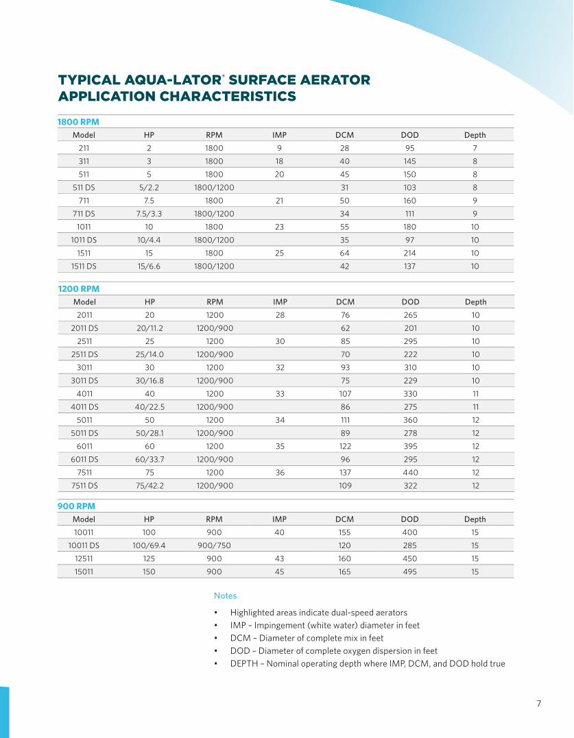
TYPICAL AQUA-LATOR® SURFACE AERATOR APPLICATION CHARACTERISTICS
Notes
• Highlighted areas indicate dual-speed aerators• IMP – Impingement (white water) diameter in feet• DCM – Diameter of complete mix in feet• DOD – Diameter of complete oxygen dispersion in feet• DEPTH – Nominal operating depth where IMP, DCM, and DOD hold true
900 RPMModel HP RPM IMP DCM DOD Depth10011 100 900 40 155 400 15
10011 DS 100/69.4 900/750 120 285 15
12511 125 900 43 160 450 15
15011 150 900 45 165 495 15
1200 RPMModel HP RPM IMP DCM DOD Depth2011 20 1200 28 76 265 10
2011 DS 20/11.2 1200/900 62 201 102511 25 1200 30 85 295 10
2511 DS 25/14.0 1200/900 70 222 103011 30 1200 32 93 310 10
3011 DS 30/16.8 1200/900 75 229 104011 40 1200 33 107 330 11
4011 DS 40/22.5 1200/900 86 275 115011 50 1200 34 111 360 12
5011 DS 50/28.1 1200/900 89 278 126011 60 1200 35 122 395 12
6011 DS 60/33.7 1200/900 96 295 127511 75 1200 36 137 440 12
7511 DS 75/42.2 1200/900 109 322 12
1800 RPMModel HP RPM IMP DCM DOD Depth
211 2 1800 9 28 95 7
311 3 1800 18 40 145 8
511 5 1800 20 45 150 8
511 DS 5/2.2 1800/1200 31 103 8
711 7.5 1800 21 50 160 9
711 DS 7.5/3.3 1800/1200 34 111 9
1011 10 1800 23 55 180 10
1011 DS 10/4.4 1800/1200 35 97 10
1511 15 1800 25 64 214 10
1511 DS 15/6.6 1800/1200 42 137 10
8
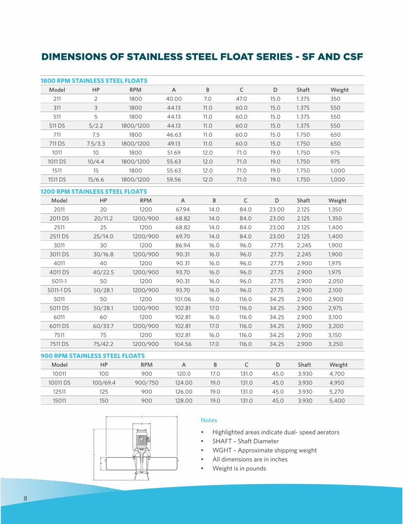
DIMENSIONS OF STAINLESS STEEL FLOAT SERIES - SF AND CSF
Notes
• Highlighted areas indicate dual- speed aerators• SHAFT – Shaft Diameter• WGHT – Approximate shipping weight• All dimensions are in inches• Weight is in pounds
900 RPM STAINLESS STEEL FLOATSModel HP RPM A B C D Shaft Weight10011 100 900 120.0 17.0 131.0 45.0 3.930 4,700
10011 DS 100/69.4 900/750 124.00 19.0 131.0 45.0 3.930 4,95012511 125 900 126.00 19.0 131.0 45.0 3.930 5,27015011 150 900 128.00 19.0 131.0 45.0 3.930 5,400
1200 RPM STAINLESS STEEL FLOATSModel HP RPM A B C D Shaft Weight2011 20 1200 67.94 14.0 84.0 23.00 2.125 1,350
2011 DS 20/11.2 1200/900 68.82 14.0 84.0 23.00 2.125 1,3502511 25 1200 68.82 14.0 84.0 23.00 2.125 1,400
2511 DS 25/14.0 1200/900 69.70 14.0 84.0 23.00 2.125 1,4003011 30 1200 86.94 16.0 96.0 27.75 2.245 1,900
3011 DS 30/16.8 1200/900 90.31 16.0 96.0 27.75 2.245 1,9004011 40 1200 90.31 16.0 96.0 27.75 2.900 1,975
4011 DS 40/22.5 1200/900 93.70 16.0 96.0 27.75 2.900 1,9755011-1 50 1200 90.31 16.0 96.0 27.75 2.900 2,050
5011-1 DS 50/28.1 1200/900 93.70 16.0 96.0 27.75 2.900 2,1005011 50 1200 101.06 16.0 116.0 34.25 2.900 2,900
5011 DS 50/28.1 1200/900 102.81 17.0 116.0 34.25 2.900 2,9756011 60 1200 102.81 16.0 116.0 34.25 2.900 3,100
6011 DS 60/33.7 1200/900 102.81 17.0 116.0 34.25 2.900 3,2007511 75 1200 102.81 16.0 116.0 34.25 2.900 3,150
7511 DS 75/42.2 1200/900 104.56 17.0 116.0 34.25 2.900 3,250
1800 RPM STAINLESS STEEL FLOATSModel HP RPM A B C D Shaft Weight
211 2 1800 40.00 7.0 47.0 15.0 1.375 350311 3 1800 44.13 11.0 60.0 15.0 1.375 550511 5 1800 44.13 11.0 60.0 15.0 1.375 550
511 DS 5/2.2 1800/1200 44.13 11.0 60.0 15.0 1.375 550711 7.5 1800 46.63 11.0 60.0 15.0 1.750 650
711 DS 7.5/3.3 1800/1200 49.13 11.0 60.0 15.0 1.750 6501011 10 1800 51.69 12.0 71.0 19.0 1.750 975
1011 DS 10/4.4 1800/1200 55.63 12.0 71.0 19.0 1.750 9751511 15 1800 55.63 12.0 71.0 19.0 1.750 1,000
1511 DS 15/6.6 1800/1200 59.56 12.0 71.0 19.0 1.750 1,000
9
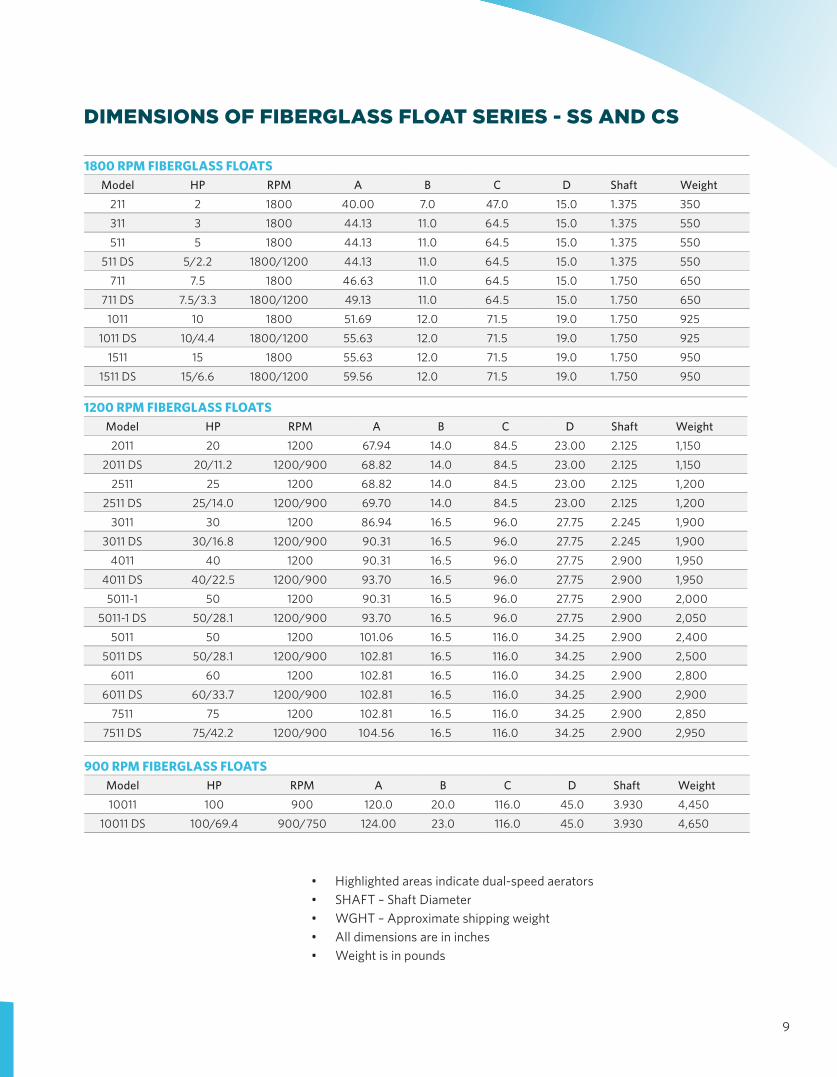
DIMENSIONS OF FIBERGLASS FLOAT SERIES - SS AND CS
• Highlighted areas indicate dual-speed aerators• SHAFT – Shaft Diameter• WGHT – Approximate shipping weight• All dimensions are in inches• Weight is in pounds
900 RPM FIBERGLASS FLOATSModel HP RPM A B C D Shaft Weight10011 100 900 120.0 20.0 116.0 45.0 3.930 4,450
10011 DS 100/69.4 900/750 124.00 23.0 116.0 45.0 3.930 4,650
1200 RPM FIBERGLASS FLOATSModel HP RPM A B C D Shaft Weight2011 20 1200 67.94 14.0 84.5 23.00 2.125 1,150
2011 DS 20/11.2 1200/900 68.82 14.0 84.5 23.00 2.125 1,1502511 25 1200 68.82 14.0 84.5 23.00 2.125 1,200
2511 DS 25/14.0 1200/900 69.70 14.0 84.5 23.00 2.125 1,2003011 30 1200 86.94 16.5 96.0 27.75 2.245 1,900
3011 DS 30/16.8 1200/900 90.31 16.5 96.0 27.75 2.245 1,9004011 40 1200 90.31 16.5 96.0 27.75 2.900 1,950
4011 DS 40/22.5 1200/900 93.70 16.5 96.0 27.75 2.900 1,9505011-1 50 1200 90.31 16.5 96.0 27.75 2.900 2,000
5011-1 DS 50/28.1 1200/900 93.70 16.5 96.0 27.75 2.900 2,0505011 50 1200 101.06 16.5 116.0 34.25 2.900 2,400
5011 DS 50/28.1 1200/900 102.81 16.5 116.0 34.25 2.900 2,5006011 60 1200 102.81 16.5 116.0 34.25 2.900 2,800
6011 DS 60/33.7 1200/900 102.81 16.5 116.0 34.25 2.900 2,900
7511 75 1200 102.81 16.5 116.0 34.25 2.900 2,850
7511 DS 75/42.2 1200/900 104.56 16.5 116.0 34.25 2.900 2,950
1800 RPM FIBERGLASS FLOATSModel HP RPM A B C D Shaft Weight
211 2 1800 40.00 7.0 47.0 15.0 1.375 350
311 3 1800 44.13 11.0 64.5 15.0 1.375 550
511 5 1800 44.13 11.0 64.5 15.0 1.375 550
511 DS 5/2.2 1800/1200 44.13 11.0 64.5 15.0 1.375 550
711 7.5 1800 46.63 11.0 64.5 15.0 1.750 650
711 DS 7.5/3.3 1800/1200 49.13 11.0 64.5 15.0 1.750 650
1011 10 1800 51.69 12.0 71.5 19.0 1.750 925
1011 DS 10/4.4 1800/1200 55.63 12.0 71.5 19.0 1.750 925
1511 15 1800 55.63 12.0 71.5 19.0 1.750 950
1511 DS 15/6.6 1800/1200 59.56 12.0 71.5 19.0 1.750 950
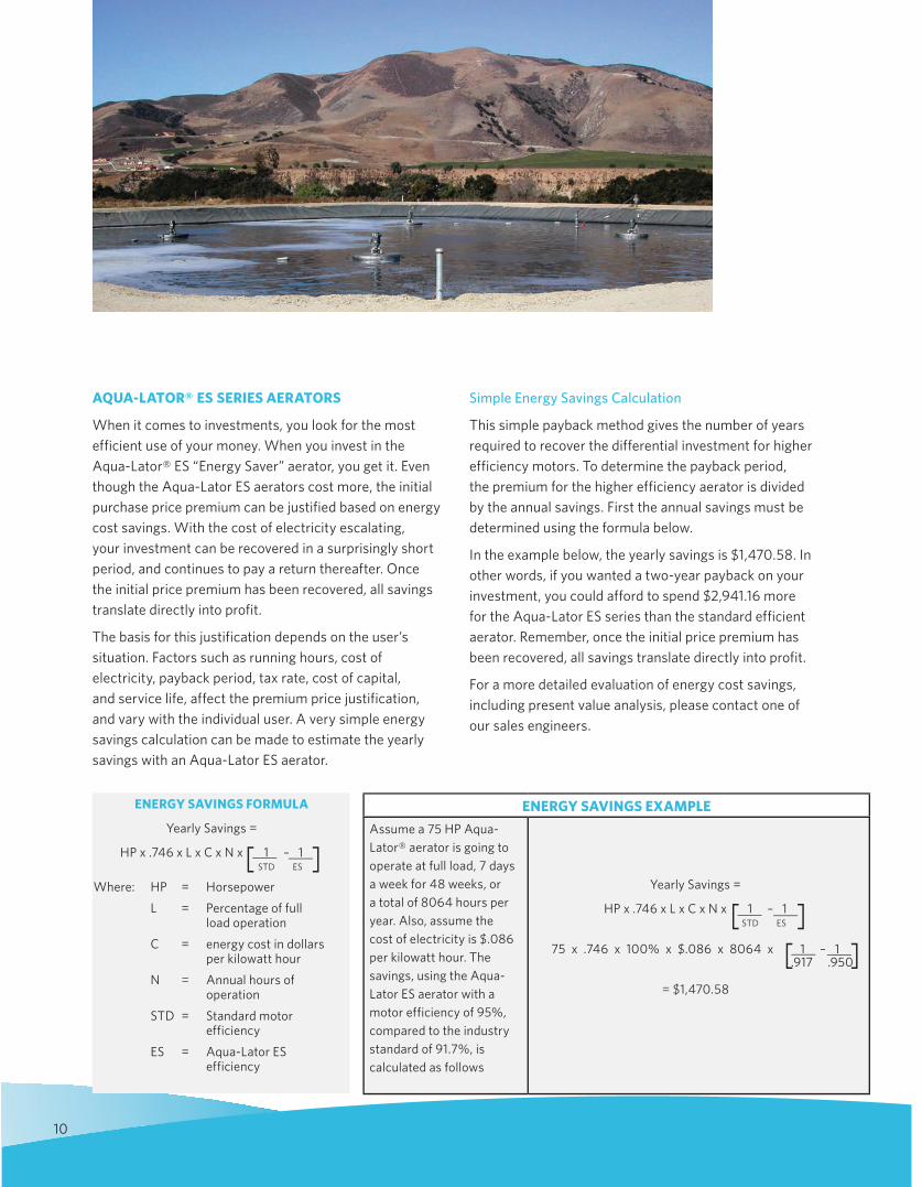
AQUA-LATOR® ES SERIES AERATORS
When it comes to investments, you look for the most efficient use of your money. When you invest in the Aqua-Lator® ES “Energy Saver” aerator, you get it. Even though the Aqua-Lator ES aerators cost more, the initial purchase price premium can be justified based on energy cost savings. With the cost of electricity escalating, your investment can be recovered in a surprisingly short period, and continues to pay a return thereafter. Once the initial price premium has been recovered, all savings translate directly into profit.
The basis for this justification depends on the user’s situation. Factors such as running hours, cost of electricity, payback period, tax rate, cost of capital, and service life, affect the premium price justification, and vary with the individual user. A very simple energy savings calculation can be made to estimate the yearly savings with an Aqua-Lator ES aerator.
Simple Energy Savings Calculation
This simple payback method gives the number of years required to recover the differential investment for higher effic iency motors. To determine the pay back period, the premium for the higher efficiency aerator is divided by the annual savings. First the annual savings must be determined using the formula below.
In the example below, the yearly savings is $1,470.58. In other words, if you wanted a two-year payback on your investment, you could afford to spend $2,941.16 more for the Aqua-Lator ES series than the standard efficient aerator. Remember, once the initial price premium has been recovered, all savings translate directly into profit.
For a more detailed evaluation of energy cost savings, including present value analysis, please contact one of our sales engineers.
10
ENERGY SAVINGS FORMULA
Yearly Savings =
HP x .746 x L x C x N x 1 – 1 STD ES
Where: HP = Horsepower
L = Percentage of full load operation
C = energy cost in dollars per kilowatt hour
N = Annual hours of operation
STD = Standard motor efficiency
ES = Aqua-Lator ES efficiency
[ ]
ENERGY SAVINGS EXAMPLE
Assume a 75 HP Aqua-Lator® aerator is going to operate at full load, 7 days a week for 48 weeks, or a total of 8064 hours per year. Also, assume the cost of electricity is $.086 per kilowatt hour. The savings, using the Aqua-Lator ES aerator with a motor efficiency of 95%, compared to the industry standard of 91.7%, is calculated as follows
Yearly Savings =
HP x .746 x L x C x N x 1 – 1 STD ES
75 x .746 x 100% x $.086 x 8064 x 1 – 1 .917 .950
= $1,470.58
[ ][ ]
11
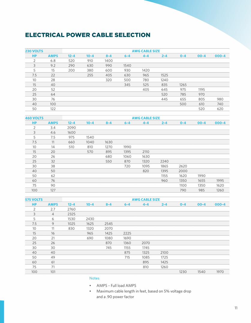
ELECTRICAL POWER CABLE SELECTION
Notes
• AMPS – Full load AMPS• Maximum cable length in feet, based on 5% voltage drop
and a .90 power factor
230 VOLTS AWG CABLE SIZEHP AMPS 12-4 10-4 8-4 6-4 4-4 2-4 0-4 00-4 000-42 6.8 520 910 14003 9.2 290 630 990 15405 15 200 380 600 930 1420
7.5 22 255 405 630 965 152510 28 320 500 780 124015 40 345 525 835 126520 52 405 645 975 119525 64 520 785 97030 76 445 655 805 98040 100 500 610 74050 122 520 620
460 VOLTS AWG CABLE SIZEHP AMPS 12-4 10-4 8-4 6-4 4-4 2-4 0-4 00-4 000-42 3.4 20903 4.6 16005 7.5 975 1540
7.5 11 660 1040 163010 14 510 810 1270 199015 20 570 895 1395 211020 26 680 1060 163025 32 550 870 1320 224030 38 720 1095 1865 262040 50 820 1395 200050 62 1155 1620 199060 76 960 1350 1655 199575 90 1100 1350 1620
100 127 790 985 1260
575 VOLTS AWG CABLE SIZEHP AMPS 12-4 10-4 8-4 6-4 4-4 2-4 0-4 00-4 000-42 2.7 27603 4 23255 6 1530 2430
7.5 9 1025 1625 254510 11 830 1320 207015 16 965 1425 222520 21 690 1080 169025 26 870 1360 207030 30 745 1155 174540 40 875 1325 210050 49 715 1085 172560 61 895 142575 71 810 1260
100 101 1230 1540 1970
12
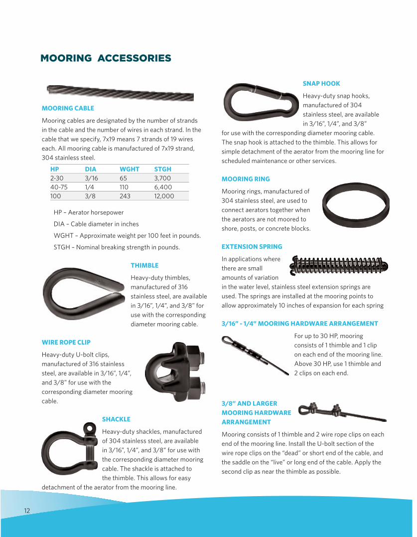
MOORING ACCESSORIES
MOORING CABLE
Mooring cables are designated by the number of strands in the cable and the number of wires in each strand. In the cable that we specify, 7x19 means 7 strands of 19 wires each. All mooring cable is manufactured of 7x19 strand, 304 stainless steel.
HP – Aerator horsepower
DIA – Cable diameter in inches
WGHT – Approximate weight per 100 feet in pounds.
STGH – Nominal breaking strength in pounds.
THIMBLE
Heavy-duty thimbles, manufactured of 316 stainless steel, are available in 3/16”, 1/4”, and 3/8” for use with the cor responding diameter mooring cable.
WIRE ROPE CLIP
Heavy-duty U-bolt clips, manufactured of 316 stainless steel, are available in 3/16”, 1/4”, and 3/8” for use with the corresponding diameter mooring cable.
SHACKLE
Heavy-duty shackles, manufac tured of 304 stainless steel, are available in 3/16”, 1/4”, and 3/8” for use with the corresponding diameter mooring cable. The shackle is attached to the thimble. This allows for easy
detachment of the aerator from the mooring line.
SNAP HOOK
Heavy-duty snap hooks, manufactured of 304 stainless steel, are available in 3/16”, 1/4”, and 3/8”
for use with the corresponding diameter mooring cable. The snap hook is attached to the thimble. This allows for simple detachment of the aerator from the mooring line for scheduled maintenance or other services.
MOORING RING
Mooring rings, manufactured of 304 stainless steel, are used to connect aerators together when the aerators are not moored to shore, posts, or concrete blocks.
EXTENSION SPRING
In applications where there are small amounts of variation in the water level, stainless steel extension springs are used. The springs are installed at the mooring points to allow approximately 10 inches of expansion for each spring
3/16” - 1/4” MOORING HARDWARE ARRANGEMENT
For up to 30 HP, mooring consists of 1 thimble and 1 clip on each end of the mooring line. Above 30 HP, use 1 thimble and 2 clips on each end.
3/8” AND LARGER MOORING HARDWARE ARRANGEMENT
Mooring consists of 1 thimble and 2 wire rope clips on each end of the mooring line. Install the U-bolt section of the wire rope clips on the “dead” or short end of the cable, and the saddle on the “live” or long end of the cable. Apply the second clip as near the thimble as possible.
HP DIA WGHT STGH2-30 3/16 65 3,70040-75 1/4 110 6,400100 3/8 243 12,000
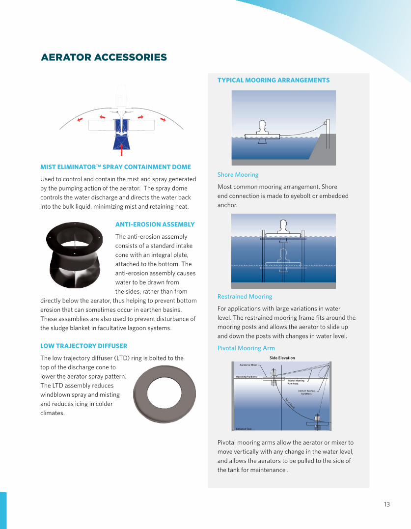
TYPICAL MOORING ARRANGEMENTS
Shore Mooring
Most common mooring arrange ment. Shore end connection is made to eyebolt or embedded anchor.
Restrained Mooring
For applications with large varia tions in water level. The restrained mooring frame fits around the mooring posts and allows the aerator to slide up and down the posts with changes in water level.
Pivotal Mooring Arm
Pivotal mooring arms allow the aerator or mixer to move vertically with any change in the water level, and allows the aerators to be pulled to the side of the tank for maintenance .
13
AERATOR ACCESSORIES
MIST ELIMINATOR™ SPRAY CONTAINMENT DOME
Used to control and contain the mist and spray generated by the pumping action of the aerator. The spray dome controls the water discharge and directs the water back into the bulk liquid, minimizing mist and retaining heat.
ANTI-EROSION ASSEMBLY
The anti-erosion assembly consists of a standard intake cone with an integral plate, attached to the bottom. The anti-erosion assembly causes water to be drawn from the sides, rather than from
directly below the aerator, thus helping to prevent bottom erosion that can sometimes occur in earthen basins. These assemblies are also used to prevent disturbance of the sludge blanket in facultative lagoon systems.
LOW TRAJECTORY DIFFUSER
The low trajectory diffuser (LTD) ring is bolted to the top of the discharge cone to lower the aerator spray pattern. The LTD assembly reduces windblown spray and misting and reduces icing in colder climates.
Side Elevation
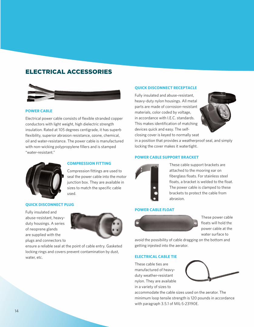
POWER CABLE
Electrical power cable consists of flexible stranded copper conductors with light weight, high dielectric strength insulation. Rated at 105 degrees centigrade, it has superb flexibility, superior abrasion resistance, ozone, chemical, oil and water-resistance. The power cable is manufactured with non-wicking polypropylene fillers and is stamped “water-resistant.”
COMPRESSION FITTING
Compression fittings are used to seal the power cable into the motor junction box. They are available in sizes to match the specific cable used.
QUICK DISCONNECT PLUG
Fully insulated and abuse-resistant, heavy-duty housings. A series of neoprene glands are supplied with the plugs and connectors to ensure a reliable seal at the point of cable entry. Gasketed locking rings and covers prevent contamination by dust, water, etc.
QUICK DISCONNECT RECEPTACLE
Fully insulated and abuse-resistant, heavy-duty nylon housings. All metal parts are made of corrosion-resistant materials, color coded by voltage, in accordance with I.E.C. standards. This makes identification of matching devices quick and easy. The self-closing cover is keyed to normally seat in a position that provides a weatherproof seal, and simply locking the cover makes it watertight.
POWER CABLE SUPPORT BRACKET
These cable support brackets are attached to the mooring ear on fiberglass floats. For stainless steel floats, a bracket is welded to the float. The power cable is clamped to these brackets to protect the cable from abrasion.
POWER CABLE FLOAT
These power cable floats will hold the power cable at the water surface to
avoid the possibility of cable dragging on the bottom and getting injested into the aerator.
ELECTRICAL CABLE TIE
These cable ties are manufactured of heavy-duty weather-resistant nylon. They are available in a variety of sizes to accommodate the cable sizes used on the aerator. The minimum loop tensile strength is 120 pounds in accordance with paragraph 3.5.1 of MIL-S-23190E.
ELECTRICAL ACCESSORIES
14
STRAIN RELIEF GRIP
Strain relief grips are designed to prevent tension from being transmitted to joints and terminals on the power cable, which could result in pull-out. In most applications, a strain relief is stronger than the cable itself and gives much greater security than the use of a compression fitting alone. Strain relief grips are available in sizes to match the specific cable used.
MOTOR OPTIONS
In addition to all the standard features on the Aqua-Lator® aerator motors, the following additional features are available:
• Premium efficient • Space Heaters • Dual speed• Thermal overload protection• Explosion-proof
CONTROL PANEL
Control panels, with NEMA® compliant enclosures are available for manual, semi-automatic, or completely automatic operation. A standard control panel consists of across-the-line starters, pushbutton start-stop switches, and a main disconnect safety lever switch. Other special enclosures which require such items as timers, pilot lights, alarm horns, or elapsed time meters, are available upon request.
SPECIAL NOTES
Specifications And Dimensions
The specifications and dimensions in this catalog are intended to be representative and illustrative, of the size, function and appearance of our products. The descriptions, data, and charts are not intended to be engineering specifications universally applicable to specific design problems. Since particular designs, installations, and plants call for specific requirements, we recommend that customers consult Evoqua for exact data and recommendations that may be required for special applications.
The Best Choice
Since establishing a leadership position in the high speed floating mechanical aerator market in 1963, the Aqua-Lator aerator has delivered excellent value to thousands of wastewater treatment operators. Going forward, the
Aqua-Lator aerator will continue to deliver reliable performance, simplicity of operation and ease of maintenance. Its exceptional versatility and usage in a wide range of wastewater applications deserves consideration from every wastewater professional. Aqua-Lator Aerators, the best choice.
The same commitments to reliable performance, product quality, and customer responsiveness support all Aqua-Lator products.
• Aqua-Lator Direct Drive Mixers• Aqua-Lator Floating Spray Coolers• E-Ball® Floating Cover Systems
15
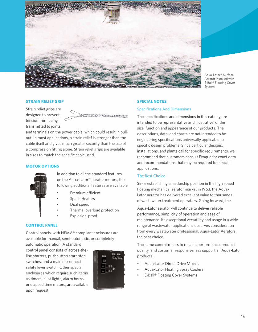
Aqua-Lator® Surface Aerator installed with E-Ball® Floating Cover System
4669 Shepherd Trail Rockford IL 61103
+1 (866) 926-8420 (toll-free) +1 (815) 623-2111 (toll) www.evoqua.com
Mist Eliminator, E-Ball and Aqua-Lator are trademarks of Evoqua, its subsidiaries or a¯liates, in some countries. NEMA is a trademark of the National Electrical Manufacturers Association. Delrin is a trademark of E. I. Du Pont de Nemours and Company.
All information presented herein is believed reliable and in accordance with accepted engineering practices. Evoqua makes no warranties as to the completeness of this information. Users are responsible for evaluating individual product suitability for specific applications. Evoqua assumes no liability whatsoever for any special, indirect or consequential damages arising from the sale, resale or misuse of its products.
© 2014 Evoqua Water Technologies LLC Subject to change without notice BC-AQUALATOR-BR-1015