Aqua-Lator High Speen Surface Aerators WW Workshop/Food Industry... · Overview THE PRODUCT The...
16
Aqua-Lator® High Speed Surface Aerators Water Technologies
Transcript of Aqua-Lator High Speen Surface Aerators WW Workshop/Food Industry... · Overview THE PRODUCT The...

Aqua-Lator® High Speed SurfaceAerators
Water Technologies

Overview
THE PRODUCT
The Aqua-Lator® aerator is a high speed floatingmechanical aerator for wastewater treatment. Powerfulpumping action transfers oxygen by breaking up thewastewater into a spray of particles, creating more surfacearea for atmospheric pressure to drive oxygen into thewastewater. At the same time, the oxygen enriched water isdispersed and mixed. The result: Effective wastewatertreatment.
The Aqua-Lator® aerator represents years of accumulatedresearch and field testing in a broad range of municipal andindustrial applications throughout the world. No otherfloating mechanical aerator is as ruggedly built, more effi-cient, or as versatile. It provides excellent oxygen transfer,low operating costs, trouble-free performance andunequaled resistance to the environmental extremes towhich aerators are continually exposed.
THE FIRST
The Aqua-Lator® aerator was the first high speed floatingaerator. Introduced in 1963, it created imitators, but nonewho could ever duplicate its superior performance andreliability.
2
EXCELLENT VALUE
From the beginning, Aqua-Lator® aerators have deliveredexcellent value for thousands of municipal and industrialwastewater operators. Driving this track record has been aconsistent product philosophy of providing reliableperformance, simplicity of operation and ease ofmaintenance.
SATISFIED CUSTOMERS
Satisfied customers span the complete range ofwastewater treatment operations, from large citymunicipal treatment plants to the smallest village plant;from pulp and paper mills, food and beverage processorsand petrochemical plants to textile manufacturers.Industrial customers range from the top 500 corporationsto small companies.

EXCEPTIONAL VERSATILITY
The Aqua-Lator® aerator offers exceptionalversatility. Units may be easily added,repositioned or upgraded to cope withchanging conditions. As additional aerationcapacity is required, new equipment canoften be placed in operation the same dayit is delivered. Because the Aqua-Lator®aerator is self-adjusting to varying waterlevels, it ensures continuous, optimumoperating efficiency for the many industrialusers who operate waste treatmentfacilities by the batch method or othersystems where the fluid level fluctuates.
BROAD RANGE OF APPLICATIONS
Aqua-Lator® aerators are used in a widevariety of installations – aerated lagoons,sequencing batch reactors (SBR),stabilization basins, activated sludge andaerobic digestion systems, as well as forstream aeration, reservoir stagnationprevention and upgrading existing ponds.
3
RESOURCES AND CAPABILITIES
We are located in a 40,000 square foot facility on 13acres in Roscoe, Illinois. Test facilities include a100,000 gallon circular tank and a 500,000 gallonsquare basin. These tanks are used for all vibrationtesting, performance evaluation and research anddevelopment programs. Our engineers can assist inthe selection of the optimal aerator size, placementand mooring.
With the full resources of Siemens WaterTechnologies to support it, we offer the widest rangeof horsepower, materials of construction, motoroptions and electrical and mooring accessories.

Aqua-Lator®AeratorDesignFeatures
21
4
6
8
10
12
3
5
7
9
11
4

MOTOR
• Totally enclosed, fan-cooled• Heavy gauge cast iron fan
shield• Class F insulation• Service factor of 1.15• Standard or energy efficient
available• Double-row bearings on drive
end• Heavy-duty L-10, 100,000-
hour bearings• Dynamically balanced and
vibration tested• Designed to meet the most
demanding operationalrequirements
MOTOR JUNCTION BOX
• Opening in motor housing forwinding leads is completelypotted with epoxy filler
MOTOR SHAFT
• One piece continuous from upper bearings to thepropeller
• 17-4 PH stainless steel in the1150°F heat treated condition
• 135,000 PSI minimum yieldstrength
• Largest diameter shaft• Threaded and keyed on drive
end for simple propellerinstallation
LABYRINTH SEAL GUARD
• Positioned below the bottommotor bearing to preventmoisture from migrating upthe shaft into the lowerbearing
DISCHARGE CONE
• Massive monolithic casting,heavier than competition
• Large integral webs for rigidstability and increased lateralstrength
• Designed for minimum headloss
• 304 stainless steel, or• Cast nickel iron, epoxy-coated• Provides for lowest vibration
levels• Produces maximum diffusion
of water particles• 100% contact with the volute,
which distributes both staticand dynamic loads
FLOAT
• Largest one-piece floatavailable
• Engineered to provide stabilityand better buoyancy
• Fiberglass reinforced polyester(FRP), or
• 14-gauge, 304 stainless steel• Filled with closed-cell
polyurethane foam that addsstructural stability andprevents the possibility ofsinking if damage occurs tothe float exterior
DEFLECTOR BEARING
• Shaft runs free under normaloperating conditions
• Provides support only whenunder load
DEBRIS DEFLECTOR
• Machined Delrin® for smoothfluid passage over the surface
• Attached with two recessedstainless steel set screws
• Double engagement providesan extra measure ofpreventing water migration upthe shaft
PROPELLER AND KEY
• Precision investment casting• 316 stainless steel• Dynamically balanced• Keyed to mate to motor shaft
in proper position• Secured to shaft by stainless
steel locking nut• Simple installation or removal• Anti-fouling, non-cavitating
for greater operationalefficiency
LOCKING NUT
• Stainless steel• Firmly and securely locks the
propeller to the shaft• Just two tools required to
install or remove the propeller
VOLUTE
• 304 stainless steel• All sizes have bottom flange
for simple bolt-on attachmentof the standard intake cone oroptional anti-erosion assemblyor draft tube
• Gussets at top and bottomflanges add strength
INTAKE CONE
• 304 stainless steel• Hydraulically designed for
proper loading on propeller• Sufficiently sturdy to support
assembled aerator on hard,flat surface
• (Optional) Anti-erosionassembly (see page 13)
• (Optional) Draft Tube (see page 13)
5
1
2
3
4
5
6
7
8
9
10
11
12
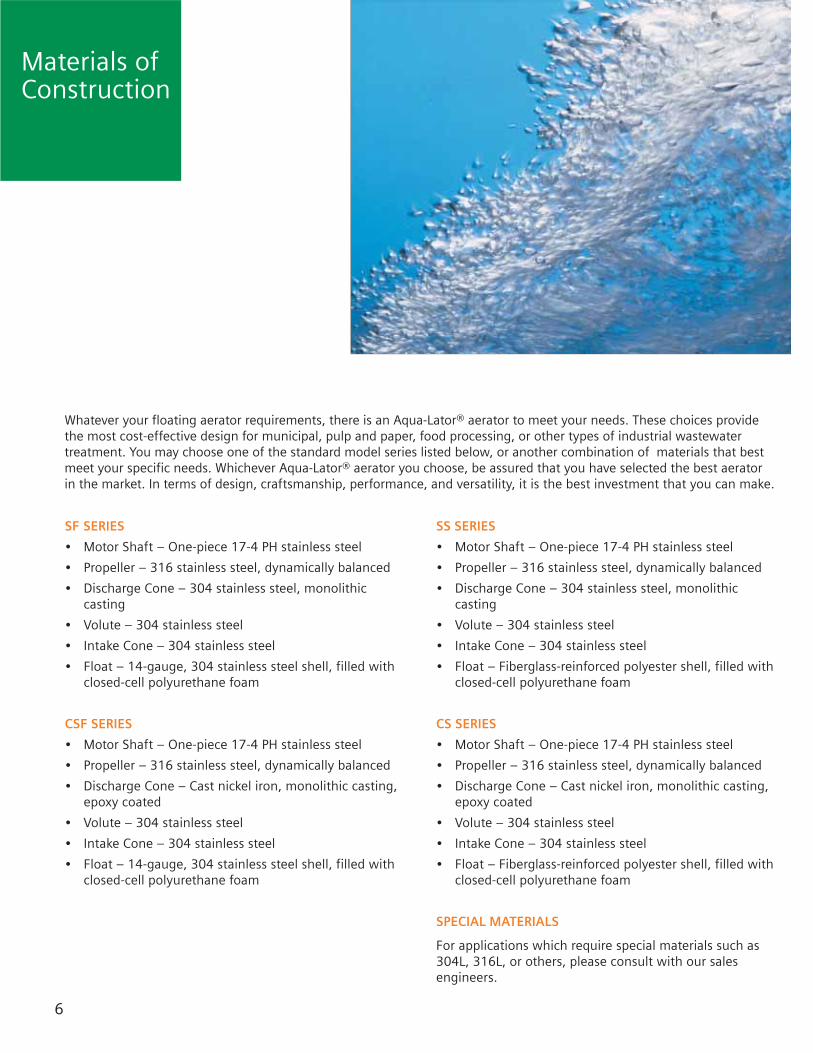
Whatever your floating aerator requirements, there is an Aqua-Lator® aerator to meet your needs. These choices providethe most cost-effective design for municipal, pulp and paper, food processing, or other types of industrial wastewatertreatment. You may choose one of the standard model series listed below, or another combination of materials that bestmeet your specific needs. Whichever Aqua-Lator® aerator you choose, be assured that you have selected the best aeratorin the market. In terms of design, craftsmanship, performance, and versatility, it is the best investment that you can make.
Materials ofConstruction
SF SERIES
• Motor Shaft – One-piece 17-4 PH stainless steel
• Propeller – 316 stainless steel, dynamically balanced
• Discharge Cone – 304 stainless steel, monolithiccasting
• Volute – 304 stainless steel
• Intake Cone – 304 stainless steel
• Float – 14-gauge, 304 stainless steel shell, filled withclosed-cell polyurethane foam
CSF SERIES
• Motor Shaft – One-piece 17-4 PH stainless steel
• Propeller – 316 stainless steel, dynamically balanced
• Discharge Cone – Cast nickel iron, monolithic casting,epoxy coated
• Volute – 304 stainless steel
• Intake Cone – 304 stainless steel
• Float – 14-gauge, 304 stainless steel shell, filled withclosed-cell polyurethane foam
SS SERIES
• Motor Shaft – One-piece 17-4 PH stainless steel
• Propeller – 316 stainless steel, dynamically balanced
• Discharge Cone – 304 stainless steel, monolithiccasting
• Volute – 304 stainless steel
• Intake Cone – 304 stainless steel
• Float – Fiberglass-reinforced polyester shell, filled withclosed-cell polyurethane foam
CS SERIES
• Motor Shaft – One-piece 17-4 PH stainless steel
• Propeller – 316 stainless steel, dynamically balanced
• Discharge Cone – Cast nickel iron, monolithic casting,epoxy coated
• Volute – 304 stainless steel
• Intake Cone – 304 stainless steel
• Float – Fiberglass-reinforced polyester shell, filled withclosed-cell polyurethane foam
SPECIAL MATERIALS
For applications which require special materials such as304L, 316L, or others, please consult with our salesengineers.
6

MODEL HP RPM IMP DCM DOD DEPTH
2011 20 1200 28 76 265 102011 DS 20/11.2 1200/900 62 201 102511 25 1200 30 85 295 102511 DS 25/14.0 1200/900 70 222 103011 30 1200 32 93 310 103011 DS 30/16.8 1200/900 75 229 104011 40 1200 33 107 330 114011 DS 40/22.5 1200/900 86 275 115011 50 1200 34 111 360 125011 DS 50/28.1 1200/900 89 278 126011 60 1200 35 122 395 126011 DS 60/33.7 1200/900 96 295 127511 75 1200 36 137 440 127511 DS 75/42.2 1200/900 109 322 12
7
MODEL HP RPM IMP DCM DOD DEPTH
211 2 1800 9 28 95 7311 3 1800 18 40 145 8511 5 1800 20 45 150 8511 DS 5/2.2 1800/1200 31 103 8711 7.5 1800 21 50 160 9711 DS 7.5/3.3 1800/1200 34 111 91011 10 1800 23 55 180 101011 DS 10/4.4 1800/1200 35 97 101511 15 1800 25 64 214 101511 DS 15/6.6 1800/1200 42 137 10
NOTES
•Highlighted areas indicate dual-speed aerators
•IMP – Impingement (white water) diameter in feet
•DCM – Diameter of complete mix in feet
•DOD – Diameter of complete oxygen dispersion in feet
•DEPTH – Nominal operating depth where IMP, DCM, and DOD hold true
1800 RPM
1200 RPM
900 RPM
Aqua-Lator®Models
MODEL HP RPM IMP DCM DOD DEPTH
10011 100 900 40 155 400 1510011 DS 100/69.4 900/750 120 285 1512511 125 900 43 160 450 1515011 150 900 45 165 495 15

NOTES
•Highlighted areas indicate dual-speed aerators
•SHAFT – Shaft Diameter
•WGHT – Approximate shipping weight
•All dimensions are in inches
•Weight is in pounds
Dimensionsof StainlessSteel FloatSeries - SFand CSF
8
MODEL HP RPM A B C D SHAFT WGHT
211 2 1800 40.00 10.5 54.0 15.00 1.375 350311 3 1800 44.13 11.0 60.0 15.00 1.375 550511 5 1800 44.13 11.0 60.0 15.00 1.375 550511 DS 5/2.2 1800/1200 44.13 11.0 60.0 15.00 1.375 550711 7.5 1800 46.63 11.0 60.0 15.00 1.750 650711 DS 7.5/3.3 1800/1200 49.13 11.0 60.0 15.00 1.750 6501011 10 1800 51.69 12.0 71.0 19.00 1.750 9751011 DS 10/4.4 1800/1200 55.63 12.0 71.0 19.00 1.750 9751511 15 1800 55.63 12.0 71.0 19.00 1.750 1,0001511 DS 15/6.6 1800/1200 59.56 12.0 71.0 19.00 1.750 1,000
MODEL HP RPM A B C D SHAFT WGHT
2011 20 1200 67.94 14.0 84.0 23.00 2.125 1,3502011 DS 20/11.2 1200/900 68.82 14.0 84.0 23.00 2.125 1,3502511 25 1200 68.82 14.0 84.0 23.00 2.125 1,4002511 DS 25/14.0 1200/900 69.70 14.0 96.0 23.00 2.125 1,4003011 30 1200 86.94 16.0 96.0 27.75 2.245 1,9003011 DS 30/16.8 1200/900 90.31 16.0 96.0 27.75 2.245 1,9004011 40 1200 90.31 16.0 96.0 27.75 2.900 1,9754011 DS 40/22.5 1200/900 93.70 16.0 96.0 27.75 2.900 1,9755011 R 50 1200 90.31 16.0 96.0 27.75 2.900 2,0505011 RDS 50/28.1 1200/900 93.70 16.0 96.0 27.75 2.900 2,1005011 50 1200 101.06 16.0 116.0 34.25 2.900 2,9005011 DS 50/28.1 1200/900 102.81 17.0 116.0 34.25 2.900 2,9756011 60 1200 102.81 16.0 116.0 34.25 2.900 3,1006011 DS 60/33.7 1200/900 102.81 17.0 116.0 34.25 2.900 3,2007511 75 1200 102.81 16.0 116.0 34.25 2.900 3,1507511 DS 75/42.2 1200/900 104.56 17.0 116.0 34.25 2.900 3,250
MODEL HP RPM A B C D SHAFT WGHT
10011 100 900 120.00 17.0 131.0 45.00 3.930 4,70010011 DS 100/69.4 900/750 124.00 19.0 131.0 45.00 3.930 4,95012511 125 900 126.00 19.0 131.0 45.00 3.930 5,27015011 150 900 128.00 19.0 131.0 45.00 3.930 5,400
1800 RPM STAINLESS STEEL FLOATS
1200 RPM STAINLESS STEEL FLOATS
900 RPM STAINLESS STEEL FLOATS
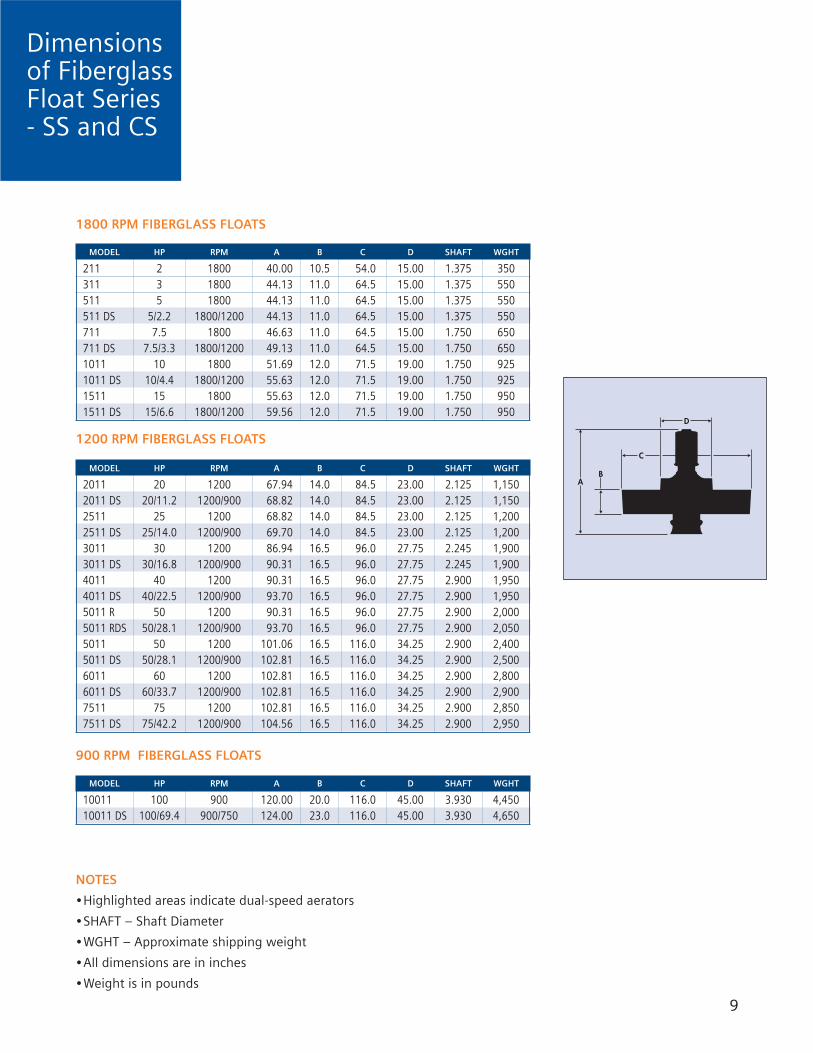
NOTES
•Highlighted areas indicate dual-speed aerators
•SHAFT – Shaft Diameter
•WGHT – Approximate shipping weight
•All dimensions are in inches
•Weight is in pounds
9
MODEL HP RPM A B C D SHAFT WGHT
211 2 1800 40.00 10.5 54.0 15.00 1.375 350311 3 1800 44.13 11.0 64.5 15.00 1.375 550511 5 1800 44.13 11.0 64.5 15.00 1.375 550511 DS 5/2.2 1800/1200 44.13 11.0 64.5 15.00 1.375 550711 7.5 1800 46.63 11.0 64.5 15.00 1.750 650711 DS 7.5/3.3 1800/1200 49.13 11.0 64.5 15.00 1.750 6501011 10 1800 51.69 12.0 71.5 19.00 1.750 9251011 DS 10/4.4 1800/1200 55.63 12.0 71.5 19.00 1.750 9251511 15 1800 55.63 12.0 71.5 19.00 1.750 9501511 DS 15/6.6 1800/1200 59.56 12.0 71.5 19.00 1.750 950
MODEL HP RPM A B C D SHAFT WGHT
2011 20 1200 67.94 14.0 84.5 23.00 2.125 1,1502011 DS 20/11.2 1200/900 68.82 14.0 84.5 23.00 2.125 1,1502511 25 1200 68.82 14.0 84.5 23.00 2.125 1,2002511 DS 25/14.0 1200/900 69.70 14.0 84.5 23.00 2.125 1,2003011 30 1200 86.94 16.5 96.0 27.75 2.245 1,9003011 DS 30/16.8 1200/900 90.31 16.5 96.0 27.75 2.245 1,9004011 40 1200 90.31 16.5 96.0 27.75 2.900 1,9504011 DS 40/22.5 1200/900 93.70 16.5 96.0 27.75 2.900 1,9505011 R 50 1200 90.31 16.5 96.0 27.75 2.900 2,0005011 RDS 50/28.1 1200/900 93.70 16.5 96.0 27.75 2.900 2,0505011 50 1200 101.06 16.5 116.0 34.25 2.900 2,4005011 DS 50/28.1 1200/900 102.81 16.5 116.0 34.25 2.900 2,5006011 60 1200 102.81 16.5 116.0 34.25 2.900 2,8006011 DS 60/33.7 1200/900 102.81 16.5 116.0 34.25 2.900 2,9007511 75 1200 102.81 16.5 116.0 34.25 2.900 2,8507511 DS 75/42.2 1200/900 104.56 16.5 116.0 34.25 2.900 2,950
MODEL HP RPM A B C D SHAFT WGHT
10011 100 900 120.00 20.0 116.0 45.00 3.930 4,45010011 DS 100/69.4 900/750 124.00 23.0 116.0 45.00 3.930 4,650
1800 RPM FIBERGLASS FLOATS
1200 RPM FIBERGLASS FLOATS
900 RPM FIBERGLASS FLOATS
Dimensionsof FiberglassFloat Series- SS and CS
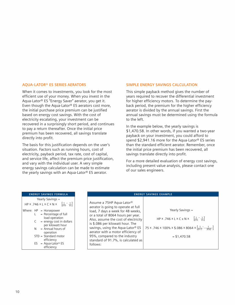
ENERGY SAVINGS FORMULA
Yearly Savings =
HP x .746 x L x C x N x [ 1 - 1 ]STD ES
Where: HP = HorsepowerL = Percentage of full
load operationC = energy cost in dollars
per kilowatt hourN = Annual hours of
operationSTD = Standard motor
efficiencyES = Aqua-Lator® ES
efficiency
AQUA-LATOR® ES SERIES AERATORS
When it comes to investments, you look for the mostefficient use of your money. When you invest in theAqua-Lator® ES “Energy Saver” aerator, you get it.Even though the Aqua-Lator® ES aerators cost more,the initial purchase price premium can be justifiedbased on energy cost savings. With the cost ofelectricity escalating, your investment can berecovered in a surprisingly short period, and continuesto pay a return thereafter. Once the initial pricepremium has been recovered, all savings translatedirectly into profit.
The basis for this justification depends on the user’ssituation. Factors such as running hours, cost ofelectricity, payback period, tax rate, cost of capital,and service life, affect the premium price justification,and vary with the individual user. A very simpleenergy savings calculation can be made to estimatethe yearly savings with an Aqua-Lator® ES aerator.
10
ENERGY SAVINGS EXAMPLE
Assume a 75HP Aqua-Lator®aerator is going to operate at fullload, 7 days a week for 48 weeks,or a total of 8064 hours per year.Also, assume the cost of electricityis $.086 per kilowatt hour. Thesavings, using the Aqua-Lator® ESaerator with a motor efficiency of95%, compared to the industrystandard of 91.7%, is calculated asfollows:
Yearly Savings =
HP x .746 x L x C x N x [ 1 - 1 ]STD ES
75 x .746 x 100% x $.086 x 8064 x [ 1 - 1 ].917 .950
= $1,470.58
SIMPLE ENERGY SAVINGS CALCULATION
This simple payback method gives the number ofyears required to recover the differential investmentfor higher efficiency motors. To determine the pay-back period, the premium for the higher efficiencyaerator is divided by the annual savings. First theannual savings must be determined using the formulato the left.
In the example below, the yearly savings is$1,470.58. In other words, if you wanted a two-yearpayback on your investment, you could afford tospend $2,941.16 more for the Aqua-Lator® ES seriesthan the standard efficient aerator. Remember, oncethe initial price premium has been recovered, allsavings translate directly into profit.
For a more detailed evaluation of energy cost savings,including present value analysis, please contact oneof our sales engineers.

NOTES
•AMPS – Full load AMPS
•Maximum cable length in feet, based on 5% voltage drop and a .90 powerfactor 11
HP AMPS 12-4 10-4 8-4 6-4 4-4 2-4 0-4 00-4 000-4
2 6.8 520 910 14003 9.2 290 630 990 15405 15 200 380 600 930 1420
7.5 22 255 405 630 965 152510 28 320 500 780 124015 40 345 525 835 126520 52 405 645 975 119525 64 520 785 97030 76 445 655 805 98040 100 500 610 74050 122 520 620
A W G C A B L E S I Z E
HP AMPS 12-4 10-4 8-4 6-4 4-4 2-4 0-4 00-4 000-4
2 3.4 20903 4.6 16005 7.5 975 1540
7.5 11 660 1040 163010 14 510 810 1270 199015 20 570 895 1395 211020 26 680 1060 163025 32 550 870 1320 224030 38 720 1095 1865 262040 50 820 1395 200050 62 1155 1620 199060 76 960 1350 1655 199575 90 1100 1350 1620
100 127 790 985 1260
A W G C A B L E S I Z E
HP AMPS 12-4 10-4 8-4 6-4 4-4 2-4 0-4 00-4 000-4
2 2.7 27603 4 23255 6 1530 2430
7.5 9 1025 1625 254510 11 830 1320 207015 16 965 1425 222520 21 690 1080 169025 26 870 1360 207030 30 745 1155 174540 40 875 1325 210050 49 715 1085 172560 61 895 142575 71 810 1260
100 101 1230 1540 1970
A W G C A B L E S I Z E
ElectricalPower CableSelection
230 VOLTS
460 VOLTS
575 VOLTS

12
MOORING CABLE
Mooring cables are designated by thenumber of strands in the cable andthe number of wires in each strand. Inthe cable that we specify, 7x19 means7 strands of 19 wires each. Allmooring cable is manufactured of7x19 strand, 304 stainless steel.
HP DIA WGHT STGH
2-30 3/16 65 3,70040-75 1/4 110 6,400100 3/8 243 12,000
HP – Aerator horsepowerDIA – Cable diameter in inchesWGHT – Approximate weight per 100feet in pounds.STGH – Nominal breaking strength inpounds.
THIMBLE
Heavy-duty thimbles, manufacturedof 316 stainless steel, are available in3/16”, 1/4”, and 3/8” for use with thecorresponding diameter mooringcable.
WIRE ROPE CLIP
Heavy-duty U-bolt clips, manufacturedof 316 stainless steel, are available in3/16”, 1/4”, and 3/8” for use with thecorresponding diameter mooringcable.
SHACKLE
Heavy-duty shackles, manufactured of 304 stainless steel, are available in 3/16”, 1/4”, and 3/8” for use with the corresponding diameter mooringcable. The shackle is attached to thethimble. This allows for easydetachment of the aerator from the mooring line.
EXTENSION SPRING
In applications where there are smallamounts of variation in the waterlevel, stainless steel extension springsare used. The springs are installed atthe mooring points to allowapproximately 10 inches of expansionfor each spring
3/16” - 1/4” MOORING HARDWAREARRANGEMENT
For up to 30 HP, mooring consists of 1thimble and 1 clip on each end of themooring line. Above 30 HP, use 1thimble and 2 clips on each end.
3/8” AND LARGER MOORINGHARDWARE ARRANGEMENT
Mooring consists of 1 thimble and 2wire rope clips on each end of themooring line. Install the U-bolt sectionof the wire rope clips on the “dead” orshort end of the cable, and the saddleon the “live” or long end of the cable.Apply the second clip as near thethimble as possible.
SNAP HOOK
Heavy-duty snap hooks, manufacturedof 304 stainless steel, are available in3/16”, 1/4”, and 3/8” for use with thecorresponding diameter mooringcable. The snap hook is attached tothe thimble. This allows for simpledetachment of the aerator from themooring line for scheduledmaintenance or other services.
MOORING RING
Mooring rings, manufactured of 304stainless steel, are used to connectaerators together when the aeratorsare not moored to shore, posts, orconcrete blocks.
MooringAccessories

13
Typical MooringArrangements
LOW TRAJECTORY DIFFUSER
This fiberglass ring is bolted to the top of the discharge cone to lower the aerator spray pattern. In colderclimates, this will help reduce thewindblown spray and minimize icing.
ANTI-ICE DIFFUSER
This cast aluminum ring is bolted tothe top of the discharge cone tominimize ice build-up. The ringcontains heating cable and rangesfrom 1000 to 5000 watts, based onthe horsepower of the aerator. Theanti-ice diffuser is equipped with anintegral junction box which containsthe automatic thermostat. The anti-icediffuser requires its own 2-conductorelectrical power cable for operation.
ANTI-EROSION ASSEMBLY
The anti-erosion assembly consists ofa standard intake cone with anintegral plate, sized for that particularhorsepower. These antierosionassemblies are available in stainlesssteel or epoxy coated steel. Thisassembly causes water to be drawnfrom the sides, rather than fromdirectly below the aerator, thushelping to prevent bottom erosionthat can sometimes occur in earthenbasins. These assemblies are also usedto prevent disturbance of the sludgeblanket in facultative lagoon systems.
DRAFT TUBE
The draft tube is simply an extensionof the intake cone to allow for adeeper intake of water in specificcustomer applications to promotecomplete oxygen dispersion andsolids suspension. Draft tubes areavailable in stainless steel or epoxy-coated steel. Deep basins, in whichthe depth is more than 1.5 times thelength of the shortest wall, mayrequire anti-vortex precautions whendraft tubes are used.
SHORE MOORING
Most common mooring arrangement.Shore end connection is made toeyebolt or embedded anchor.
RESTRAINED MOORING
For applications with large variationsin water level. A triangular frame withthree rings is attached to the float.These rings, which are removableU-bolts, fit around three posts,permitting the unit to slide up anddown the posts with varying waterlevels.
AeratorAccessories

14
POWER CABLE
Electrical power cable consists offlexible stranded copper conductorswith light weight, high dielectricstrength insulation. Rated 105degrees centigrade, it has superbflexibility, superior abrasionresistance, ozone, chemical, oil andwater-resistance. The power cable ismanufactured with non-wickingpolypropylene fillers and is stamped“water-resistant.”
COMPRESSION FITTING
Compression fittings are used to sealthe power cable into the motorjunction box. They are available insizes to match the specific cable used.
QUICK DISCONNECT PLUG
Fully insulated and abuse-resistant,heavy-duty housings. A series ofneoprene glands are supplied withthe plugs and connectors to ensure areliable seal at the point of cableentry. Gasketed locking rings andcovers prevent contamination bydust, water, etc.
QUICK DISCONNECT RECEPTACLE
Fully insulated and abuse-resistant,heavy-duty nylon housings. All metalparts are made of corrosion-resistantmaterials, color coded by voltage, inaccordance with I.E.C. standards. Thismakes identification of matchingdevices quick and easy. The self-closing cover is keyed to normally seatin a position that provides aweatherproof seal, and simply lockingthe cover makes it watertight.
ELECTRICAL CABLE TIE
These cable ties are manufactured ofheavy-duty weather-resistant nylon.They are available in a variety of sizesto accommodate the cable sizes usedon the aerator. The minimum looptensile strength is 120 pounds inaccordance with paragraph 3.5.1 ofMIL-S-23190E.
STRAIN RELIEF GRIP
Strain relief grips are designed toprevent tension from beingtransmitted to joints and terminals onthe power cable, which could resultin pull-out. In most applications, astrain relief is stronger than the cableitself and gives much greater securitythan the use of a compression fittingalone. Strain relief grips are availablein sizes to match the specific cableused.
POWER CABLE SUPPORTBRACKET
These cable support brackets areattached to the mooring ear onfiberglass floats. For stainless steelfloats, a bracket is welded to thefloat. The power cable is clamped tothese brackets to protect the cablefrom abrasion.
POWER CABLE FLOAT
These power cable floats will hold thepower cable at the water surface toavoid the possibility of cable draggingon the bottom and getting injestedinto the aerator.
ElectricalAccessories

15
CONTROL PANEL
Control panels, with NEMA®compliant enclosures, are available formanual, semi-automatic, orcompletely automatic operation. Astandard control panel consists ofacross-the-line starters, pushbuttonstart-stop switches, and a maindisconnect safety lever switch. Otherspecial enclosures which require suchitems as timers, pilot lights, alarmhorns, or elapsed time meters, areavailable upon request.
MOTOR OPTIONS
In addition to all the standard featureson the Aqua-Lator® aerator motors,the following additional features areavailable:
• Dual-speed• ES “Energy Saver”• Space heaters• Thermal overload protection• Explosion-proof• Special OSHA colors
Special NotesSPECIFICATIONS AND DIMENSIONS
The specifications and dimensions in thiscatalog are intended to be representativeand illustrative, of the size, function andappearance of our products. Thedescriptions, data, and charts are notintended to be engineering specificationsuniversally applicable to specific designproblems. Since particular designs, installa-tions, and plants call for specific require-ments, we recommend that customersconsult Siemens for exact data andrecommendations that may be required forspecial applications.
WARNING
The Aqua-Lator® aerator has a very highvelocity flow directly beneath the aerator,which may cause damage to the basinbottoms or walls, creating leaking potentialand/or ground water contamination.Siemens recommends the use of a concretepad or other durable material that is knownto be resistant to the wastewater, to beplaced on the basin bottom directlybeneath the aerator. In addition, precau-tions should be taken to protect the basinwalls. Siemens assumes no liability for anydamages to the basin bottoms or walls orany injuries resulting from this application.
DANGER
The Aqua-Lator® aerator was not designed,nor intended for workers to service theaerator by standing on the float. Failure tokeep off the aerator may result in injuriesand/or drowning. Siemens does notrecommend standing on any size aerator,and assumes no liability for any injuries ordeath resulting therefrom.
ElectricalAccessories
THE BEST CHOICE
Since establishing a leadershipposition in the high speed floatingmechanical aerator market in 1963,the Aqua-Lator® aerator hasdelivered excellent value tothousands of wastewater treatmentoperators. Going forward, the Aqua-Lator® aerator will continue todeliver reliable performance,simplicity of operation and ease ofmaintenance. Its exceptionalversatility and usage in a wide rangeof wastewater applications deservesconsideration from every wastewaterprofessional. Aqua-Lator® Aerators,the best choice.
The same commitments to reliableperformance, product quality andcustomer responsiveness support allAqua-Lator® products,
• AERATORS
• DDM MIXERS
• FOUNTAIN AERATORS
• FLOATING SPRAY COOLERS

The information provided in this brochure contains merelygeneral descriptions or characteristics of performance which
in actual case of use do not always apply as described orwhich may change as a result of further development of the
products. An obligation to provide the respectivecharacteristics shall only exist if expressly agreed in the terms
of the contract.
NEMA is a trademark of the National ElectricalManufacturers Association
Delrin is a trademark of E. I. Du Pont de Nemours and Company
Aqua-Lator is a trademark of Siemens, its subsidiaries oraffiliates.
©2006 Siemens Water Technologies Corp.Printed in the U.S.A.
AP-GEN-BR-0107Subject to change without prior notice.
For more information please contact:
Siemens Water Technologies
11765 Main StreetRoscoe, IL 61073Tel: 815.623.2111Fax: 815.623.6416www.usfilter.com