
Aqua Drive System - JFPA · conventional term above; ... paper machines Fire fighting and ......
48
Aqua Drive System - A Technical Guide 2 Japan Fluid Power Association
Transcript of Aqua Drive System - JFPA · conventional term above; ... paper machines Fire fighting and ......

Aqua Drive Sys - A Technical
Japan Fluid Power Assoc
� �
���tem Guide 2
iation

Copyright © 2005 by Japan Fluid Power Association
Front cover: Copyright © Town of Asakura, Fukuoka Prefecture, Japan. Triple water mills, a national registered monument
Back cover: Fukuroda-no-taki, Ibaragi Prefecture, Japan

Releasing the 2nd edition of the ADS Technical Guide
Concepts such as sustainability, safety, cleanliness, and hygiene have come to keys essential for developing new technologies in recent years. They have been important in domains of environmental protection and industrial wastes in particular; the global communities have discussed on CO2 emissions, dioxin pollution, soil contamination, and water pollution from green perspectives while the industries have concerned about the 3R approach (Reduce, Reuse, Recycle), that are closely linked to industrial waste treatment. Today, however, those topics are no longer limited to those domains, and efforts for solving the problems have been widely spread. The field of engineering is not an exception. Re-evaluation of not only machines and their drives (oil hydraulics, pneumatics and electrics) but also overall service requirements and environment has already been started in the light of environmental and social sustainability.
Japan Fluid Power Association, or JFPA, found the movement very important and has launched projects, "Technical Study on Environmental Friendly Water Hydraulic Drive Systems" from 1998 to 2000, and subsequently "Research and Study for the Practical Use of the Aqua Drive Technology" from 2001 to 2003. These projects were made possible with the Machinery Promotion Fund by Japan Motorcycle Racing Organization. The study outcome is the "Aqua Drive System (ADS) technology," a new fluid power drive that solely uses "tap water" as the power transmission medium. The ADS technology has increasingly been gaining attention in the United States and Europe as an alternative to conventional solutions.
The three-year project, "Technical Study on Environmental Friendly Water Hydraulic Drive Systems,”
released an English version of the first ADS technical guide, "Aqua Drive System - A Technical Guide" in the year 2000, and the copies were distributed at HANNOVER MESSE 2001 in April 2001. The Guide was intended to promote the ADS technology and to offer a common ground for both component and system suppliers to refer when they jointly develop water hydraulic applications. The project members made a presentation on their water hydraulic technology at the Joint Water Hydraulic Committee Meeting during the MESSE. To respond to a strong demand for the Japanese version from the JFPA members and those who are interested in water hydraulics, the Guide was translated in to Japanese in 2001. Finally, this 2nd edition of the Guide (English version) was released in 2005 as the summary of the ADS technology studied and gained in the six-year research. We wish this 2nd edition of the ADS Technical Guide be beneficial for people who are interested and contribute to progress of the ADS technology in the world.
We would like to express our deep appreciation to the Industrial Machinery Division of Manufacturing
Industrial Bureau, Ministry of Economy, Trade and Industries and Japan Motorcycle Racing Organization for their valuable inputs and sincere support. March 2005
Japan Fluid Power Association Kenichi Hirano, Chairman of the Technical Committee, Atsushi Yamaguchi, Chairman of the Study Committee on ADS for Practical Applications
- Table of Contents - Chapter 1 Approaches Toward Application of ADS.......................1
Chapter 2 Guide for Selecting ADS Components..........................3 2.1 List of components and suppliers ................................................................................. 3 2.2 Types and specifications ............................................................................................... 6
2.2.1 Overview of water hydraulic components......................................................... 6 2.2.2 Specifications of water hydraulic components ............................................... 10
2.3 Materials for components and systems ...................................................................... 16
Chapter 3 Water Quality Control for Aqua Drive System ............18 3.1 Water quality................................................................................................................ 18 3.2 Water quality evaluation test ....................................................................................... 18
3.2.1 Test apparatus and conditions........................................................................ 18 3.2.2 Test result........................................................................................................ 19
3.3 Guidelines for water quality control............................................................................. 21
Chapter 4 Operating Aqua Drive System .....................................23 4.1 High-speed operation.................................................................................................. 23
4.1.1 Experimental apparatus and method ............................................................. 23 4.1.2 Experimental results ....................................................................................... 25 4.1.3 Simulation ....................................................................................................... 29
4.2 ADS operational guideline........................................................................................... 32 4.2.1 Pressure loss and flow rate ............................................................................ 32 4.2.2 Surge pressure prevention ............................................................................. 33 4.2.3 System configuration and operational considerations.................................... 34
Chapter 5 Application of Aqua Drive System ..............................36 5.1 Applicable fields of ADS.............................................................................................. 36 5.2 Published ADS applications ........................................................................................ 37
Chapter 6 Future Perspectives of Aqua Drive System................40 6.1 Social demand and ADS............................................................................................. 40 6.2 Market and prospects of ADS ..................................................................................... 40 6.3 Boosting the ADS-related industries ........................................................................... 41
JFPA Water Hydraulics Committee Members: Companies and Universities........................42
“Technical Study on Environmental Friendly Water Hydraulic Drive Systems” from 1998 to 2000 “Research and Study for the Practical Use of the Aqua Drive Technology” from 2001 to 2003

Chapter 1 Approaches Toward Application of ADS Fluid power technology that uses water for power transmission has already been utilized at the end of the 18th century. The technology of the time was focused more on transmitting a huge power. However, it involved many problems, such as low efficiency due to leakage and material deterioration resulted from wear, friction, and rust. All these were blamed on low viscosity of water. Not to mention, nothing was done to treat and maintain the working water. Later, various kinds of water-based fluids, of which rust-prevention, corrosion resistance, and lubricating properties have been improved by adding additives to water, have begun to be used for press and mining machines. The major advantage offered by these fluids is flame resistance; therefore, they have been well applied to iron manufacture facilities where the danger of fire was the most concern. A water hydraulic drive system is often recognized just as "water hydraulics" in a boarder sense, and most likely, it uses water-based fluids. The “Aqua Drive System (ADS)" in this technical guide, on the contrary, is differently defined from the conventional term above; it solely uses tap water or pure water for its power transmission. ADS is not a substitution of existing system drives: it is a solution for various systems to maximize their overall advantages while minimizing risks inherent in use of conventional oil hydraulic, pneumatic, or electric drives.
Advantages (1) Availability: The readily available tap water is
the system fluid. (2) Easy to dispose of: The used water can be
damped to the rivers and sewage without special wastewater process or can be recycled as required.
(3) Low management cost: Costs for purchase and management of the fluid are low.
(4) Low environmental impact: Even upon an accidental leakage during the operation, the fluid is non-odorous, non-toxic, and harmless.
(1) Oil-free ・ The aqua drive system consists of components
without lubricating oil, working oil, and mechanical oil.
・ The driving characteristics of the aqua drive system are equivalent to those of the conventional driving technologies, such as by electricity, oil hydraulics, and pneumatics.
(2) Life Cycle Assessment (LCA) compliant The concept to evaluate the viability of the system ・ Resource and energy saving. ・ Environmental conservation, cleanliness
required for the environmentally sustainable manufacturing process, safety in hygiene.
・ Overall cost performance, including the initial cost but also service, maintenance, and management costs, etc.
(3) High technology supported ・ Today's cutting-edge fundamental technologies
in the fields of ceramics, engineering plastics, and advanced surface treatment technology.
Fig. 1.1 Three elements supporting aqua drive technology
・ Computer-aided technologies in design and analysis, as well as in control and management.
Fig. 1.2 Environmentally sustainable aqua drive system
1

(5) Superior compatibility with products: The system is very clean, and hygiene control is easy. (6) Fire resistance: ADS uses water, a fire-resistant fluid. This ensures fire safety and makes the system
excluded from objects to which the Fire Defense Law is to be applied; the system is superior to any other driving system in regards to fire insurance and safety management.
(7) Low pressure loss: Water's low viscosity contributes to reduction of pipe pressure loss and easy system expansion. Because of this, the user can even save power required when compared to that required for the oil hydraulic system of the same size.
(8) High response: High fluid stiffness provides rapid power transmission.
Potential application fields of ADS
Special environmental area
Sanitation HACCP
Machines for food processing, beverage
bottling, packaging General production and manufacture lines
Work environment
Machines in radio active areas
in-water/in-ocean
Natural environment conservation
Oceanfront, river, and lake
construction machines
Machines for semiconductors,
electric parts, etc.
Cleanliness
Optical, medical, pharmaceutical,
precision molding, and paper machines
Fire fighting and rescue tools
Welfare/universal house equipment
Leisure complex, sports, and amusement park
equipment
Safety/prevention on explosion
Safety on in-house/amusement area
Machines for high temp./explosive
areas (steel, rolling, volatile
areas )
Factory-basis water hydraulic net system/emission-free production process
(Resource and energy saving)
ISO 14001 OHSAS 18001
ISO 12001ISO 9001
Incorporationof high-technology
Water treatment
Adva
nced
com
pute
r
appl
icatio
n
Incr
ease
d re
liabi
lity
Hig
h-pr
ecis
ion
pr
oces
sing
Hig
h-le
vel
surf
ace
trea
tmen
t
Application of new
materials
Bimetallic junction
Oil-free machinery elements,such as bearing, gear, ball screw,
speed reducer, etc.
ADS Technology (Aqua Drive System)
Fig. 1.3 Applicable fields of ADS and their supporting technologies
Problems to be solved (1) Lubrication property and sealing characteristic: Water's low viscosity deteriorates the lubrication
property, leading to decreased efficiency by leakage from slight gaps of the system components or by increase of wear and friction on the mating faces of moving parts and deteriorated sealing.
(2) Cavitation prevention: Water’s high vapor pressure easily initiates cavitation and erosion, which cause material deterioration.
(3) Rust prevention: Rust is easy to be generated. (4) Water quality maintenance: In the fluid, bacteria, sludge, and slime are developed. Metal
compounds are deposited.
These problems unique to the "aqua drive system" can be solved through careful selection of component structures/materials and by use of advanced designing methods with computers. Applying today's high-end technology is also beneficial for the materials and the surface treatment.
2

Chapter 2 Guide for Selecting ADS Components
2.1 List of components and suppliers Figure 2.1 lists the categories of the ADS components.
AquaDriveSystem
Pumps
Actuators
Valves
Piping, Hosing, Fitting
Tanks
Accessories
Controllers
PositiveDisplacement
Centrifugal
Motors
Cylinders
Rotary
DirectionalPressureFlowServo & Proportional
FiltersAccumulatorsHeat exchangersWater quality control unitsSensorsOthers
AxialRadialVaneTurbine
AxialRadialVaneReciprocal
Fig. 2.1 Devices and accessories that configure ADS Table 2.1 lists suppliers of water hydraulic components and accessories for ADS in Japan. As of September 2003, 64 companies either manufacture or supply water hydraulic products: 59 of those are the member companies of JFPA and 5 are non-member companies. The water hydraulic components in Table 2.1 are selected based on Fig. 2.1 and the component lists included in our publication, Fluid Power Industry in Japan. The pump category, centrifugal pump, is omitted from the tables and no supplier/product information on the item is given this time. A valve category “Cartridge valve” is added to the table. Accessories such as sensors and pressure switches are included in “Measuring instruments.” “Heat exchangers” include coolers. “Fittings” and “Piping Materials” are grouped as one category in the tables. “Others” include gauge cocks, surge dampers, and mechanical seals. The category, “Water-base fluid,” although included in listed in Fluid Power Industry in Japan, is omitted in Table 2.1. The symbols indicate availability of the listed water hydraulic components: for production, ○ or ●, and for sales only, △ or ▲. The data of the component manufacturers and suppliers in the following pages are made based on the data in Fluid Power Industry in Japan, questionnaires and study of product catalogues of the members from 2002 to 2004 by our Water Hydraulics Committee. The symbols indicate availability of brief specifications of the items in Tables 2.2 to 2.7 in Section 2.2.2. Only the components of the responders to our questionnaires or surveys are listed in the following tables.
3

4
Table 2.1 Water hydraulic component manufacturers and suppliers (1/2)
Water Hydraulic Component and Accessory Products
Company (64 in total)
Posi
tive
disp
lace
men
t pum
ps
Mot
ors
Cyl
inde
rs
Wat
er h
ydra
ulic
Ja
cks
Pres
sure
con
trol
valv
es
Flow
con
trol v
alve
s
Dire
ctio
nal v
alve
s
Car
tridg
e va
lves
Prop
ortio
nal v
alve
s
Serv
o va
lves
Accu
mul
ator
s
Pres
sure
Inte
nsifi
ers
Mea
surin
g in
stru
men
ts
Filte
rs
Hea
t exc
hang
ers
Pow
er u
nits
Fitti
ngs
& Pi
ping
mat
eria
ls
Hos
es
Pack
ing
Oth
ers
Mem
bers
hip
ARAKI IRON WORKS LTD. ○ ▲ A IHARA SCIENCE CORPORATION ○ ● ● ▲ ▲ ● F EATON FLUID POWER LTD. ▲ ▲ F ASK CORPORTION ● ● ▲ ● F SMC CORPORATION ○ ○ ○ ● ● ● F EBARA RESEARCH CO., LTD. △ ○ △ △ △ △ ○ ○ ○ A NOK CORPORATION ○ ● F OIL DRIVE KOGYO LTD. ● ● F OHSAKA INDUSTRIES CO., LTD. ● ▲ F OSAKA JACK CO., LTD. ○ ● ○ ▲ ▲ F OHTSUKA CO., LTD. ● A KATSUMA STEEL TUBE CO., LTD. ● A KAMUI CO., LTD. ● F KAYABA INDUSTRY CO., LTD. ○ ○ ● ● F KAWAJYU SHOJI CO., LTD. ▲ ▲ ▲ ▲ A KITAMURA SHOKO CO., LTD. ○ △ ○ ○ △ △ △ △ ▲ ▲ △ ○ ▲ ● ▲ ○ ▲ ▲ ▲ ▲ A KOSHIN SEIKOSHO, LTD. ○ A KOKUSAI KOGYO CO., LTD. ▲ ▲ ▲ ▲ ▲ ▲ ▲ ▲ ▲ ▲ ▲ ▲ ▲ ▲ ▲ ▲ ▲ ▲ ▲ A KOYO CO., LTD. ▲ F KOYO SEIKI CO., LTD. ● F SAKAGAMI SEISAKUSHO LTD. ● F SANMAX CORPORATION ● ○ ○ ○ ○ ● ▲ ▲ ▲ CKD CORPORATION ● ● ● F JAPAN PNEUMATICS CO., LTD. ○ △ JUNKOSHA CO., LTD. ● ● A SHINTO BRATOR, LTD. ● A NIPPON STEEL CORPORATIN ● A SUGINO MACHINE LTD ○ ○ ○ ○ ▲ ● ▲ SUMITOMO PRECISION PRODUCTS CO., LTD. ● F TAIYO, LTD. ○ ○ ● F TAIYO INTERNATIONAL CORPORATION △ △ △ △ ▲ ▲ ▲ △ ▲ ▲ F TAKAKO INDUSTRIES INC. ● ● F DANFOSS K.K. △ △ △ △ △ △ △ ▲ △
Note 1) ○ & ●: components for production. △ & ▲: components for sales. Brief specifications of the products, only with
○ or △, are available in Tables 2.2 to 2.7 in Section 2.2.2. Note 2) These tables are compiled based on Table of Products in Fluid Power Industry in Japan issued in September 2004
and results of the survey conducted by the Committee. Note 3) The “Membership” indicates the statues: ”F” for a full membership and “A” for an associate membership. Note 4) Water hydraulic technology developed by Ebara Research Co., Ltd. has been transferred to Takako Industries Inc., a
full member of Japan Fluid Power Association.

5
Table 2.1 Water hydraulic component manufacturers and suppliers (2/2)
Water Hydraulic Equipment and Accessory Products
Company (64 in total)
Posi
tive
disp
lace
men
t pum
ps
Mot
ors
Cyl
inde
rs
Wat
er h
ydra
ulic
jack
s
Pres
sure
con
trol
valv
es
Flow
con
trol v
alve
s
Dire
ctio
nal v
alve
s
Car
tridg
e va
lves
Prop
ortio
nal v
alve
s
Serv
o va
lves
Accu
mul
ator
s
Pres
sure
inte
nsifi
ers
Mea
surin
g in
stru
men
ts
Filte
rs
Hea
t exc
hang
ers
Pow
er u
nits
Fitti
ngs
& Pi
ping
mat
eria
l
Hos
es
Pack
ing
Oth
ers
Mem
bers
hip
TOWA KIKI CO., LTD. △ ○ △ △ △ ▲ ▲ ○ ▲ ▲ ▲ TOKIMEC INC. △ F TOKAI RUBBER INDUSTRIES LTD. ● ● A TOHTO HYDRAULICS CORPORATION △ △ △ ▲ △ △ △ △ △ ▲ ▲ ▲ ▲ A TOYOOKI KOGYO CO., LTD. ● ○ ○ ● ● ○ ● F NAKANISHI SHOJI CO., LTD. ▲ ▲ ▲ A NAKAMURA KOKI CO., LTD. ● ▲ F NABCO LTD. ○ ○ △ ▲ ● F NIKKO INDUSTRY CO., LTD. ▲ A NITTA MOORE COMPANY ● ● A NITTO KOHKI CO., LTD. ● ● A NIPPON ACCUMULATOR CO., LTD. ○ ● F NIPPON OIL PUMP CO., LTD. ● ● ▲ F NIPPON VALQUA INDUSTRIES, LTD. ○ ● F NIPPON PILLAR PACKING CO., LTD. ● ● A NIHON PALL LTD. ▲ A MOOG JAPAN LTD. ○ F PARKER HANNIFIN JAPAN LTD. ▲ ▲ ▲ ▲ A PACIFIC SOWA CORPORATION ▲ A HIYOSHI KOGYO CO., LTD. ● A HIROSE VALVE INDUSTRY CO., LTD. ● ○ F BUSAK+SHAMBAN K.K. ● A BRIDGESTONE FLOWTECH CORPORATION ● ● A HORIUCHI MACHINERY CO., LTD. ○ F MASUDA MANUFACTURING CO., LTD. ● F MATUI CORPORATION ▲ ▲ ▲ ▲ ▲ ▲ ▲ ▲ ▲ ▲ F MARUYAMA EXCELL CO., LTD. △ △ △ ○ ▲ ● ● A MITSUO MFG CO., LTD. ● F MITSUBISHI HEAVY INDUSTRIES, LTD. ○ ○ ○ ○ ○ ○ ○ F YAMASHIN FILTER MANUFACTURING CORPORATION
● A YAMAMOTO SUIATSU KOGYOSHO CO., LTD. ○ ○ ● ○ ○ ○ ● ○ ● ▲ ▲ ▲ F

2.2 Types and specifications
2.2.1 Overview of water hydraulic components ● Pumps Structure: A water hydraulic pump used for the aqua drive system is selected either from the positive displacement or the centrifugal, according to specifications and the use of the system. For a time being, a majority of the pumps are the positive displacement in ADS. The centrifugal pump, which has been used widely for transferring fluids in many industrial fields, can be used for a low-pressure drive system, due to its low-pressure level compared to that of the positive displacement pump. Availability: The reciprocal and the axial-piston types are available. Many manufacturers in Japan supply the former for the pumps are popular for water jetting, and they provide the pumps in various sizes/capacities. The latter is usually custom-made pumps, having been supplied by two overseas manufacturers and two manufacturers in Japan. The overseas manufacturers supply a variety of standard lineups, capability of which are ranging from a few L/min to 400 L/min. The vane type pumps for a low-pressure range (1.75MPa, 40 L/min) are available from manufacturers in Japan. Displacement: The pump size should be selected such that the required flow rate and rotational speed are obtained. The flow velocity of the inlet/outlet port is preferred to be within the recommended flow velocity range of the pipe size. Rotational speed: The rotational speed should be selected based on the following suction requirements.
• Suction height of the pump • Suction port pressure (upper and lower limits) • Suction pipe size and length as well as suction filter resistance, etc.
• Installation method (vertical, horizontal, submerged, etc.)
ators
l types are common for water hydraulic motors.
er has a variety of choices according to the use.
• Necessity of the boost pump
● Actu
Motors Structure: The positive displacement and centrifuga Availability: The axial-piston, vane, and oscillating types are commercially available. Overseas manufacturers have been offering axial-piston type motors. They sell a variety of lineups with capability ranging from a few kW to 100 kW. They offer ane-type motors of low-speed and high-torque while
vJapanese manufacturers supply low-pressure motors. Rotational speed: When the water hydraulic motor is used at a low rotational speed, the user should select a motor of which rotational speed is not lower than the value recommended by the manufacturer. If no appropriate motor is available, combine the motor with a reduction gear. Actuator, integrating a water lubricated type reduction gear and a water hydraulic motor, is also developed and commercially available; therefore, the us
6
Water hydraulic vane motor

Cylinders Structure: Two cylinder types, single action and double action, are offered, based on their motion. The user can choose the cylinder from a wide variety, such as the plunger, single-/double-rod, and telescopic types. However, regarding the material and the seal system, clearly define the cylinder speed, frequency of operation, and loading requirements. Availability: Among the water hydraulic components, cylinder is a component most available. Many manufacturers offer water hydraulics cylinders, pressures of which are used range from the tap water level to 21 MPa. Many standard cylinders are used for a low pressure equal to 3.5 MPa or lower. However, the custom-made cylinders can handle a pressure of 14 MPa or even higher. Similar to oil hydraulic cylinders, cylinder sizes from φ20 to φ250 are common. Cylinders for water hydraulic jacks, because of the nature of the application, are aimed for much higher pressures (14 to 21 MPa); they are widely available from manufacturers in Japan. Cylinder speed: The user can refer to the recommended speed range of the oil hydraulic cylinder for selecting the water hydraulic cylinder speed. The cylinder should be equipped with a seal system of which sliding resistance is minimum as possible. Air vent: The air vent must be installed such that it can automatically vent the air or is accessible for human to vent the air manually. Buckling strength: To prevent the cylinder piston rod from being bent or buckled no matter where it is installed, the user needs to pay attention to the stroke length, loading direction, and installation method of the cylinder. Loading method and excessive load: When the cylinder is used where excessive or external load can be built up, the user needs to install the cylinder by a method, which takes the expected maximum load or the pressure peak into account. Pressure amplification: The system must be equipped with a measure so that the rated pressure does not go beyond the limit because of the difference of piston areas.
Water hydraulic cylinders
● Control valves Overview: The water hydraulic valve is classified per function to control the pressure, flow rate, and direction of the fluid. Two types, spool and poppet, are offered. Availability: Overseas manufacturers are the main suppliers for valves that operate in a wide pressure and flow rate ranges, from the tap water level to 21 MPa or higher: pressure control valves, flow control valves, and directional valves. In addition to such valves, cartridge valves, servo valves, and proportional valves are available; user can select those water hydraulic valves to configure an aqua drive system to serve use’s purposes.
7

Inner passage: The inner passage of the valve main body and the manifold should have a structure such that the fluid does not stay still. The structure prevents the water quality change and accumulation of foreign substances caused by the residing fluid. Electric connection of the electric operational valve: The valve has to satisfy the IEC standard in regards to water- and damp-proof aspects. Water and moisture proofing of the solenoid part: The user should select a safe valve according to IEC529 such that ingress of water and dust from the outside is prevented and potential fluid leakage from the valve to the solenoid is prevented.
● PiAvailab Pipe sirecomm
High-RetuSucti Notedifferthrouoil hywatevelocof theoil. that t
Pipe fodescriboperatio Hose arubber Pipe coconnec Fittingsconfirm
Water hydraulic servovalves
pes and fittings ility: Various types of pipes, hoses, and fittings are available.
ze: Select a pipe size such that the flow velocity in the respectiveended values:
pressure line: 3 to 8 m/s rn line: 2 to 5 m/s on line: 0.5 to 1 m/s
) Comparison of the water and oil hydraulics: The pipe frictionences between the water and oil properties have been calculatedgh the same line at the same flow rate. The friction loss of the wdraulics. The surge pressure of the water is generally 1.3 time
r hammer. If the friction loss value of the water hydraulics is allowity of the water can be increased up to twice as much as the oil. surge pressure, it is reasonable for the flow velocity of the waterTherefore, if the upper limit of the flow velocity through the oil hydrhrough the water hydraulic pipe shall be 8 to 10 m/s.
r the high-pressure line: Despite of the velocity being within oed above, the user should consider possible generation of the n methods, and avoid any system damage when selecting the hig
ssembly: Select a hose assembly confirmed for the adaptability whoses.
nnection: Pipes must have a shape that allows no outer leakation method that requires taper screw threads or sealers.
for pipes and hoses: The fitting should be made of the elaed for the conformity with the fluid.
8
Water hydraulic relief valve
pipeline should meet the following
loss and surge pressure due to , assuming the friction and oil flow
ater is generally a half of that of the s greater than that of the oil due to ed to be equal to that of the oil, the However, considering the influence to be 1.5 to 1.6 times of that of the aulic pipe is assumed be 5 to 6 m/s,
r beyond the recommended range surge pressure, depending on the h-pressure line.
ith the fluid, such as metal jigs and
ge. It is not desirable to use any
stic seal. Select the elastic seal
Rated pressure of the fitting: Select the fitting of which rated pressure is beyond the maximum operational pressure of the system. Standard of the pipe: It is desirable that the selected pipe should conform to specifications described in JIS G 3448: 2004 (Light gauge stainless steel tubes for ordinary piping) and JIS G 3459: 2004 (Stainless steel pipes). ● Reservoirs Availability: Various types of reservoirs are available to suit your system requirements. Stainless metal and plastic reservoirs have been widely available. Note that preventive measures for corrosion or bacteria/germs generation must be taken into consideration when selecting your reservoir. Capacity: The reservoir should be capable of holding the fluid circulating in the system, as well as being able to maintain a certain water level of the fluid that guarantees safe use of the fluid. Also, the user should select a reservoir, taking into consideration the water temperature rise, characteristics of separation of the entrained air, and falling speed of contaminants. Water level: The reservoir should be designed so that a water level of the fluid is higher than the pump suction port. Depending on the pump suction requirements, use of a pressurizing reservoir or boost pump is preferred. Interior surface structure: It is influential to the pump suction requirements. The circulating speed of the fluid should allow for sufficient air discharge to the reservoir. Therefore, separate the suction and return sides of the pump with a buffer plate or other medium. Shading: To prevent bacteria and germ growth, the structure should be designed so that no direct sunlight enters into the reservoir. Suction line and its position: The user should use the suction line of the size with which the suction characteristics recommended by the pump manufacturer can be obtained and install it where such characteristics can be achieved. When a filter for the suction line is to be installed, its cleaning or replacement should be taken into account. Preventing residual contaminants: Contamination residue and deposit in the reservoir will cause rusts and help bacteria growth. Therefore, the reservoir structure should be designed such that no contaminants or deposits could stay on the bottom and at corners of the reservoir, and the fluid should be completely drained. Interior surface finishing: It should be finished such that contaminants, such as sludge, waste lint, scale, and others, can be easily removed when they enter the reservoir. Air breather: When the reservoir is an open type, install an air breather to purify the air entering the water reservoir, considering ambient conditions where a pump is installed. Select a filter with an appropriate filtering grade for taking bacteria and germs in the air into consideration. ● Accessories Availability: Standard and special-order water hydraulic accessories are offered, depending on manufacturers and component types. Wide choices of the accessories are available to configure fluid power systems, capabilities of which are equivalent to those of oil hydraulic systems.
Filters Filtration: Filtration is required to maintain particle contaminants under an acceptable level, following operational requirements such as the pressure range employed for the ADS. Indication of the contamination level should conform to ISO 4406. Selection: Generally, the inner clearance in the water hydraulic components is narrower than in the oil hydraulics. To select the filter, the user has to follow standards recommended by the manufacturer. Note that the pressure drop occurring when the fluid passes through the filter must stay within the specified range
9

provided by the supplier. Water supply: When the water is supplied for the initial stage or for maintaining the water level, the user should fill the reservoir with the fluid via the filter designed exclusively for water supply. It should have the equivalent or superior accuracy, compared to other filters already supplied to the system. Pump suction line: The user should select a filter, which matches the suction requirements provided by the pump manufacturer, and build the configuration with considerations on maintainability, such as replacement of elements. Note that the user must know some pump manufacturers do not allow filter installation to the suction line. The user should follow the instructions provided by the manufacturer and adopt the filtration configuration suitable for the system.
Accumulator Structure: Accumulators, such as the diaphragm, bladder, and piston types, are available. The bladder type accumulator is the most popular type among the water hydraulic accumulators. These water hydraulic accumulators offers user capabilities equivalent to those for oil hydraulic systems in terms of their maximum operational pressures and gas capacities. The accumulators can be substituted from the counterpart of the oil hydraulics in the aspects of function and performance. Purpose of the use: The accumulators are useful for increasing operational speed of actuators, damping circuit pulses, and absorbing impacts.
Others Heat exchanger: When the fluid temperature exceeds the specified (refer to Section 4. 2. 3 (2), System operation temperature) during natural cool down, the heat exchanger complying with the fluid should be used. To prevent freezing, a heater may be used as required. Air breather: When the reservoir is an open type, considering the ambient environmental conditions where the pump is installed, the air breather must be installed to purify the air entering the water reservoir. For the filtering grade, the user should also take into account the bacteria and germ flowing in the air. Water treatment unit: Integrating the unit for sterilization, such as dechlorination, ozonation, ultraviolet treatment, into the water hydraulic unit or pipes as required can prevent the bacteria and germ growth. Various and effective units are commercially available for respective purpose of sterilization. The user can select the suitable one with appropriate specification, which complies with the required water quality and the system operation. Sensor: For safe operation of the system and protection of the water hydraulic components, equipping the unit with switches such as the pressure switch, the level switch, the temperature switch, etc. is desirable.
2.2.2 Specifications of water hydraulic components Tables 2.2 to 2.7 list specifications of water hydraulic components available in Japan. The tables are designed as a buyers’ guide for existing and potential users of water hydraulic systems. The data aid the users to select suitable water hydraulic components of the specifications and the suppliers listed: water hydraulic pumps, water hydraulic motors, water hydraulic cylinders/jacks, water hydraulic control valves, water hydraulic units, accumulators, and intensifiers. The following products are subgrouped: water hydraulic pumps, water hydraulic motors, and water hydraulic control valves. Symbols in the tables show the availability of the components: ◎ for standard production, ○ for special-order production, and △ for sales only. The components are corresponding to those listed in Table 2.1 with symbols (○ or △). Blank cells or cells with a hyphen indicate that precise numerical data were not provided by the companies.
10

11
Table 2.2 Water hydraulic pumps
Type Displacement volume
(cm3/rev)
Company
Axia
l pis
ton
Rad
ial p
isto
n Va
ne
Rec
ipro
cal
Oth
ers
Operational pressure
Max. (MPa)
Min. Max.
Flow rate Max.
(L/min)
Rotational speed Max.
(min-1)
EBARA RESEARCH CO., LTD. △ 16 3.3 225 430 2,000
OSAKA JACK CO., LTD. ◎ 15 28
KAYABA INDUSTRY CO., LTD. ○ 21 16 24 1,800
KITAMURA SHOKO CO., LTD. △ 16 3.3 225 430 2,000
△ 50 2.3 438 228 3,600
△ 80
KOSHIN SEIKOSHO, LTD. ◎ 45 15
SUGINO MACHINE LTD. ◎ 250 4,100 1,500 360
TAIYO, LTD. ◎ 0.7 511
DANFOSS K.K. △ 10 - 16 2 80 3.6 - 144 1,800
△ 80 4 80 7.2 - 144 1,800
TOWA KIKI CO., LTD. △ 1.4 - 1.75 40 1,750
TOHTO HYDRAULICS CORPORATION △ 10 - 16 2 80 144 1,800
MARUYAMA EXCELL CO., LTD. △ 50 1.1 444 275 3,600 MITSUBISHI HEAVY INDUSTRIES, LTD. ○ 21 23 60 100 1,800 YAMAMOTO SUIATSU KOGYOSHO CO., LTD. ◎ 6.6 - 198 1.8 186 11.2 300
Table 2.3 Water hydraulic motors
Type Displacement
volume (cm3/rev)
Rotational speed Max.
(min-1) Company
Axia
l pis
ton
Rad
ial p
isto
n
Vane
Osc
illatin
g
Oth
ers
Operational pressure
Max. (MPa)
Min. Max.
Flow rate Max.
(L/min)
Min. Max.
EBARA RESEARCH CO., LTD. △ 16 3.1 225 430 500 2,000 - 4,000
○ 2 12 500 1,500
KITAMURA SHOKO CO., LTD. △ 16 4.6 225 430 500 2,000 - 4,000
DANFOSS K.K. △ 14 4 12.5 37.5 300 3,000 - 4,000
△ 5 160 36 15 200 TOHTO HYDRAULICS CORPORATION △ 14 4 12.5 37.5 300 3,000 - 4,000
EBARA RESEARCH CO., LTD. △ 5 160 36 15 200

12
Table 2.4 Water hydraulic cylinders/water hydraulic Jacks
Type
Company
Cyl
inde
r
Jack
s
Operational pressure
Max. (MPa)
Cylinder bore (mm)
Stroke Max. (mm)
Speed (m/s) Port size
ARAKI IRON WORKS LTD. ○ 14 40 - 200 2,500 1/8 - 3/4
SMC CORPORATION ○ 3.5 - 14 40 - 250 0.01 - 0.3 Rc1/8 - 1/2
EBARA RESEARCH CO., LTD. △ 2 - 14 20 - 300
OSAKA JACK CO., LTD. ◎ 15 54, 64 700
KAYABA INDUSTRY CO., LTD. ○ Tap Water Pressure 1,280 G1/2
KITAMURA SHOKO CO., LTD. ○△ 14 50 - 100 450 Rc1/2
○ 14 50 - 130 2,000 Rc1/2
SANMAX CORPORATION ◎ Max. 2.5 25 - 150 10,000 0.1 Rc1/8 - 1/2
○ Max. 20 40 - 80 1,000 0.1 Rc1/8 - 1/2
JAPAN PNEUMATICS CO., LTD. ◎○ Max. 7 20, 25, 30 300 0.01 - 0.3 Rc1/8
◎○ Max. 35 20, 25, 35 20 0.01 - 0.05 Rc1/8
TAIYO, LTD. ○ 0.2 - 14 20 - 250 3,500 TAIYO INTERNATIONAL CORPORATION △ 1 40 - 160 1/8-3/8
DANFOSS K.K. △ 14 25 - 63 0.2 G1/8, 1/4, 3/8
TOWA KIKI CO., LTD. ◎ 0.1 - 0.7, 0.1 - 1 40, 50, 63, 80, 100 1,500 Rc1/8 - 3/8
△ Max. 21 25 - 160 TOHTO HYDRAULICS CORPORATION △ Max. 16 32, 40, 50, 63, 80,
100 2,000
NABCO LTD. ○ Max. 21 28, 40, 50, etc. NIPPON VALQUA INDUSTRIES, LTD. ○ Tap water
pressure 30 - 100 300 0.002 - 0.1 Rc1/2
HORIUCHI MACHINERY CO., LTD. ○ Tap water pressure - 14MPa 25 - 400 4,000 0.008 - 0.3 1/8 - 2
MITSUBISHI HEAVY INDUSTRIES, LTD. ○ 10 125 2,200 0.2 Rc3/8 YAMAMOTO SUIATSU KOGYOSYO CO., LTD. ○ Up to 21 240 1,000 4 Rc11/4

13
Table 2.5 Water hydraulic control valves (1/3)
Type Pressure Flow rate Direction
Company
Rel
ief
Red
ucin
g
Flow
con
trol
Orif
ice
Sole
noid
-ope
rate
d
Che
ck
Car
tridg
e Se
rvo
Prop
ortio
nal
Oth
ers
Rated pressure
(MPa)
Flow rate (L/min) Port size
IHARA SCIENCE CORPORATION ◎ (14 - 21) 1/4, 3/8, 1/2
SMC CORPORATION ○ Tap water pressure 5 1/8, 1/4
◎ 1.5 ― 1/8 - 2
EBARA RESEARCH CO., LTD. △ 14
△ 14
△ 14
△ 14
○ 14 80
○ 14 80
KITAMURA SHOKO CO., LTD. △ 31.5 30 3/8
△ 31.5 30 3/8
△ 31.5 30 3/8
△ 31.5 30 3/8
△ 31.5 30 3/8
△ 31.5 30 3/8
△ 31.5 30 3/8
△ 35 275 3/8 - 11/4
SUGINO MACHINE LTD. ◎ (14 - 21) 1,500
TAIYO, LTD. 〇 Tap water pressure 20 1/2
TAIYO INTERNATIONAL CORPORATION △ 0.01 - 1.72 1/8 - 1
△ (Tap water pressure, 14 - 21)
― 1/4
△ 0.8 - 4 ― 1/4 - 2
△ 0 - 10 ― 1/4 - 11/2
△ 0 - 25 3/8 - 1/2
DANFOSS K.K. △ 2.5 - 14 30/60/120 G3/8, G1/2, G3/4
△ 14 30 G3/8
△ 14 30 G3/8
△ 16 (21) 30/60/120 /150 G3/8, G1/2, G3/4, G1
△ 30 30/60 G3/8, G1/2
△ 14 30 G3/8

14
Table 2.5 Water hydraulic control valves (2/3)
Type Pressure Flow rate Direction
Company
Rel
ief
Red
ucin
g
Flow
con
trol
Orif
ice
Sole
noid
-ope
rate
d
Che
ck
Car
tridg
e Se
rvo
Prop
ortio
nal
Oth
ers
Rated pressure
(MPa)
Flow rate (L/min) Port size
TOWA KIKI CO., LTD. △ 0.03 - 0.7 1/4
△ (< 3.5) 20 (m3/h) 15A - 50A
△ 0.02 - 0.55 3/8 - 2
△ (< 3.5) 60 10A - 25A
△ (> 21) 25 1/4, 3/8
△ 0.069 - 2 ― 1/8 - 1/2
△ 10 1/4 - 11/2
△ 0.02 - 1 120 3/8 - 1
TOKIMEC INC. △ 1.6 - 10 Max. 560 1/8 - 2
△ 1 10 1/8, 1/4
△ 14 ― 1/8
△ 10 ― 1/4 - 3/4 TOHTO HYDRAULICS CORPORATION △ 2.5 - 14 20 - 120 3/8 - 3/4
△ 34.5 11.4 - 208.2 1/8 - 1
△ 34.5 17.1 - 378.5 1/8 - 1
△ 40 ― 1/8 - 2
△ 14 30 3/8
△ 5, 14 25 - 120 3/8, 1/2
△ 34.5 ― 1/8 - 1
△ 30 30, 60 3/8, 1/2
△ 40 1/4 - 3/4
△ (14 - 21) 200 1/8 - 1
△ 14 30 3/8
TOYOOKI KOGYO CO., LTD. ○ 14 60 1/2
○ 14 30 3/8
NABCO LTD. ○ Max. 21 Up to 200 Various sizes
△ 32 Up to 25 DN3, 6, 10
△ 32 Up to 15 DN3, 6
MOOG JAPAN LTD. ○ ― 320
○ 21 0.3
○ 14 5
○ 14 40

15
Table 2.5 Water hydraulic control valves (3/3)
Type Pressure Flow rate Direction
Company
Rel
ief
Red
ucin
g
Flow
con
trol
Orif
ice
Sole
noid
-ope
rate
d
Che
ck
Car
tridg
e
Serv
o
Prop
ortio
nal
Oth
ers
Rated pressure
(MPa)
Flow rate (L/min) Port size
HIROSE VALVE INDUSTRY CO., LTD. ◎ (> 21) 600 1/4 - 11/2
◎ 21 350 - 4000 8 - 80A
MARUYAMA EXCELL CO., LTD. △ 1 - 50 275 3/8 - 11/4 MITSUBISHI HEAVY INDUSTRIES, LTD. ○ 21 60 1/2
○ 21 40 3/8
○ 21 60 3/8
○ 21 100 3/8 YAMAMOTO SUIATSU KOGYOSYO CO., LTD. ◎ 60 11 3/8
○ (> 21) 11 3/8
○ (> 21) 11 3/8
○ (> 21) 11 3/8
○ (> 21) 11 3/8
○ (> 21) 11 3/8
Table 2.6 Water hydraulic units
Pump Type
Company
Avai
labi
lity
Axia
l pis
ton
Rad
ial p
isto
n Va
ne
Rec
ipro
cal
Oth
ers
Operational pressure
Max. (MPa)
Pump displacement
volume (cm3/rev)
Tank capacity
(L)
Motor (kW x poles)
EBARA RESEARCH CO., LTD ○ △ 14
KITAMURA SHOKO CO., LTD. ○ △ 14 30 200 15 x 4
JAPAN PNEUMATICS CO., LTD. △ ○ 3.5 2
TAIYO INTERNATIONAL CORPORATION △ ○ 0 - 0.9
DANFOSS K.K. △ ◎ 14 4/6.3/10/12.5 27/60
TOWA KIKI CO., LTD. ○ 0.1 - 10
△ 0.1 - 1
TOYOOKI KOGYO CO., LTD. ○ 14 25 100 11 x 6
MARUYAMA EXCELL CO., LTD. ○ △ 50 1.1 - 444 0.4 - 45 x 4Ps 0.4 - 45 x 6Ps
MITSUBISHI HEAVY INDUSTRIES, LTD. ○ ○ 18 16 400 15

16
Table 2.7 Accumulators/pressure intensifiers
Type
Company
Accu
mul
ator
Pres
sure
in
tens
ifier
s
Rated pressure (MPa)
Volume (L)
Flow rate (L/min) Port size
NOK CORPORATION ◎ 0.44 - 0.83 0.5 - 20 ― G1/2・3/4, R3/4
◎ 6.85 0.3, 0.5 ― Rc3/8 ◎ 3.4 - 34.3 1 - 160 ― G3/4 - G3 KITAMURA SHOKO CO., LTD. △ 2.94 - 34.3 1 - 230 ― Rc3/4, flange fitting △ 5.88 - 20.6 0.1 - 160 ― Rc1/4, 3/4, flange fitting ○ (14 - 21) ― 10 SANMAX CORPORATION ○ 1 - 2.5 20 ― 1/2 - 1 ○ 1 - 20 ― 15 1/2 - 1 SUGINO MACHINE LTD. ◎ (14 - 21) 20 ― ◎ (14 - 21) ― 15 NIPPON ACCUMULATOR CO., LTD. ◎ 5 - 25 0.1 - 160 ― Rc3/8・3/4, M42 - 75
◎ 0.95 2.4 ― R1/2 ◎ 15 - 50 0.1 - 160 ― Rc3/8・3/4, M42 - 90
MARUYAMA EXCELL CO., LTD. △ 7 - 35 0.1 - 2 ― Rc1/2 - 3/4 YAMAMOTO SUIATSU KOGYOSYO CO., LTD. ○ 500 2.5 UNF9/16
2.3 Materials for components and systems In order to design an aqua drive system and make the system reliable, the designer needs to know about materials used in the system devices and components including pipes, fittings, and accessories. Materials used to configure the system are mostly anti-corrosive alloys (stainless steels, aluminum-base alloys, copper-base alloys, nickel-base alloys), resins, and ceramics. Surface treatments are applied to improve surface properties of the devices and components against corrosion, wear, and erosion. Depending on type and location of the material to be used, appropriate surface treatments shall be implemented (e. g. metal plating, vapor deposition, or thermal spraying). The materials used for the treatments vary: metals, plastics, and ceramics to name a few. Carbon steels are sometimes used for a base metal due to cost and material availability concerns. For seals, the following materials are commonly used for their stability to water.
(1) Elastomer (rubber): NBR, HNBR, FKM (FPM), etc. (2) Thermal plastic elastomer: Polyurethane, etc. (3) Resin: PTFE with filling materials, super large molecular weight PE, etc.
In addition to the above materials, metals can be used for seals for fixed components. When selecting seals for moving components including pumps, motors, or cylinders, seal material properties, for sliding and durability in particular, are important elements to consider.
Table 2.8 and Table 2.9 list materials used for water hydraulic components in Japan and rubber materials used for seals, respectively. The data are obtained by questionnaires to water hydraulic component suppliers shown in Section 2.1 and studying their product catalogue.

17
Table 2.8 Materials used for water hydraulic components and devices
Iron Non-iron
Machinery Stainless steel
Carbon steel Cast iron Aluminum Brass Bronze
Resin Ceramics Rubber
Pumps ○ ○ ○ ○ Motors ○ ○ Cylinders ○ ○ Multipurpose controlvalves ○ ○ ○ ○ ○ ○
Proportional/servo valves ○ ○
Accumulator ○ ○ ○ Pressure intensifiers ○ Measuring instruments/apparatus ○
Filters ○ Water hydraulic Units ○ Piping/Fittings ○ ○ Hoses ○ ○
Note 1) Stainless steel includes SUS304 and SCS13. The metal may be treated with hard chrome plating. Note 2) Carbon steel shall be plated or coated with epoxy resin to improve its anti-rust property. Note 3) Aluminum shall be treated with special alumite. Note 4) Bronze includes AIBC. Note 5) Resin includes PP resin (accumulator), Nylon, Polyolefin (hoses).
Table 2.9 Rubber materials used for seals/packings in water hydraulic components and devices
Machinery Places for Use NBR, HNBR VMQ EPDM FKM IIR
Cylinders Packing ○ Solenoid directional valve Diaphragms, O-Rings ○ ○ Accumulators Bladders, seals ○ ○
Oil seals ○ ○ Water hydraulic equipment in general O-Rings, gaskets ○ ○ ○
Symbols) NBR: Nitrile Rubber. HNBR: Hydrogenated Nitrile Rubber. VMQ: Silicone Rubber. EPDM: Ethylene Propylene
Rubber. FKM: Fluorine Rubber. IIR: Butyl Rubber

Chapter 3 Water Quality Control for Aqua Drive System
3.1 Water quality The tap water standard (Ordinance No. 69 of Ministry of Health and Welfare, 1992) defines 29 health-related requirements and 17 characteristic elements for tap water. Of them, this chapter focuses on five elements that may affect ADS operation: - pH, chlorine ions, hardness, evaporation residue, and general bacteria.
3.2 Water quality evaluation test A case study was conducted to analyze the following parameters that affect the working water quality in ADS: (1) Water temperature, (2) continuous system operation and suspension, (3) ambient temperature, and (4) filter mesh size in the air breather.
3.2.1 Test apparatus and conditions Figure 3.1 is a view of the water quality test unit. Figure 3.2 is the circuit diagram of the test apparatus. Before starting the test, the apparatus was flushed sufficiently. During the test, the water was circulated without additional water supply into the system. The water used was tap water supplied around the Tokyo metropolitan area. The monitoring points and items were as follows. [Monitoring points] Inside of the reservoir, just before the return filter, and the mid way of the connecting
line of the accumulator [Monitoring items] pH value, chloride ion, hardness, residue of evaporation, and general bacteria
M
On/off valve
Closed tank: 100 L Installed within a room so that the tank was not directly exposed to sunlight
Triplex plunger p21 L/min
ump
14 MPa
Fig 3.1 Water quality test unit Fig 3.2 Circuit diagram of the test apparatus
60s
Pres
sure
(MPa
)
Time (s) Fig. 3.3 Load cycles (Experimental value)
18

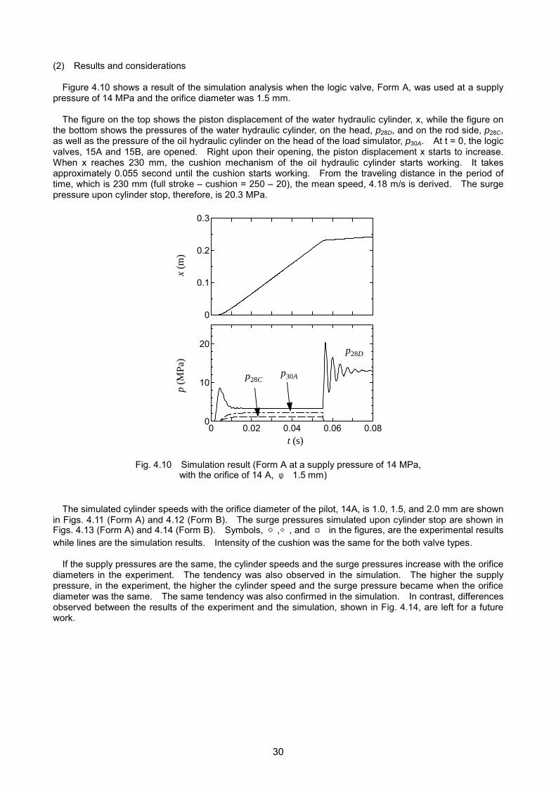
3.2.2 Test result The test system was operated at a constant water temperature of 30 to 32 ℃ with a load of 14 MPa for 30 seconds and then with almost no load (1.5 MPa) for 30 seconds, as shown in Fig. 3.3. The test was continued for approximately eight hours a day during the test period of 259 days (total operating time: 1,592 hours). Figure 3.4 shows the test results.
5
6
7
8
9
0 400 800 1200 1600
運転時間(h)
pH値
タンク
フィルタ
Acc.
0
10000
20000
30000
40000
50000
60000
0 400 800 1200 1600
運転時間(h)
一般
細菌
(個/m
L)
Gen
eral
bac
teria
(cel
l/mL)
タンク
フィルタ
Tank Filter Acc.
0
40
80
120
160
200
0 400 800 1200 1600
Operating time (h)
運転時間(h)
塩素
イオ
ン(m
g/L)
タンク
フィルタ
Acc.
0
50
100
150
200
250
300
0 400 800 1200 1600
運転時間(h)
硬度
(mg/
L)
タンク
フィルタ
Acc.
0
100
200
300
400
500
0 400 800 1200 1600
タンク
フィルタ
蒸発
残留
物(m
g/L)
Acc.
運転時間(h)
Tank Filter
Tank Filter
Operating time (h) Operating time (h)
Evap
orat
ion
resi
due
(mg/
L)
pH
Har
dnes
s (m
g/L)
Clo
rine
ion
(mg/
L)
Tank Filter Tank
Filter
Fig. 3.4 Water quality evaluation results
Operating time Operating time
19

As shown in Fig. 3.4, the levels of pH, chlorine ions, hardness, and evaporation residue remained considerably lower than those defined by the tap water standard. They showed no major variations or differences among the monitoring points. According to the sets of sampling data, excluding the forth one, the bacteria count increased in the initial phase (120 hours from the test start to the 15th day) and then decreased due to starvation and death, regardless of the sampling points. The same test was conducted at a constant water temperature of 40 to 42 ℃ for 110 days (total operating time: 670 hours,) and similar results were obtained. The system water was sampled at the 15th day, which confirmed a growth of general bacteria. To check the bacteria growth rate in the initial phase, the system was intermittently operated, similarly as shown in Fig. 3.3, at a constant water temperature of 40 ℃ around-the-clock for 20 days. Figure 3.5 shows the bacteria count in the water sampled daily. For reference, the bacteria count in a stopped water hydraulic system is also indicated, the water temperature in which was kept at 40 ℃. The figure shows that the bacteria growth was rapid in the initial phase in both cases. The growth in the running system takes place in an earlier stage than in the reference case. This phenomenon is supposedly associated with the points where the water was sampled. It was sampled from the tank bottom; it is assumed that the spread of bacteria in the tank took more time in the stopped system. The bacteria growth in the stopped system had a higher peak than that in the running system.
0
5000
10000
15000
20000
25000
30000
35000
1 2 3 4 5 6 7 8 9 10 11 12 13 14 15 16 17 18 19 20
Day
Gen
eral
bac
teria
(Cou
nt/m
L)G
ener
al b
acte
ria (c
ell/m
L)
StoppedOperating
Fig. 3.5 Bacteria count in the initial test phase Influence of the ambient room temperature and the filter mesh size in the air breather for the bacteria growth was examined and Fig. 3.6 shows the test results. Using a 40-µm-mesh filter, Tests 1 and 2 were carried out in a cold season (February 26 to March 17 in 2002) and in a hot season (August 12 to September 4 in 2003), respectively. Test 3 was conducted from October 27 to November 18 in 2003, using a 1-µm mesh filter. In all the tests, the system was operated at a constant water temperature of 40 ℃. As shown in the figure, the bacteria count started to rise just after the test start and reached at the maximum level in a day or two. Then, the count declined to below 4,000 cells/mL in ten days and remained at almost the same level. The bacteria growth in Test 3 had a peak lower than that in Test 2 but a slightly higher than that in Test 1. Considering that Test 1 was conducted in the winter (room temp.: approx. 15 ℃) while Test 2 was in the summer (approx. 30 ℃), Figure 3.6 suggests that the room temperature is a more influential factor on the bacteria growth than the filter mesh size.
20

0
20000
40000
60000
80000
100000
120000
140000
160000
180000
200000
1 2 3 4 5 6 7 8 9 10 11 12 13 14 15 16 17 18 19 20 21 22 23
Day
Gen
eral
bac
teria
(Cou
nt/m
L) Experiment 1 (40µm, Room temp. 15℃)
Experiment 2 (40µm, Room temp. 30℃)
Experiment 3 (1µm, Room temp. 21℃)
Fig. 3.6 Influence of the room temperature and the mesh size of the air breather on bacteria growth
3.3 Guidelines for water quality control ADS uses tap water, which may be affected by algae and bacteria growth or pH variations, depending on
the service conditions. Table 3.1 describes how the water quality change in the system affects the system components. To prevent potential risks associated with those factors, the water quality control is required as outlined in Table 3.2.
Table 3.1 Influence of water quality change on system components
Factor Potential influence on the components
Bacteria and algae growth
- Solenoid-operated directional valve/relief valve: spool malfunction - Strainer: clogged filter element - Cylinder: deteriorated sealing performance - Pump/motor: clogged drain path in the casing
Chlorine ions Causes crack on stainless steel with stress corrosion. Water pH A low water pH opts to corrode metals more severely.
Table 3.2 Control factor and reference value
Control element and description Reference value 1)
pH A lower pH value may result in corrosion. 6.5 to 8.5
Chlorine ions A higher chlorine level causes corrosion of stainless steel (crevice corrosion). 200 mg/L or less
Hardness Higher hardness increases a risk of calcium deposition, which results in corrosion. 300 mg/L or less
Evaporation residue
The residue mainly contains salt and organic constituents such as calcium, magnesium, and silicate, which cause metal corrosion in the piping.
500 mg/L or less
General bacteria
Counts of both bacteria and other microorganisms per 1 ml of water. Used as a measure of water contamination. 100 cells/mL or less
1) The values for pH and chlorine ions are based on Nessie standards of Danfoss K. K.; those for hardness, evaporation residue, and general bacteria are on the water quality standard defined by the Ordinance No. 69 of Ministry of Health and Welfare in Japan.
21

Maintenance method: It is preferable to have a filtering system that removes bacteria and other microorganisms from the working water. Figure 3.7 describes removal of contaminants of different sizes in the water.
Size C
onta
min
ant Germs Microorganisms Viruses Organic
Dirt Silica colloid
Inorganic Rust
Electronic microscope Visual Observation method
Optical microscope
Filter Microfilter Removal method Hollow fiber
Fig. 3.7 Removal of contaminants of different sizes
Sources) Shoji Kubota, “Atarashii mizuno kisochishiki” (in Japanese, the title translated as “Basics of new water”), Ohmsha Ltd. (ISBN: 4-274-11989-0) Shoji Kubota and Ichiko Nohara, “Jousui, seisui, kassui no kisochishiki” (in Japanese, the title translated as “Basics of purified, treated and activated waters”), Ohmsha Ltd. (ISBN: 4-274-02303-6)
22

Chapter 4 Operating Aqua Drive System
4.1 High-speed operation To clarify problems and establish guidelines for putting an aqua drive system into practical applications, an experiment was conducted to simulate injection and dwelling processes of the conventional oil hydraulic precision molding machine with ADS. A target speed of a water hydraulic cylinder used in the model was set to 4 m/s, which is equivalent to a general cylinder speed for oil hydraulic precision molding machines that run in a middle pressure range. Use of tap water as the system fluid could make the cylinder exceed the target speed while it could reveal various problems unique to ADS. The experiment focused on verifying rapidity of the water hydraulic cylinder and pressure behavior on the water hydraulic components when model is run in a circuit, consisting of an accumulator as an auxiliary water pressure source and logic valves.
4.1.1 Experimental apparatus and method Figures 4.1 and 4.2 show a circuit diagram of the experimental apparatus and the apparatus images, respectively. The apparatus consists of a water hydraulic unit, a water hydraulic cylinder, and a load simulator unit. In the aqua drive unit, a fixed capacity pump of 30 cm3/rev is driven by a 15-kW inverter motor to supply water at 43.5 L/min (when running at 1,450 min-1). The rated pressure of the circuit was 14 MPa. On the pump discharge side, a high-speed operation circuit is connected, which comprises of high-capacity logic valves and an accumulator. The water hydraulic cylinder was used for performing the injection and dwelling processes. The solenoid valve circuit was used for retracting the cylinder. The water hydraulic cylinder, designed as an injection cylinder (cylinder inner diameter: 40mm, rod diameter: 22 mm, and stroke: 250 mm), was connected to that in the same size of the oil hydraulic cylinder, which simulates the load. The load simulator, consisting of an oil hydraulic cylinder and oil hydraulic unload valve, controls loading and unloading to simulate loads of the precision molding machine.
V
alve unit Cylinder displacement xWhc
Aqua driv
Water hydraulic pump unit
Inverter
Fig 4.1 Circuit diagram of the experimental apparatus
23
Load simulator
ater ydraulic ylinder
e unit

(a) Overview (b) Load simulator (Water hydraulic and oil hydraulic cylinders)
(c) Valve unit (Logic valve and accumulator)
(b) Dummy load (Unloading relief valve)
Fig. 4.2 Appearances of the experimental apparatus
Experimental parameters and measurement items are as follows. (1) Experimental parameters (See Fig. 4.1)
・ Discharge pressure of Pump 3: Set it with Relief valve 10 as an accumulated pressure of Accumulator 13.
・ Loading pressure of loading cylinder 29: Set it with Relief valve 31. ・ Pilot flow rate of Logic valve 15: Set it by replacing a Fixed-orifice 14 of Pilot valve 12.
(2) Measurement items (See Fig. 4.1)
・ Pressures Pump discharge pressure: P8A Pressures of the injection cylinder rod side and the head side: P28C and P28D Pilot pressure of the logic valve: P14A and P14B Pressure of the loading relief valve: P30A
・ Cylinder displacement: x
24

Three processes described in Fig. 4.3 are defined as one operation cycle.
Dwelling Injection Retract C
ylin
der d
ispl
acem
ent The cylinder is retracted
by closing the logic valve and switching the direction switch valve.
Loading pressure of 3 MPa or higher is held for 0.5 sec.
The unloading valve is switched to the state of loading.
e Fig. 4.3 Operation pattern
4.1.2 Experimental results (1) Experimental conditions
Experimental conditions are as follows. ・ Pump flow: 22.5 L/min ・ Supply pressure: 12MPa, 13MPa, 14MPa ・ Accumulator pressure: 70 % of the supply pressure ・ Relief pressure in the load simulator: 15.5 MPa ・ Orifice diameter of the pilot in the logic valve: 1.0 mm, 1.5 mm, 2.0mm
2
2.5
3
3.5
4
4.5
11.5 12 12.5 13 13.5 14
シリ
ンダ
速度
m/s
Cyl
inde
r spe
ed
m/s
供給圧力 MPaSupply pressure MPa 絞り直径φ1.0mm 絞り直径φ1.5mm 絞り直径φ2.0mm●: Orifice dia. φ 1.0 mm, ▲: Orifice dia. φ 1.5 mm, ■: Orifice
Fig. 4.4 Cylinder speed vs. supply pressure changed
with orifice diameter of the pilot in the logic
25
Tim
14.5
dia. φ 2.0 mm
valve

(2) Result A Figure 4.4 shows the effect of supply pressure and the orifice diameter of the pilot in the logic valve. The figure shows that the operational speed increases with the orifice diameter. When the orifice diameter is 2.0 mm and the supply pressure is 14 MPa in particular, the cylinder moves 4.14 m/s, which exceeds the target value. The cylinder speed, however, saturates when the orifice diameter is 1.5 mm or larger. The result indicates that combination of the accumulator and the logic valves is effective to accelerate the cylinder movement in ADS. Figure 4.5-1 shows changes of the cylinder displacement and pressures at each measured point in the system when the supply pressure is at 14 MPa and the orifice diameter is 1.5 mm. Figure 4.5-2 shows details of the results, focusing the injection and dwelling processes. The water hydraulic cylinder speed drastically drops at the cylinder end in Fig. 4.5-2 due to the cushion effect of the oil hydraulic cylinder. This result suggests that, to simulate loads of the precision molding machine more precisely, loads must be applied with an unloading valve of high response just before the cylinder end. Note that the pressure rise on the cylinder head and rod sides immediately after the cylinder movement can be suppressed by opening the rod-side logic valve earlier than the cylinder movement.
0
50
100
150
200
250
0 0.5 1 1.5 2 2.5
-2
0
2
4
6
8
10
12
14
16
18
20
時間 s
シリ
ンダ
変位
mm
Cyl
inde
r dis
plac
emen
t m
m
圧力
MP
aPr
essu
re
MPa
x
P30A
P8A
P28D
P28C
P14A
P14B
Time s
Fig. 4.5-1 Cylinder displacement and pressure vs. time (Supply pressure: 14 MPa. Orifice diameter: 1.5 mm)
0
50
100
150
200
250
0.25 0.3 0.35 0.4 0.45 0.5 0.55
時間 s
シリ
ンダ
変位
mm
Cyl
inde
r dis
plac
emen
t m
m
-2
0
2
4
6
8
10
12
14
16
18
20
圧力
MP
aPr
essu
re
MPa
x
P30A
P8A
P28D
P28C
P14A
P14B
Time s
Fig. 4.5-2 Cylinder displacement and pressure vs. time (Supply pressure: 14 MPa. Orifice diameter: 1.5 mm.
Magnified: the time from 0.25 to 0.55 seconds)
26

(3) Pressure rise estimation The surge pressure upon cylinder stop in ADS is generally higher than that in oil hydraulic systems due to low compressibility of water. The surge pressure, which is one of serious issues for the ADS applications, depends on the cylinder speed; thus, it should be estimated as a guideline for designing piping. When the supply pressure is , the water density is , and the maximum cylinder speed of the injection process is , a theoretical maximum surge pressure is given by the following equation:
p ρ ν
maxp
, maxp p aρ= + v where is the velocity of pressure wave and is defined as a ρ/Ka = with as the bulk module of the water.
K
Figure 4.6 shows comparisons of the maximum surge pressures: those theoretically calculated using the equation above and those measured in the experiment by stopping the cylinder running at a high speed. The data shows that the all theoretically obtained surge pressures are higher than those measured in the experiment. If the system designer can know the maximum speed of the cylinder in the design phase, the maximum surge pressure in the real system can be estimated. Note that the measured surge pressures were lower than the estimated because the cylinder decelerated in the cushion mechanism before it stopped.
12
14
16
18
20
22
12 12.5 13 13.5 14
シリ
ンダ
停止
時ヘ
ッド
側サ
ージ
圧力
MP
a
Surg
e pr
essu
re u
pon
cylin
der s
top
on
the
head
sid
e M
Pa
理論値(φ1.0)Theoretical (φ1.0)
理論値(φ1.5)Theoretical (φ1.5)
理論値(φ2.0)Theoretical (φ2.0)
実験値(φ1.0)Experimental (φ1.0)
実験値(φ1.5)Experimental (φ1.5)
実験値(φ2.0)Experimental (φ2.0)
S
Fig. 4.6
(4) Result B To explore possibility for rapitypes of logic valves; geometriewater hydraulic logic valve usedTo identify the valves, the valvecalled Form B. These valves have a differentare different. Form B has a highigh-speed cylinder operation. Figure 4.8 shows a compariscylinder speed of Form B exceecylinder stop was also increased
供給圧力 MPaupply pressure MPa
Comparison of the theoretical surge pressures maxpand the experimental surge pressures
d cylinder speed, changes in the cylinder speed were measured using two s of the main valves are different to each other. Figure 4.7 indicates the in the experiment, showing the circuit diagram of the valve unit in Fig. 4.1.
described in Fig. 4.1 is called Form A while the one described in Fig. 4.7 is
geometry of the logic main valve; the valve opening-flow rate characteristics her tolerance to the opening-flow rate changes; it was expected to achieve
on of the two valves at high-speed operation. The result indicates that the ds the performance of Form A overall. In addition, the surge pressure upon .
27

Fig. 4.
2.0
2.5
3.0
3.5
4.0
4.5
5.0
1
シリ
ンダ
速度
m/s
Cyl
inde
r spe
ed
m/s
12
13
14
15
16
17
18
19
20
21
1
サー
ジ圧
力 M
Pa
Surg
e pr
essu
re
MPa
(5) Conclusions
1. Combination of high-chigher. The speed imachines that run in a
2. The surge pressure estimated.
Valve unit
7 Circuit diagram of a water hydraulic logic valve, Form B
2 13 14
供給圧力 MPa
Form A, φ1.0
Form A, φ1.5
Form A, φ2.0
Form B, φ1.0
Form B, φ1.5
Form B, φ2.0
Supply pressure MPa
2 13 14
供給圧力 MPa
Form A, φ1.0
Form A, φ1.5
Form A, φ2.0
Form B, φ1.0
Form B, φ1.5
Form B, φ2.0
Supply pressure MPa
Fig. 4.8 Cylinder speed and the surge pressure of the valves Form A and B
apacity logic valves and an accumulator achieved the cylinder speed of 4 m/s or s equivalent to normal cylinder speed in the oil hydraulic precision molding middle pressure range. upon stop of the operating water hydraulic cylinder (cushion area) can be
28

4.1.3 Simulation (1) Simulation model A simulation analysis was conducted to investigate a relation among the orifice diameter of the pilot in the logic valve, 14a, the cylinder speed, and the surge pressure. Figure 4.9 shows a diagram of the circuit to be analyzed. The simulation was conducted by deriving basic equations of the main components configuring the circuit. Considerations for deriving the basic equations of the main components were as follows.
・ Constant flow rate of the pump ・ Override characteristics of the relief valve ・ Polytrophic change of the gas in the accumulator ・ Compressibility of the fluid in the cylinder chambers and changes of the cylinder chamber
volumes ・ Equations for cylinder motion including inertia, viscosity, and friction force ・ Dynamic of piping ・ Assumption that the cushion force is proportional to the cylinder speed ・ Override characteristics when the relief valve is open. ・ The flow rate passing through the relief valve, thinking the relief valve as the orifice when closed. ・ Equation of the poppet motion and flow rate characteristics, as well as water compressibility ・ Effect of the orifice of the pilot, 14A
M
15
B
15
A
28 29
31
32
P
30A
P
28C
P
28D
13
PH
PH
PH
シ
ロジック弁Logic valve
ロジック弁Logic valve
14
A絞りOrifice
リCdisp
Fig. 4.9 Circuit diag
ンダ変位 xylinder lacement x
33
ram for the simulation analysis
29
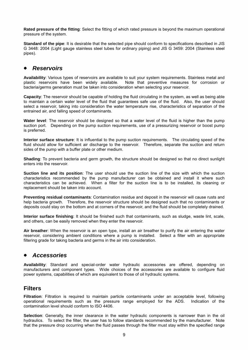
(2) Results and considerations Figure 4.10 shows a result of the simulation analysis when the logic valve, Form A, was used at a supply pressure of 14 MPa and the orifice diameter was 1.5 mm. The figure on the top shows the piston displacement of the water hydraulic cylinder, x, while the figure on the bottom shows the pressures of the water hydraulic cylinder, on the head, p28D, and on the rod side, p28C, as well as the pressure of the oil hydraulic cylinder on the head of the load simulator, p30A. At t = 0, the logic valves, 15A and 15B, are opened. Right upon their opening, the piston displacement x starts to increase. When x reaches 230 mm, the cushion mechanism of the oil hydraulic cylinder starts working. It takes approximately 0.055 second until the cushion starts working. From the traveling distance in the period of time, which is 230 mm (full stroke – cushion = 250 – 20), the mean speed, 4.18 m/s is derived. The surge pressure upon cylinder stop, therefore, is 20.3 MPa.
0
0.1
0.2
0.3
0 0.02 0.04 0.06 0.080
10
20
t (s)
x (m
)p
(MPa
)
p28D
p28Cp30A
Fig. 4.10 Simulation result (Form A at a supply pressure of 14 MPa, with the orifice of 14 A, φ 1.5 mm) The simulated cylinder speeds with the orifice diameter of the pilot, 14A, is 1.0, 1.5, and 2.0 mm are shown in Figs. 4.11 (Form A) and 4.12 (Form B). The surge pressures simulated upon cylinder stop are shown in Figs. 4.13 (Form A) and 4.14 (Form B). Symbols, ○,◇, and □ in the figures, are the experimental results while lines are the simulation results. Intensity of the cushion was the same for the both valve types. If the supply pressures are the same, the cylinder speeds and the surge pressures increase with the orifice diameters in the experiment. The tendency was also observed in the simulation. The higher the supply pressure, in the experiment, the higher the cylinder speed and the surge pressure became when the orifice diameter was the same. The same tendency was also confirmed in the simulation. In contrast, differences observed between the results of the experiment and the simulation, shown in Fig. 4.14, are left for a future work.
30

12 13 142
3
4
5
6
○ 2.0◇ 1.5□ 1.0
12 13 142
3
4
5
6
○ 2.0◇ 1.5□ 1.0
絞り 14A (Form A) (mm)
供給圧力 (MPa)
シリンダ速度
(m/s
)C
ylin
der s
peed
m
/s
絞り 14A (Form B) (mm)
供給圧力 (MPa)
シリンダ速度
(m/s
)C
ylin
der s
peed
m
/s
Orifice 14A (Form A) (mm) Orifice 14A (Form B) (mm)
Supply pressure MPa Supply pressure MPa
Fig. 4.11 Mean cylinder speed (Form A) Fig. 4.12 Mean cylinder speed (Form B)
12 13 1410
15
20
25
○ 2.0◇ 1.5□ 1.0
12 13 1410
15
20
25
○ 2.0◇ 1.5□ 1.0
絞り 14A (Form A) (mm)
供給圧力 (MPa)
サージ圧
(MPa
)Su
rge
pres
sure
M
Pa
絞り 14A (FromB) (mm)
供給圧力 (MPa)
サージ圧
(M
Pa)
Surg
e pr
essu
re
MPa
Orifice 14A (Form A) (mm) Orifice 14A (Form B) (mm)
Supply pressure MPa Supply pressure MPa Fig. 4.13 Surge pressure upon cylinder stop Fig. 4.14 Surge pressure upon cylinder stop (Form A) (Form B)
31

4.2 ADS operational guideline
4.2.1 Pressure loss and flow rate Water is a fluid of low viscosity, and its pressure loss in lines is much less compared to that of oil. Therefore, the following can be some of the advantages that water can provide as a fluid.
Inner diameter of fluid lines can be smaller. Energy loss is minimized even when the actuator and pump should be installed distant to each other.
V
p +Δp pd
LV
p +Δp pd
L
Fig. 4.15 Pipe
Water pressure loss and oil pressure loss, measured for water and oil flows in a pipe of the same size at
the same flow rate, are compared. When a fluid of density ρ, kinematic viscosity ν, and flow velocity V is flown in a pipe, inner diameter and length of which are d and L, respectively, the pressure loss Δp can be expressed by the following equation.
Δр=dL
2λρ
V2
λ is the pipe friction coefficient and can be expressed as follows, assuming that the Reynolds number Re is equal to Vd/ν.
λ=Re64
(laminar flow) and λ=4 Re3164.0
(turbulent flow), respectively.
Assuming that flow in the water hydraulic pipe is turbulent while that in the oil hydraulic pipe is laminar, the ratio of the respective pressure loss can be expressed by the equation below. In the equation, a subscript w means water hydraulics whereas a subscript o means oil hydraulics.
o
w
ρρ
∆∆
=oo
ww
ρλρλ
=6.464/3
⎟⎠⎞
⎜⎝⎛
dQ
(Eq. 4.1)
Assuming that the flows in the water and oil hydraulic pipes are both turbulent, the ratio can be expressed by the equation below.
o
w
ρρ
∆∆
=oo
ww
ρλρλ
=0.474 (Eq. 4.2)
Pressure losses, Δρw in a water hydraulic line and Δρo in an oil hydraulic line, are both calculated using values listed in Table 4.1 and are plotted in Fig. 4.16.
Table 4.1 Values used for the pressure loss calculation
Water Oil ρ (㎏/m3) 1,000 880 ν (m2/s) 1.0 x 10⁻⁶ 34.0 x 10⁻⁶
32

The y-axis indicates the ratio Δρw/Δρo while
the x-axis indicates flow rate Q. The pipe size d is taken as its parameter. The ratio was calculated using a Schedule 80 line, from 1/8 to 21/2 of the nominal diameter. Calculations obtained by Eq. 4.1 were indicated with solid lines while those obtained by Eq. 4.2 were indicated with a broken line. In every case, the ratio remains smaller than 1. From this result, the pressure loss in a water hydraulic line is smaller than that in an oil hydraulic line. Due to low kinematic viscosity of water, the pressure loss in a water hydraulic pipeline is small, and thus advantageous as a power transmitting line. Application of water hydraulics to a drive system where the pump and the control valve or the actuator are separately installed and a compact system of which pipelines are of small diameter is suitable.
TurbulentPipe: Schedule 80
Flow rate L/min
Pres
sure
loss
ratio
(W
ater
hyd
raul
ics/
oil h
ydra
ulic
s)
Fig. 4.16 Comparison of pressure loss in water hydraulic line and in oil hydraulic line
4.2.2 Surge pressure prevention (1) Surge pressure Generation of surge pressure must be paid attention to when flow rate of a fluid power system is high while sudden run and stop of the system are demanded. In the ADS, the surge pressure becomes higher compared to that of the oil hydraulic system due to properties of water. Therefore, if the user's ADS is expected to run for fast action while generation of excessive surge pressure is anticipated, excogitating the water hydraulic circuit and devices configuring the system n the designing stage is desirable. For example, realizing a shock-less drive using some controllable devices, such as a proportional valve and a servo valve, can be considered. ����������
����������������������������������������
��������������������
V V-⊿V
⊿p
-⊿p
��������������������������������������������������
��������������������
V V-⊿V
⊿p
-⊿p
(2) Surge pressure test and simulation analysis in a cylinder drive circuit
Using a cylinder drive circuit described in Fig. 4.18, an experiment was conducted to examine the surge pressure that occurs upon a sudden shutting of a valve. The flow velocity was 9.05 m/s. The servo valve was closed, following the pattern described in Fig. 4.19. The surge pressure was measured from the transient pressure wave of the port B.
p∆
Fig. 4.17 Surge pressure generation due to shutting a valve Figure 4.20 shows the test and simulation results. The
figure indicates the simulation sufficiently reproduced the test results. (3) Surge pressure prevention method The experiment and simulation provide the following findings: ① Extending the valve manipulation time of the servo valve suppresses the surge pressure; ② Adapting two-slope manipulation effectively suppresses the surge pressure, and adjusting the time of
slopes and applied voltages (valve-opening) can minimize the surge pressure generation.
33

p2
p1
7 MPa
M
管路:5m 1/8’
印加電圧 u
変位 y
負荷:50 kg 受圧面積 Ac
A B
P T
管路:1m 1/8’
p3
p4
W1 W4
q1 q4
0 t (s)
u (V)
T
9 (V)
1 (V)
T/2
(3/4)T
A B
C
Pattern パターン
Pressure-receiving area Load: 50 kg
Displacement
Pattern Pipe: 1 m 1/8’ Pipe: 5 m 1/8’
tT
u
Applied voltage
Fig. 4.18 Surge pressure test apparatus Fig. 4.19 Two-slope manipulation
–0.050
2
4
6
8
p 2 (M
Pa)
計算結果
∆p
シミュレーション結果 Simulation E
Fig. 4.20 Comparison of theusing the ser
4.2.3 System configuration and o(1) Filtration
・ Water supply filter: The water supply filterupon water supply for maintaining the systto the system. When the water is suppsystem shall be sufficiently drained to re-entering to the system.
・ Filtration equipment (filter): To eliminate microorganic substances, the filtration eqsupply line, the return line, the suction ldesigned so that it enables to monitor the
・ Air breather: Bacteria in the air should be tfilters (1 micron or less) can be used.
・ Monitoring of the filter pressure loss: Propwater hydraulic components, but also is imsystem. Therefore, the system is desirablyis allowed.
実験結果xperiment
0 0.05 0.1t (s)
experimental and simulation results vo valve (Pattern A)
perational considerations
should be equipped, at the initial stage of operation and em water level, to prevent foreign materials from migrating lied to a system, which is not frequently operated, the prevent water from containing rust and the rust from
substances causing contamination, bacteria, and other uipment shall be equipped with lines such as the water ine, and so forth, if necessary. The system is desirably clogging of such filters. aken into account for filter grade selection. Hollow-paper
er filtration of the fluid not only extends the lifetime of the portant to demonstrate the maximum performance of the
designed so that the monitoring of the filter pressure loss
34
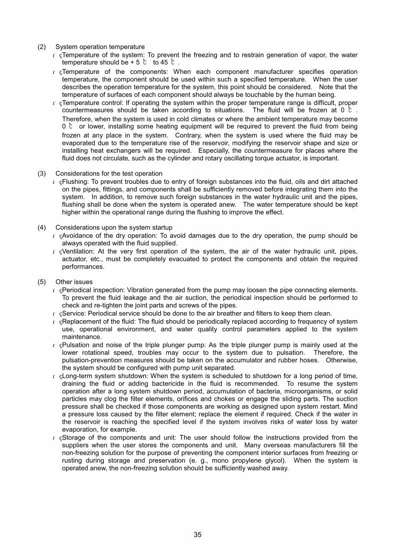
(2) System operation temperature ・ Temperature of the system: To prevent the freezing and to restrain generation of vapor, the water
temperature should be + 5 ℃ to 45 ℃. ・ Temperature of the components: When each component manufacturer specifies operation
temperature, the component should be used within such a specified temperature. When the user describes the operation temperature for the system, this point should be considered. Note that the temperature of surfaces of each component should always be touchable by the human being.
・ Temperature control: If operating the system within the proper temperature range is difficult, proper countermeasures should be taken according to situations. The fluid will be frozen at 0 ℃ . Therefore, when the system is used in cold climates or where the ambient temperature may become 0 ℃ or lower, installing some heating equipment will be required to prevent the fluid from being frozen at any place in the system. Contrary, when the system is used where the fluid may be evaporated due to the temperature rise of the reservoir, modifying the reservoir shape and size or installing heat exchangers will be required. Especially, the countermeasure for places where the fluid does not circulate, such as the cylinder and rotary oscillating torque actuator, is important.
(3) Considerations for the test operation
・ Flushing: To prevent troubles due to entry of foreign substances into the fluid, oils and dirt attached on the pipes, fittings, and components shall be sufficiently removed before integrating them into the system. In addition, to remove such foreign substances in the water hydraulic unit and the pipes, flushing shall be done when the system is operated anew. The water temperature should be kept higher within the operational range during the flushing to improve the effect.
(4) Considerations upon the system startup
・ Avoidance of the dry operation: To avoid damages due to the dry operation, the pump should be always operated with the fluid supplied.
・ Ventilation: At the very first operation of the system, the air of the water hydraulic unit, pipes, actuator, etc., must be completely evacuated to protect the components and obtain the required performances.
(5) Other issues
・ Periodical inspection: Vibration generated from the pump may loosen the pipe connecting elements. To prevent the fluid leakage and the air suction, the periodical inspection should be performed to check and re-tighten the joint parts and screws of the pipes.
・ Service: Periodical service should be done to the air breather and filters to keep them clean. ・ Replacement of the fluid: The fluid should be periodically replaced according to frequency of system
use, operational environment, and water quality control parameters applied to the system maintenance.
・ Pulsation and noise of the triple plunger pump: As the triple plunger pump is mainly used at the lower rotational speed, troubles may occur to the system due to pulsation. Therefore, the pulsation-prevention measures should be taken on the accumulator and rubber hoses. Otherwise, the system should be configured with pump unit separated.
・ Long-term system shutdown: When the system is scheduled to shutdown for a long period of time, draining the fluid or adding bactericide in the fluid is recommended. To resume the system operation after a long system shutdown period, accumulation of bacteria, microorganisms, or solid particles may clog the filter elements, orifices and chokes or engage the sliding parts. The suction pressure shall be checked if those components are working as designed upon system restart. Mind a pressure loss caused by the filter element; replace the element if required. Check if the water in the reservoir is reaching the specified level if the system involves risks of water loss by water evaporation, for example.
・ Storage of the components and unit: The user should follow the instructions provided from the suppliers when the user stores the components and unit. Many overseas manufacturers fill the non-freezing solution for the purpose of preventing the component interior surfaces from freezing or rusting during storage and preservation (e. g., mono propylene glycol). When the system is operated anew, the non-freezing solution should be sufficiently washed away.
35

Chapter 5 Application of Aqua Drive System
5.1 Applicable fields of ADS ADS has been increasingly adopted to food processing machines, medical and care tools, and nuclear power plant facilities. Figure 5.1 shows the result of a survey conducted with questionnaire on applicable fields of ADS for the water hydraulic component suppliers listed in Section 2.1. The questionnaire listed 9 fields Water Hydraulics Committee and JFPA see them as immediate potentials for ADS and 10 additional fields and asked the suppliers if they have adapted or will adapt ADS for those fields. Almost 80% of the 50 responses suggested possible ADS applications. The survey reveals 123 cases of ADS applications, as shown in Fig. 5.1, approximately 50% of which are in the fields of (1) food processing, (2) maritime and offshore, (3) civil engineering, and (4) medical and care (descending ranking). The rest includes the fields of (5) nuclear, (6) underwater, (7) home appliances, (8) leisure, and (9) medicine. "Other fields" include applications in the following fields.
(1) General industrial machinery: 7 cases (machines, industrial machines, tire forming machines, injection molding machine, clamp equipment)
(2) Cleaning: 5 (cleaning, fire fighting, high-pressure jet/spray, high-pressure water hydraulic unit) (3) General industrial equipment: 4 (manufacturing line/plant, factory automation, steel making, vehicle
production) (4) Semiconductor: 4 (semiconductor manufacturing equipment, molding machine, electronics) (5) Others: 3 (coolant line for machine tools, pool, research)
23
5
5
9
9
10
14
15
16
17
0 5 10 15 20 25
Other fields
Medicine
Leisure
Home appliances
River
Nuclear
Medical and care
Civil engineering
Vessels and offshore
Food processing
Fig. 5.1 Applications of the ADS technology
The machines and equipment specifically cited are as follows.
(1) Food processing: Food processing machine (2) Medical and care: Lifter, bathing assistance equipment, dental instrument (3) Leisure: Pool bed lifter (4) River: Drive system for fish gates, high-pressure cleaner (5) Civil engineering: Pile driver, water hydraulic trench (6) Vessels and offshore: Local application fire fighting systems for the machine room (7) Nuclear: Cooling water circulator, waste treatment system (8) Others and general industry: Hydroforming machine
In addition, the ADS technology can potentially be applied to the following:
Seawater desalination unit, paper-manufacturing machine, home elevator, shield machine, disk molding machine, underwater development machinery, movable theatrical stage, amusement equipment, packing machine, and rescue tool.
36

Water hydraulic systems are generally appreciated in fields that demand safety, environmental friendliness, cleanliness, low-pressure range, low related costs, high power density, and applicability in outdoor/water front sites. According to the survey, the companies have applied the ADS technology mainly because of lower environmental impact, as described below.
(1) Environment (nature preservation): 8 cases (2) Safety and cleanliness: 4 (3) Availability of the fluid/pressure source (tap water): 2 (4) No contamination upon leakage of the fluid: 2 (5) No wastewater treatment required: 1 (6) Not sensitive to radioactivity: 1
5.2 Published ADS applications Table 5.1 lists ADS applications published in the Japanese journals and newspapers before the year 2002. The organizations include companies, university laboratories, and research committees formed by companies. Some of the applications below are still under study. Table 5.2 presents the some of their images and specifications.
Table 5.1 Publications on the ADS applications
No. Organization Source (date) Application field and feature
1 Lift
- KAYABA INDUSTRY CO., LTD.
HYDRULICS AND PNEUMATICS, Vol. 39, No. 13, (2000.11)
Welfare equipment - Driven by tap water pressure
2 Automatic poultry breast deboner
- MAEKAWA SEISAKUJO CO., LTD
Nikkan Kogyo Shimbun, Ltd. (2001.2.16), others
Primary food processing - Can be cleaned with water, free from
electrical leakage, HACCP-conformed
3
Forklift - MITSUBISHI HEAVY
INDUSTRIES, LTD.
JOURNAL OF THE JAPAN FLUID POWER SYSTEM SOCIETY, Vol. 32, No. 2, (2001.3)
Industrial transporting vehicle (battery forklift) - Used where oil pollution must not occur.
4
Semiconductor forming press - New Energy and Industrial
Technology Development Organization
Report on Proposal Invitation Project of New Business Creation for the year of 2000 (2001.3.27)
Semiconductor molding - Ensuring uniform pressure distribution on
chips
5 Lift
- SANMAX CORPORATION JAPAN INDUSTRIAL JOURNAL, (2001.6.14), others
Lift unit - Clean & useful for disaster recovery.
Working pressure Max.: 1 MPa or less
6 Door slider
- NIPPON VALQUA INDUSTRY, LTD
FLUID POWER, Vol. 15, No. 3 (2001.7)
Automatic sliding door - Operated only with tap water pressure, quiet,
energy-effective, safe
7 Bathing assistance equipment
- NIPPON VALQUA INDUSTRY, LTD
FLUID POWER, Vol. 15, No. 3 (2001.7)
Bathing assistance lifter - Operated with tap water pressure,
height-adjustable
8
Water hydraulic drive system for sluice gates
- Study Committee for Sluice Engineering and Ecosystem
“Water Hydraulic Drive System for Sluice Gate” (2001.8)
Drive system for sluice gates - Environmentally friendly, powerful, safe
9 Motor (tap water use)
- TOKYO INSTITUTE OF TECHNOLOGY
Nikkei Sangyo Shimbun/Nihon Keizai Shimbun, Inc., (2001.10.29)
Care equipment - No electricity required, driven by tap water
pressure
10 Bathing assisting equipment
- LINE INDUSTRY CO., LTD. Nikkei Sangyo Shimbun/Nihon Keizai Shimbun, Inc. (2001.11.08)
Care/welfare equipment - Driven by water supply and discharge
pressures
11 Power cylinder
- FALCOM INC. Nikkan Kogyo Shimbun, Ltd. (2002.2.08)
Power cylinder driven by a servo motor - Converted from oil to water hydraulics for
environmental concerns
12
Semiconductor forming press - TOWA KIKI, CO., LTD.
Nikkei Sangyo Shimbun/Nihon Keizai Shimbun, Inc. (2002.12.03), others
Semiconductor packaging equipment - Environmentally friendly
37

Table 5. 2 ADS application
Applications using tap water pressure No. Name and image Specifications (circuit)
1
Lift
Source: KAYABA INDUSTRY CO., LTD. [No. 1 in Table 5.1]
Item Specifications
Drive source Tap water pressure (Min.: 0.2 MPa)
Allowable load 100 kg or less (body weight) Length Max.: 3.0 m/min.: 1.7 m
Lift stroke 1.3 m (For a pool, 1.1 to 1.3 m in depth)
Weight 32 kg in total (Cylinder body: 18 kg) Up-and-down switching
Switching with a manual valve (Up/down/stop)
Horizontal seat movement Moves manually.
Installation method Two types: plate and socket
リフタシステム
水道蛇口
水道用ホース
水圧源(上水道)
→排水口へ
2
Door slider
Source: NIPPON VALQUA INDUSTRY, LTD [No. 6 in Table 5.1]
Item Specifications
Drive source Tap water pressure (Min.: 0.2 MPa)
Working water pressure Max.: 0.3 MPa
Allowable door weight Max.: 20 kg
Max. door speed 250 mm/s
Cushioning 10 to 100 mm/s (closing side, adjustable)
Working force 58 N Working noise Max.: 40 dB Durability Min.: 0.2 million actions
Safety function The outer bracket is unlocked upon entanglement.
External power supply Not required
Working temperature
0 to 60 ℃ (no condensation)
Applicable in: Places where no electricity is allowed or special attention must be paid for safety (spa/bathroom, hospital, care facility, plant/research facility, and dangerous object (oil/organic solvent) warehouse)
Lifter system
Tap water outlet
Pressure source (Tap water pipe line)
To th
e dr
aina
ge
Tap water hose
Direction Control Valve
Rodless Cylinder
Limit Valve
38

Applications to factory machinery No. Name and image Specifications (circuit)
3
Automatic poultry breast deboner
Source: MAEKAWA SEISAKUJO CO., LTD [No. 2 in Table 5.1]
(Feature)
This machine consists of elevating stations on a revolving table and processing units and separates the upper body of poultry into breast, fillet, and bone. It can be frequently cleaned with water to ensure food safety and hygiene.
(Merits of ADS application) ・ Carefree for water cleaning (free from short circuits and
rust, HACCP-conformed) ・ Compact and high power, easily re-locatable ・ Facilitating food hygiene management ・ Allowing easy maintenance with a centralized drive
source
Item Specifications Throughput 900 pieces/hour Max.
ADS aspects Pressure Elevation unit: 7 MPa Processing unit: 2 MPa
Components Pump, motor, cylinder, servo valve, directional control valve, etc.
4
Semiconductor forming press unit
Source: New Energy and Industrial Technology Development Organization [No. 4 in Table 5.1]
(Feature) A press unit used to apply a resin coating to the outer surface of a wafer in a semiconductor manufacturing process
(Merits of ADS application) ・ Reducing environmental impact ・ Contributing to a more compact system (compact and
high power) ・ Permitting uniform resin coating with a direct pressure
from the water hydraulic cylinder ・ Allowing accurate position, speed, and pressure control
Item Specifications Pressing force 980kN Max.
Pressing speed Forming: 0.01 to 20 mm/s High-speed operation: 75 mm/s
Effective stroke 150mm
ADS aspect Pressure: 13.7 MPa Flow: 52 L/min
Components Pump, cylinder, servo valve, directional control valve, accumulator, etc.
39

Chapter 6 Future Perspectives of Aqua Drive System
6.1 Social demand and ADS Engineering, due to its nature and academic system, is fundamentally different from science. Science is to seek the absolute truth in any condition whereas engineering is to pursue optimal solutions with given conditions. In the 20th century, science and engineering developed the manufacturing industries and made an unprecedented achievement in both quality and quantity of production. However, just before the new millennium, when the mass production and consumption triggered problems, environmental destruction, or natural resource depletion, and when they obviously emerged, people have recognized the importance and urgency of taking actions to solve the problems and, gradually, they have started to reflect their behaviors as consumers. People start walking with a slogan, “the 21st century is the century of the environment,” and we can no longer neglect tangible and intangible factors from the industrial activities, or manufacturing products. In other words, the industrial activities have to change the course to be more human-friendly. Making the industrial activities more human-friendly is a requirement to education of engineers and technicians. This global paradigm shift will have an effect on the fundamental technologies in mechanical engineering. Drive systems having the variable-speed characteristics show excellent controllability to various types of motors and loads; they are essential for the manufacturing and working machinery in every manufacturing field. Now, the known drives are: oil hydraulics, pneumatics, and electricity. However, when it comes to compliance to the industrial conditions of the 21st century, there is no other drives but ADS using tap water as the fluid. ADS, by taking an advantage of tap water use, can assure our healthy environment: safety, cleanliness, and hygiene, and coexist with animals and plants as well as human beings. Anticipating such a global technological trend, universities, academic associations, or industrial organizations in Japan have been fostering a great interest in ADS and have worked out for long. The Japan Fluid Power Association has provided a ground for some important studies on water hydraulics and society: “Technical Study on Environmental Friendly Water Hydraulic Drive Systems (1998 to 2000)” and “Research and Study for the Practical Use of the Aqua Drive Technology (2001 to 2003).” This is the summary of the history of the primary research and studies done for the past six years. (1) The Committee organized and conducted experiments to investigate the water quality control issues and the water hydraulic driving characteristics. The experiments resulted in establishing a guideline for the water quality control. In the experiments, where a circuit modeling the injection and dwelling processes of an oil hydraulic precision molding machine, such as an injection molding machine or die cast machine, the high-speed operation using the logic valves was achieved. The Committee focused on the surge pressure generation in particular, and examined methods for the prediction and prevention. Their work established a guideline to actualize a practical water hydraulic application including the methods to design and control the system. (2) The Committee collected information to complete as a buyers’ guide that includes a list of manufacturers and suppliers covering specifications of their ADS components, responses of questionnaires regarding the materials, and some examples of the practical applications. The guide is designed to provide water hydraulics users with search courses to assist them. (3) The Committee published “Aqua Drive System – A Technical Guide.” This guide will contributes to promote the ADS widely to end users and system suppliers. This English version (the 2nd edition) will provide anyone interested in water hydraulic systems with the latest ADS information in Japan.
6.2 Market and prospects of ADS Some ADS applications were demonstrated in business expos.: a semiconductor sealing system in SEMICON Japan 2002 and an automated poultry breast deboner in FOOMA JAPAN 2003. They received attention especially from those who are environmentally aware in related industrial fields. However, they still have technical problems to overcome to actualize practical water hydraulic applications. To actualize the practical applications, it is important to select appropriate and potential fields and predict the market scale on the assumption that the water hydraulic products are adapted. The following 15 fields are suggested by our investigations as promising applicable fields of machinery and tools:
sluices/water gates for rivers, home elevators, injection molding machines, seawater desalination plants, atomic power plants, disk molding machines, semiconductor molding machines, food
40

41
processing machines, social welfare tools (lift, bed), shield machines, paper manufacturing machines, packing machines, movable theatrical stages and sports/amusement tools, rescue tools (deck guns), underwater development machinery.
To penetrate the ADS technology, solving technical problems and increase of recognition are essential. The following problems are picked up:
countermeasures to low temperatures, corrosion/erosion, sealing technology, reliability/lifetime, reduction of the initial cost, maintenance evaluation, water quality control, LCA evaluation.
Using the Delphi method, the Committee predicted when these problems become negligible for promoting ADS, or the time required to solve them. Experts including the Committee members concluded that it would be from three years to eight years, for which they can be responded with individual technologies and with some complicated technologies. The four driving systems: water hydraulics, oil hydraulics, pneumatics, and electricity, will be evaluated when ADS is more matured with metrics on environmental loads. The total market scale of water hydraulic products is estimated to become 60 billion-yen six years later, 2010, and 100 billion-yen in 2012. The Committee concludes that, appropriately sharing the market of the driving systems with the rest three methods and creating new applicable fields, the market output in 2012 will exceed 100 billion-yen.
6.3 Boosting the ADS-related industries The introduced ADS technologies are now start transforming into practical applications. Building up an organic linkage between academic, industrial, and government organizations is a must to facilitate the transformation. Some primary linkages are explained below. Linkage between water hydraulic component and ADS-applied system manufacturers and end users: An interactive link should be built between water hydraulic component/ADS-applied system manufacturers and end users. The end users will easily recognize ADS and have interests because the technology is characterized by some keywords describing essential elements to our daily life: environmental issues, safety, or cleanliness. Component manufacturers need to supply not individual components but systems to ADS-applied system manufacturers, satisfying demands of the end users. A tide from the both sides will surely build a virtuous circle involving the ADS-applied system manufacturers. Linkage between component and material manufacturers: To solve the technical problems and promote the commercial supply of ADS, this link should be important in addition to the component-manufacturers link. The operational pressure range of ADS is from the water pipe network pressure to 14 MPa. Because ADS operates in a wide operational pressure range from the tap water level to 14 MPa or higher, selecting appropriate materials and treatment/processing methods and developing appropriate system configuration are critical. Each manufacturer will be responsible for and collaborate together in the linkage for these issues. Linkage between young engineers and users: Communication with the engineers and the users through educational opportunities or promotion activities is important and is effective to promote the ADS technology. To educate young researchers and engineers in particular, letting them develop new and original ADS components and systems is recommended. Linkage between governmental bodies: Governmental bodies are expected to facilitate development and promotion of the ADS technology, which contribute to environmental conservation and assurance of safety of the nationals: revision of laws and regulations or supporting projects through public fund.
END

42
JFPA Water Hydraulics Committee Members: Companies and Universities “Technical Study on Environmental Friendly Water Hydraulic Drive Systems” from 1998 to 2000
For the year of 1998 (7 companies) EBARA RESEARCH CO., LTD., KAYABA INDUSTRY CO., LTD., TOYOOKI KOGYO CO., LTD., YUKEN KOGYO CO., LTD., NABCO LTD., TOKIMEC INC., KITAMURA SHOKO CO., LTD. For the year of 1999 (10 companies) EBARA RESEARCH CO., LTD., KAYABA INDUSTRY CO., LTD., TOYOOKI KOGYO CO., LTD., YUKEN KOGYO CO., LTD., NABCO LTD., TOKIMEC INC., KITAMURA SHOKO CO., LTD., NACHI-FUJIKOSHI CORP., YAMAMOTO SUIATU KOGYOSHO CO., LTD., TAKAKO INDUSTRIES, INC. For the year of 2000 (10 companies) EBARA RESEARCH CO., LTD., KAYABA INDUSTRY CO., LTD., TOYOOKI KOGYO CO., LTD., YUKEN KOGYO CO., LTD., NABCO LTD., KITAMURA SHOKO CO., LTD., NACHI-FUJIKOSHI CORP., YAMAMOTO SUIATU KOGYOSHO CO., LTD., TAKAKO INDUSTRIES, INC., SAKAGAMI SEISAKUSHO LTD.
“Research and Study for the Practical Use of the Aqua Drive Technology” from 2001 to 2003
For the year of 2001 (16 companies) EBARA RESEARCH CO., LTD., KAYABA INDUSTRY CO., LTD., TOYOOKI KOGYO CO., LTD., YUKEN KOGYO CO., LTD., NABCO LTD., KITAMURA SHOKO CO., LTD., NACHI-FUJIKOSHI CORP., YAMAMOTO SUIATU KOGYOSHO CO., LTD., TAKAKO INDUSTRIES, INC., TOKIMEC INC., TAIYO, LTD., HIROSE VALVE INDUSTRY CO., LTD., KAWASAKI HEAVY INDUSTRIES, LTD., NOK CORPORATION, TACO CO., LTD., NIPPON VALQUA INDUSTRIES, LTD. For the year of 2002 (16 companies) EBARA RESEARCH CO., LTD., KAYABA INDUSTRY CO., LTD., TOYOOKI KOGYO CO., LTD., YUKEN KOGYO CO., LTD., NABCO LTD., KITAMURA SHOKO CO., NACHI-FUJIKOSHI CORP., SMC CORPORATION, TAKAKO INDUSTRIES, INC., TOKIMEC INC., LTD., TAIYO, LTD., HIROSE VALVE INDUSTRY CO., LTD., KAWASAKI PRECISION MACHINERY LTD., NOK CORPORATION, TACO CO., LTD., NIPPON VALQUA INDUSTRIES, LTD.
For the year of 2003 (16 companies) EBARA RESEARCH CO., LTD., KAYABA INDUSTRY CO., LTD., TOYOOKI KOGYO CO., LTD., YUKEN KOGYO CO., LTD., NABCO LTD., KITAMURA SHOKO CO., NACHI-FUJIKOSHI CORP., SMC CORPORATION, TAKAKO INDUSTRIES, INC., TOKIMEC INC., LTD., TAIYO, LTD., HIROSE VALVE INDUSTRY CO., LTD., KAWASAKI PRECISION MACHINERY LTD., NOK CORPORATION, TACO CO., LTD., NIPPON VALQUA INDUSTRIES, LTD.
Member universities from 1998 to 2003
Faculty of Science and Technology of Sophia University Faculty of Engineering of Yokohama National University
Executive office: The Japan Fluid Power Association (Note) Contact JFPA regarding context of this book or the products shown.
This project is made possible with grants (50 %) and contributions from the member companies
(50 %)
This project is made possible by the promotion grant for machinery-related industries offered
by the Japan Motorcycle Racing Organization.
Issued on March, 2004
Issuer: Susumu Hiromitsu
Organization
Japan Fluid Power Association Kikai Shinko Kaikan, # 311, 3-5-8 Shiba-koen
Minato-ku, Tokyo 105-0011 JAPAN
Phone: 03-3433-5391 Fax: 03-3434-3354
URL: http://www.japan-fluid-power.or.jp/ E-mail: [email protected]

Japan Fluid Power Association Kikai Shinko Bldg., Room 311 3-5-8 Shiba-koen, Minato-ku, Tokyo 105-0011 Japan Phone: +81+3-3433-5391 Fax: +81-3-3434-3354


![COMPANY PROFILE...Agitated vessels Accumulators Cone roof tanks [Heat Exchangers] [Towers, Vessels and Reactors] PRODUCTS Heavy-duty band saw NC gas cutting machine Maximum weight:](https://static.fdocuments.in/doc/165x107/60f8ad02aa5a073c34565558/company-profile-agitated-vessels-accumulators-cone-roof-tanks-heat-exchangers.jpg)


