AQUA-CLEER /GOOD WATER MACHINE DRINKING WATER … · AQUA-CLEER ® /GOOD WATER MACHINE ™ DRINKING...
27
AQUA-CLEER ® /GOOD WATER MACHINE ™ DRINKING WATER SYSTEMS Technical Manual AC Models from 1995 ©1995, 1998 Culligan International Company Printed in USA WARNING! IF INCORRECTLY INSTALLED, OPERATED OR MAINTAINED, THIS PRODUCT CAN CAUSE SEVERE INJURY. THOSE WHO INSTALL, OPERATE, OR MAINTAIN THIS PRODUCT SHOULD BE TRAINED IN ITS PROPER USE, WARNED OF ITS DANGERS, AND SHOULD READ THE ENTIRE MANUAL BEFORE ATTEMPTING TO INSTALL, OPERATE OR MAINTAIN THIS PRODUCT. Cat. No. 01881946 Rev. B 10/9/00 DCO#
Transcript of AQUA-CLEER /GOOD WATER MACHINE DRINKING WATER … · AQUA-CLEER ® /GOOD WATER MACHINE ™ DRINKING...

AQUA-CLEER® /GOOD WATER MACHINE™
DRINKING WATER SYSTEMSTechnical Manual
AC Models from 1995
©1995, 1998 Culligan International Company Printed in USA
WARNING! IF INCORRECTLY INSTALLED, OPERATED OR MAINTAINED, THIS PRODUCT CAN CAUSESEVERE INJURY. THOSE WHO INSTALL, OPERATE, OR MAINTAIN THIS PRODUCT SHOULD BE TRAINEDIN ITS PROPER USE, WARNED OF ITS DANGERS, AND SHOULD READ THE ENTIRE MANUAL BEFOREATTEMPTING TO INSTALL, OPERATE OR MAINTAIN THIS PRODUCT.
Cat. No. 01881946Rev. B 10/9/00
DCO#

SAFE PRACTICES
Throughout this manual there are paragraphs set off byspecial headings.
NOTICE: Notice is used to emphasize installation, operationor maintenance information which is important, but doesnot present any hazard.
Example: NOTICE: The nipple must extend no more than 1inch above the cover plate.
CAUTION: Caution is used when failure to followdirections could result in damage to equipment or property.
Example: CAUTION: Disassembly while underwater pressure can result in flooding.
WARNING: Warning is used to indicate a hazardwhich could cause injury or death if ignored.
Example: WARNING! ELECTRICAL SHOCKHAZARD! UNPLUG THE UNIT BEFORE REMOVINGTHE TIMER MECHANISM OR COVER PLATES!
Serial NumbersThe serial number is located on the rear of the R.O. module.
NOTICE: Do not remove or destroy the serial number. Itmust be referenced on requests for warranty repair orreplacement.
This publication is based on information available whenapproved for printing. Continuing design refinement couldcause changes that may not be included in this publication.
CULLIGAN INTERNATIONAL COMPANYOne Culligan ParkwayNorthbrook, Illinois USA 60062-6209708/205-6000
Attention Culligan Customer:
Your local independently operated Culligan dealer employs trainedservice and maintenance personnel who are experienced in the in-stallation, function and repair of Culligan equipment. This publica-tion is written specifically for the purpose of training and guidingthese individuals and is intended for their use.
We encourage Culligan users to learn about Culligan products, butwe believe that product knowledge is best obtained by consultingwith your Culligan dealer. Untrained individuals who use this manualassume the risk of any resulting property damage orpersonal injury.
This system is intended for use on potable water supplies ordisinfected water containing cysts. Do not use where water ismicrobiologically unsafe or with water of unknown quality. Ifbacterial contamination is present, a recognized method of waterdisinfection is required.
Check with your public works department for applicable local plumb-ing and sanitation codes. Follow your local codes if they differ fromthe standards used in this manual.
For installations in Massachusetts, Massachusetts PlumbingCode 248 CMR shall be adhered to. Consult your licensedplumber for installation of this system. The use of piercingvalves is not permitted in Massachusetts.
The Aqua-Cleer® system contains a replaceable reverse osmosismembrane filter which is critical for the effective reduction of TotalDissolved Solids. The filtered water should be tested periodicallyto verify that the system is performing properly.

AQUA-CLEER® /GOOD WATER MACHINE™
DRINKING WATER SYSTEMSTechnical Manual
AC Models from 1995
Table of Contents
Specifications ............................................................ 2Suggested Installation Equipment ............................. 3Product Information ................................................... 4Component Description ............................................. 5In-Plant Preparation ................................................... 7Installation ................................................................10Performance and Technical Information ....................16Service and Maintenance .........................................21Troubleshooting ........................................................23

System Specifications
System Flow Sequence ............................................... Particle Filter, Activated Carbon Filter, Reverse OsmosisMembrane Filter, Storage Tank, Polishing Filter, DispensingFaucet
Particle Filter ................................................................ 5 Micron Spun Polypropylene
Activated Carbon Filter ................................................. Cullar® G Activated Carbon
Reverse Osmosis Membrane Filter ............................... Culligan® Aqua-Cleer® Thin Film Composite
Production Rate1 - AC-15 Models ................................. 15 gpd (57 L/day)AC-30 Models ................................. 30 gpd (119 L/day)LC-50 Models .................................. 50 gpd (189 L/day)
Ratio of Product to Flush Flow2
Soft Water Applications 2:33 (AC-15 & AC-30 models only)Hard Water Applications 1:3 - 1:5
Polishing Filter ............................................................. Cullar G Activated Carbon
Dispensing Faucet ....................................................... Culligan Aqua-Cleer Faucet: Rotary Operation, Stainless Steeland Resin Flow Passages, with Built-in Siphon Break
Colors ............................................................. Polished Chrome, White
Storage CapacityStandard Tank ................................................. 2 gallons (7.5 L)Medium Tank ................................................... 3 gallons (10.5 L)Large Tank ...................................................... 9 gallons (34 L)
DimensionsFilter Assembly ............................................... 7.5"W x 3"D x 16.5"H (20 cm W x 8 cm D x 42 cm H)Storage Tank - Std. ........................................ 9" Diameter x 15"H (23 cm Diameter x 38 cm H)
- Med. ....................................... 11" Diameter x 15"H (28 cm Diameter x 38 cm H)- Lge. ........................................ 15.5" Diameter x 22"H (40 cm Diameter x 56 cm H)
1 Rating at 50 psi, 77°F, 500 mg/L TDS influent, without storage tank.2 May vary with pressure. See "Adjust Capillary Length", page 8, for all hard water applications and applicationswhere TDS exceeds 1000 mg/L (ppm).3 Except Nitrate models.
2 / AQUA-CLEER®/GOOD WATER MACHINE™ DRINKING WATER SYSTEMS

SUGGESTED INSTALLATION EQUIPMENT / 3
Sink Cutting ToolsPorcelain Cutter Kit, 1-1/4 inch diameter, PN 00-5916-25Greenlee Hole Punch, 1-1/4 inch diameterPlumbers PuttyHeavy Duty Drill with speed control to 400 rpm
ToolsScrewdriver, blade and Phillips (#1)1/8 inch diameter pilot drill for #10 screwsCenter PunchRazor Blade KnifeFaucet Installation Tool, PN 00-4033-75Aqua-Cleer®H Series or “System” series filter housing
Accessories/HardwareTubing, Plastic, 1/4-inch, PN 00-4021-84 BlueTubing, Plastic, 3/8-inch, PN 01-0002-87 BlueTubing, Drain, PN 00-4037-30Piercing Valve, PN 00-5714-02Drain Saddle Kit, PN 01-0003-29Silicone Lubricant, PN 00-4715-07Thread Sealing TapeTDS Meter, PN D0-4705-04Graduated Measuring Cylinder, PN 00-4705-03Thermometer, PN 00-4705-01Stopwatch, or wristwatch with second handChlorine Bleach (Clorox* household, 5-1/4% strength)Eye dropper (available at drug store)Pressure Gauge (0-120 psi) with section of 1/4" OD
tubing connector#10 Screws, type determined by mounting surface and
materialTee, PN 01-0047-28, if system will be connected to
icemaker
*Clorox is a registered trademark of the Clorox Company.
Suggested Installation Equipment
MiscellaneousExtension Work LightAir Pressure Gauge (automatic type with 1 psi increments,
Milton Industries, Chicago, IL, Model S-921 orequivalent.)
Air Pump (bicycle tire pump)Furniture pad for Back ProtectionSmall Portable Blower for Ventilation

4 / AQUA-CLEER®/GOOD WATER MACHINE™ DRINKING WATER SYSTEMS
Product Information
This manual covers the technical aspects of the Culligan®Aqua-Cleer® Good Water Machine™ AC model drinking wa-ter systems. It is important to read this manual thoroughly sothat you can properly apply, install, and service thesesystems.
The substances removed by this system are not necessarilyin your untreated water. See Performance Data Sheet forexact percentages of contaminant removal.
Packaging
The Aqua-Cleer system is shipped from the factory in twocartons:
Carton 1: Carton 2:• Filtration Assembly • Storage Tank• Reverse Osmosis Membrane
Filter Element• Particle Filter Element• Activated Carbon Filter Element• Polishing Filter w/Mounting Pad• Parts Package, including:
• Faucet• Tank Valve
• Mounting Bracket• Product Literature
Note that the filter elements are shipped in their own sealedpackaging. This will help to simplify in-plant preparation ofthe system and to maximize the shelf life of the ROmembrane filter element.
If the Aqua-Cleer system will not be installed immediately,refrigerate the RO membrane filter element at 35°/40°F(2°/5°C). DO NOT ALLOW TO FREEZE.
Warranty
A limited warranty is extended to the original end user fromCulligan. This warranty is printed on the back cover of theOwner’s Guide.
Application Guidelines
The Aqua-Cleer/Good Water Machine system is designed foruse on potable water supplies meeting the guidelines out-lined in Table 1. The system should be installed on yourhome’s cold water line. The flushing stream should dischargethrough an approved siphon break. Installation of thissystem must comply with state and local laws andregulations.
1 Nitrate units are not certified for nitrate reduction inwater supplies with a pressure less than 40 psi (280 kPa).A booster pump is strongly recommended.
2 See the "Performance & Technical Information" sectionof this manual for all applications where TDSexceeds 1000 ppm (1000 mg/L). A booster pump isstrongly recommended.
3 The reverse osmosis membrane filter used in this systemmay be damaged by chlorine. This system includes anactivated carbon filter which protects this element byreducing chlorine. Influent chlorine should not exceed3 mg/L.
High Efficiency Operation
The Aqua-Cleer system is designed for high-efficiencyoperation. Soft water use is strongly recommended. Formaximum RO membrane filter life on all hard-water installa-tions, adjust the capillary length as described in the“In-Plant Preparation” section of this manual. (Not requiredfor LC-50)
Influent Water CharacteristicPressure1 40-120 psi (280-827 kPa)Temperature 33-100°F (1-38°C)Total DissolvedSolids (TDS)2 0-4000 ppm (0-4000 mg/L)pH 5-10Chlorine3 0-3 ppm (0-3 mg/L)Chloramine 0-3 ppm (0-3 mg/L)Turbidity 0-10 NTUIron 0-1 ppm (0-1 mg/L)Bacterial Quality Potable
TABLE 1

COMPONENT DESCRIPTION / 5
Component Description
Tubing Connectors
The Aqua-Cleer®/Good Water Machine™ system featuresreliable and convenient push-to-connect (Fig. 1) tubingconnectors. Tubing is easily connected and disconnectedfrom these fittings as follows.
Connect:Cut the tubing squarely with a sharp knife. Be carefulnot to crush the tubing. To avoid leaks, make sure thetubing end is smooth and free of burrs and abrasions.Lubricate the end of the tube with water or a light coatof silicone and push the tube end firmly into the fitting.You should feel it push past the O-ring. Avoid bendingthe tubing sharply away from the fitting.
Disconnect:Hold the collar against the fitting body andpull the tube from the fitting.
In the unlikely event that the connection leaks, remove andrecut the tubing. Check the inside of the fitting for debris orO-ring damage. Reconnect.
FIG. 2
FIG. 1
Push-to-connect tubing connectors grip the outside diam-eter of the tube. To help assure a reliable connection, it isimportant to use high quality tubing with a consistent out-side diameter. Culligan recommends that the tubing listed inthe “Suggested Installation Equipment” section of this manualbe used with the Aqua-Cleer/Good Water Machine system.
Manifold/Main Filter Assembly
• Manifold AssemblyThe manifold assembly Fig. 2 item (1) serves as the func-tional hub (Fig. 2) of the Aqua-Cleer/Good WaterMachine system by directing the flow through each ofthe system’s main components.

6 / AQUA-CLEER®/GOOD WATER MACHINE™ DRINKING WATER SYSTEMS
• Particle FilterThe particle filter (2) screens out particulate material,such as dirt, sand, or rust, which may clog the otherfilters in the system.
• Activated Carbon FilterThe activated carbon filter (3) reduces chlorine whichmay damage the RO membrane filter. It must be main-tained properly to prevent premature membrane failure.
• Reverse Osmosis Membrane FilterThe RO membrane filter (4) reduces dissolved substancesand other microscopic impurities such as asbestos, lead,sodium, and others. It consists of a membrane envelopewound around a perforated tube. Product water passesthrough the membrane to the inside of the envelope whereit flows to and is collected by the tube. Impurities areflushed away in the concentrate stream.
The RO membrane filter featured in the Aqua-Cleer®/Good Water Machine™ system offers exceptionalcontaminant rejection, application versatility, and longlife. The membrane material is highly sensitive to attackby chlorine. The activated carbon filter must bemaintained properly to prevent premature failure of theRO membrane filter.
The RO membrane filter is shipped wet in a preserva-tive solution. It must not be allowed to dry out or freezeas damage will likely result.
• Capillary AssemblyThe capillary assembly or concentrate flow control (5)regulates the flow rate of the flushing (concentrate)stream to maintain pressure in the RO membrane filtervessel. It is located in the end of the manifold assembly.
• Automatic ShutoffThe automatic shutoff (6) automatically stops the flowof water through the Aqua-Cleer/Good Water Machinesystem when the storage tank is full.
Storage TankThe storage tank (7) collects and stores the water producedby the Aqua-Cleer/Good Water Machine system. A com-pressed air diaphragm drives the water to the polishing filterand faucet. The tank valve provides a convenient way tolock water in the tank during transport and filter changes.
Polishing FilterThe polishing filter (8) adsorbs any residual tastes and odorsjust before the water is delivered through the faucet.
Aqua-Cleer Sentry™ MonitorThis optional monitor (9) accessory (standard on PremierTMmodels) checks the TDS level of the drinking water each timethe dispenser faucet is used. A green LED indicator (Fig. 3)mounted in the faucet signals if the TDS level isbelow the setpoint, an amber signal appears if it is above.
Dispenser FaucetThe Aqua-Cleer faucet (10) allows the product water to bedrawn from the system with a simple rotation of the handle. Itfeatures a built-in siphon break for concentrate dischargeas required by most plumbing codes.
FIG. 3

IN-PLANT PREPARATION / 7
In-Plant Preparation
To help assure quick and trouble-free installation of the Aqua-Cleer® system, the following preparation steps shouldbe performed in the dealer facility. Refer to Fig. 2. Cleanlinessis essential in the In-Plant Preparation procedure. Be sure towash your hands throughly before handling filters.The use of surgical gloves is strongly recommended.
Filter Assembly Preparation
• Activated Carbon FilterThe activated carbon filter must be thoroughly flushedto remove carbon dust which can plug the manifold orRO membrane filter. To perform this procedure, it isnecessary to use a clean, spare Aqua-Cleer H-83 (orH-82, 52, 53) series or “System” series filter housing(Fig. 4) as a service housing.
1. Install the activated carbon cartridge into the servicehousing.
FIG. 4
2. Connect the outlet of the service housing to a sourceof clean, filtered water.
3. Connect the inlet of the service housing to a suitabledrain.
4. Slowly turn on the water and back-flush the filter for5 minutes at a rate of 1-2 gpm (4-7 L/min). Turn thewater on and off several times during flushing to helploosen carbon particles from the filter.
5. Reverse the connections and forward flush the filterbriefly until the water runs clear.
6. Remove the activated carbon filter cartridge from theservice housing and set it aside in a clean location forinstallation into the Aqua-Cleer system.
• Sanitize Filter AssemblyThe Aqua-Cleer system may be sanitized with either5-1/4% liquid chlorine bleach or a fresh bottle ofconsumer grade hydrogen peroxide.
NOTICE: Chlorine will damage the RO membranefilter in this system. Remove the RO membrane filter whenusing chlorine bleach to sanitize.
NOTICE: Do not use hydrogen peroxide if iron is presentin the raw water supply. This combination will damagethe RO membrane filter.
1. Pull the u-clip from the rear of the particle filterhousing ①
2. Insert the u-clip into the two square holes at thebottom rear of the manifold. Push up to release thefilter housing.

8 / AQUA-CLEER®/GOOD WATER MACHINE™ DRINKING WATER SYSTEMS
• Adjust Capillary Length
The Aqua-Cleer®/Good Water Machine™ system (exceptNitrate models) is designed for maximum efficiency on mostsoft water installations. On hard water installations andapplications where TDS exceeds 1000 mg/L (ppm), it is neces-sary to increase the flushing water flow to maximize RO mem-brane filter life. This is done by shortening the length of thecapillary tube (Fig. 6) in the concentrate flow control.
If the system is to be installed on hard water or where TDSexceeds 1000 mg/L (ppm), proceed as follows:
1. Loosen the capillary retaining screws 1/4 - 1/2 turn.
2. Rotate the capillary assembly free of the retainingscrews and pry it from the manifold.
3. Remove the white capillary retaining sleeve andunroll the capillary tube from the spool.
4. With a new razor blade, cut the capillary tubingsquarely in half, being careful not to crimp the end.
5. Replace the capillary sleeve and rewind the capillarytubing onto the spool.
6. Reinstall the capillary assembly into the manifold andretighten the retaining screws.
• Flush RO Membrane Filter
The RO membrane filter must be flushed prior to use.
1. Turn on the supply valve to the system.
2. Allow the product water and flushing water to flowto a suitable drain for six (6) hours.
• Check Performance
Check the performance of the system according to the proce-dure beginning on page 17 of this manual.
Storage Tank Preparation
• Check Air Pressure
Using a tire gauge with 1 psi increments, check the air pres-sure in the empty storage tank. The air pressure should bebetween 5 and 15 psi, 7 psi is recommended. Use a bicycle-type hand pump to increase the air pressure, depress thestem of the air valve to decrease the pressure.
The storage tank capacity decreases with increasing air pres-sure. Refer to page 18 to select the best air pressure for yourinstallation.
3. Pour: two tablespoons liquid chlorine bleach or 3ounces hydrogen peroxide into the particle filter-housing.
4. Assemble the housing to the manifold and replacethe u-clip.
5. Using 1/4" OD plastic tubing, connect the inlet of thesystem (Fig. 5) to a source of clean filtered water.
6. Install short lengths (2-3") of 1/4" OD and 3/8" ODplastic tubing into the concentrate and product wateroutlets.
7. Turn on the supply valve and allow the system to fillwith water. Once water begins to drip or flow fromthe filter assembly, turn off the supply valve andallow the system to sit for ten minutes.
8. Turn on the supply valve and flush the sanitizingsolution from the system.
• Install Filter Cartridges
1. Pull the u-clip from the rear of the particlefilter housing. ①
2. Insert the u-clip into the two square holes at thebottom rear of the manifold. Push up to release thefilter housing.
3. Lubricate the cartridge o-ring with silicone lube andinsert the particle filter cartridge into the manifold.
4. Assemble the housing to the manifold and replacethe u-clip.
5. Repeat steps 1-4 and install the flushed activatedcarbon filter cartridge into housing ② and the ROmembrane filter element into the center housing. ③Be sure the drain adaptor is in place.
FIG. 5

IN-PLANT PREPARATION / 9
1. Connect a length of 3/8" OD plastic tubing betweenthe tank valve and (Fig. 5) the product water fitting on the manifold.
2. Insert a 3/8" OD tubing plug into the faucet productwater fitting on the manifold.
3. Using 1/4" OD plastic tubing, connect the systeminlet to a water source meeting the characteris-tics listed in Table 1.
4. Using 1/4" OD plastic tubing, connect the concen-trate outlet to a suitable drain.
5. Turn on the water supply, open the tank valve, andallow the tank to fill (3-4 hours).
6. Once the tank is full, close the tank valve and discon-nect the system so that it can be transported to theinstallation site.
WARNING! DO NOT USE THE TANK VALVE TOLIFT OR CARRY THE TANK.
Faucet Preparation
The Aqua-Cleer/Good Water Machine faucet may beassembled prior to installation in the customer’s home. Referto the faucet installation section beginning on page 12 fordetails.
Polishing Filter Preparation
The polishing filter must be flushed prior to use to removeany carbon dust generated during shipment.
1. Using 3/8" OD plastic tubing, connect the inlet of thefilter to a source of clean filtered water (RO or DIwater, if available). Observe the direction of flowarrow on the filter.
2. Turn on the water supply and flush the filter with atleast 2 gallons of water.
3. Turn off the water supply, disconnect the filter, andset aside for final installation.
FIG. 6
• Install Tank shut-off valve
Use a high quality, food-grade thread sealant or PTFE tape toassemble the valve onto the tank.To avoid future leaks, donot overtighten the plastic valve onto the tank.
• Sanitize the Storage Tank
The reservoir must be flushed and sanitized prior to installa-tion as follows:
1. Connect a length of 3/8" OD plastic tubing to the tankvalve.
2. With an eyedropper or similar device, inject 1 table-spoon of Hydrogen Peroxide or 1 teaspoon of 5-1/4%liquid chlorine bleach into the tube.
3. Connect the tubing to a source of clean, filteredwater (RO or DI water, if available) at no more than40 psi.
4. Turn on the water supply, open the tank valve, andallow the tank to fill.
5. Turn off the water supply, close the tank valve, andallow the tank to sit ten minutes.
6. Disconnect the tubing from the supply, open the tankvalve, and drain the storage tank.
7. The water coming from the storage tank should havea chlorine odor. If not, repeat steps 2-6 until it does.
8. Fill and empty the tank (steps 3,4,6) until only a faintchlorine odor remains. The polishing filter willremove any residual chlorine taste once the system isinstalled.
• Fill the Storage Tank (optional)
So that your customers can begin using their new Aqua-Cleer®/Good Water Machine™ system immediately uponinstallation, you may wish to fill the storage tank with ROproduct water. Once the in-plant preparation of the FilterAssembly (prior section) is complete, proceed as follows:

10 / AQUA-CLEER®/GOOD WATER MACHINE™ DRINKING WATER SYSTEMS
Installation
The exact placement of the components will vary by installa-tion. Although shown beneath a sink, it may be installed in abasement, crawl space, or in an adjacent cabinet. Regardlessof where the system is installed, the flow sequencedescribed by (Fig. 7) must be observed.
The Aqua-Cleer®/Good Water Machine™ drinking water sys-tem is designed to be mounted near a sink for easy access tocold water and drain lines. Lengths of 1/4-inch and 3/8-inchOD plastic tubing will be required to make this installation. Alength of Culligan® drain tubing is required to install the airgap siphon break.
FIG. 7

INSTALLATION / 11
Evaluate the installation site to determine the easiest path forthe plumbing to follow. Take care to make the installation asneat as possible.
NOTICE: Install the drain line so that it runs downwardwith no loops or low spots. Otherwise the unit will overflowat the air gap siphon break built into the faucet, or makeirritating gurgling sounds. The concentrate line that leadsto the faucet should be installed in a straight vertical pathto avoid making a gurgling noise.
The following steps will enable you to install the systemquickly and orderly. Some variation may be necessarydepending on the installation. See page 3 for a check list oftools and materials.
The flat-bottom design of the filter housings allows theoption of standing the filter system assembly on the cabinetfloor rather than mounting it to the wall. The filter assemblyis reversible on the mounting bracket.
Typical installations follow this sequence:
• Select Component Installation Locations.• Clear and Prepare Area.• Install Faucet.• Provide Inlet Water Supply.• Provide Drain Connection• Install Reservoir Tank.• Install Filter System Assembly.• Connect All System Components.• Start-Up• Performance Check• Clean up Work Area.• Review Operation with Customer.
Select Component Installation Locations
• Dispenser Faucet - The Culligan® faucet is designed tobe mounted on the rear lip of the sink. It may be installedin an existing sprayer attachment hole or in a hole drilledat the time of installation. It may also be mounted to anadjacent counter top. It should be positioned so that water
is dispensed over the sink. A minimum 1-1/4" diameterhole is required.
When installing the Aqua-Cleer SentryTM water qualitymonitor, refer to the installation instructions packaged withthe monitor. Make certain the TDS level setting corre-sponds to the customer’s water supply.
Important considerations:• Access to the bottom (undersink) of the faucet is
required for attachment of product water line.• The faucet can be installed for left- or right-handed
operation.• There should be no undersink obstructions which would
prevent smooth tubing runs to the drain connection,carbon postfilter, or RO module assembly.
• Filter System Assembly - The filter system assembly isdesigned to be mounted on any rigid vertical surface suchas a cabinet sidewall or basement rafter. It should be posi-tioned such that there is access to an inlet water source anddrain. The installation should also allow convenientaccess for servicing.
• Inlet Water Supply Connection
Once a location is chosen for installation of the filtersystem assembly, select a nearby cold water line toprovide the water source for the system. For undersinkinstallations, the cold water faucet line can usually betapped.
• The Reservoir Tank
Position the reservoir tank near the faucet for optimumcustomer convenience. The standard & medium reservoirtank will weigh about 28 pounds (13 kg) when full of water,so it must be positioned on a stand or held securely by theoptional mounting bracket, PN P1-0040-61(medium) PNP1-0060-26 (standard) (Fig.8).
The reservoir operates best in the vertical position, but itwill operate on its side. However, air will not escape readilyand foaming may occur at the faucet nozzle. This shouldbe explained to the customer prior to installation.
• Drain Connection
The most convenient entry to the drain is directly abovethe P-trap of the kitchen sink. However, the concentratewater from the system can be connected to adjacent sinksor a floor drain. Extra care should be taken when enteringdrains near dishwashers or garbage disposals as back flowmay occur through the air gap and cause flooding.
Clear and Prepare Area
Since this product is more likely to be installed within thecustomer’s daily living space than other water conditioningFIG. 8

12 / AQUA-CLEER®/GOOD WATER MACHINE™ DRINKING WATER SYSTEMS
products, the installation area should be kept neat and clean.If possible, consult with the customer as to how the installa-tion site is used.
Faucet Installation
The Aqua-Cleer®/Good Water Machine™ drinking waterfaucet was designed by Culligan to compliment the RO drink-ing water system. Properly installed, it will help to maximizeyour customer’s product satisfaction. To simplify its accessand installation, we suggest you install the faucet on the rearlip of the sink. It should be evenly positioned with the sinkfaucet and spray attachment. Should the spray faucet holenot be available for the installation, the sink must be drilled.
Sink Drilling Instructions
Stainless Steel Sink
• Select the proper faucet location.• Center punch hole to provide a starting point for your
drill.• Drill a 1/2-inch hole to accept the shank of a 1-1/4-inch
Greenlee Hole Punch.
• Insert the punch. Cut the hole by tightening the drivescrew.
• Remove any roughness with a file and clean up metalchips.
Porcelain Enamel Sink
Follow these basic guidelines when drilling a porcelain sink:• Penetrate the porcelain to the base material.• Protect the surrounding porcelain material• Use the appropriate tool to drill the base material.
One proven tool is the Relton porcelain cutter kit, PN00-5916-25, when used with a slow speed drill (300-400 rpm).
• Drill a pilot hole through the porcelain and base materialwith the carbide tip drill.
• Build a putty dam around the drill area. Add enoughwater to lubricate cutters and reduce cutting noise.
• Insert the porcelain cutter into the drill.• Place the drill tip in the pilot hole. Check for free move-
ment.• Apply light pressure to the cutter tool and start the drill
motor at low speed (300-400 rpm). When the initial cuthas been made in the porcelain, speed may be increased.After a complete ring has been cut through the porcelain,change over to the metal cutter.
CAUTION: Avoid high drill speed during penetra-tion of porcelain. A single speed drill can be used ata slow speed by switching it on and off quickly.
• Avoid contacting the outer rim of cut porcelain whendrilling.
• Use a slow speed and light pressure to cut away theporcelain.
• Stop when you reach the metal under the porcelain.Remove the cutter and clean the porcelain chips fromthe surface. Continue cutting through the metal.NOTICE: Ceramic tile counters should be treated likeporcelain when penetrating the surface, then treated asmetal to complete the hole with carbide drills. Formicacountertops can be drilled with a high-speed wood drill.
PreassemblyFor in-shop preassembly (Refer to Fig. 9), complete Prepa-ration Steps 1-5 and Installation Assembly 6-12.
Preparation
1. Install the toggle bolts loosely onto the faucet base.Adjust to approximate thickness of the sink.
2. Make sure the brass J tube inside the top of the innerbody is centered over the drain hole. Press firmly toseat. Push the air gap seal over the air gap port on theinner body.
3. Determine whether the installation is right or left handed.FIG. 9

INSTALLATION / 13
6. Feed the monitor cable, if used, down through thefaucet base. Be sure that all twists are eliminated fromthe cable.
7. Position the monitor cable in the notch of the base;locate the air gap port on the inner body opposite thecable notch, slide the inner body or faucet assemblyonto the base. Fasten to the base using two #6-32 x3/8" Phillips round head screws.
NOTICE: Skip steps 8 through 11 if the faucet has beenpreassembled.
8. Align the air gap hole in the outer body with the air gapport and slide the outer body over the inner body until itmeets the base. Position the monitor cable in the notchon the outer body closest to the final position of thedisplay.
9. Screw the stem into the large hole in the inner bodyuntil the handle on the stem is lined up with the air gapport.
10. Position the lever clearance slot over the lever and slidethe top inner body over the stem until it contacts theouter body. Secure the top inner body using two #6-32x 7/8" Phillips round head screws. Check to make surethat the handle operates smoothly.
11. Push excess monitor cable back through the faucetassembly and position the display on the top inner bodyso that it is readable. It may be necessary to pull gentlyon the monitor cable from below the sink.
12. Slide the cap/spout onto the faucet assembly until thecircular boss on top of the inner body is flush with thetop of the cap. If a monitor is installed, be sure that thedisplay is visible through the window in the cap.Fasten the cap to the faucet assembly using the #4-40 x3/8" Phillips flat head screw. Be careful not to damagethe head of this screw as it is always visible.
When used, feed the monitor cable through the topinner and outer bodies. Do not position the monitordisplay at this time. NOTICE: Monitors preassembledto a faucet require working with close assembly toler-ances. All twists must be eliminated from the cable toproperly align and assemble faucet body components.
4. Chrome Faucet Only - Based on whether the installa-tion is right or left handed and if a monitor is to be used,insert the spout through the top cap and install theretaining ring into the top groove of the spout.
5. Lubricate the stem seal ring and the o-ring with foodgrade lubricant, PN 00-4715-07. Push the stem sealring firmly into the stem. Install the stem seal back upring on top of the seal.
6. For in-shop preassembly, complete Installation/Assem-bly steps 6 through 12. Otherwise, begin theINSTALLATION/ASSEMBLY sequence with step 3at the installation site.
Installation/AssemblyNOTICE: If the faucet has not been preassembled, begin theINSTALLATION/ASSEMBLY sequence with step 3 at theinstallation site.
CAUTION: Plastic parts will break if screws areovertightened.
1. Remove the top cap/spout (preassembled faucets only).
2. Insert a #1 Phillips screwdriver through the clearanceslots and remove the faucet base (preassembled faucetsonly).
3. Center the gasket over the 1-1/4" sink hole. Orient thenotches in the 3, 6, 9 and 12 o’clock positions. Placethe faucet base on top of the gasket and push the togglebolts through the sink hole. The cable notch in the baseshould be on the opposite side of the desired handleposition and should line up with one of the notches inthe gasket.
4. Slide the installation tool into the base. The “T” on thetool will be on the handle side of the faucet. Align thebase by making the stem of the “T” line up with theback of the sink, and the crossbar of the “T” point straightout of the sink. Hold the assembly tool down and tightenthe toggle bolts. Remove the installation tool and checkthat the toggles are firmly seated on the sink.
5. Connect drain inlet and drain outlet tubing to the blackinner body. Push the 1/4" (blue is recommended) con-centrate inlet tube securely onto the concentrate inletbarb. Be sure to use enough tubing. Slide the 1/2"black concentrate tube snugly onto the concentrate out-let nipple. Feed these tubes down through the faucetbase. FIG. 10

14 / AQUA-CLEER®/GOOD WATER MACHINE™ DRINKING WATER SYSTEMS
The air gap feature of the Culligan® faucet requires a special.46-inch ID flexible black poly drain tube. This special size isnecessary to meet the space and performance requirementsof the faucet design. The exclusive use of Culligan tubing isrequired to provide a reliable drain connection.
Connections to undersink plumbing can be made with a saddleclamp designed to accept the drain tubing from the faucet.Culligan offers a saddle kit, PN 01-0003-29, designed for1-1/2" undersink drain plumbing (Fig. 11). Be sure to checkand follow local plumbing codes prior to installation.
Many homes are equipped with disposals and dishwashers.Special care must be taken when these appliances are presentto prevent improper air gap performance. Home drain plumb-ing must be free of any blockage since this may cause abackup of dishwasher and disposal waste into the air gapoutlet tube and result in improper air gapperformance.
To perform a simple drain check, fill the sink basin withseveral inches of water, pull the plug, and observe the drain-age. If water backs up into the second sink (if present), or ifdrainage is slow or there is excessive gurgling, drainblockage may be present.
Undersink drain plumbing usually resembles one of thefollowing descriptions. In all cases, the drain tubing from theair gap (RO outlet) should run downward, free of dips andloops. The air gap outlet must not be connected to the efflu-ent side of the trap. This can vent sewer gas, which willproduce foul odors.
Single basin sink without disposal:
• Connect the RO outlet to the tailpiece directly beneaththe sink.
• If a dishwasher drain connection is present, the ROoutlet must be connected above it.
Single basin sink with disposal:
• Connect the RO outlet to the dishwasher drain port onthe disposal if available.
• If the dishwasher drain port is not available, otherarrangements must be made such as running the ROoutlet to a basement sump.
• Do not connect the RO outlet to the plumbing belowthe disposal.
Double basin sink with disposal, single trap:
• The fitting which joins the drains from the disposaland second sink should be directional. If not, thenCulligan recommends that it be replaced.
• Connect the RO outlet to the tailpiece just below thesecond sink.
• If a dishwasher drain is present and cannot berelocated, the RO outlet must be connected above it.
13. Slide the ferrule down the spout so that it rests on top ofthe faucet cap.
14. Push the 3/8" product water tube firmly into the 3/8" x3/8" union connector. From beneath the sink, slide theconnector firmly onto the 3/8" product water nipple ofthe faucet inner body. NOTICE: To disconnect tubingfrom the product water fitting, hold the gray collet firmlyagainst fitting body and pull the tube from the fitting.Repeated assembly and disassembly will cause wearto the inner body. Visually inspect for excessive wearand replace the inner body as needed to protectagainst any leaks.
15. Complete the faucet installation by carefully applyingthe face decal to the faucet face. Decals are suppliedfor units with or without the monitor. The decal cannotbe reapplied, so ensure position is correct before affix-ing it to the faucet base.
Provide Inlet Water SupplyA wide variety of plumbing circumstances and choices existto provide the feed water supply. The first connection in thesystem is at the prefilter where a 1/4-inch connection is sup-plied. The supply water plumbing should therefore terminatein a 1/4-inch tube fitting. Copper tubing or galvanizediron pipe is the typical plumbing used in most homes.
Piercing Valve
A special piercing valve (Fig.10), is available which makesits own hole as it is tightened down.
Connecting Aqua-Cleer® System Drains
Plumbing codes require that the drain from reverse osmosisdrinking water systems be discharged through an air gapsiphon break. The Aqua-Cleer faucet incorporates an air gapinto its body. The discharge from the air gap must beconnected to the plumbing system for proper drainage. Thisconnection can usually be made beneath the sink. Incorrectinstallation may result in overflow of the air gap orexcessive noise. If the concentrate water is discharged to anopen drain, the air gap may not be necessary.
FIG. 11

INSTALLATION / 15
• Do not connect the RO outlet to the horizontal plumb-ing between the two sink drains.
Double basin sink with disposal, double trap:
• Connect the RO outlet to the tailpiece just below thesecond sink.
• If a dishwasher drain is present and cannot berelocated, the RO outlet must be connected above it.
Reservoir Tank Placement
Place the reservoir tank in the location previously selected.
Install Filter System Assembly
The mounting bracket contains two mounting slots. Theholes are sized to accept #10 round head wood screws (notsupplied). Some types of surfaces such as particle board ordrywall, may require the use of plastic screw anchors or togglebolts to provide adequate support for the unit.
• Using the mounting bracket as a template, mark thetwo mounting screw locations.
• Drill a 1/8-inch hole at each mounting screw location.• Thread a wood screw into each of the holes, leave a
1/2-inch space between the screw head and the mount-ing surface.
• Hang the bracket on the mounting screws and tighten.
Connect System
When cutting plastic tubing, use a sharp razor blade. Cut thetubing squarely.
1. Connect 1/4-inch OD plastic tubing from the feed watersupply source to the system inlet on the manifold.
2. Connect the product water outlet on the manifold tothe storage tank valve using 3/8" OD plastic tubing.
3. Connect the 3/8" OD product water tube from the faucetto the outlet of the polishing filter.
4. Connect the product water outlet on the manifold tothe inlet of the polishing filter using 3/8" OD plastictubing.
5. Connect the 1/4" OD tubing from the air gap inlet of the
faucet to the concentrate outlet on the manifold l(capillary assembly).
6. If an icemaker is to be installed, a tee must be installedbetween the manifold and the tank.
7. Place the filter assembly onto the mounting bracket.
Start-Up
The following procedure should be performed during the plantpre-delivery check out and again after installation:
• Turn on the inlet feed water valve and open the tankvalve.
• Check system thoroughly for leaks.
• Run product water from faucet to flush carbon dustout of the carbon postfilter.
• Verify proper module performance.
Overall System Check
• Turn on the inlet feed water valve and open the tankvalve. A complete systems check can be performedwhen the reservoir tank has been precharged withwater.
• Move the faucet lever to the full open position. Asteady stream of product water should be observed ifthe tank was filled earlier.
• Make a complete system check and adjust as neededto correct any leaks.
• Run product water through the faucet to flush out anyremaining carbon dust from the post filter.
• Perform a final module check to verify properproduct performance.
• Thoroughly clean up the equipment and theinstallation site.
Review Operation With Customer
Review the operation of the Culligan® drinking watersystem with the customer. Explain that the unit will requireroutine maintenance of the prefilters, reverse osmosis mem-brane filter, and the polishing filter. Advise the customer howoften these items will need to be serviced based on your pastexperience. Discuss the product and module warranties.

Performance and Technical Information
16 / AQUA-CLEER®/GOOD WATER MACHINE™ DRINKING WATER SYSTEMS
sure. As the total dissolved solids level of the feed waterincreases, the amount of osmotic pressure increases and actsas back pressure against the reverse osmosis process. Os-motic pressure becomes significant at TDS levels above500 mg/L (ppm).
Recovery
Recovery is the ratio of the amount of product water “recov-ered” by the system to the total amount of water which passesthrough the system.
Performance Measurements
When collecting water samples from the manifold, insert ashort 2"-3" length of tubing into the fitting on the manifold tocatch the water sample. It may be necessary to plug thesecond product water fitting on the manifold while the sampleis being taken.
Measuring TDS Levels
This procedure requires the use of a Total Dissolved Solids(TDS) meter (Fig. 12). PN D0-4705-04 On a triple-range meter,always set the instrument on its highest scale and work downuntil the proper scale is reached. The meter can bedamaged if the needle is allowed to run off the scale.
To accurately check RO membrane filter performance,water samples should be taken directly from the productwater outlet on the manifold assembly. Avoid taking samplesfrom the faucet.
Measure and record the TDS level of the feed water andproduct water as follows:
The performance of the Aqua-Cleer®/Good Water Machine™system can be characterized and judged by the quality andquantity of the water produced by the system. By measuringthe contaminant removal performance and flow rates of thesystem, its operating status can be easily evaluated.
Factors Which Affect Performance
Performance of the reverse osmosis membrane filter isaffected by several factors which must be considered whenjudging the condition of the system. The main factors whichaffect system performance are pressure, temperature, totaldissolved solids level, recovery and pH.
Pressure
Water pressure affects both the quantity and quality of thewater produced by the RO membrane filter. Generally, themore water pressure, the better the performance of thesystem. Be careful not to exceed 120 psi, the maximumoperating pressure of the Aqua-Cleer system.
Temperature
The reverse osmosis process slows with decreasing tempera-ture. To compensate, a temperature correction factor is usedto adjust the actual performance of the RO membrane filter tothe standard temperature of 77°F (25°C). This allows theperformance of the unit to be accurately gauged againstCulligan’s published standards. Temperature does not affectthe concentrate flow rate.
Total Dissolved Solids
The minimum driving force which is necessary to stop orreverse the natural osmosis process is termed osmotic pres-

PERFORMANCE AND TECHNICAL INFORMATION / 17
Measuring TemperatureUse a thermometer to measure the temperature of theproduct water. It is most convenient to take this readingwhen the product water flow rate is checked.
Checking System Performance
ProcedureThe following procedure is summarized on the PerformanceWorksheet printed on page 19. It details the measurementand evaluation of the key aspects of Aqua-Cleer® /Good WaterMachine™ system performance:
• Quality of water produced• Quantity of water produced and stored• Efficiency of operation
This procedure should be used to evaluate and record theperformance of a new system and to check the performanceof an operational system. The results of the new systemperformance evaluation should be retained as a benchmarkof system performance in the years to come.
Checking Quality
Measure and record the TDS level of both the product waterand the feed water. Calculate the percent removal of TDS asfollows:
Removal = x 100%
As an example, consider a system which is producing 50mg/L product water from a 1000 mg/L source:
[(1000 - 50) ÷ 1000] x 100% = 95% Removal
Checking Quantity Produced
Measure and record both the flow rate and temperature of theproduct water. Record the temperature correction factor from
FIG. 12
Feed Water Correction Feed Water Correction Feed Water CorrectionTemperature Factor Temperature Factor Temperature Factor
°F °C °F °C °F °C36 2 0.33 52 11 0.56 68 20 0.8338 3 0.34 54 12 0.59 70 21 0.8740 4 0.37 56 13 0.63 72 22 0.9042 6 0.40 58 14 0.65 74 23 0.9444 7 0.43 60 16 0.69 76 24 0.9646 8 0.46 62 17 0.72 77 25 1.0048 9 0.50 64 18 0.76 78 26 1.0350 10.0 0.52 66 19 0.79 80 27 1.06
TABLE 2 - TEMPERATURE CORRECTION FACTORS(77°F (25°C) rating multiplied by correction factor equals capacity)
• Rinse the cell cup twice with water to be tested, thenfill to the top.
• Press the button on the front of the meter and read thedial for the dissolved solids content of the productwater in parts per million (ppm).
Measuring Flow Rates
To measure flow rates, it is necessary to use a graduatedcylinder (100 ml suggested), and a watch or stopwatch with asecond hand. Measure and record the product and concen-trate flow rates as follows:
• Collect the water sample directly from the manifoldfor exactly one minute or exactly two minutes.
• Convert the measured flow rate to gallons per day (gpd)as follows:
one minute sample: ml
two minute sample: mlmin.
2 min.
x 0.40 conversion = gpd
÷ 5 conversion = gpd
(Feed Water TDS - Product Water TDS)(Feed Water TDS)

Table 2 which corresponds to the measured flow rate tothe 77°F (25°C) standard as follows:
Adjusted Measured TemperatureFlow = Flow ÷ CorrectionRate Rate Factor
As an example, if the above system is producing 8 gpd at60°F, the Temperature Correction Factor from Table 2 is 0.69.
8 gpd ÷ 0.69 = 11.6 gpd @ 77°F
The TDS levels of the product and feed water weremeasured in the previous section. To accurately predict theperformance of the RO module, the feed water pressure mustbe adjusted to account for osmotic pressure. Calculateosmotic pressure as follows:
Osmotic Pressure = 1 psi for every 100 mg/L TDS
From the previous example system:
1000 ÷ 100 = 10 psi Osmotic Pressure
Since osmotic pressure acts as back pressure against the ROprocess, it is subtracted from the measured feed water pres-
18 / AQUA-CLEER®/GOOD WATER MACHINE™ DRINKING WATER SYSTEMS
sure to determine the effective module pressure. Measurethe feed water pressure and calculate the effective modulepressure as follows:
Effective Module = Measured - OsmoticPressure Pressure Pressure
If the pressure measured from our example system is 60 psi:
60 - 10 = 50 psi Effective Module Pressure
Using the effective module pressure, read the standard prod-uct flow rate from the flow graph in (Fig. 13). For ourexample system, we find the standard product flow is 35 gpdat 50 psi. Comparing this to the adjusted flow rate, we find theexample system operating within the limits of thepublished standard.
Checking Quantity Stored
To predict the volume of water which will be stored by thesystem, it is necessary to determine the approximate productwater pressure at which the system considers the tank fulland the automatic shutoff actuates.
Feed Water Pressure x 0.6 = Shutoff Pressure
FIG. 13
= —

PERFORMANCE AND TECHNICAL INFORMATION / 19
Checking EfficiencyMeasure and record the product water flow and the concen-trate water flow. Calculate the percent recovery as follows:
%Recovery = x 100%
If the concentrate flow rate for the example system ismeasured at 66 gpd:
22 gpd ÷ (22 gpd + 66 gpd) x 100% = 25% Recovery
Product Water Flow(Product Water Flow + Conc. Water Flow)
Continuing the previous example:
60 psi x 0.6 = 36 psi
Measure the storage tank air pressure using a tire gauge (w/1 psi increments) and read the corresponding storage vol-ume. If our example system is equipped with the medium tankcontaining 5 psi air, from the graph (Fig. 14) we see that it canstore approximately 2.7 gallons.
STANDARD TANK2 Gallon Nominal
Tank Pressure, psi
0
1.0
2.0
3.0
0 10 20 30 40 50 60
Tank
Vol
ume,
Gal
lons
MEDIUM TANK3 Gallon Nominal
Tank Pressure, psi
0
1.0
2.0
3.0
0 10 20 30 40 50 60
Tank
Vol
ume,
Gal
lons
LARGE TANK9 Gallon Nominal
Tank
Vol
ume,
Gal
lons
Tank Pressure, psi
10 20 30 40 50 60
0
2
4
6
8
10
0
FIG. 14

20 / AQUA-CLEER®/GOOD WATER MACHINE™ DRINKING WATER SYSTEMS
QUALITYFeed Water TDS: TDSFEED __________Product Water TDS: TDSPROD __________[(TDSFEED - TDSPROD) ÷ TDSFEED] x 100 = __________% Removal
QUANTITY PRODUCEDProduct Water Flow: FPROD ___________Product Water Temperature: T__________Temperature Correction Factor: TCF________
FPROD ÷ TCF = __________FCORR (Corrected Product Flow)
Feed Water TDS: TDSFEED __________(TDSFEED - 500) x 0.014 = __________ Pos (Osmotic Pressure)
Feed Water Pressure: PFEED __________PFEED - POS = __________ PEFF (Effective Pressure)
Read Theoretical Product Flow From Figure 13at Effective Pressure, Compare to Corrected Product Flow.Theoretical Product Flow: FTHEOR __________
QUANTITY STOREDFeed Water Pressure: PFEED __________
PFEED x 0.60 = __________PT (Tank Pressure at Shutoff)Tank Air Pressure: PA __________
Using PT and PA, Read the Volume of Water Stored When the ShutoffActuates from Figure 14.Volume Stored: VS __________
EFFICIENCYProduct Water Flow: FPROD __________Concentrate Water Flow: FCONC __________
FP ÷ (FPROD + FCONC) x 100 = __________ % Recovery
Aqua-Cleer®/Good Water Machine™ SystemPerformance Worksheet

SERVICE AND MAINTENANCE / 21
Service and Maintenance
Service ScheduleTo keep the Aqua-Cleer®/Good Water Machine™ systemoperating properly, it is necessary to change the filters andsanitize the system periodically. Typically, this should be doneon an annual basis. Service frequency may vary dependingon local water conditions. High sediment, chlorine, turbidity,or hardness levels may require more frequent service. Usethe following as a guide. At least once per year
Replace:• Particle Filter• Activated Carbon Filter• Polishing Filter
Check:RO Membrane Filter• TDS Reduction Performance• Flow RatesCapillary Assembly
Sanitize the System.
Cartridge ConditioningThe activated carbon, reverse osmosis, and polishing filtercartridges must be conditioned as follows prior to installationinto the Aqua-Cleer/Good Water Machine system. Followthe procedures detailed in the “In-Plant Preparation” sectionof this manual.
Activated Carbon Cartridge - 5 gallon flush to removecarbon dust
RO Membrane Filter - 24 hour flush to remove preserva-tive solution
Polishing Filter - 2 gallon flush to remove carbon dust
Filter Replacement and Sanitizing ProcedureUse the following procedure when servicing the Aqua-Cleer/Good Water Machine system. Refer to Figures 15 & 16.
NOTICE: You may want to fill a pitcher with drinking waterbefore beginning service as it will take several hours for thesystem to refill after servicing.
The Aqua-Cleer/Good Water Machine system may besanitized with either 5-1/4% liquid chlorine bleach or a freshbottle of consumer grade hydrogen peroxide.
NOTICE: The reverse osmosis membrane filter used in thissystem may be severely damaged by chlorine. The mem-brane filter must be removed from the system if chlorine bleachis to be used for sanitizing.
NOTICE: Hydrogen peroxide should not be used if iron ispresent in the supply water as the RO membrane filter maybe damaged.
Cleanliness is essential in the filter replacement procedure.Be sure to wash your hands thoroughly before handlingfilters. The use of surgical gloves is strongly recommended.
1. Locate the system’s supply valve and turn off thesystem’s water supply.
2. Open the dispenser faucet and drain the storage tank.
3. Lift the filter assembly from the mounting bracket andplace it in a dish pan or similar vessel to catch anydripping water.
4. Pull the u-clip from the rear of the particle filter housing① .
5. Insert the u-clip into the two square holes at the bottomrear of the manifold. Push up to release the filterhousing.
22 / AQUA-CLEER®/GOOD WATER MACHINE™ DRINKING WATER SYSTEMS
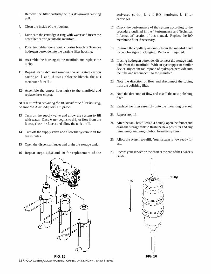
6. Remove the filter cartridge with a downward twistingpull.
7. Clean the inside of the housing.
8. Lubricate the cartridge o-ring with water and insert thenew filter cartridge into the manifold.
9. Pour: two tablespoons liquid chlorine bleach or 3 ounceshydrogen peroxide into the particle filter housing.
10. Assemble the housing to the manifold and replace theu-clip.
11. Repeat steps 4-7 and remove the activated carboncartridge ② and, if using chlorine bleach, the ROmembrane filter ③ .
12. Assemble the empty housing(s) to the manifold andreplace the u-clip(s).
NOTICE: When replacing the RO membrane filter housing,be sure the drain adaptor is in place.
13. Turn on the supply valve and allow the system to fillwith water. Once water begins to drip or flow from thefaucet, close the faucet and allow the tank to fill.
14. Turn off the supply valve and allow the system to sit forten minutes.
15. Open the dispenser faucet and drain the storage tank.
16. Repeat steps 4,5,8 and 10 for replacement of the
activated carbon ② and RO membrane ③ filtercartridges.
17. Check the performance of the system according to theprocedure outlined in the “Performance and TechnicalInformation” section of this manual. Replace the ROmembrane filter if necessary.
18. Remove the capillary assembly from the manifold andinspect for signs of clogging. Replace if required.
19. If using hydrogen peroxide, disconnect the storage tanktube from the manifold. With an eyedropper or similardevice, inject one tablespoon of hydrogen peroxide intothe tube and reconnect it to the manifold.
20. Note the direction of flow and disconnect the tubingfrom the polishing filter.
21. Note the direction of flow and install the new polishingfilter.
22. Replace the filter assembly onto the mounting bracket.
23. Repeat step 13.
24. After the tank has filled (3-4 hours), open the faucet anddrain the storage tank to flush the new postfilter and anyremaining sanitizing solution from the system.
25. Allow the system to refill. Your system is now ready foruse.
26. Record your service on the chart at the end of the Owner’sGuide.
FIG. 15 FIG. 16

TROUBLESHOOTING GUIDE / 23
Troubleshooting GuideIf a problem cannot be corrected through use of this Troubleshooting Guide and assistance from the factory isrequired, please have the following information available:
1. Product water flow rate (directly from module). 2. Concentrate flow rate (from concentrate water outlet of module housing). Pressure relief valve must be closed
when measuring concentrate flow rate. 3. Feed water line pressure.*4. Product water quality (directly from module).*5. Reservoir water quality.*6. Feed water quality. 7. Feed water temperature. 8. Reservoir precharge pressure.*Check with TDS meter PN D0-4705-04.
PROBLEM POSSIBLE CAUSE REMEDY
1. Insufficient quantity a. Service greater than a. Use optional large tank for more storageof product water unit’s specified output. capacity.available to service.
b. Insufficient feed b. 1. Clogged shut-off valve or feed tubing;water flow. clean out or replace
2. Clogged prefilter; replace.3. Clogged manifold; clean or replace.
c. Insufficient feed c. 1. Same as (b) abovewater pressure 2. Change in line pressure; install booster
pump.
d. Increase in feed water d. 1. Same as (a) above.TDS. 2. Install booster pump.
e. Reduced feed water e. Sametemperature
f. Plugged prefilter. f. Replace filter element.
g. Plugged polishing g. Replace polishing filter.filter.
h. RO membrane filter h. Replace RO membrane filter and prefilterfouled with sediment. elements.
i. Shutoff malfunction. i. Clean or replace shutoff.
2. Poor product water a. All of (1) above a. All of (1) above except (a), (e), and (g).quality except (a) and (e)
b. RO membrane filter. b. Replace RO membrane filter.worn out.

24 / AQUA-CLEER®/GOOD WATER MACHINE™ DRINKING WATER SYSTEMS
c. Bad O-ring on c. Replace O-ringRO membrane filter.
d. Shutoff malfunction. d. Replace shutoff.
3. Bad tasting product a. Decrease in product a. Same as (2) above.water quality; see (2) above.
b. Foreign matter in b. Clean, sanitize, and flush storage tank.storage tank.
c. Polishing filter c. Replace polishing filterexhausted.
d. Leakage around membrane d. Replace O-ringsfilter O-rings.
e. Plugged capillary tube. e. Replace capillary tube; replace prefilter,if necessary.
f. Storage tank bladder f. Replace storage tank and check prechargeis ruptured. pressure.
4. External leakage. a. Tubing not fully seated a. Check all fittings for tightness.in fitting
b. Tubing abraded in seal b. Recut tubing and redo connection.area.
5. Overflow at faucet air a. Concentrate tubing a. Clean concentrate tubing of debris.gap (gurgling sounds). plugged.
b. Air gap plugged. b. Clean with vinegar and/or soap.
c. Concentrate tubing not in c. Eliminate loops or low spots in tubing.continuous downwardslope.
d. Obstructed home drain d. Free obstruction.pipe.
6. Foaming at faucet tip. a. Storage tank is pos- a. Place tank in vertical position.itioned on side(Dissolved air cannotescape.)
7. Foaming at air-gap a. Concentrate tubing a. Find different drain for system.connected to same drainline as dishwasher, etc.
b. When sink is full of b. Obstructed home drain, free obstruction.soapy water and plugis pulled, can back upat air-gap.
c. Obstructed home drain c. Free obstruction

8. Bad smell from product a. Polishing filter exhausted. a. Replace polishing filter.water.
b. Prefilter element b. Replace filter element.
c. Unit needs disin- c. Sanitize unit.fection.
9. Fast flow to drain. a. Defective capillary tube. a. Replace capillary tube.
10. Black specks in a. Carbon fines. a. Flush polishing filter.product water.
11. Low faucet pressure a. Low precharge in a. Increase storage tank precharge.storage tank.
b. Polishing filter plugged. b. Replace polishing filter.
12. Capillary tube plugging a. Excessive turbidity. a. Install another 5 micron filter in series withexisting one or substitute carbon block filterfor granular activated carbon filter.
b. Iron fouled. b. Pretreat for iron removal.
c. Iron-bacteria fouled. c. Sanitize plumbing.
TROUBLESHOOTING GUIDE / 25