APX 4500 Project 25 Mobile Radio - emcotechnologies.com · That’s where the APX 4500 P25 mobile...
4
DATASHEET | APX ™ 4500 MOBILE RADIO A downed power line or the city transit system coming to a halt during rush hour, when the unexpected strikes, you must interoperate seamlessly and securely with other agencies and responders – often across multiple Project 25 (P25) systems. You need to instantly connect and be informed to make better decisions and respond effectively. While the advanced technology of APX ™ radios expertly equips you for the unexpected, your organization may be challenged to improve operating expenses. That’s where the APX 4500 P25 mobile radio fits the bill perfectly. It delivers all the benefits of TDMA technology in a compact P25 capable mobile. The APX 4500 brings together powerful technology in an easy-to-use radio that’s easy on your budget. It seamlessly unifies public works, utility, rural public safety and transportation users to first responders so they can communicate effectively in the moments that matter. CONVENIENTLY SMALL, EASY TO INSTALL The APX 4500 is designed to get the job done without getting in the way. A simplified dash mount design makes installation quick and easy, fitting into the existing XTL ™ footprint so you can reuse mounting holes and cables. Count on the APX 4500 to withstand wet, dusty and hazard- ous conditions, too. Its IP56 durability rating is the highest level of certification for uncompromising durability and world class quality in a mobile performer you can hose down. APX ™ 4500 PROJECT 25 MOBILE RADIO BE BETTER EQUIPPED TO BE MISSION READY KEEPS CREWS IN TOUCH, AND UP TO THE MINUTE Safety runs in the APX family and the APX 4500 mobile is no exception. Like all our APX P25 radios trusted by responders worldwide, the APX 4500 mobile redefines safety. Your crews can count on quick, seamless interoperability and extended range – whether they are talking from the top of a pole or the bottom of a trench. You can depend on AES encryption for secure, tamperproof voice and data communications every time they connect. With integrated GPS in the APX 4500, you can keep an eye on workers and assets you can’t see, tracking their locations continuously. The O2 control head with color display is easy to read and operate in all lighting conditions, from bright sunlight to dark streets. The intelligent lighting on the O2 control head notifies your workers when a call is received, an emergency arises, or when they are out of range. Plus, an enlarged multifunction knob makes it easy to use talk-group and volume settings when they’re wearing gloves. Over-the-air programming on the APX 4500 keeps your crews current in the field. You can update the latest mobile without interrupting voice communications while they work. SIZED RIGHT FOR YOUR BUDGET The APX 4500 lets you reuse many accessories which utilize the O5 and O3 control heads on XTL radios, so you can maximize your investment while you benefit from the latest technology. Since the APX 4500 is P25 Phase 2 capable for twice the voice capacity, you can add more users without adding more frequencies or infrastructure. It is backwards and forwards compatible with all Motorola mission critical radio systems, so you can interoperate with confidence while you improve operating expenses.
Transcript of APX 4500 Project 25 Mobile Radio - emcotechnologies.com · That’s where the APX 4500 P25 mobile...

DATASHEET | APX™ 4500 MOBILE RADIO
A downed power line or the city transit system coming to a halt during rush hour, when the unexpected strikes, you must interoperate seamlessly and securely with other agencies and responders – often across multiple Project 25 (P25) systems. You need to instantly connect and be informed to make better decisions and respond effectively. While the advanced technology of APX™ radios expertly equips you for the unexpected, your organization may be challenged to improve operating expenses.
That’s where the APX 4500 P25 mobile radio fits the bill perfectly. It delivers all the benefits of TDMA technology in a compact P25 capable mobile. The APX 4500 brings together powerful technology in an easy-to-use radio that’s easy on your budget. It seamlessly unifies public works, utility, rural public safety and transportation users to first responders so they can communicate effectively in the moments that matter.
CONVENIENTLY SMALL, EASY TO INSTALLThe APX 4500 is designed to get the job done without getting in the way. A simplified dash mount design makes installation quick and easy, fitting into the existing XTL™ footprint so you can reuse mounting holes and cables.
Count on the APX 4500 to withstand wet, dusty and hazard-ous conditions, too. Its IP56 durability rating is the highest level of certification for uncompromising durability and world class quality in a mobile performer you can hose down.
APX ™ 4500 PROJECT 25
MOBILE RADIO
BE BETTER EQUIPPED TO BE MISSION READY
KEEPS CREWS IN TOUCH, AND UP TO THE MINUTE Safety runs in the APX family and the APX 4500 mobile is no exception. Like all our APX P25 radios trusted by responders worldwide, the APX 4500 mobile redefines safety. Your crews can count on quick, seamless interoperability and extended range – whether they are talking from the top of a pole or the bottom of a trench. You can depend on AES encryption for secure, tamperproof voice and data communications every time they connect.
With integrated GPS in the APX 4500, you can keep an eye on workers and assets you can’t see, tracking their locations continuously. The O2 control head with color display is easy to read and operate in all lighting conditions, from bright sunlight to dark streets. The intelligent lighting on the O2 control head notifies your workers when a call is received, an emergency arises, or when they are out of range. Plus, an enlarged multifunction knob makes it easy to use talk-group and volume settings when they’re wearing gloves.
Over-the-air programming on the APX 4500 keeps your crews current in the field. You can update the latest mobile without interrupting voice communications while they work.
SIZED RIGHT FOR YOUR BUDGET The APX 4500 lets you reuse many accessories which utilize the O5 and O3 control heads on XTL radios, so you can maximize your investment while you benefit from the latest technology. Since the APX 4500 is P25 Phase 2 capable for twice the voice capacity, you can add more users without adding more frequencies or infrastructure. It is backwards and forwards compatible with all Motorola mission critical radio systems, so you can interoperate with confidence while you improve operating expenses.
PAGE 2
APX™ 4500 SPECIFICATIONSFEATURES AND BENEFITS:
Available in 700/800 MHz, VHF, UHFR1, UHFR2, and 900 MHz. Supports NPCS band (901-902 MHz and 940-941 MHz)
Channels: Standard 512
Trunking Standards supported: • Clear or digital encrypted Trunked Operation • Capable of SmartZone®, SmartZone Omnilink, SmartNet®
Analog MDC-1200 and Digital APCO P25 Conventional System Configurations
Narrow and wide bandwidth digital receiver (6.25kHz/12.5kHz/25kHz/30 kHz)
Embedded digital signaling (ASTRO and ASTRO 25)
Integrated Encryption Hardware
Integrated GPS/GLONASS for outdoor location tracking
Intelligent lighting
Radio profiles
Unified Call List
Meets applicable MIL-STD 810C, D, E, F, G
Ships standard IP56
Utlizes Windows XP, Vista and Windows 7 Customer Programming Software (CPS)
• Supports USB Communications • Built in FLASHport™ support
Re-use of most XTL™ accessories, plus new IMPRES accessories
OPTIONAL FEATURES:
AES Encryption
Programming over Project 25 (POP25)
Text Messaging
12 character RF ID asset tracking
Tactical OTAR
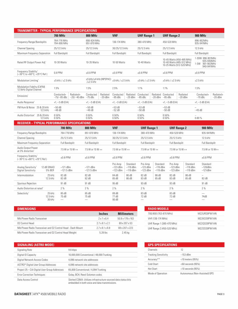
O2 RUGGED CONTROL HEAD
Large color display with intelligent lighting
3 lines of text 14 characters max / 1 line of icons / 1 line of menus
Built in 7.5 watt speaker
Multifunction volume/channel knob
Night/day mode button
APX 4500 CONTROL HEAD PORTFOLIO
DATASHEET | APX™ 4500 MOBILE RADIO
PAGE 3
GPS SPECIFICATIONSChannels 12
Tracking Sensitivity –153 dBm
Accuracy** <10 meters (95%)
Cold Start <60 seconds (95%)
Hot Start <10 seconds (95%)
Mode of Operation Autonomous (Non-Assisted) GPS
DIMENSIONSInches Millimeters
Mid Power Radio Transceiver 2 x 7 x 6.4 50.8 x 178 x 163
O2 Control Head 2.7 x 8.1 x 2.1 69 x 207 x 53
Mid Power Radio Transceiver and O2 Control Head - Dash Mount 2.7 x 8.1 x 8.8 69 x 207 x 223
Mid Power Radio Transceiver and O2 Control Head Weight 5.28 lbs 2.45 kg
TRANSMITTER - TYPICAL PERFORMANCE SPECIFICATIONS700 MHz 800 MHz VHF UHF Range 1 UHF Range 2 900 MHz
Frequency Range/Bandsplits 764-776 MHz 794-806 MHz
806-824 MHz 851-870 MHz 136-174 MHz 380-470 MHz 450-520 MHz 896-902MHz
935-941MHz
Channel Spacing 25/12.5 kHz 25/12.5 kHz 30/25/12.5 kHz 25/12.5 kHz 25/12.5 kHz 12.5 kHz
Maximum Frequency Separation Full Bandsplit Full Bandsplit Full Bandsplit Full Bandsplit Full Bandsplit Full Bandsplit
Rated RF Output Power Adj* 10-30 Watts 10-35 Watts 10-50 Watts 10-40 Watts10-45 Watts (450-485 MHz) 10-40 Watts (485-512 MHz)10-25 Watts (512-520 MHz)
1-30W 896-901MHz 935-940MHz1-3W 901-902MHz 940-941MHz
Frequency Stability*
(–30°C to +60°C; +25°C Ref.) 0.8 PPM ±0.8 PPM ±0.8 PPM ±0.8 PPM ±0.8 PPM ±0.8 PPM
Modulation Limiting* ±5 kHz / ±2.5 kHz ±5 kHz/±4 kHz (NPSPAC) /±2.5 kHz ±5 kHz / ±2.5 kHz ±5 kHz / ±2.5 kHz ±5 kHz / ±2.5 kHz ±2.5 kHz
Modulation Fidelity (C4FM)12.5kHz Digital Channel 1.5% 1.5% 2.5% 1.1% 1.1% 1.5%
Emissions* Conducted+ –75/–85 dBc
Radiated+ –20/–40 dBm
Conducted –75 dBc
Radiated –20 dBm
Conducted –85 dBc
Radiated –20 dBm
Conducted –85 dBc
Radiated –20 dBm
Conducted –85 dBc
Radiated –20 dBm
Conducted+ –70 dBc
Radiated+ –20 dBm
Audio Response* +1, –3 dB (EIA) +1, –3 dB (EIA) +1, –3 dB (EIA) +1, –3 dB (EIA) +1, –3 dB (EIA) +1, –3 dB (EIA)
FM Hum & Noise 25 & 20 kHz 12.5 kHz
–50 dB –48 dB
–50 dB –48 dB
–53 dB –52 dB
–53 dB –50 dB
–53 dB –50 dB
– –45 dB
Audio Distortion* 25 & 20 kHz 12.5 kHz
0.50%0.50%
0.50%0.50%
0.50%0.50%
0.50%0.50%
0.50%0.50%
– 0.80 %
RECEIVER – TYPICAL PERFORMANCE SPECIFICATIONS700 MHz 800 MHz VHF UHF Range 1 UHF Range 2 900 MHz
Frequency Range/Bandsplits 764-776 MHz 851-870 MHz 136-174 MHz 380-470 MHz 450-520 MHz 935-941MHz
Channel Spacing 25/12.5 kHz 25/12.5 kHz 30/25/12.5 kHz 25/12.5 kHz 25/12.5 kHz 12.5 kHz
Maximum Frequency Separation Full Bandsplit Full Bandsplit Full Bandsplit Full Bandsplit Full Bandsplit Full Bandsplit
Audio Output Power at 3% distortion* 7.5 W or 15 W ++ 7.5 W or 15 W ++ 7.5 W or 15 W ++ 7.5 W or 15 W ++ 7.5 W or 15 W ++ 7.5 W or 15 W++
Frequency Stability*
(–30°C to +60°C; +25°C Ref.) ±0.8 PPM ±0.8 PPM ±0.8 PPM ±0.8 PPM ±0.8 PPM ±0.8 PPM
Analog Sensitivity* 12 dB SINAD Digital Sensitivity 5% BER
–121 dBm –121.5 dBm
–121 dBm –121.5 dBm
Pre-Amp –123 dBm –123 dBm
Standard –119 dBm –119 dBm
Pre-Amp –123 dBm –123 dBm
Standard –119 dBm –119 dBm
Pre-Amp –123 dBm –123 dBm
Standard –119 dBm –119 dBm
Standard–120dBm–121dBm
Intermodulation 25 kHz 12.5 kHz
82 dB 82 dB
82 dB 82 dB
84 dB 85 dB
86 dB 86 dB
82 dB 83 dB
86 dB 85 dB
82 dB 83 dB
86 dB 85 dB
– 82 dB
Spurious Rejection 91 dB 91 dB 95 dB 93 dB 93 dB 91 dB
Audio Distortion at rated* 2 % 2 % 2 % 2 % 2 % 2 %
Selectivity* 25 kHz 12.5 kHz 30 kHz
85 dB 75 dB —
85 dB 75 dB —
89 dB 77 dB 90 dB
83 dB 72 dB —
83 dB 72 dB —
—74dB—
SIGNALING (ASTRO MODE)Signaling Rate 9.6 kbps
Digital ID Capacity 10,000,000 Conventional / 48,000 Trunking
Digital Network Access Codes 4,096 network site addresses
ASTRO® Digital User Group Addresses 4,096 network site addresses
Project 25 – CAI Digital User Group Addresses 65,000 Conventional / 4,094 Trunking
Error Correction Techniques Golay, BCH, Reed-Solomon codes
Data Access Control Slotted CSMA: Utilizes infrastructure-sourced data status bits embedded in both voice and data transmissions.
RADIO MODELS700/800 (763-870 MHz) M22URS9PW1AN
VHF (136-174 MHz) M22KSS9PW1AN
UHF Range 1 (380-470 MHz) M22QSS9PW1AN
UHF Range 2 (450-520 MHz) M22SSS9PW1AN
DATASHEET | APX™ 4500 MOBILE RADIO
ENCRYPTIONSupported Encryption Algorithms AES and ADP
Encryption Algorithm Capacity Single
Encryption Keys per Radio Module capable of storing 1024 keys. Programmable for 64 Common Key Reference (CKR) or 16 Physical Identifier (PID)
Encryption Frame Re-sync Interval P25 CAI 300 mSec
Encryption Keying Key Loader
Synchronization XL – Counter Addressing, OFB – Output Feedback
Vector Generator National Institute of Standards and Technology(NIST) approved random number generator
Encryption Type Digital
Key Storage Tamper protected volatile or non-volatile memory
Key Erasure Keyboard command and tamper detection
Standards FIPS 140-2 Level 3FIPS 197
ENVIRONMENTAL SPECIFICATIONSOperating Temperature -30ºC / +60ºC
Storage Temperature -40ºC / +85ºC
Humidity Per MIL-STD
ESD IEC 801-2 KV
Water and Dust Intrusion IP56, MIL-STD
MOTOROLA, MOTOROLA SOLUTIONS, and the stylized M Logo are trademarks or registered trademarks of Motorola Trademark Holdings, LLC and are used under license. All other trademarks are the property of their respective owners. © Motorola Solutions, Inc. 2016. 07-2016
Motorola Solutions, Inc. 1301 E. Algonquin Road, Schaumburg, Illinois 60196 U.S.A. www.motorolasolutions.com
* Measured in the analog mode per TIA/EIA 603 under nominal conditions** Accuracy specs are for long-term tracking (95th percentile values >5 satellites visible at a nominal –130 dBm signal strength)+ Specs includes performance for the non-GNSS/GNSS bands++ Output power in to 8 and 3.2 Ohm external speakers respectively
Specifications subject to change without notice. All specifications shown are typical. Radio meets applicable regulatory requirements.
MOBILE MILITARY STANDARDS 810 C, D, E , F, GMIL-STD 810C MIL-STD 810D MIL-STD 810E MIL-STD 810F MIL-STD 810G
Method Proc./Cat. Method Proc./Cat. Method Proc./Cat. Method Proc./Cat. Method Proc./Cat.Low Pressure 500.1 I 500.2 II 500.3 II 500.4 II 500.5 II
High Temperature Storage 501.1 I 501.2 I/A1 501.3 I/A1 501.4 I/Hot 501.5 I/A1
High Temperature Operation 501.1 II 501.2 II/A1 501.3 II/A1 501.4 II/Hot 501.5 II
Low Temperature Storage 502.1 I 502.2 I/C3 502.3 I/C3 502.4 I/C3 502.5 I/C3
Low Temperature Operation 502.1 I 502.2 II/C1 502.3 II/C1 502.4 II/C1 502.5 II
Temperature Shock 503.1 - 503.2 I/A1-C3 503.3 I/A1-C3 503.4 I/Hot-C3 503.5 I/C
Solar Radiation 505.1 II 505.2 I 505.3 I 505.4 I 505.5 I/A1
Rain Blowing 506.1 I 506.2 I 506.3 I 506.4 I 506.5 I
Rain Steady 506.1 II 506.2 II 506.3 II 506.4 III 506.5 III
Humidity 507.1 II 507.2 II 507.3 II 507.4 - 507.5 II-Aggravated
Salt Fog 509.1 - 509.2 - 509.3 - 509.4 - 509.5 1 Proc
Blowing Dust 510.1 I 510.2 I 510.3 I 510.4 I 510.5 I
Blowing Sand - 510.2 II 510.3 II 510.4 II 510.5 II
Vibration Min. Integrity 514.2 VIII/F, Curve-W 514.3 I/10 514.4 I/10 514.5 I/24 514.6 I-Cat.24
Vibration Loose Cargo 514.2 XI 514.3 II/3 514.4 II/3 514.5 II/5 514.6 -
Shock Functional 516.2 I 516.3 I 516.4 I 516.5 I 516.6 I, V, VI
POWER AND BATTERY DRAINModel Type 136-174 MHz, 380-470 MHz, 450-520 MHz, 764-870 MHz, 896-941MHz
Minimum RF Power Output 2-30 Watts (764-776 MHz), 2-30 Watts (794-806 MHz), 2-35 Watts (806-824 MHz), 2-35 Watts (851-870 MHz), 1-50 Watts (136-174 MHz).1-40 Watts (380-470 MHz), 1-45 Watts (450-485 MHz), 1-40 Watts (485-512 MHz), 1-25 Watts (512-520 MHz), 1-30Watts (896-901MHz),1-3Watts (901-902MHz), 1-30W (935-940MHz), 1-3Watts (940-941MHz)
Operation 13.8V DC ±20% Negative Ground
Standby at 13.8V 0.85A (764-870 MHz), 0.85A (136-174 MHz), 0.85A (380-470 MHz), 0.85A (450-520 MHz)
Receive Current at Rated Audio at 13.8V 3.2A (764-870 MHz), 3.2A (136-174 MHz), 3.2A (380-470 MHz), 3.2A (450-520 MHz)
Transmit Current (A) at Rated Power 136-174 MHz (10-50 Watt) 380-470 MHz (10-40 Watt) 380-470 MHz (10-40 Watt)
13A (50W) 11A (40W) 11A (45W)
8A (15W) 8A (15W) 8A (15W)
764-870 MHz (2***-35W)896-901MHz (1-30W)935-940MHz(1-30W)901-902MHz(1-3W)940-941MHz( 1-3W)
12A (35W)10A (30W)10A (30W)5A (3W)5A (3W)
8A (15W)7A(15W)7A(15W)
TRANSMITTER CERTIFICATION700/800 (764-775, 793-805, 806-824, 851-869 MHz) AZ492FT7055
VHF (136-174 MHz) AZ492FT3826
UHF R1 (380-470 MHz) AZ492FT4915
UHF R2 (450-520 MHz) AZ492FT4916
900 MHz (896-901, 901-902,935-940, 940-941 MHz) AZ492FT5865
FCC EMISSIONS DESIGNATORSFCC Emissions Designators 8K10F1D, 8K10F1E, 8K10F1W,
11K0F3E, 16K0F3E, 20K0F1E,10K0F3E (for AZ492FT5865 only)