
MDK-ARM Microcontroller Development Kit MDK: Microcontroller Development Kit.

AUTOMATIC ROOM POWER CONTROL WITH VISITOR COUNTER
A REPORT ON
AUTOMATIC ROOM POWER CONTROL WITH VISITOR COUNTER
APRIL 2012
CERTIFICATE
This is to certify that the project report entitles
“AUTOMATIC ROOM POWER CONTROL WITH VISITOR COUNTER”
20121 | P a g e

AUTOMATIC ROOM POWER CONTROL WITH VISITOR COUNTER
CONTENTS
CERTIFICATE IACKNOWLEDGEMENT II
CHAPTER TITLE PAGE NO
1. INTRODUCTION 51.1 BACKGROUND 51.2 RELEVANCE 5
2. OBJECTIVES 6
3. ASSUMPTIONS 7
4. BLOCK DIAGRAM 84.1 BLOCK DIAGRAM DESCRIPTION 8
4.1.1 POWER SUPPLY 94.1.2 ENTER EXIT CIRCUIT 94.1.3 MICROCONTROLLER 89S52 94.1.4 RELAY 9
4.2 OPERATION FLOWCHART 10
5. CIRCUIT DIAGRAM 125.1 DESCRIPTION 12
5.1.1 MICROCONTROLLER 89S52 125.1.2 RELAY CIRCUIT 145.1.3 VOLTAGE REGULATOR 155.1.4 POWER SUPPLY DESIGN 16
5.2 SPECIFICATIONS OF THE PROJECT 17
6. PROGRAM LOGIC DESCRIPTION 196.1 BEHIND THE SCENE 19
6.1.1 ENTER 206.1.2 EXIT 206.1.3 POWER SUPPLY SWITCHING 20
7. PCB LAYOUT AND CONNECTIONS 217.1 LAYOUT METHODOLOGY 21
20122 | P a g e

AUTOMATIC ROOM POWER CONTROL WITH VISITOR COUNTER
7.1.1 GENERAL RULES FOR DESIGN 22ABSTRACT
With the advent of Technology the human life becomes very easier and simple.
Along with fulfillment of the basic technical needs, providing the luxury in any
environment becomes very important thing. Now days electronic is playing very
important role in managing all these things. This project also completes the requirement
of easiness, comfort and safety. This project is a basically a controller which is consisting
of the same Enter and Exit door which we can connect in any domestic,commercial or
educational centerswhich will save the wastage of Power,Time and Manpower
requirement .
For many years in the field of commercial, domestic and education we have to
work out manually with different counting techniques for the visitors. It has always been
a challenge for the institution to detect the exact no of persons entering the events. So this
project aims at a certain parameter of counting the number of persons visited the event.
Also the project is capable of switching the main power supplies if the power is not
required. It fulfills the modern need of automation and resourse utilization.
This project is the based example of the fact that how modern electronic has
secured the human life. There is heavy duty of scope for this control panel in future.
20123 | P a g e
AUTOMATIC ROOM POWER CONTROL WITH VISITOR COUNTER
1.INTRODUCTION1.1 BACKGROUND:
In todays world there is great need of automating the things. As the world has become
faster and closer, the SMART work is always appretiated. So here we have made an
attempt be the instrument for such a particular kind of need.As the technology progress
the nature of the human being is to search for happiness, comfort and the luxurious life.
Though the technology has both the sides that is advantages and certain disadvantages,
the human being is always inclined towards the positive side of it.
1.2 RELEVANCE
Visitor counter is one of the premium way to count the quantity of the respective. These
systems are widely used in the shopping malls where large number of people visit the
shopping mall every day. These types of systems plays a vital role in defining the
capacity of the shopping mall and also helps to maintain the security check in such a big
shopping complexes. These types of systems are also used in other crowed places like
airports, bus stands, cinema halls, railway stations etc. This system helps to check that
how many people are present inside the area under observation. At the time of some
disaster, these systems are very helpful in determining the causalities and evacuation
system. This project serves a great need of resourse utilization. As if there are no vistors
inside the room or the number of persons inside the room are zero then automatically the
main power supply is switched to off. As soon as there is a need of power, that is when
the first person enters the room the power is switched to on state.
This project is based on the use of the Ic 89s52 microcontroller. This
microcontroller is gives a very great flexibily and syncronises with the projects output
needs. It gives us much faster responses, and also the on and off action swiching is done
efficiently. In future we have much more scope to the concept.
20124 | P a g e
AUTOMATIC ROOM POWER CONTROL WITH VISITOR COUNTER
2. OBJECTIVES
The project is counting the visitors and the controlling the power usage. Thus it
provides us with the following objectives.
Count the number of persons entering the room.
Count the number of persons leaving the room.
Switch OFF the Power Supply if no one inside the Room
Switch ON the Power Suppyeven if a single person is inside the Room.
20125 | P a g e

AUTOMATIC ROOM POWER CONTROL WITH VISITOR COUNTER
3. ASSUMPTIONS
There is only one door for enter and exit.
Two persons cannot enter simultaneously
As the ‘ir sensors’ are used it can count the object as well as the persons.
But in our case we assume that only persons are entering the room.
20126 | P a g e
AUTOMATIC ROOM POWER CONTROL WITH VISITOR COUNTER
4.BLOCK DIAGRAM
Fig 4.0
4.1 BLOCK DIAGRAM DESCRIPTION :
This system basically consist of –
1. Two IR sensors (required for enter and exit detection) ,
2. One LCD 16x2, (required for displaying the count)
3. 2 Relay, (required for controlling the power supply)
4. Microcontroller IC 89s52 (40 pin Controller IC)
20127 | P a g e

AUTOMATIC ROOM POWER CONTROL WITH VISITOR COUNTER
4.1.1 Power Supply:-
Here we used +12V and +5V dc power supply. The main function
of this block is to provide the required amount of voltage to essential
circuits. +12 voltage is given. +12V is given to relay driver. To get the
+5V dc power supply we have used here IC 7805, which provides the +5V
dc regulated power supply.
4.1.2 Enter and Exit Circuits:-
This is one of the main part of our project. The main intention of
this block is to sense the person. For sensing the person and light we are
using the IR sensors. By using this sensor and its related circuit diagram
we can count the persons.
4.1.3 89S52 Microcontroller:-
It is a low-power, high performance CMOS 8-bit microcontroller
with 8KB of Flash Programmable and Erasable Read Only Memory
(PEROM). The device is manufactured using Atmel’s high-density
nonvolatile memory technology and is compatible with the MCS-51TM
instruction set and pin out. The on-chip Flash allows the program memory
to be reprogrammed in-system or by a conventional nonvolatile memory
programmer. By combining a versatile 8-bit CPU with Flash on a
monolithic hip, the Atmel AT89S52 is a powerful
Microcontroller, which provides a highly flexible and cost
effective solution so many embedded control applications.4.1.4 Relay Driver Circuit:-
This block has the potential to drive the various controlled devices.
In this block mainly we are using the transistor and the relays. One relay
driver circuit we are using to control the light. Output signal from
AT89S52 is given to the base of the transistor, which we are further
20128 | P a g e

AUTOMATIC ROOM POWER CONTROL WITH VISITOR COUNTER
energizing the particular relay. Because of this appropriate device is
selected and it do its allotted function.
4.2 OPERATION FLOWCHART
Fig 4.1
20129 | P a g e

AUTOMATIC ROOM POWER CONTROL WITH VISITOR COUNTER
1. In this system, one Ir sensor is used to count the number of people getting in to
the room , which is placed at the entrance . Other Ir sensor is used to count
number of people going out of room and is placed at the exit of the room.
2. With each person getting inside the complex, the Ir1 sensor will increase the
number of count indicating the number of people present inside the complex at
the respective time period.
3. With each person going out of the complex, the Ir2 sensor will decrease the count,
maintaining the present strength of the people inside complex.
4. With each count the relay will switch on the Power and supply will start. Lcd is
used to show the count value of the persons present inside the complex.
201210 | P a g e

AUTOMATIC ROOM POWER CONTROL WITH VISITOR COUNTER
5. CIRCUIT DIAGRAM
Fig 5.0
5.1 CIRCUIT DIAGRAM DESCRIPTION:
5.1.1 Microcontroller IC 89s52
To drive the microcontroller we require certain circuits to be connected
Pin 1-8 –Port 1 Pin 9- Reset Pin 10-17 -Port 3
201211 | P a g e

AUTOMATIC ROOM POWER CONTROL WITH VISITOR COUNTER
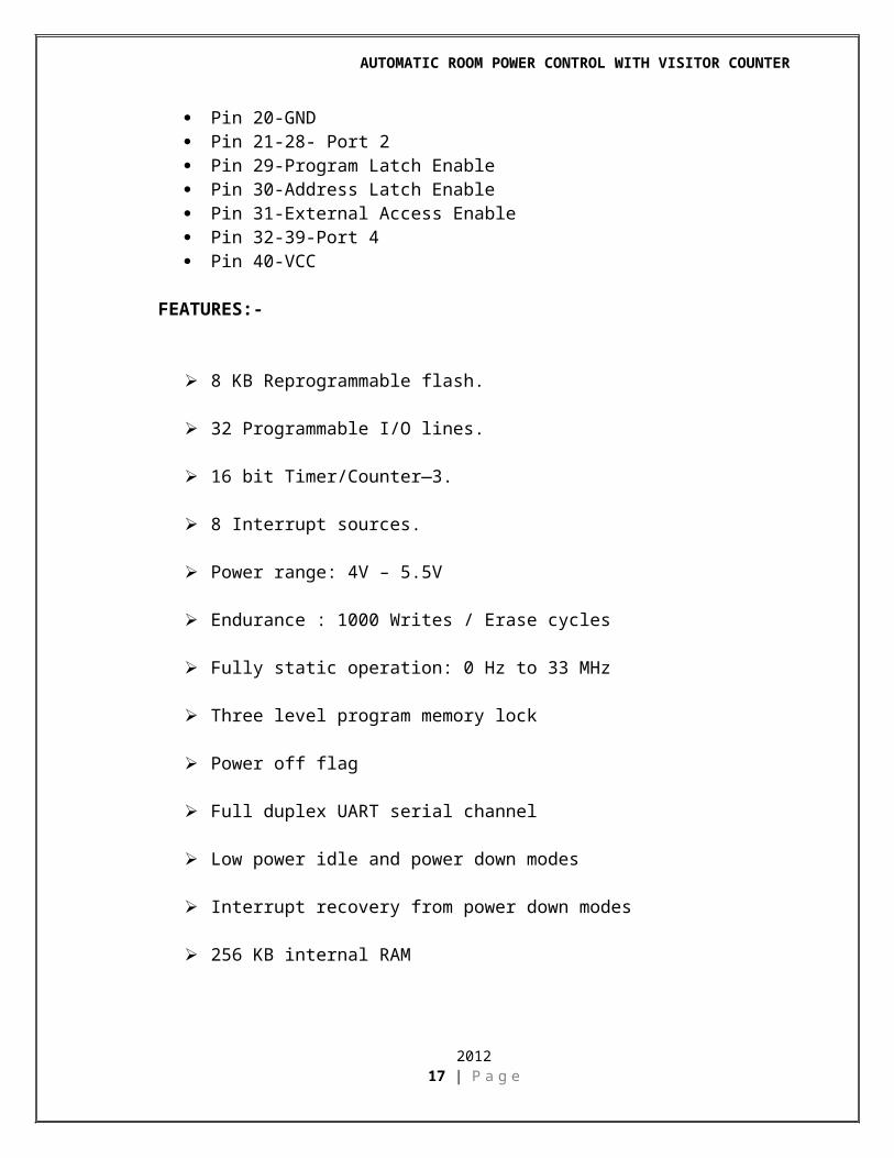
Pin 18-19 – Crsytal Oscillator Pin 20-GND Pin 21-28- Port 2 Pin 29-Program Latch Enable Pin 30-Address Latch Enable Pin 31-External Access Enable Pin 32-39-Port 4 Pin 40-VCC
FEATURES:-
8 KB Reprogrammable flash.
32 Programmable I/O lines.
16 bit Timer/Counter—3.
8 Interrupt sources.
Power range: 4V – 5.5V
Endurance : 1000 Writes / Erase cycles
Fully static operation: 0 Hz to 33 MHz
Three level program memory lock
Power off flag
Full duplex UART serial channel
Low power idle and power down modes
Interrupt recovery from power down modes
256 KB internal RAM
Dual data pointer
201212 | P a g e

AUTOMATIC ROOM POWER CONTROL WITH VISITOR COUNTER
5.1.2 Relay Circuit:
Fig. 5.1 Relay
A single pole dabble throw (SPDT) relay is connected to port RB1
of the microcontroller through a driver transistor. The relay requires 12
volts at a current of around 100ma, which cannot provide by the
microcontroller. So the driver transistor is added. The relay is used to
operate the external solenoid forming part of a locking device or for
operating any other electrical devices. Normally the relay remains off. As
soon as pin of the microcontroller goes high, the relay operates. When the
relay operates and releases. Diode D2 is the standard diode on a
mechanical relay to prevent back EMF from damaging Q3 when the relay
releases. LED L2 indicates relay on.
201213 | P a g e

AUTOMATIC ROOM POWER CONTROL WITH VISITOR COUNTER
5.1.3 LM7805 (Voltage Regulator)
Fig. 5.2 Voltage Regulator
Description:The KA78XX/KA78XXA series of three-terminal
positiveregulator are available in the TO-220/D-PAK package andwith
several fixed output voltages, making them useful in a wide range of
applications. Each type employs internalcurrent limiting, thermal shut
down and safe operating area protection, making it essentially
indestructible. If adequate heat sinking is provided, they can deliver over
1A output current. Although designed primarily as fixed voltage
regulators, these devices can be used with external components to obtain
adjustable voltages and currents.
Features: Output Current up to 1A
Output Voltages of 5, 6, 8, 9, 10, 12, 15, 18, 24V
Thermal Overload Protection
Short Circuit Protection
Output Transistor Safe Operating Area Protection
201214 | P a g e

AUTOMATIC ROOM POWER CONTROL WITH VISITOR COUNTER
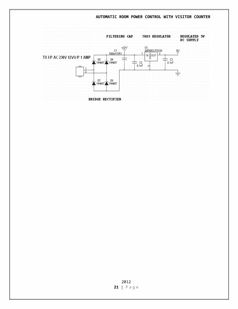
5.1.4 Power Supply Design
201215 | P a g e

AUTOMATIC ROOM POWER CONTROL WITH VISITOR COUNTER
5.2 SPECIFICATIONS OF THE PROJECT:
Microcontroller 89s52:
1> Cheap
2> Easily available
3> Programmer available in college
4> Plenty guidance available
Relay:
1> 12V Relay
2> Single Change Over
3> O/P:- 230V, 5 AMP.
LCD :-
1> LAMPEX
2> 16*2
3> Backlight Facility.
4> 100mAmp Consumption.
IR Sensor:
1. TX.àIR LED
2. RX.àIR DIODE
3. Range 5 cm
Crystal : 11.0592 MHz
201216 | P a g e
AUTOMATIC ROOM POWER CONTROL WITH VISITOR COUNTER
6. PROGRAM LOGIC ALGORITHM
6.1 BEHIND THE SCENE:
The working of the whole circuit is based upon the Logic we apply during
programming. The program can control the hardware as required by the user.
201217 | P a g e

AUTOMATIC ROOM POWER CONTROL WITH VISITOR COUNTER
So the Program logic is provided in order to understand the program
efficiently.
1. Enter:
As per the program logic (downloaded in the microcontroller),
when the first person enters the room the IR 1 detects it.
Then the person passes through the IR2 sensor which detects it.
The microcontroller checks whether it is first detected by IR1. If
yes then increment the count by 1.
If no then it remains in the loop and no change.
2. Exit
As per the program logic (downloaded in the microcontroller),
when the first person Exits the room the IR 2 detects it.
Then the person passes through IR1 sensor which detects it.
The microcontroller checks whether it was first detected by IR2. If
yes then decrement the count by 1.
If no then it remains in loop and no change.
3. Power Supply Switching
When the first person enters the room immediately the count
increases by 1(initially 0). Thus the command goes to the
microcontroller to switch ON the Relay. Thus the Relay controls
the main Power Supply Switch.
Similarly,
When all the persons inside the room Exit or if no one is in the
room(i.e count=0) then the microcontroller again gives the
command to the Relay to switch OFF.
Thus the objectives of the project are satisfied.
201218 | P a g e

AUTOMATIC ROOM POWER CONTROL WITH VISITOR COUNTER
7. PCB LAYOUT AND CONNECTIONS
7.1 LAYOUT METHODOLOGY:
For proper layout design minimal steps to be followed are:1. Get the final circuit diagram and component list.2. Choose the board types, single sided / double sided / multilayer3. Identify the appropriate scale for layout.4. Select suitable grid pattern.5. Choose the correct board size keeping in view the constraints.6. Select appropriate layout technique, manual / automated.7. Document in the form of the layout scale.
201219 | P a g e

AUTOMATIC ROOM POWER CONTROL WITH VISITOR COUNTER
7.1.1 General Rules For Designing1. Minimum spacing between conductor and pad should be 0 / 35 mm in
1:1 scale .
2. Minimum spacing between parallel conductors should be 0.4 mm in
1:1 scale.
3. The area of non-PTH solder pad should not be less than 5 sq.mm.
4. The width of current carrying conductors should be determined for
max.. temp. rise of 20 Cْ .
201220 | P a g e
AUTOMATIC ROOM POWER CONTROL WITH VISITOR COUNTER
LIST OF COMPONENTS AND COST ESTIMATION
Component Specification Qty Rate Cost( Rs.) (Rs.)
Diodes 1N4007 4 4 8Microcontroller AT 89c52 1 70 70
Capacitors 33pf ceramic 5 0.5 4.5- 104 ceramic 5 0.5 4.5- 103 ceramic 5 0.5 4.5
Resistors - 15 1 20Crystal 11.0592Mhz 2 8 16
Connectors(32pins) 32
Ir sensors 5cm range 2 25 50mountings 40 pin 1 10 10heat sinks 4*3 2 4 8
PCB - 3 350 350Multistrand Wire - 2 meters 9/meter 18
-Voltage Regulator 7805 1 10 10
Relay 12 Vdc 4 30 120LCD 16*2 1 180 180
Transformer 15 Vac , 500ma 1 80 80Regulator 7805 1 18 18
Relimate 2 pin 5 3 15Relimate 4 pin 4 5 20
Tie Cables 8 cm 1 pack 70 70
Out fittings chassy,nuts, 1 pack 270 270Bolts, screws.
TOTAL COST 1378/-
201221 | P a g e

AUTOMATIC ROOM POWER CONTROL WITH VISITOR COUNTER
APPLICATIONS, ADVANTAGES & DISADVANTAGES
Applicationo For counting purposes
o For automatic room light control
Advantageso Low cost
o Easy to use
o Implement in single door
o Automation and no requirement of separate monitoring
Disadvantageso It is used only when one single person cuts the rays of the sensor hence
it cannot be used when two person cross simultaneously.
201222 | P a g e

AUTOMATIC ROOM POWER CONTROL WITH VISITOR COUNTER
BIBLIOGRAPHY & REFERENCES
a) The 8051 Micro controller Architecture, Programming & Applications Pen ram
International By - Kenneth J. Ayala
b) The 8051 Micro controller and Embedded SystemsPearson Education By –M.A.
Mazidi
a) Atmel data book
b) Websites :
a) www.nationalsemiconductors.com
b) www.atmel.com
c) www.google.com
www.webanswers.com/.../differences-between-89s52-microcontroller-and-89c51-
microcontroller
www.8051projects.net/forum-t7442.html
www.electro-tech-online.com/.../97856-microcontroller-89s52.html
www.engineersgarage.com/sites/default/files/ LCD %20 16x2 .pdf
www. datasheet catalog.com/ datasheets .../-/ LCD -016M002B .
201223 | P a g e

AUTOMATIC ROOM POWER CONTROL WITH VISITOR COUNTER
CONCLUSION
Thus we have completed the project ‘Automatic Room Power control with Visitor Counter’ successfully. We also did the analysis and synthesis of each and every component required for the project. The refrences were taken from internet and the refrence books which were suggested by our guide. It is said that the success lies within the will, thus was implemented by me and my fellow project partners. All the things to make the project efficient from every angle were done. Thus we have got a very good guidance from our project guide to complete this project on time and with required efforts.
Thank you !!
201224 | P a g e