April 25, 2014 155 Dow St. Manchester, NH 03101 Attn: Ron ...
11
April 25, 2014 Lavallee Brensinger Architects 155 Dow St. Manchester, NH 03101 Attn: Ron Lamarre Re: North Hampton Fire Department, 235 Atlantic Avenue, North Hampton, NH Preliminary Structural Review and Assessment Dear Ron, I visited the North Hampton Fire Department on behalf of Foley Buhl Roberts & Associates (FBRA) on the morning of April 24, 2014 and conducted a 2 hour review of the building structure. This assessment was conducted per request of Lavallee Brensinger Architects in conjunction with an overall review of this facility. During this visit I spoke with Fire Chief Dennis Cote, who provided me with access to various areas of the building. There are no available original construction drawings of this facility. This inspection was conducted by visual means, using a tape measure, a stepladder and a digital camera. No exploratory demolition or materials sampling or testing was conducted for this assessment. This assessment included the Fire Department building only. There is a connecting link that connects this building to the adjacent Police/Municipal Office building, however that link was constructed more recently (circa 1990) as part of the Police/Municipal Office building and I understand the facilities within that link are only occasionally used (shared) by the Fire Department. The Fire Department is a one-story, rectangular, gable-roofed building, reportedly built circa 1960. The building measures approximately 60 feet wide by 106 feet long, for a gross floor area of about 6400 square feet. The apparatus bay accounts for roughly 70% of the overall building footprint. Vehicular access to the apparatus bay is provided by three overhead doors in the south gable end of the building. The entire floor is a grade-supported concrete slab. The exterior walls are comprised of 8” concrete masonry, with a 4” brick veneer. The east and west exterior walls of the building are load-bearing and they support a clear span (60’) roof structure comprised of prefabricated dimensional lumber (2x) wood trusses spaced at 2’-0” on centers, with a plywood roof deck. The east side of the building is partitioned into various smaller spaces that include bunk and shower facilities, a kitchen, office, radio and a ready-room. These spaces are separated from the apparatus bay by an interior concrete masonry wall. These areas have a ceiling height of
Transcript of April 25, 2014 155 Dow St. Manchester, NH 03101 Attn: Ron ...

April 25, 2014 Lavallee Brensinger Architects 155 Dow St. Manchester, NH 03101 Attn: Ron Lamarre Re: North Hampton Fire Department, 235 Atlantic Avenue, North Hampton, NH Preliminary Structural Review and Assessment Dear Ron, I visited the North Hampton Fire Department on behalf of Foley Buhl Roberts & Associates (FBRA) on the morning of April 24, 2014 and conducted a 2 hour review of the building structure. This assessment was conducted per request of Lavallee Brensinger Architects in conjunction with an overall review of this facility. During this visit I spoke with Fire Chief Dennis Cote, who provided me with access to various areas of the building. There are no available original construction drawings of this facility. This inspection was conducted by visual means, using a tape measure, a stepladder and a digital camera. No exploratory demolition or materials sampling or testing was conducted for this assessment. This assessment included the Fire Department building only. There is a connecting link that connects this building to the adjacent Police/Municipal Office building, however that link was constructed more recently (circa 1990) as part of the Police/Municipal Office building and I understand the facilities within that link are only occasionally used (shared) by the Fire Department. The Fire Department is a one-story, rectangular, gable-roofed building, reportedly built circa 1960. The building measures approximately 60 feet wide by 106 feet long, for a gross floor area of about 6400 square feet. The apparatus bay accounts for roughly 70% of the overall building footprint. Vehicular access to the apparatus bay is provided by three overhead doors in the south gable end of the building. The entire floor is a grade-supported concrete slab. The exterior walls are comprised of 8” concrete masonry, with a 4” brick veneer. The east and west exterior walls of the building are load-bearing and they support a clear span (60’) roof structure comprised of prefabricated dimensional lumber (2x) wood trusses spaced at 2’-0” on centers, with a plywood roof deck. The east side of the building is partitioned into various smaller spaces that include bunk and shower facilities, a kitchen, office, radio and a ready-room. These spaces are separated from the apparatus bay by an interior concrete masonry wall. These areas have a ceiling height of

Lavallee Brensinger Architects North Hampton Fire Station Preliminary Structural Review and Assessment April 25, 2014 Page 2 of 11
approximately 8 feet. The space above this ceiling is accessible (using a ladder) from the apparatus bay and is used, in part, for light storage. Rooms at the northerly end (rear) of the building include the boiler room, the hose tower and the Chief’s office. The hose tower is comprised entirely of concrete block construction and it extends above the ridge line of the main roof. There is a radio antenna tower on the roof. This tower bears directly on the roof deck, although it is also attached to the side of the hose tower at two elevations. The tower is guyed in three directions. The building has residential-scale punched window openings, with loose steel angle lintels supporting the masonry over the windows. Wood Truss Roof System The roof of the Fire Station is comprised of asphalt shingle roofing over a plywood roof deck, supported by prefabricated wood roof trusses. With the exception of the trusses on either side of the hose tower, the trusses can be described as follows:
• 60’ clear span gable trusses, symmetric about the main ridge line.
• Trusses bear on the east and west exterior masonry walls of the building.
• 4V:12H top chord pitch
• Horizontal bottom chord at the level of the apparatus bay ceiling.
• Insulation is in the plane of the bottom chord.
• Pratt truss configuration, with the panel size being approximately 6 spaces @ 10 feet.
The roof trusses are comprised of dimensional lumber, believed (by inspection) to be Southern Pine. Member sizes are as follows: Top chord: 2x8 Bottom chord: 2x6 Web verticals: 2x4 Web diagonals: 2x6 Very few legible grade stamps were found during this inspection. However, based on the stamps that were found, the web diagonal members are No. 2 grade and are rated for an allowable flexural stress of 1500 psi. These roof trusses are fabricated with plywood gusset plates (as opposed the metal plate connectors found on more recent prefabricated wood trusses). The gusset plates are ½” thick and are glued and nailed to the truss members. Truss Issues:
1. Bowed diagonal web members, absence of Continuous Lateral Bracing (CLB), also called “Through Truss Bracing”: Wood trusses often require installation of additional wood framing through (i.e., perpendicular to) the trusses in order to reduce the buckling

Lavallee Brensinger Architects North Hampton Fire Station Preliminary Structural Review and Assessment April 25, 2014 Page 3 of 11
length of compression web members. The CLB resists the tendency for the compression member to buckle out of plane, thereby increasing the load capacity of those members. While it is possible to design truss installations that do not require this type of bracing, doing so would be unusual for trusses of this size and configuration. This roof structure has no CLB on any of the web members. Furthermore, I noted several 2x6 web diagonal members that are permanently bowed out-of-plane (see photo 3). This is an indication that the roof has been overloaded in the past and that these web member should have had CLB installed on them when the building was first constructed in order to allow these web members to be fully effective. The absence of CLB and the resulting observed buckling of web members significantly reduces the snow load capacity of this roof. This finding should be confirmed by a quantitative structural analysis of the trusses. An analysis of this type is beyond the scope of this initial assessment. This observation (i.e., the absence of CLB thru-truss bracing and the observed bowing of web members out-of-plane) is the most serious deficiency noted during this assessment.
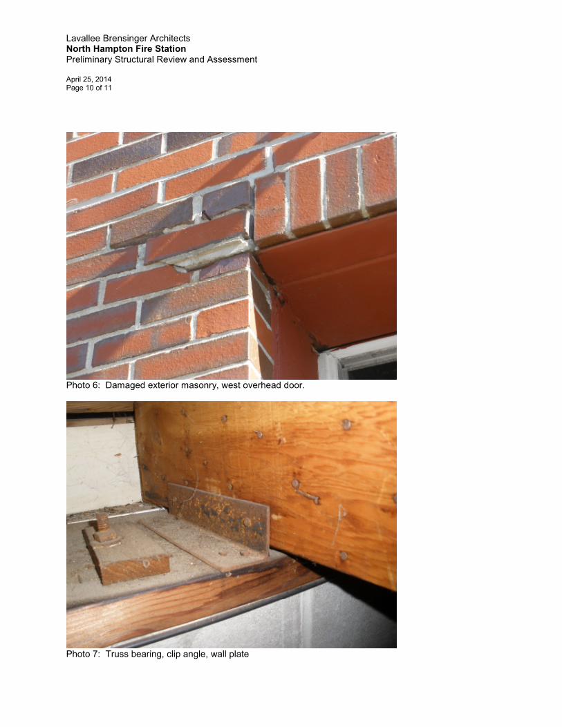
2. Anchorage at bearing points: The trusses are secured to the bearing plates at the tops of the masonry walls with an angle on one side of the truss. In my opinion, this connection is inadequate to resist the wind uplift loads found in the current Building Code.
3. Hose tower trusses: The hose tower extends through the main roof, interrupting the typical gable roof trusses. Mono-pitch trusses have been used on either side of the hose tower. The interior ends of these mono-pitch trusses bear upon steel beams on the east and west sides of the tower. The trusses do not appear to be secured to the steel beams, leaving them vulnerable to wind uplift loads. In addition, these trusses do not appear to have been custom-fabricated for this location. Rather, it appears that these trusses were field fabricated by cutting and modifying the 60’ clear span trusses used elsewhere in this roof structure. As a result, the trusses on the east side of the tower are not fully triangulated at their interior (tower) end. The absence of a web diagonal member extending directly from the interior bearing to the nearest top chord panel point negates any true “truss” action in that panel and requires that loads be transmitted to the interior bearing via flexural stresses in the top and bottom chords. Trusses are typically intended to carry primary loads as axial loads and are typically not designed and sized to transmit primary loads in flexure. I would expect that this condition has a significant adverse effect on the snow load capacity of the roof in this area. This is an observed condition that should be confirmed by quantitative analysis.
Masonry Issues Given the estimated date of construction, it is likely that the concrete masonry walls of the building are not grouted solid and do not contain steel reinforcing. FBRA recommends that this assertion be verified by field testing, involving scanning the walls with a rebar detector. The absence of any reinforcing steel in these walls would significantly degrade their performance in the event of a seismic event (see “Seismic Aspects” and “Code Issues” below). The south gable end wall of the building appears to be separating from the interior partition wall that separates the apparatus bay from the office area. This separation is of varying width and is

Lavallee Brensinger Architects North Hampton Fire Station Preliminary Structural Review and Assessment April 25, 2014 Page 4 of 11
approximately ¾” wide near the ceiling line. This condition appears to be due to an outward “lean” or rotation of the south gable end wall. Damaged, displaced, or “step-cracked” masonry was observed at the upper corners of two of the apparatus bay overhead doors. Specifically, this damage is visible at the east corner of the east door and the west corner of the west door. At the east door, this damage is likely related to the outward movement of this wall noted in the preceding paragraph. At the west door, the damage is more localized and was likely caused by a vehicular impact. Floor Slab A concrete topping has been applied over the original apparatus bay slab. This topping was observed to be cracked in several locations. Chief Cote noted that the topping appears to be delaminating in some areas. This condition should be investigated further by “sounding” the slab with a hammer, steel rod, or “chain drag” to determine the extents of this problem. This will require removing the apparatus from the building in order to conduct this testing. The slab surface at the apparatus bay doors has been patched with bituminous concrete, creating a high spot at each door. This is a tripping hazard and it may also present drainage issues. Seismic Aspects The details of the building structure are consistent with the reported 1960 vintage construction date. Accordingly, it is likely the building predates any building code requirements related to seismic design by about 10 to 15 years. The building is dependent on the perimeter exterior masonry walls acting as shear walls in order to transmit lateral loads (i.e., wind and seismic loads) to the foundation. However the south gable end wall has a limited capacity to act as a lateral load-resisting element due to the number, size and arrangement of the door and window openings in this wall. This situation leaves the building vulnerable to east-west lateral loads and particularly to seismic loads. As discussed above, the construction date makes it likely that the exterior walls are not reinforced (or that they contain horizontal joint reinforcement only). The absence of reinforcement would make the building more susceptible to damage in a seismic event. Radio Tower Viewed from the ground, the radio communications tower appears to be a Rohn type 25G tower. The mast is approximately 35 feet high, measured from the building roof. The tower has a single guying level and it has guy wires extending in three directions. Viewed in plan, the preferred arrangement of these guy wires would be 120 degrees between the wires. Given the position of this tower on the roof, the installed angle between guy wires appears to be greater than 120 degrees on the northerly side of the tower. All of the tower guy wires are secured to the building roof. The anchorages for the guy wires include a hooked bolt that penetrates the roofing and roof deck and hooks under a truss top chord (see photo). These anchorages appear to be inadequate and should be reviewed by a qualified antenna installation firm.

Lavallee Brensinger Architects North Hampton Fire Station Preliminary Structural Review and Assessment April 25, 2014 Page 5 of 11
The tower itself has three vertical legs. The two northerly legs are secured to the masonry of the hose tower. Those attachments appear adequate for resisting lateral wind loads on the tower. However they do not serve to support the vertical weight of the tower or to resist the downward thrust of the resulting from wind loads acting on the tower. Those vertical loads are transmitted to the plywood roof deck at the base of the tower via a bearing plate. No supplemental framing or reinforcement has been added beneath the roof deck to support the vertical loads imposed by this tower. Hose Tower The hose tower is no longer used due to safety concerns related to its ladder. The tower is comprised entirely of concrete masonry units, with a brick veneer above the roof line. No structural issues were observed. North Gable End Wall The Hose Tower roof drains via a scupper, resulting in water running down the north gable end wall of the building. This drainage has discolored the brick masonry and will eventually lead to premature degradation of that façade. Storage Mezzanine There are two pairs of small doors, located high on the wall that separates the apparatus bay from the personnel/office areas. These doors allow access to the space over the personnel/office area ceiling. Limited areas of the ceiling joists have had a plywood or board floor deck installed and those areas, creating a mezzanine floor that is now used for light storage. A ladder is required to gain access to these storage areas. The ceiling joists were noted to be 2x6 @ 16” on centers, with a span of 15 feet. This is an excessive span for a 2x6 and accordingly FBRA recommends this mezzanine storage area should be used only for storage of very light loads. Present Building Code Requirements pertaining to Structure for New Fire Department Facilities Present Building Code requirements for new construction would classify a Fire Station as an Occupancy IV facility, indicating an “essential facility”. The intent of this design classification is that the building remain in service during an emergency or following a natural disaster. This involves designing the facility for amplified wind, snow and seismic loads, relative to other building types. Since this is an existing building, it is presently code-compliant in a “grandfathered” status, and is therefore not required to meet the design load standards applicable to new construction.

Lavallee Brensinger Architects North Hampton Fire Station Preliminary Structural Review and Assessment April 25, 2014 Page 6 of 11
In evaluating the continued serviceability of this facility, the Town should recognize the vulnerabilities and inherent limitations of this building with regard to wind, snow and seismic loads, as outlined in this report. This report is intended to address structural conditions only. Architectural, mechanical and electrical evaluation of the facility is to be conducted by others. Photographs of several of the conditions noted in this report are attached. Very truly yours, FOLEY BUHL ROBERTS & ASSOCIATES, INC.
Richard E. Roberts, P.E. Vice President

Lavallee Brensinger Architects North Hampton Fire Station Preliminary Structural Review and Assessment April 25, 2014 Page 7 of 11
Photo 1: South Elevation
Photo 2: West Elevation, fire tower and antenna tower.

Lavallee Brensinger Architects North Hampton Fire Station Preliminary Structural Review and Assessment April 25, 2014 Page 8 of 11
Photo 3: Bowed truss web diagonals, no thru-truss bracing.
Photo 4: Radio antenna tower and hose tower.

Lavallee Brensinger Architects North Hampton Fire Station Preliminary Structural Review and Assessment April 25, 2014 Page 9 of 11
Photo 5: Antenna guy anchorage to truss top chord.
Lavallee Brensinger Architects North Hampton Fire Station Preliminary Structural Review and Assessment April 25, 2014 Page 10 of 11
Photo 6: Damaged exterior masonry, west overhead door.
Photo 7: Truss bearing, clip angle, wall plate

Lavallee Brensinger Architects North Hampton Fire Station Preliminary Structural Review and Assessment April 25, 2014 Page 11 of 11
Photo 8: separation of south gable end wall (at right) from intersecting interior wall (left).