APR + (Advanced Power Reactor Plus) Korea Hydro and ...
39
APR + (Advanced Power Reactor Plus) Korea Hydro and Nuclear Power Company, Republic of Korea Overview Full name Advanced Power Reactor Plus Acronym APR + Reactor type PWR Coolant Light Water Moderator Light Water Neutron Spectrum Thermal Neutrons Thermal Capacity 4290 MW(th) Electrical Capacity 1560 MW(e) gross 1505 MW(e) net Design Organization Korea Hydro and Nuclear Power Co. Last update 11-06-2013 1. Introduction The Advanced Power Reactor Plus (APR+), an improved nuclear power reactor with 1500MW electric power to succeed the Republic of Korea’s current Advanced Power Reactor 1400 (APR1400), has been developed as a two-loop evolutionary pressurized water reactor by adopting a number of advanced design features to further enhance safety, economics, and reliability. The Korean government and nuclear industry cooperatively launched the “Nuclear Technology Development Plan 2012 (Nu-Tech 2012 plan)” in December 2006. The goal of this plan is to enhance technical competitiveness in the global market and to have an intellectual property-free reactor design. The main project under the Nu-Tech 2012 plan is the development of APR+ standard design and related key technologies. The APR+ technology development project consists of three sub-projects: 1) the feasibility study for the APR+ development, 2) the key technology development for the APR+ design, and 3) the APR+ standard design development. The first sub-project, feasibility study for APR+ development, has been carried out for 2 years from August 2007 to July 2009. The major goals of this study are to identify top-tier requirements, to develop a conceptual design, and to evaluate safety, economics, and performance characteristics of the APR+ conceptual design. From this study, it is concluded that the APR+ design can be developed as a two loop evolutionary pressurized water reactor with a number of advanced design features to enhance safety and economics based on the APR1400 technology. For the economic enhancement, the APR+ reactor core power has been determined to be increased to 4,290 MWth which corresponds to a 1500MWe class nuclear power plant. Also, the plant design development has been performed so that several new construction technologies can be introduced in order to shorten the construction period. For the safety improvement, a number of advanced design features are introduced in the APR+ design such as the improved direct vessel injection (DVI+), advanced fluidic device (FD+), passive auxiliary feedwater system (PAFS), and four independent trains of safety systems, mechanically as well as electrically, based on N+2 design concept. As severe accident mitigation design features, the emergency reactor depressurization system (ERDS) for rapid depressurization during high pressure severe accident scenarios and the enhanced in-vessel retention through external reactor vessel cooling (IVR-ERVC) system are newly incorporated. Also, technical countermeasures against the
Transcript of APR + (Advanced Power Reactor Plus) Korea Hydro and ...
APR + (Advanced Power Reactor Plus)
Korea Hydro and Nuclear Power Company, Republic of Korea
Overview
Full name Advanced Power Reactor Plus
Acronym APR + Reactor type PWR
Coolant Light Water
Moderator Light Water Neutron Spectrum Thermal Neutrons
Thermal Capacity 4290 MW(th)
Electrical Capacity 1560 MW(e) gross
1505 MW(e) net Design Organization Korea Hydro and Nuclear Power Co.
Last update 11-06-2013
1. Introduction
The Advanced Power Reactor Plus (APR+), an improved nuclear power reactor with 1500MW
electric power to succeed the Republic of Korea’s current Advanced Power Reactor 1400
(APR1400), has been developed as a two-loop evolutionary pressurized water reactor by adopting a number of advanced design features to further enhance safety, economics, and reliability.
The Korean government and nuclear industry cooperatively launched the “Nuclear
Technology Development Plan 2012 (Nu-Tech 2012 plan)” in December 2006. The goal of this plan is to enhance technical competitiveness in the global market and to have an
intellectual property-free reactor design. The main project under the Nu-Tech 2012 plan is the
development of APR+ standard design and related key technologies. The APR+ technology
development project consists of three sub-projects: 1) the feasibility study for the APR+ development, 2) the key technology development for the APR+ design, and 3) the APR+ standard
design development.
The first sub-project, feasibility study for APR+ development, has been carried out for 2 years from August 2007 to July 2009. The major goals of this study are to identify top-tier requirements, to
develop a conceptual design, and to evaluate safety, economics, and performance characteristics of
the APR+ conceptual design. From this study, it is concluded that the APR+ design can be developed as a two loop evolutionary pressurized water reactor with a number of advanced design
features to enhance safety and economics based on the APR1400 technology. For the economic
enhancement, the APR+ reactor core power has been determined to be increased to 4,290 MWth
which corresponds to a 1500MWe class nuclear power plant. Also, the plant design development has been performed so that several new construction technologies can be introduced in order to shorten
the construction period.
For the safety improvement, a number of advanced design features are introduced in the APR+ design such as the improved direct vessel injection (DVI+), advanced fluidic device (FD+), passive
auxiliary feedwater system (PAFS), and four independent trains of safety systems, mechanically as
well as electrically, based on N+2 design concept. As severe accident mitigation design features, the emergency reactor depressurization system (ERDS) for rapid depressurization during high pressure
severe accident scenarios and the enhanced in-vessel retention through external reactor vessel
cooling (IVR-ERVC) system are newly incorporated. Also, technical countermeasures against the

unexpected beyond design basis natural disaster have been selected for incorporation into the APR+
standard design. The major design requirements for the safety and performance goals set for APR+ are listed in Table 1.
TABLE 1. APR+ DESIGN REQUIREMENTS FOR SAFETY AND PERFORMANCE GOALS
General Requirement Performance requirements and economic goals
Type and capacity : PWR, 1500 MWe
Plant lifetime : 60 years
Seismic design : SSE 0.3g
Safety goals : Core damage frequency < 1.0E-6/RY
Containment failure frequency < 1.0E-7/RY
Occup. radiation exposure < 1 man -Sv / RY
Plant availability : greater than 92%
Unplanned trips : less than 0.2 times per year
Refueling interval : 18 months or longer
Construction period : 36 months (N-th plant) from first concrete (F/C) to fuel loading (F/L)
Economic goal : ≥ 20% cost advantage over
fossil fueled power plants
The second sub-project, key technology development for the APR+ design, is intended to develop and demonstrate major advanced design features in order to support APR+ standard design
development focusing on six (6) technologies: 1) safety injection system optimization and
development including the improved Direct Vessel Injection (DVI+) and the advanced fluidic device (FD+), 2) passive auxiliary feedwater system (PAFS), 3) multiple severe accident mitigation system,
4) automatic load follow operation, 5) improved control element drive mechanism (CEDM), and 6)
combined modularization of components and structure. Finally, the third sub-project, APR+ standard
design development, launched in April 2009 aiming at acquiring the standard design approval from the Korean nuclear regulatory body by 2013.
The APR+ RCS configuration is the same as that of the APR1400 as shown in Figure 1. The APR+
standard design development is completed by incorporating the key technologies developed from the second sub-project, the state-of-the-art design features accepted globally and the design
improvements and lessons learned from design and construction of the APR1400. The first
APR1400 units are being built in the Republic of Korea as Shin-Kori Nuclear Power units 3 and 4
(SKN 3&4). Additionally the self-developed new reactor coolant pump (RCP) and man machine interface system (MMIS) technologies will be implemented in the APR+ design. Also, the reactor
core design and safety analyses are performed using the new specific code packages which are also
under development in parallel with the APR+ development. Finally, the increased reactor power up to 4,290 MWth will be accomplished by adding sixteen (16) fuel assemblies to the APR1400 reactor
core.

Figure 1. APR+ Reactor Coolant System Configuration
2. Description of the Nuclear Systems
2.1 Primary circuit and its main characteristics
The APR+ is characterized as a two-loop evolutionary PWR. The APR+ core thermal power is uprated to 4,290 MWth, which corresponds to a 1,500 MWe class nuclear power plant. This
power rating is 108% of the APR1400 core power and is considered to be the maximum
power output with a two-loop reactor coolant system (RCS) configuration while minimizing component size change. As shown in Figure 1, the APR+ RCS contains two primary coolant
loops, each of which consists of one 1.07-meter (42-inch) inside diameter (ID) hot leg, two
0.76-meter (30-inch) ID cold legs, one steam-generator (SG) and two reactor coolant pumps
(RCPs). One pressurizer (PZR) with heaters is connected to the hot leg of the RCS. The full power hot leg temperature of APR+ was increased from 323.9
oC (615
oF) of the APR1400 to
326.1oC (619
oF) to optimize the RCS design parameters. The total RCS flowrate is increased
to about 103% of the APR1400, which is optimized through the primary component sizing.
In the reactor pressure vessel (RPV) design, four direct vessel injection (DVI) lines are
connected to supply emergency core cooling water from the in-containment refuelling water
storage tank (IRWST). Level probes are added in the hot leg to monitor the water level during mid-loop operation. The RCS overpressure protection and reactor safety
depressurization functions are established by four (4) pilot-operated safety relief valves
(POSRVs) while the emergency reactor depressurization valves (ERDVs) provide rapid
depressurization function dedicated for severe accidents. On the secondary side of the SGs, two main steam lines are arranged on each SG, and each steam line has five non-isolable main
steam safety valves (MSSVs), one main steam atmospheric dump valve (MSADV), and two
main steam isolation valves (MSIVs). The APR+ design employs the passive auxiliary feedwater system (PAFS) that removes core decay heat and RCS residual heat through SGs to
establish and maintain the plant in a safe shutdown condition when the normal feedwater
supply is not available. The PAFS, which is intended to completely replace the conventional active auxiliary feedwater system, is one of the advanced passive safety features adopted in
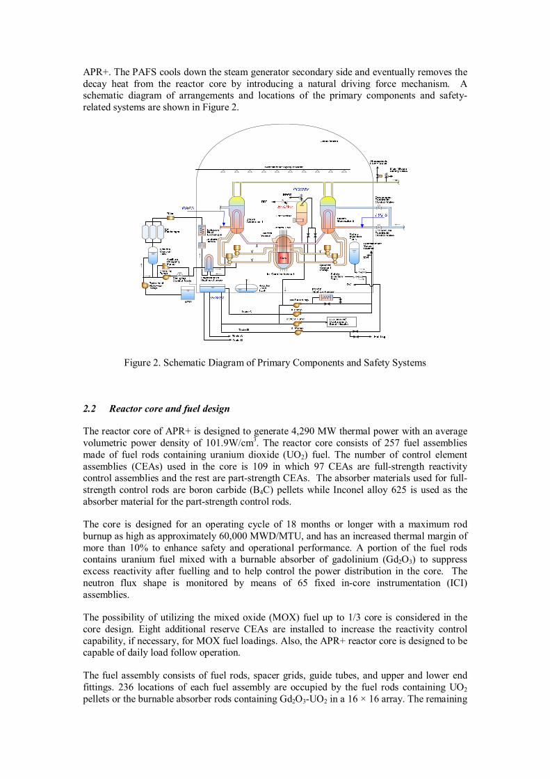
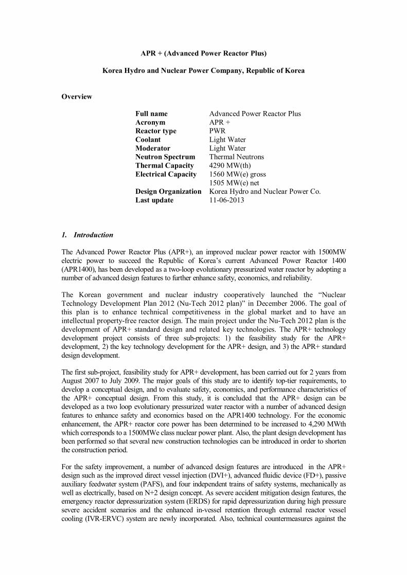
APR+. The PAFS cools down the steam generator secondary side and eventually removes the
decay heat from the reactor core by introducing a natural driving force mechanism. A schematic diagram of arrangements and locations of the primary components and safety-
related systems are shown in Figure 2.
Figure 2. Schematic Diagram of Primary Components and Safety Systems
2.2 Reactor core and fuel design
The reactor core of APR+ is designed to generate 4,290 MW thermal power with an average
volumetric power density of 101.9W/cm3. The reactor core consists of 257 fuel assemblies
made of fuel rods containing uranium dioxide (UO2) fuel. The number of control element
assemblies (CEAs) used in the core is 109 in which 97 CEAs are full-strength reactivity control assemblies and the rest are part-strength CEAs. The absorber materials used for full-
strength control rods are boron carbide (B4C) pellets while Inconel alloy 625 is used as the
absorber material for the part-strength control rods.
The core is designed for an operating cycle of 18 months or longer with a maximum rod
burnup as high as approximately 60,000 MWD/MTU, and has an increased thermal margin of
more than 10% to enhance safety and operational performance. A portion of the fuel rods contains uranium fuel mixed with a burnable absorber of gadolinium (Gd2O3) to suppress
excess reactivity after fuelling and to help control the power distribution in the core. The
neutron flux shape is monitored by means of 65 fixed in-core instrumentation (ICI)
assemblies.
The possibility of utilizing the mixed oxide (MOX) fuel up to 1/3 core is considered in the
core design. Eight additional reserve CEAs are installed to increase the reactivity control
capability, if necessary, for MOX fuel loadings. Also, the APR+ reactor core is designed to be capable of daily load follow operation.
The fuel assembly consists of fuel rods, spacer grids, guide tubes, and upper and lower end
fittings. 236 locations of each fuel assembly are occupied by the fuel rods containing UO2
pellets or the burnable absorber rods containing Gd2O3-UO2 in a 16 × 16 array. The remaining

locations are 4 CEA guide tubes and 1 in-core instrumentation guide tube for monitoring the
neutron flux shape in the core.
The HIPER16TM
fuel, which will be used for APR+, has the capability of a batch average discharge
burn-up as high as 65,000 MWD/MTU and has an increased overpower margin as compared to the
previous fuel design (PLUS7TM
). The HIPER16TM
mid-grid design has high through-grid dynamic
buckling strength for the enhanced seismic performance. The top nozzle has easy reconstitutability features and hold-down spring force was optimized to reduce the fuel assembly bow. The debris
filtering and capturing features are implemented in the bottom grid by combining the debris filtering
bottom grid and the long bottom end plug to reach the target of zero fuel failure. The bottom nozzle has a low pressure drop features with rectangular flow holes. The integrity of HIPER16
TM fuel has
been enhanced by increasing the fretting wear resistance and debris filtering efficiency. Also, the
safety of HIPER16TM
fuel has been enhanced by increasing the seismic performance which is related to the spacer grid crush strength and dynamic stiffness.
2.3 Fuel handling and transfer systems
The fuel handling system is designed for a safe and rapid handling and storage of fuel
assemblies from the receipt of fresh fuel to the shipment of spent fuel.
The major equipment of the system comprises the refuelling machine, the CEA change
platform, the fuel transfer system, the fresh fuel elevator, the CEA elevator and the spent fuel
handling machine. The refuelling machine is located in the containment building and moves fuel assemblies into and out of the reactor core and between the core and the fuel transfer
system. The spent fuel handling machine, located in the fuel building, carries fuel to and from
the fuel transfer system, the fresh fuel elevator, the spent fuel storage racks, and the spent fuel shipping cask areas.
2.4 Primary components
2.4.1 Reactor pressure vessel
The reactor pressure vessel is a vertically mounted cylindrical vessel with a hemispherical lower head welded to the vessel and a removable hemispherical upper closure head as shown
in Figure 3. The internal surfaces in contact with the reactor coolant are cladded with austenitic
stainless steel to prevent corrosion. The reactor vessel diameter of the APR+ is bigger than that of the APR1400 to accommodate additional fuel assemblies by about 0.3 m (1 ft). The reactor pressure
vessel contains internal structures, core support structures, fuel assemblies, control rod
assemblies, and control and instrumentation components.

Figure 3. Reactor Pressure Vessel and Internals
The structural integrity of the reactor pressure vessel is verified through a structural sizing and
fatigue evaluation, which calculates the stresses of the heads, shell and nozzles under thermal and pressure loads.
The direct vessel injection (DVI) nozzles are attached to the reactor vessel for the direct
emergency coolant injection as a part of the safety injection system. The location of DVI
nozzle is above the cold leg nozzles to avoid the interference with reactor vessel external nozzles and support structure.
The life time of the reactor pressure vessel is extended to 60 years by the use of low carbon
steel, which has lower contents of Cu, Ni, P, S, resulting in an increase of brittle fracture toughness. The inner surface of the reactor vessel is cladded with austenitic stainless steel or
Ni-Cr-Fe alloy. The reactor vessel is designed to have an end-of-life RTNDT of 21.1oC (70
oF).
The reactor vessel is basically manufactured with a vessel flange, a hemispherical bottom
head, and three shell sections of upper, intermediate and lower. The vessel flange is a forged ring with a machined ledge on the inside surface to support the core support barrel, which in
turn supports the reactor internals and the core. The three shell sections, the bottom head
forging and vessel flange forging are joined together by welding. Also, four inlet nozzle forgings, two outlet nozzle forgings, four DVI nozzle forgings, and sixty-one ICI nozzles are
also welded. The upper closure head is fabricated separately and is joined to the reactor vessel
by bolting. The dome and flange are welded together to form the upper closure head, on which the control element drive mechanism (CEDM) nozzles are welded.
2.4.2 Reactor internals

The reactor internals consist of the core support structures, which include the core support
barrel, upper guide structure barrel assembly and lower support structure, and the internal structures. The core support structures are designed to support and orient the reactor core fuel
assemblies and control element assemblies, and to direct the reactor coolant to the core. The
primary coolant flows in through the reactor vessel inlet nozzles from the reactor coolant
pump, passes through the annulus between the reactor vessel and core support barrel, through the reactor vessel bottom plenum and core, and finally flows out through the outlet nozzles of
the reactor vessel connected to the hot legs.
The core support barrel and the upper guide structure are supported at its upper flange from a ledge in the reactor vessel flange. The flange thickness is increased to sustain the enhanced
seismic requirements. All reactor internals are manufactured of austenitic stainless steel
except for the hold-down ring, which is made of high-tension stainless steel. The hold-down ring absorbs vibrations caused by the load to the axial direction of internal structures.
The upper guide structure, which consists of the fuel assembly alignment plate, control
element shroud tubes, the upper guide structure base plate, CEA shrouds, and an upper guide
structure support barrel, is removed from the core as a single unit during refuelling by means of special lifting rig.
2.4.3 Steam generators
The steam generator (SG) is a vertical inverse U-tube heat exchanger with an integral economizer, which operates with the RCS coolant in the tube side and the secondary coolant
in the shell side as shown in Figure 4. The basic design feature of the APR+ steam generator is the
same as that of the APR1400. The heat transfer area of the SG is increased to accommodate the uprated thermal power by increasing the height of U-tubes. The height is increased by about one (1)
foot as compared to that of the APR1400. Therefore, the upper shell diameter and the head dome
radius of the SG would increase by 10 inches and 5 inches, respectively. The SG vessel material is
changed from SA-508 Grade 1A to high strength alloy steel, SA-508 Grade 3 class 2, to reduce the total weight of the SG using the optimized thickness of the SG vessel.
The moisture separators and steam dryers on the shell side of the SG limit the moisture content of the
exit steam to less than 0.25 w/o during normal operation. To preclude uncontrolled steam releases and resultant uncontrolled cooldown of the RCS, the main steam isolation valves (MSIVs) are
designed as fail-close. Redundant MSIVs to meet the single failure criteria are provided in each main
steam line. The capacity of the spring-loaded main steam safety valves (MSSVs) is sufficient to limit
the maximum steam generator secondary side pressure in accordance with the requirements. The MSSVs discharge steam to the atmosphere outside the reactor containment building. The leak-
before-break concept is applied to the main steam lines to reduce the need for redundant supports of
the piping and, thus, the construction and maintenance costs will be reduced.
To improve the operability, the angle of nozzle in the hot leg side of the primary system is
modified to enhance the stability of mid-loop operation. The SG water level control system is
designed in such a way that the water level is controlled automatically over the full power operating range.
The economizer feedwater nozzle provides a passage of feedwater to the economizer, which
is installed to increase the thermal efficiency of the steam generator at the cold side, and
experiences a high temperature gradient. The feedwater nozzles are designed to endure the excessive thermal stress which causes an excessively large fatigue usage factor. The
downcomer feedwater nozzle attached in the upper shell of SG also provides small portion of
feedwater to the downcomer to facilitate internal recirculation flow. 10% of full power feedwater flow is provided to the downcomer feedwater nozzle and the remaining feedwater

to the economizer feedwater nozzle at a reactor power higher than 15%, below which all
feedwater is supplied to the donwncomer feedwater nozzle.
Figure 4. Steam Generator
2.4.4 Pressurizer
The pressurizer (PZR) is equipped with nozzles for sprays, surgeline, pilot-operated safety relief
valves (POSRVs), emergency reactor depressurization valves (ERDVs), and pressure and level
instrumentations. The RCS overpressure protection and manual safety depressurization functions are
established by four (4) POSRV assemblies while ERDVs provide a rapid depressurization function dedicated for severe accidents.
The volume of pressurizer (PZR) is 80.7 m3, being larger than the ratio of power increase
from the APR1400, which would reduce the potential causes of plant unavailability by more effectively accommodating overpressure transients as well as reactor coolant volume
shrinkage or swelling due to temperature/load changes.
2.4.5 Integrated head assembly (IHA)
APR+ adopts the integrated head assembly (IHA) to simplify structural configuration of the upper closure head region of the reactor vessel and to improve maintenance convenience as shown in
Figure 5. By adopting the IHA, the occupational exposure dose, component storage area and
overhaul duration are expected to be reduced significantly.
Upper Taps, 550.5"
NWL
0% NR, 400.5"
0% WR, 150.5"
Economizer
Economizer Feedwater Nozzle
Blowdown Nozzle
Evaporator
Downcomer
Downcomer Feddwater Nozzle
Recirculation Nozzle
Steam Dryer Drain
Steam Dryer
Centrifugal Separator
Tube Support Plate
Tube Bundle Shroud
Tubesheet
Nozzle Dam
Steam Outlet Nozzle
Secondary Manway
Center Support Cylinder
Handhole

The newly developed control element drive mechanism (CEDM) is implemented in the APR+
design. It will be able to operate for a longer period of time and to allow the CEDM motor and coil assembly to be suitable for the load follow operation. The CEDM power cable is installed at the
upper part of the coil housing. This arrangement can simplify the CEDM coil assembly and enhance
the coil cooling performance. The reduced cooling air flow will also contribute to the simplification
of the RV head area system related to the CEDM because the cooling fan size and seismic loads can be reduced.
Figure 5. Integral Head Assembly
2.4.6 Reactor coolant pumps
The newly developed RCP is implemented in the APR+ design. This RCP is the same model as, but larger in size than that that for the Shin-Ulchin Nuclear Power Plant Units 1 and 2 (SUN 1&2), the
first construction plant utilizing new RCPs. It has several improved design features as compared to
the RCP for APR1400 as shown in Figure 6. For example, the use of standstill seal minimizes the RCS water leakage via the shaft seal under simultaneous loss of seal injection water and component
cooling water after and/or during the station blackout. The spool piece, which connects the pump
shaft to the thrust bearing shaft, provides enough space to replace the mechanical seal without lifting
the thrust bearing assembly.
To find an optimal hydraulic design that satisfies all of the hydraulic performance requirements of
APR+ RCP, an RCP model test has been performed. The APR+ RCP model test data are the
reference for guaranteeing performance of prototype RCP. Another purpose of the model test is to acquire the 4-quadrant curve of the accepted hydraulic model. The 4-quardrant curve is the
performance curve for all the possible pump flow and rotation conditions. The 4-quadrant curve is
used for input data for safety analysis.

Figure 6. SKN 3&4 RCP(left) vs. APR+ RCP(right)
2.4.7 RCS Piping
Since the pipe whip restraint and the support of the jet impingement shield in the piping
system of earlier plants are expensive to build and maintain and could lead to a potential
degradation of plant safety, the Leak-Before-Break (LBB) principle is adopted for the piping system of APR+. The LBB principle is applied to the main coolant lines, surge lines, and
pipes in the shutdown cooling system and the safety injection system. The application of
LBB reduces the redundant supports of the pipe in the NSSS pipe system since the dynamic
effects of postulated ruptures in the piping system can be eliminated from the design basis. Therefore, the cost of design, construction and maintenance is reduced.
2.5 Reactor auxiliary systems
2.5.1 Chemical and volume control system (CVCS)
The CVCS of the APR+ is not required to perform any safety functions such as safe shutdown and
accident mitigation. This system is basically for the normal day-to-day operation of the plant. The
components related to charging and letdown functions, however, are designed as a safety grade and reinforced to assure the reliability for normal and transient conditions. Two centrifugal charging
pumps and a flow control valve provide required charging flow. For normal operation, only one
charging pump is used to supply the required minimum flow of 12.6 kg/s.
Pressure reduction of the letdown flow from the reactor coolant system occurs at the letdown orifice and the letdown control valve. Then the letdown flow passes through the regenerative and letdown
heat exchangers, where the temperature reduction takes place. Following pressure and temperature
reduction, the flow passes through a purification process at the filters and ion exchangers. After passing through the purification process, the letdown flow is diverted into the volume control tank
(VCT) which is designed to provide a reservoir of reactor coolant for the charging pumps and for the
dedicated seal injection pumps for the reactor coolant pumps.
2.5.2 Component cooling water system

The component cooling water system (CCWS) is a closed loop cooling system that, in conjunction
with the Essential Service Water System (ESWS) and Ultimate Heat Sink (UHS), removes heat generated from the plant’s essential and non-essential components connected to the CCWS. Heat
transferred by these components to the CCWS is rejected to the ESWS via the component cooling
water heat exchangers.
The CCWS consists of four separate, independent, redundant, safety related trains to meet N+2 design concept. Each train of the CCWS is capable of supporting 100 % of the cooling functions
required for a safe reactor shutdown. Each train of the CCWS includes two CCW heat exchangers, a
CCW surge tank, one CCW pump, a CCW chemical addition tank, a CCW radiation monitor, piping, valves, controls, and instrumentation.
2.5.3 Reactor coolant gas vent system (RCGVS)
The RCGVS is a part of the safety depressurization and vent system (SDVS). The reactor coolant gas vent valves are mounted at the top of the pressurizer and reactor vessel head. The size of the
vent line has sufficient capacity to vent one-half of the RCS volume in one hour assuming a single
failure.
2.5.4 Steam generator blowdown system
The functions of the SG blowdown system are to control SG secondary side water chemistry and to
remove sludge from the SG tube support plates. One flash tank can accommodate normal and high
capacity blowdown flow rates. To remove dynamic loading due to two-phase flow, the flash tank for blowdown is located in the auxiliary building near the containment. Bypass lines to the
condensers are installed to overcome unavailability of the flash tank or the processing system.
2.5.5 Primary sampling system
The primary sampling system is designed to collect and deliver representative samples of liquids and
gases in various process systems to the sample station for chemical and radiological analysis. The
system permits sampling during normal operation, cooldown and post-accident modes without
requiring access to the containment. Remote samples can be taken from the fluids in high radiation areas without requiring access to these areas.
2.6 Operating Modes
The APR+ is designed to be used for various operating modes not only for the base load full power operation but also for a part load operation such as the load follow operation. A standard 100-50-
100% daily load following operation and frequency control operation have been considered in the
reactor core design as well as in the plant control systems.
In addition, various load maneuvering capabilities are considered in the design such as up to 10% step change in load, +/- 5%/min ramp load changes. Also, it has the house load operation capability
during a sudden loss of load up to 100% (full load rejection) in which plant control systems
automatically control the plant at 3~5% power level without causing any reactor trips or safety system actuations.
In case of turbine generator trip from any power level including full power, the APR+ prevents
reactor trip and maintains reactor power at reduced level using reactor power cutback system (RPCS) and other control systems. This feature shortens outage time to return to power operation
after a problem shooting and enhances plant safety by preventing unnecessary reactor trips. Also, the
APR+ control system automatically controls plant parameters and prevents reactor trip during a loss
of one or two operating main feedwater pumps event occurring at 100% power operation with 3 main feedwater pumps in service.

The APR+ design has an improved load following operation capability with several design changes
as compared to the APR1400 in which the reactor power is automatically controlled by the Reactor Regulating System (RRS) while the core power distribution is manually controlled by the operator.
However, a new control concept, Model Predictive Controller (MPC), has been adopted in the
APR+ for the automatic control of the reactor power as well as the core power distribution. Also the
operator-supporting system for the control of boron concentrations, additional monitoring systems for reactor core and control rods, and the constant T-avg operation program are also introduced. For
the constant T-avg operation, the coolant average temperature is maintained constant above 75%
power level, which reduces reactivity control demand during power reduction and, hence, control rod usage. The RCS temperature program as a function of power for the load following operation is
shown in Figure 7.
The newly developed control element drive mechanism (CEDM) is also be implemented in the APR+ design in order to operate the CEDM motor and coil assembly for a longer period of time for
load follow operation. The heat generation and heat transfer coefficient of the CEDM coils are
improved to reduce the cooling air flow rate, which will also contribute to the simplification of the
integrated head assembly (IHA) since the size of the CEDM cooling fan and related seismic loads can be reduced.
Figure 7. RCS Temperature Program
2.7 Fuel Cycle and Fuel Options
The APR+ is a typical PWR plant using slightly enriched uranium and, hence, is not designed as a
breeder or a high-converter reactor. However, the reactor core and other related systems are designed
to use MOX fuel up to 1/3 of core. The spent fuel treatment plan is beyond the plant design scope.
3. Description of Safety Concept
3.1 Safety requirements and design philosophy
Safety is a requirement of paramount importance for nuclear power. One of the APR+ development
policies is to increase the level of safety significantly. Safety and economics in nuclear power plants
are not counteracting each other but can move in the same direction since the enhancement of safety
540
560
580
600
620
640
0 25 50 75 100
Percent Power
React
or C
oola
nt T
em
per
atu
re,
deg.
F
T cold
T hot
T average

will also yield an improved protection of the owner investment. Therefore, safety has been given top
priority in developing the new design. To implement this policy, in addition to the plant being designed in accordance with the established licensing design basis to meet the licensing rules, the
APR+ was designed with an additional safety margin in order to improve the protection of the public
health as well as the owner investment.
In order to implement this safety objective, quantitative safety goals were established:
• The total Core Damage Frequency (CDF) shall not exceed 10-6/RY for internal initiating
events and 10-7/RY for a single event.
• The containment failure frequency shall be less than 10-7/RY.
• The whole body dose at the site boundary shall not exceed 0.01 Sv (1 rem) for 24 hours after
initiation of core damage with a containment failure.
To achieve above quantitative goals, the defense-in-depth concept remains as a fundamental principle of safety requiring a balance between accident prevention and mitigation. With respect to
accident prevention, the increased design margin and system simplification represent a major design
improvement and the consideration of accident mitigation call for the incorporation of design features to cope with severe accidents as well as design basis accidents.
In addition to the public safety, a concept of investment protection is implemented in the APR+
design. An example of design requirement that aims at investment protection is the stipulation that a
small break loss-of-coolant-accident (LOCA) with a break size smaller than 150 mm in diameter should allow the continued use of the reactor with its fuel inventory after the repair of the ruptured
pipe and/or other damages in the reactor coolant system.
The enhanced margin could benefit the operability and availability of the nuclear power plants. For example, the margin can alleviate transients, thereby avoiding unexpected trips, and be used for later
system modification or adaptation of new regulatory restriction. A few examples of the design
requirements set according to this philosophy are the requested core thermal margin of more than 10%, sufficient system capacity for the prolonged operator response time on the transient events, and
station blackout coping time.
To enhance the safety, reliability and availability, the APR+ safety related systems are designed to
perform their functions even though an individual component in any system fails to operate (single failure concern) and any component affecting the safety function is simultaneously inoperable due to
repair or maintenance. This design concept is called N+2 design philosophy implemented in the
latest advanced reactors. This N+2 design concept will enhance the plant safety, make the on-line maintenance (OLM) possible, and reduce the planned overhaul period.
3.2 Safety systems and features (active, passive and inherent)
The safety systems and features of the APR+ are designed to be a hybrid system in which active and passive systems perform necessary safety functions. The major safety systems are the safety
injection system, safety depressurization and vent system, in-containment refuelling water storage
system, shutdown cooling system, passive auxiliary feedwater supply system, and containment spray system.
The major design characteristics of the APR+ safety systems are as follows:

• Improved reliability of the safety injection system (SIS) through mechanically and electrically
independent four (4) train design
• Simplified operation of the SIS by merging the high pressure injection, low pressure injection,
and re-circulation modes into one injection mode
• Lowered susceptibility of IRWST against external hazards by locating RWST inside the
containment
• Enhanced plant safety by adopting the advanced features such as the FD+ in safety injection
tank (SIT), the IRWST, and the DVI+ in SIS
• Improved reliability of the containment spray system (CSS) through designing the CSS and
shutdown cooling system (SCS) in common
• Passive decay heat removal capability using PAFS which completely replaces the
conventional active auxiliary feedwater system
3.2.1 Safety injection system (SIS)
The safety injection system for the APR+ is designed with mechanically and electrically independent 4 trains based on N+2 design philosophy as shown in Figure 8. Each train has
100 percent capacity required to mitigate the design basis accident except for the large break
LOCA (LBLOCA). Each train has one active safety injection pump (SIP) and one passive SIT equipped with the fluidic device. The safety injection pumps and electrically actuated
valves are capable of being powered from the plant's normal power sources as well as the
emergency power sources such as Emergency Diesel Generators (EDGs). Power connections
are through four (4) independent power channels so that, in the event of a LOCA in conjunction with the loss of normal power and a single failure in the emergency electrical
power supply coincident with simultaneous inoperable condition due to OLM, the flow from
at least two (2) SIS trains is available for core protection. Each train has an independent flow path from the IRWST to the DVI nozzle attached in the upper part of the reactor vessel.
To satisfy the LOCA performance requirements, each train provides 50% of the minimum injection flow rate for breaks larger than the size of a direct vessel injection line. For breaks equal to or
smaller than the size of a direct vessel injection line, each train has 100% of the required capacity.
The low pressure injection pumps with common header installed in the conventional design are
eliminated, and the functions for safety injection and shutdown cooling are separated.
By adopting the passive flow regulator, fluidic device (FD), in the SIT and the IRWST system, the
current operation modes of high pressure injection, low pressure injection, and re-circulation are
merged into only one operation mode in case of LOCA. Accordingly, the low pressure pumps are eliminated from the SIS and the water for the safety injection is taken from the IRWST only.
The core cooling water is designed to be injected directly into the reactor vessel so that the
possibility of the spill of the injected water through the broken cold leg is eliminated. For this purpose, four safety injection lines are connected directly to the DVI nozzles located above the hot
and cold legs on the upper portion of the reactor vessel.

Figure 8. Four (4) Train Safety Injection System Configuration
3.2.2 Fluidic device (FD)
The driving mechanism of passive flow regulator installed in the SIT, which is called the fluidic device (FD), is a vortex flow resistance. The FD installed in the SIT enables effective use of SIT
water inventory for an extended period of time by delaying the SIT empty time so that the low
pressure safety injection pump is eliminated.
The FD provides a high discharge flow rate, when the SIT starts to inject, which is required during the refill phase of LBLOCA. When the refill phase is terminated, the discharge flow rate drops
sharply but is still large enough to remove any heat decay during the reflood phase. Because of the
strong vortex motion in the FD, the pressure loss coefficient of the low flow rate period is almost ten times higher than that of the high flow rate period.
An advanced fluidic device (FD+) as shown in Figure 9 is developed in order to reduce the
possibility of N2 gas ingestion during water discharge and to effectively utilize water volume
occupied below the FD.
Figure 9. Advanced Fluidic Device (DVI+) in SIT

3.2.3 ECC Core Barrel Duct (ECBD)
In case of the cold-leg break LOCA, a part of emergency core cooling (ECC) water which is injected through the direct vessel injection (DVI) nozzle can be swept out through the break in the cold leg
due to a massive steam discharge flow before it reaches bottom of the reactor vessel. The bypass of
ECC water reduces the cooling and inventory makeup of core. To minimize the bypass of ECC
injection water in the RV downcomer during the LOCA, 4 ECC Core Barrel Ducts (ECBDs) are installed vertically on the outer surface of the core support barrel at the corresponding position for
each DVI nozzle as shown in Figure 10. That is called the improved DVI (DVI+) design concept.
ECBD is a trapezoid duct attached on the outer wall of the core support barrel and has a circular inlet opening on upper part of the duct wall and a venting port at lower end. The inlet opening faces DVI
nozzle and venting port is open to downcomer.
The ECBDs are introduced to minimize the steam-water interaction in the downcomer annulus and provide a separate downward flow path of injected ECC water preventing it from being swept out
through the broken cold leg. The aspect of mechanical integrity and interference in assembling
process were also considered in developing the design. Various separate effect tests such as DVI+
ECC bypass Performance Test, Duct and Core Barrel Vibration Test, and Full Scale DVI Duct Injection Test were performed to evaluate the performance of the new design concept. The
experiments on ECC bypass with ECBD design showed that the ECBD practically prevents the
interaction between the ECC water and steam discharge, and that the bypass rate is much lower than that of previous design without ECBD.
Figure 10. DVI+ Layout and ECBD Location
3.2.4 In-containment refuelling water storage tank (IRWST)
The in-containment refuelling water storage tank is located inside the containment, and the arrange-
ment is made in such a way that the break flow as well as the injected core cooling water can return to the IRWST. It consists of an annular cylindrical tank along the containment wall at low elevation,
a holdup volume tank (HVT), and four inside sumps. The susceptibility of the current refuelling
water storage tank to external hazard is eliminated by locating it inside the containment. The IRWST provides the functions of the normal refuelling water storage, the containment sump as well
as a single source of water for the safety injection, shutdown cooling, and containment spray pumps.
The IRWST is also used as a heat sink to condense the steam discharged from the relief valves on
the pressurizer in case of the rapid depressurization of the RCS to prevent high pressure core melt ejection or to enable feed and bleed operation during the total loss of feedwater event. Moreover, it

provides the function of coolant supply to the external reactor vessel cooling system (ERVCS) and
the cavity flooding system (CFS) in case of a severe accident to retain the molten core inside reactor vessel and, if vessel breaks, to cool the molten core in the reactor cavity, respectively. The volume of
the IRWST is 2,623.29 m3 (696,000 gal). This capacity is sufficient for flooding the refuelling
cavity during normal refueling operations. It also covers the necessary water volume to flood the
HVT and the reactor cavity for the external reactor vessel cooling operation during severe accidents.
3.2.5 Shutdown cooling system (SCS)
The shutdown cooling system (SCS) is a safety-related system that is used in conjunction with the
main steam and main or auxiliary feedwater system to reduce the RCS temperature in post shutdown periods from the hot shutdown operating temperature to the refueling temperature. After initial heat
rejection through the SGs to the condenser or atmosphere, the SCS is put into operation at 176.7 ℃
and 31.6 kg/cm2A. The SCS and the containment spray system (CSS) are shared with common 4
trains, mechanically and electrically separated, based on N+2 design philosophy. Each train has 100
percent capacity required for safety function and consists of its own pump, heat exchanger, piping
and valves as shown in Figure 11.
The SCS and CSS have a different inlet and outlet configuration for their own function even though
they share common trains. For example, the SCS normal operation flow path is lined up from two (2)
hot legs to four (4) DVI nozzles. The normal CSS flow path is lined up from IRWST suction nozzles
to containment spray nozzles. The common train and a different inlet/outlet flow path of SCS/CSS will be adequately aligned through an automatic actuation signal or an manual operator action. This
common 4 train SCS/CSS design concept is expected to increase the system reliability and enable
on-power maintenance.
Figure 11. Schematic Diagram of SCS/CSS in the APR+
3.2.6 Passive Auxiliary Feedwater System
The Passive Auxiliary Feedwater System (PAFS) is one of the passive safety features adopted in the APR+ design and replaces the conventional active auxiliary feedwater system of the APR1400 by
introducing a natural driving force mechanism. It has a function of removing the decay heat and the

residual heat. The PAFS is composed of four independent trains to satisfy the single failure criterion
as shown in Figure 12. Two Passive Condensation Heat Exchanger (PCHX) bundles are installed inside the Passive Condensation Cooling water Tank (PCCT). The PAFS is designed to have a
capability of operating without AC power for a minimum of 8 hours to ensure a subsequent RCS
cooldown for 8 hours to the shutdown cooling entry condition even though the cooldown starts in 5
minutes after the reactor shutdown.
The steam generated in the steam generator is delivered to the PCHX and condenses in the heat
exchanger tubes. When the normally closed, DC powered isolation valve is open by an automatic or
a manual signal, the condensate flows down to the economizer feedwter nozzle of the steam generator by the gravitational force because the PCHX is located at high elevation. The PCCT
provides the heat sink for the PCHX. The heat addition from the PCHX initially increases the water
temperature. As condensation continues, the PCCT water reaches saturation temperature and then begins to boil. The steam generated in the PCCT is discharged to the atmosphere. Therefore, the core
decay heat is released by a natural circulation flow between the SG secondary side and the PCHX
that is immerged in the PCCT water.
Figure 12. Passive Auxiliary Feedwater System
3.2.7 Safety depressurization and vent system (SDVS)
The SDVS is a dedicated safety system designed to provide a safety grade means to depressurize and
vent the RCS in the event that pressurizer spray is unavailable during plant cooldown to the cold shutdown condition. Also, the SDVS is designed to rapidly depressurize the RCS to initiate the feed
and bleed operation of plant cooldown subsequent to a total loss of feed-water event. The SDVS
consists of 4 Pilot Operated Safety Relief Valves (POSRVs) and the RCGVS described in Section
2.5.3. This system establishes a flow path from the pressurizer steam space to the IRWST.
3.2.8 Containment spray system (CSS)

The CSS consists of four trains and its pump takes suction from the IRWST. The CSS is designed to
reduce the containment temperature and pressure during the accidents occurred in the containment and to remove fission products from the containment atmosphere following a loss of coolant
accident. The CSS is designed to be interconnected with the Shutdown Cooling System (SCS),
which shares the SC/CS pumps, SC/CS heat exchangers and SC/CS pump mini-flow heat
exchangers of the Shutdown Cooling (SC) System (see Figure 11). This design provides higher reliability of the CSS as compared to the conventional plant.
3.3 Experimental test for validation of new design features
The APR+ adopted new safety features such as the Passive Auxiliary Feedwater System (PAFS), the Emergency Core Cooling (ECC) Core Barrel Ducts (ECBDs), and the long life Control Element
Drive Mechanism (CEDM). To verify these new features, associated performance verification tests
were conducted separately. In addition to these separate effect tests, an integral effect test was also performed using ATLAS, Advanced Thermal Hydraulic Test Loop for Accident Simulation at the
Korea Atomic Energy Research Institute (KAERI) test facility for major design basis accidents
including large break LOCA for the APR+.
The ATLAS is an integral effect test facility which is designed from the viewpoints of both a global and local scaling based on the three-level scaling methodology. To verify the integrated effect on
safety of the APR+ new design features, a series of tests has been performed with ATLAS. These
tests include the reflood phase of the LBLOCA, small-break LOCA scenarios including the DVI line breaks, steam generator tube ruptures, main steam line breaks, and mid-loop operation.
In order to confirm the cooling and operation performance of the PAFS design, a separate effect test
and an integral effect test were carried out in the PAFS Condensing heat removal Assessment Loop (PASCAL) and ATLAS-Passive Auxiliary Feedwater System (ATLAS-PAFS) test facilities which
are designed with the volumetric scaling methodology and use steam and water as test fluids. It was
verified from these tests that the PAFS performance satisfies the standard design requirement of the
APR+.
In order to evaluate the Emergency Core Coolant (ECC) bypass during the reflood phase of a
postulated LBLOCA and to assess the contribution of 4 train SIS to safety enhancement, the
performance of SIS was examined by using a 1/5-scale full-core and full-scale 1-DVI test facilities. These experiments showed that the ECBD practically prevents the interaction between the ECC
water and steam discharge, and the bypass rate is much lower than that of the previous design
without ECBD.
The control element drive mechanism (CEDM) performance tests for the APR+ were carried out under the reactor operating condition. The performance test consists of a drop test, scram test,
accelerated life test and others. The maximum CEA drop time to 90% insertion was 2.9 seconds
which meets the 4.0 second drop time assumed in the safety analysis. The APR+ CEDM has a plan to perform the accelerated life test to over 200,000 feet travel length.
3.4 Severe accidents (beyond design basis accidents)
In the APR+ design, severe accidents are addressed as follows:
• For phenomena likely to cause early containment failure, for instance, within 24 hours
after accidents, mitigation systems shall be provided or the design should address the
phenomena although the probability for such accidents is low.

• For phenomena which potentially lead to late containment failure if not properly
mitigated, the mitigation system or design measures should be considered in conjunction
with the probabilistic safety goal and cost for incorporating such features to address the phenomena.
This approach is to enhance the effectiveness of investment on safety by avoiding undue over-invest-
ment on highly improbable accidents. Also, a realistic assessment is recommended for severe
accident analyses.
The facilities to mitigate severe accidents are designed to meet the procedural requirements and
criteria of the U.S.NRC regulations, including the Three Mile Island (TMI) requirements for new
plants as reflected in 10 CFR 50.34 (f) and SECY-93-087. As shown in Figure 13, the severe accident management systems designed in the APR+ consists of (1) large dry pre-stressed concrete
containment, (2) cavity flooding system (CFS), Hydrogen Mitigation System (HMS) to prevent
containment hydrogen concentrations from reaching detonation levels, (4) emergency reactor depressurization system (ERDS), (5) large reactor cavity designed for retention and cooling of core
debris, (6) emergency containment spray backup system (ECSBS), and (7) containment filtered vent
system (CFVS).
Figure 13. Severe Accident Management System
3.4.1 Large dry pre-stressed concrete containment
The containment, including all its penetrations, is a low leakage cylindrical concrete shell with an
interior steel liner which is designed to limit the release of radioactive material to within the requirements of 10 CFR 50.34. The cylindrical containment is 46.63 m (153 feet) in diameter and is
constructed of pre-stressed concrete with 1.37 m (4.5 feet) thick wall and 1.22 m (4 feet) thick dome.

The containment provides a net free normal volume of 96,277 m3 (3.40 x 10
6 ft
3) with its internal
structures arranged in a manner to (1) protect the inside of containment from missile threats, (2) promote mixing throughout the containment atmosphere, and (3) accommodate condensable and
non-condensable gas releases from design basis and severe accidents.
3.4.2 Cavity flooding system (CFS)
The function of the cavity flooding system (CFS) is to provide a means of flooding the reactor cavity during a severe accident for the purpose of cooling any core debris in the reactor cavity and
scrubbing fission product releases to the containment atmosphere. When activated, water delivery
from the IRWST to the reactor cavity is accomplished by means of active design attributes. The CFS is designed to provide a continuous supply of water to quench any core debris.
The CFS is designed to make use of available inside containment water sources in the IRWST and
holdup volume tank (HVT). The CFS consist of four connection piping between IRWST and HVT, and the reactor cavity which are two 355.6 mm (14 inch) diameter HVT spillways, two 304.8 mm
(12 inch) diameter reactor cavity spillways, their associated valves, and power supplies. The CFS
uses water from the IRWST and directs it to the reactor cavity through HVT.
3.4.3 Hydrogen mitigation system (HMS)
During a degraded core accident, hydrogen is produced at a greater rate than that of the design basis
LOCA. The hydrogen mitigation system (HMS) is designed to accommodate hydrogen production
from 100 % metal-water reaction and limit the average hydrogen concentration in containment to the 10
v/o in accordance with requirements for degraded core accidents. These limits are imposed to
preclude detonations in containment that might jeopardize containment integrity or damage essential
equipment.
The HMS consists of passive autocatalytic re-combiners (PARs) and igniters. The PARs are
effective for accident sequences in which mild or slow hydrogen release rates are expected, and are
provided all over the containment. The igniters supplement PARs for accidents of very low
probability where rapid release rates of hydrogen are expected. Igniters are placed near source locations to promote the combustion of hydrogen in a controlled manner such that the containment
integrity is maintained.
3.4.4 Emergency Reactor Depressurization System (ERDS)
The emergency reactor depressurization system is a dedicated system specifically designed to serve
accident and serves an important role in severe accident mitigation. In the event of a high pressure
meltdown scenario, the ERDS can be used to depressurize the RCS to ensure that a high pressure
melt ejection (HPME) does not occur, thereby this minimizes the potential for direct containment heating (DCH) following a reactor vessel branch.
3.4.5 Large reactor cavity
The reactor cavity is configured to promote retention of, and heat removal from, the postulated core
debris during a severe accident, thus, serving several functions in accident mitigation. Corium
retention in the core debris chamber virtually eliminates the potential for significant DCH induced containment loadings. The large cavity floor area allows the core debris to flow and spread out,
which enhances the ability to cool it within the reactor cavity region.
3.4.6 Emergency Containment Spray Backup System (ECSBS)

The Emergency Containment Spray Backup System (ECSBS) is used as an alternative means of
providing containment spray in the event of a beyond DBA in which all SC/CS pumps and/or the IRWST are unavailable. It is assumed to be placed in service 24 hours after a severe accident to
prevent a catastrophic failure of the containment. The emergency containment spray flow path is
from external water sources (the reactor makeup water tank, demineralized water storage tank, fresh
water tank, or the raw water tank), through the fire protection system line via the diesel driven fire pump, to the ECSBS line emergency connection located at ground level near the auxiliary building.
The fire protection system line outlet is connected to the fire truck pumper inlet and the water flow
circuit is completed when the fire truck pumper outlet is connected to the ECSBS emergency connection.
3.4.7 Containment Filtered Vent System (CFVS)
During a severe accident, generation of large amounts of steam or non-condensible gas causes over-pressurization of the containment atmosphere. For preventing this over-pressurization, a containment
penetration is exclusively assigned in conjunction with the Containment Filtered Vent System
(CFVS). The penetration should be capable of ventilation in case of a severe accident. By reserving
the big penetration as the dedicated penetration for CFVS, the requirement of 10 CFR 50.34(f) is to be met as much as possible. The penetration with 16 inch diameter sleeve size, a big spare
penetration on containment wall, is large enough for proper depressurization of the containment
atmosphere.
3.5 Seismic Design
In order to increase the resistibility of the buildings and the structures against earthquake, the
buildings and the structures are designed with applying the Safe Shutdown Earthquake (SSE) of 0.3g as a Design Basis Earthquake (DBE). And the seismic input motion enforced in the high frequency
range is applied to envelope the design ground response spectrum of Reg. Guide 1.60 standard
spectrum. In the meanwhile, according to 10 CFR 50 Appendix S, the seismic analysis considering
the Operating Base Earthquake (OBE) for the operation condition is eliminated.
Since the seismic evaluation is performed including the effect of the soil-structure interaction on the
soil sites, the APR+ plant can be constructed not only on the rock sites but on the soil ones.
3.6 Aircraft Impact Assessment (AIA)
New plant designs that are to be constructed and operated in the Republic of Korea consider
the effects of impact from large commercial aircraft under the 10 CFR 50.150. The Korea
licensing body has stipulated that the Aircraft Impact Assessments (AIA) of the APR+ plant
can be performed consistent with the guidance and methodology provided in Nuclear Energy Institute Report NEI 07-13, which has been accepted by the United States Nuclear Regulatory
Commission (U.S.NRC) in Regulator Guide 1.217.
The missile-target interaction analyses using a large commercial aircraft model are performed to evaluate structural integrity and shock vibration effect etc., and the design enhancements are carried
out to prevent internal damage. The strengthened exterior walls of the Reactor Containment
Building (RCB) and Auxiliary Building (AB) in the APR+ plant are sufficient to fully resist the impact loading and prevent airplane wreckage and fuel from penetrating into the building.
4. Proliferation resistance
Normal fuel manufactured for use in the water cooled reactors is low-enriched uranium (LEU, < 5% U-235) before irradiation. It is not possible to use this material as a weapon. Technically, the
plutonium that arises from today’s high burnup fuel should be undesirable as weapons material,
since the Pu-240 content is in excess of 25%. Also, the discharged fuel assemblies are far too radioactive to be accessible for potential diversion, and when held in shielded casks, far too heavy
for normal transport. In addition, plutonium is chemically very toxic, so remote handling is
necessary in a reprocessing factory.
5. Safety and Security (physical protection)
The APR+ design and plant layout considered safety and security in various ways in which the
design and configuration inherently protects the plant against human induced malevolent external impacts and insider action. The physical security system is designed in accordance with the
applicable regulations and is expected to provide protection against malevolent acts of sabotage with
high assurance.
The main design features for the APR+ safety and security are as follows:
• Thick concrete walls for exterior and a large number of interior walls protect those
equipments important to safety and provide a significant deterrent to penetration. The
Auxiliary Building is physically separated in 4 quadrants, which provides adequate physical
separation and barrier.
• The entry control point to the plant is centralized with security facilities and located in the
compound building only for both units for the twin unit plants.
• A robust vehicle barrier system that is located at a safe standoff distance.
• Fencing is employed to establish a perimeter boundary at a sufficient distance such that under
normal circumstances, security response force personnel are able to identify and engage a
potential land based assault.
• An intrusion detection system is employed adjacent to the protected area boundary fencing to
provide indication of unauthorized attempts to enter the protected area.
• A closed circuit television network is used to provide remote monitoring of the protected area
boundary.
• An access control system is utilized to permit only properly authorized personnel into
designated areas of the facility.
6. Description of turbine-generator systems
6.1 Turbine generator plant
The turbine generator plant consists of the main steam, extraction steam, feedwater, condensate,
turbine generator and auxiliary systems. For these systems, heat balance optimization was made
considering system operability, reliability, availability and economy.
The turbine generator system is capable of a 3.75%/min linear load change in the loading mode of
operation. But in the case of ‘Setback’ which requires the rapid unloading due to an abnormal
operation, the turbine generator could accept maximum 10%/sec of unloading rate and maximum 12.7 cmHgA (5 in.HgA) of condenser vacuum pressure.
The main steam lines and the high-pressure turbine are designed for a steam pressure of 8.41 MPa
(1,220 psia), and two reheater stages are provided between the high pressure and the low pressure
turbines. The generator is a three phase, 4-pole unit operating at 1800 rpm.
The total flow capacity of the turbine bypass system is designed to be 55% of the turbine steam flow
at full load steam pressure.

6.2 Condensate and feedwater systems
The condensate and feedwater systems are designed to deliver the condensate water from the main condenser to the steam generator. The condensate pumps consist of three 50% capacity motor-driven
pumps (two operating and one standby). The feedwater pump configuration is selected to be three
55% capacity turbine driven pumps because of its ability to allow more reliable operation; all three
pumps are normally operating, and the plant can remain at 100% power operation even in the case that one of the feedwater pumps is lost.
During the shutdown and startup, a motor-driven startup feedwater pump provides feedwater from
the deaerator storage tank. The startup feedwater pump is capable of providing up to 5% of full power feedwater flow to both steam generators. On-line condensate polishers, which can operate in
full and partial flow, as well as in bypass mode, are provided to maintain proper water chemistry
during normal power operation. In the condensate and feedwater systems, the feedwater heaters are installed in 7 stages and arranged horizontally for easy maintenance and high reliability.
6.3 Auxiliary systems
6.3.1 Turbine bypass system
The turbine bypass system is provided to dissipate heat from the reactor coolant system during the turbine and/or the reactor trip. The APR+ plant has the capability of relieving 55% of full load main
steam flow to the main condenser.
6.3.2 Turbine building open cooling water system (TBOCW)
The TBOCW system supplies seawater to the service side of the turbine building closed cooling
water (TBCCW) heat exchangers. In the APR+ plant design, the TBOCW system interfaces with the
circulating water (CW) system to take the fresh seawater and discharge the heated seawater to the CW discharge conduit. This design concept reduces the plant capital cost.
6.3.3 Condenser vacuum system
The Condenser Vacuum (CV) system supports the plant startup and maintains the condenser
vacuum by continuously removing non-condensible gases and air. The system consists of four 33-1/3 % capacity condenser vacuum pumps which are used to draw down the condenser shell pressure.
The pumps perform the hogging (start-up) evacuation functions. During normal operation, three
vacuum pumps are continuesly used. In the event of excessive air leakage causing the rise of condenser back pressure, a standby vacuum pump is automatically activated. In addition, the
radiation level in the CV system discharge is continuously displayed on the radiation monitoring
system in the main control room. The APR+ plant is designed to combine the CV system discharge
line with the deaerator normal vent flow line and the discharge line of the steam packing exhauster (SPE) blower to reduce the number of radiation monitors.
7. Electrical and I&C systems
7.1 I&C Systems
7.1.1 Design concept including control room
The APR+ is, like most of the advanced reactors being developed world-wide, equipped with
digitalized instrumentation and control (I&C) systems and computer-based control room man-
machine interface (MMI), reflecting the status of modern electronics and computer technologies.

I&C and control room concept implemented in the APR+ design is schematically depicted in Figure
14.
Figure 14. MMIS Configuration
The APR+ I&C system is designed with the network-based distributed control architecture. In this
architecture, operator interface functions and control functions for NSSS, BOP and TG are
integrated in common design standards and implemented in common digital system for high functionality, easy operation, and cost effective maintenance. Diversity between safety I&C systems
and non-safety I&C systems together with hardwired switches are provided for the defense-in-depth
against common mode failure of software in the safety I&C systems.
The main features of the I&C system are the use of distributed control system (DCS) and microprocessor-based Programmable Logic Controllers (PLCs) for the control and protection
systems, and the use of UNIX workstations and industrial PCs (personal computers) for data
processing systems.
To protect against common mode failures in software due to the use of software-based I&C systems,
DCS and PLCs will be required in the redundant systems for diversity. For data communication, a
high-speed fiber optic network based on standard protocols is used. The remote signal multiplexer is also utilized for the safety and non-safety systems field signal transmission.
Human factor engineering is an essential element of the MCR design and the human factor
engineering principles are systematically employed to ensure safe and error-free operation. For the
successful completion of the APR+ MMI design process, a multidisciplinary team of human factor specialists, computer specialists, system engineers, and plant operators worked together as a team
from the stage of conceptual design through the validation process.
7.1.2 Reactor protection and other safety systems
The plant protection system (PPS) includes the electrical, electronic, networking, and mechanical
devices to perform the protective functions via the reactor protection system (RPS) and engineered
safety features actuation system (ESFAS). The RPS is the portion of the PPS that acts to trip the
reactor when the monitored conditions approach specified safety settings and the ESFAS activates the engineered safety systems.
The reactor protection system and other safety-related systems are designed to use the off-the-shelf
digital equipment which is commercially available to standardize the components and minimize the
maintenance cost with the consideration of diversity. A high degree of conservatism is required in the design of the safety-related systems, and therefore, design principles such as redundancy,
diversity, and segmentation have been incorporated in order to achieve both the desired availability
and reliability of these systems.
A high reliability of the protection system is ensured by self-diagnostics, and automatic functional
tests through surveillance using four independent channels. The redundant and fault tolerant
configuration on controllers and the use of fiber-optics to isolate communications will increase system availability and maintainability.
A detailed software development program for software-based Class 1E systems were produced and
applied as a guideline to ensure completeness of the software implementation, verification and
validation process. Several critical safety systems were evaluated through prototyping and design verification programs.
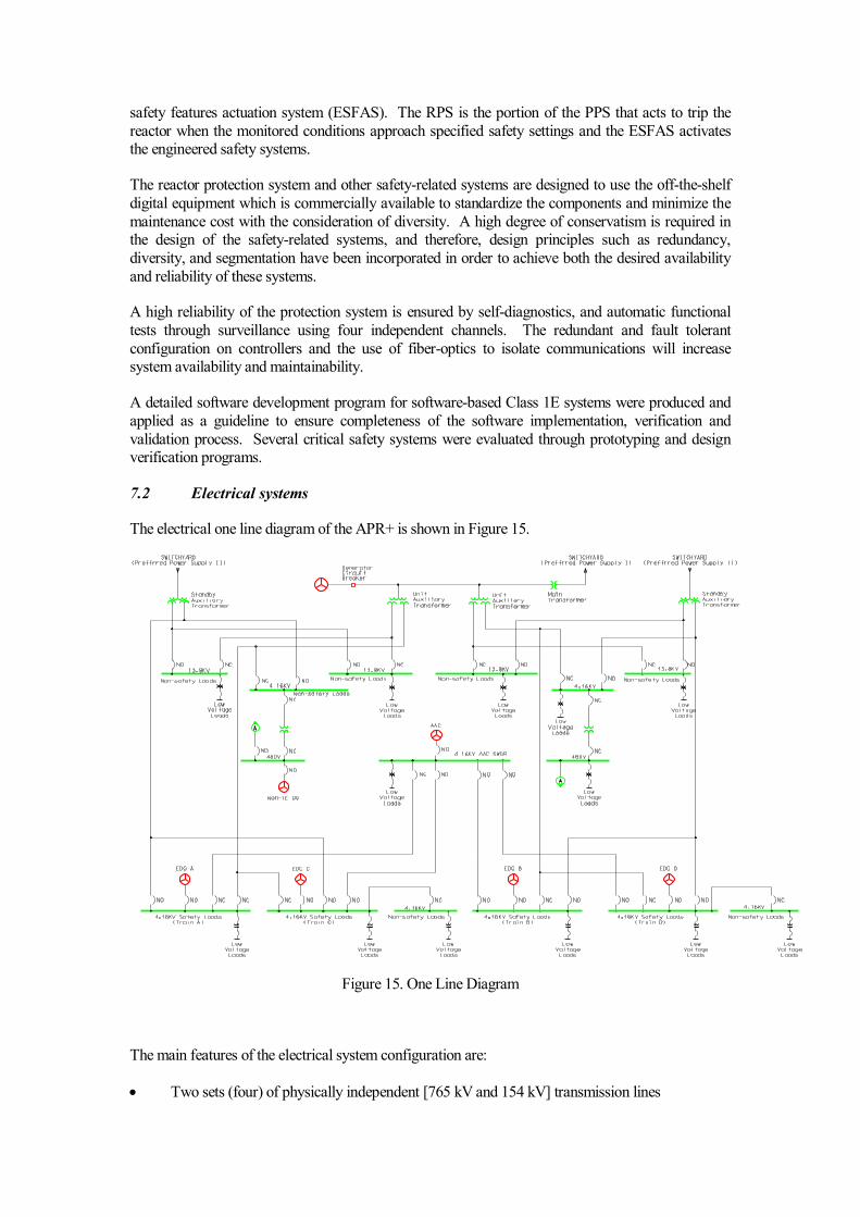
7.2 Electrical systems
The electrical one line diagram of the APR+ is shown in Figure 15.
Figure 15. One Line Diagram
The main features of the electrical system configuration are:
• Two sets (four) of physically independent [765 kV and 154 kV] transmission lines

• One main transformer consisting of three single-phase step-down transformers, and two three-
winding unit auxiliary transformers for power delivery and supply during normal operation
mode, and two three-winding stand-by transformers to supply power to the hot stand-by loads and the safe shutdown loads when the main transformer, isolated phase bus or unit auxiliary
transformers become unavailable
• Four Class 1E emergency diesel generators (DGs) to provide on-site stand-by power for the
Class 1E loads
• An alternate AC (AAC) source to provide power for equipment necessary to cope with station
blackout at least for 8 hours. For the diversity of emergency electrical power sources, the gas turbine type is selected for AAC
• Automatic transfer of power source from unit auxiliary transformers to standby auxiliary
transformers in the event of loss of power supply through the unit auxiliary transformers;
• Four independent Class 1E 125V DC systems
• Two non-class 1E 125V DC systems and one non-class 1E 250V DC system
• AC voltage levels of 13.8 kV and 4.16kV for medium, 480 V and 120V for low voltages.
7.2.1 Operational power supply systems
The main power system consists of the generator, generator circuit breaker, main transformer, unit
auxiliary transformer and stand-by transformer. The generator is connected to a gas-insulated 765 kV switchyard via the main transformer which is made of three single-phase transformer units.
Step-down unit auxiliary transformers are connected between the generator and main transformer,
and supply power to the unit equipment for plant startup, normal operation and shutdown. The
stand-by transformer is always energized and ready to ensure rapid power supply to the plant auxiliary equipment in the event of failure of the main and unit auxiliary transformers.
7.2.2 Safety-related systems
The electric power necessary for the safety-related systems is supplied through 4 alternative ways: firstly, the normal power source, i.e., the normal off-site power and the in-house generation through
the unit auxiliary transformer, secondly, the stand-by off-site power, i.e., the off-site power
connected through the stand-by transformer, thirdly, the on-site standby power supply, i.e., four emergency diesel generators, and finally, an alternative AC (AAC) diesel generator.
Among these power sources, the on-site standby power is the most crucial for safety. The
arrangement of the on-site electrical distribution system is based on the functional characteristics of
the equipment to ensure reliability and redundancy of power sources.
The on-site power supply is ensured by four independent Class 1E diesel generator sets. Each of
them is located in a separated building and is connected to one 4.16 kV safety bus. The AAC diesel
generator adds more redundancy to the electric power supply even though it is not a safety grade system. The non-class 1E AAC is provided to cope with Loss-of-Off-site-Power (LOOP) and
Station Blackout (SBO) situation which have a high potential for transients leading to severe
accidents. The AAC diesel generator is sized with sufficient capacity to accommodate the loads on one safety bus.
The 125 V DC systems consists of four independent, physically separated class 1E 125 V DC
subsystems (Train A, B, C, and D) corresponding to the four plant protection system trains. In
addition, two separated batteries as designated train C and D are provided to supply a required power to PAFS loads and RCGVS loads for 72 hours, respectively.

8. Spent Fuel and Waste management
The spent fuel from the reactor core is designed to be stored in the spent fuel pool located in the auxiliary building. The APR+ spent fuel pool has a capacity of storing the spent fuel
produced for 20 years, beyond which it is transferred to either off-site interim storage or
permanent disposal site. Radioactive waste management systems include those systems deal
with liquid, gaseous and solid wastes that may contain radioactive material. The liquid, gaseous and solid waste management systems are located in the compound building.
8.1 Liquid Waste Management System (LWMS)
The design objectives of the LWMS is to protect the plant personnel, the general public, and the
environment by providing a means to collect, segregate, store, process, sample, and monitor radioactive liquid waste. Liquid wastes are segregated according to waste types to minimize the
potential for mixing and contamination of non-radioactive flow streams. The processed liquid
radioactive waste is sampled prior to discharge from monitor tanks, and radiation monitors are
installed in the discharge line for a controlled monitored release.
The LWMS consists of collection tanks, process filter, reverse osmosis (R/O) packages, process
pumps, monitor tanks, and appropriate instrumentation and controls to permit remote operation
where necessary. Radioactive wastes are segregated by routing to an initial collection sump or tank. This allows more effective processing of each type of waste such that a derivative solid waste is
reduced. Several subsystems are available to process the different types of liquid waste.
The LWMS is divided into the following major subsystems:
• Floor Drain Subsystem
• Equipment Waste Subsystem
• Chemical Waste Subsystem
• Radioactive Laundry Subsystem (RLS)
8.2 Gaseous Waste Monitoring System (GWMS)
The GWMS is provided with radiation monitors that monitor the discharge from the charcoal delay beds upstream of the discharge to the Compound Building HVAC system. The GWMS consists of
two subsystems; the process gas subsystem and the process vent subsystem. The process vent
subsystem is designed as a part of building HVAC systems. The system is designed to collect, process, and monitor releases from all system input streams.
8.2.1 Process Gas Portion of GWMS
Process gases contain radioactive xenon and krypton fission which are fission products from fuel and
tramp uranium on fuel surfaces. The process gas portion of GWMS receives fission gases through
the gas surge header and uses charcoal delay beds to delay discharge and allow decay prior to
release. The primary input sources to the gas surge header are the chemical and volume control system (CVCS) gas stripper, volume control tank (VCT), reactor drain tank (RDT), and equipment
drain tank (EDT). The gases primarily consist of hydrogen and nitrogen with some trace quantities
of fission gases and oxygen. The removal of fission gases by the gas stripper maintains the fission gas concentration in the reactor coolant at a low level. This minimizes the escape of radioactive
gases during maintenance on the reactor coolant system and minimizes releases resulting from
leakage of reactor coolant.
8.2.2 Process Vent Portion of the GWMS

The process vent portion of the GWMS is designed to be connected to the low activity aerated gas
streams from the potentially contaminated HVAC vent headers in the Containment, Auxiliary Building, Turbine Building and Compound Building. The process vents, except from the condenser
vacuum system, are monitored, filtered, and released through the building HVAC systems. The
condenser vacuum system is monitored and then discharged without filtration.
8.3 Solid Waste Management System (SWMS)
The SWMS is designed to protect the plant personnel, the general public, and the environment by
providing a means to collect, segregate, store, process, sample, and monitor solid waste. The SWMS processes both wet solid active waste and dry active waste for on-site interim storage or shipment to
a licensed disposal site.
Primary functions of the SWMS are to process, package, and store spent resins, filters and concentrates from the LWMS, the chemical and volume control system (CVCS), the spent fuel pool
cooling and cleanup system (SFPCCS), and the steam generator blowdown system (SGBDS) in
accordance with regulatory guidelines.
The SWMS is subdivided into the following subsystems:
• Spent resin transfer and storage subsystem
• Filter handling subsystem
• Dry active waste sorting and segregation subsystem
• Drum drying subsystem
• Vitrification subsystem
9. Plant layout
9.1 Buildings and structures, including plot plan
The general arrangement of the APR+ was designed based on the twin-unit concept and slide-along arrangement with common facilities such as the compound building which includes radwaste
building and access control building. The general arrangement of the buildings is schematically
depicted in Figure 16. The auxiliary building which accommodates the safety systems and components surrounds the reactor containment building. The auxiliary and containment buildings
will be built on a common basemat. The common basemat will improve the resistance against
seismic events and reduce the number of walls between buildings so that rebar and formwork cost can be reduced.
The layout is highly influenced by safety considerations, in particular, by the physical separation
of equipment for the safety systems. Redundant 100% capacity safety systems are strictly separated
into four divisions. This divisional separation is provided for electrical, HVAC and mechanical safety systems. The four divisions of safety systems are consistent with an N+2 design concept. The
N+2 design concept is also applied to equipment arrangement in auxiliary building and emergency
diesel generator (EDG) building. Two independent EDG buildings are located on the symmetrically opposite sides of the auxiliary building, and each EDG building houses two EDG units in separate
rooms.

Figure 16. Plant General Arrangement
The building arrangement is also designed for the convenience of maintenance, considering accessi-
bility and replacement of equipment. The internal layout of the containment, in particular, is designed to allow the one-piece removal of the steam generator. With proper shielding and arrange-
ment of maintenance space, and careful routing of ventilation air flow, the occupational radiation
exposure is expected to be lower than 1 man-Sievert a year.
The design strength of the buildings in the safety category, which are the containment and the auxiliary buildings, is sufficient to withstand the effects of earthquakes up to the safe shutdown
earthquake (SSE) of 0.3 g. The containment and the auxiliary buildings are designed to withstand the
external hazards, such as an aircraft crash and missile impact, by fully hardened exterior wall design. EDG buildings are designed to perform their safety functions in the event of an aircraft crash by a
distance separation.
9.2 Reactor Building
The reactor building is the central building of the plant. Since the APR+ is a pressurized water
reactor, the reactor building essentially coincides with the containment building and, therefore, is
named as the reactor containment building. Figure 17 shows a cross-sectional view of the reactor containment building including a part of the auxiliary building with the arrangement of major
equipment.

Figure 17. Cross-sectional View of Reactor Containment Building
9.3 Containment
The reactor containment building is made of the post-tensioned cylindrical concrete wall with a steel liner, and reinforced concrete internal structures. The reactor containment building houses a reactor,
steam generators, pressurizer, reactor coolant loops, in-containment refueling water storage tank
(IRWST), and portions of the auxiliary systems. The reactor containment building is designed to
sustain all internal and external loading conditions which are reasonably expected to occur during the life of the plant.
The interior arrangement of the reactor containment building is designed to meet the requirements
for all anticipated conditions of operations and maintenance, including new and spent fuel handling. There are four main floor levels in the containment: the lowest floor level, called the ground floor,
the highest floor level, called operating floor, and the two mezzanine floors between ground and
operating floors. The two (2) mezzanine floors consist primarily of steel-supported gratings.
The equipment hatch is located at the operating floor level, and has an inside diameter of 8.2m (27 ft). This hatch size is selected to accommodate the one-piece replacement of a steam generator. A
polar bridge crane is supported from the containment wall. The bridge crane has the capability to
install and remove the steam generators. Personnel access from the auxiliary building to the containment is through two personnel airlocks, one located at the operating floor level and the other
at the ground floor elevation.
The containment is a post-tensioned concrete cylinder with an internal diameter of 46.6m (153 ft) and a hemispherical top dome. There is no structural connection between the free standing portion
of the containment and the adjacent structures other than penetrations and their supports. The lateral
loads due to seismic and other forces are transferred to the foundation concrete through the structural
concrete reinforcing connections.
9.4 Turbine building
The turbine building houses the turbine generator, the condenser systems, the preheater system, the
condensate and feedwater systems, and other systems associated with power generation. The turbine

building configuration is simplified for constructability, and the maintainability of the systems is
improved by centralizing the condensate polishing system, separating the switchgear building, and rearranging the equipment hatches. There are four main floor levels referred to as the basement,
ground level, operating level, and deaerator level.
The turbine building is classified as non-safety related. It has no major structural interface with other
buildings except for a seismic interface with the connecting auxiliary building. It is designed such that under SSE conditions, its failure will not cause the failure of safety related structures. The
turbine building is located such that the reactor containment building is at the high pressure turbine
side on the projection of the turbine shaft. This allows the optimization of the piping and cable routes to the nuclear island. This arrangement also minimizes the risk of damage to safety-related
equipment by missiles from the turbine or the generator, in the event of an accident. The vibration
problem which occurs during transient loading was minimized by moving the fresh water tank of the steam generator blowdown system to the auxiliary building.
In the APR+ plant, some of the items reflected in the general arrangement design are as follows:
• Relocation of the TBCCW heat exchanger into the turbine building ;
• Relocation of the secondary sample room & lab to the compound building;
• Simplification of contour of the turbine building super structure.
9.5 Other buildings
9.5.1 Auxiliary building arrangement
The auxiliary building completely surrounds the reactor containment building and is on the
common basemat which forms a monolithic structure with the reactor containment building. To
assure the safety and reliability, the auxiliary building is designed to enhance physical separation for the mitigation of internal flooding and fire propagation as shown in Figure 18.
According to the N+2 design concept, the divisional and quadrant separation concept is applied
to equipment arrangement of safety system located in the auxiliary building. A barrier, i.e., divisional and quadrant wall, is provided between divisions of safety system equipment. Mechanical
and electrical equipment of one division are completely separated from the other division by the
divisional and quadrant barrier. By applying this separation requirements, each train of the safety
systems is protected against propagation of internal hazards (e.g., fire, high energy line break, flooding) from one train to any other. The design basis of safety injection system, shutdown
cooling system, containment spray system, component cooling water system and essential chilled
water system is a four-train independent system.
The auxiliary building houses pumps and heat exchangers for the safety injection system and
shutdown cooling system. Also, the passive condensate cooling tanks, main control room and
fuel handling area are located in the auxiliary building. For the convenience of operation and
maintenance, there is a staging service area in the auxiliary building for installation work in front of the equipment hatch of the containment.
The reinforced exterior wall and roof protect the structures, systems and components in the auxiliary
building from the large commercial aircraft impact by preventing local perforation and scabbing failure.

CCWP (Component Cooling Water Pump), SC/CS Pump (Shutdown Cooling/Containment Spray Pump), SIP (Safety Injection Pump)
Figure 18. Quadrant Arrangement of Auxiliary Building
9.5.2 Compound building arrangement
The compound building houses system and components with the function of the radwaste
management and access control. The compound building consists of an access control facility, a radwaste management facility, a hot machine shop, vitrification facility, and sampling facilities &
lab. The compound building is designed to be shared between two units and is classified as non-
safety related. It has no major structural interface with other building. The access control is made at
the ground floor in the compound building.
The compound building is designed to be protected from natural phenomena such as flooding,
snowfall, earthquake, etc. and to accommodate loadings associated with environmental conditions to
the extent necessary to retain the spillage of potentially contaminated solids or liquids within the building.
9.5.3 Switchgear building
The switchgear building is located in the vicinity of the turbine building and all the electrical
switchgears are centralized in this area for the convenience of maintenance and efficiency of space
allocation.
9.5.4 Emergency diesel generator building
The two emergency diesel generator (EDG) buildings are located adjacent to the external walls of
the auxiliary building on opposite sides, providing physical separation for protection against external
hazards. Each EDG building houses two trains of diesel generator sets which are physically

separated by the interior dividing wall. One area of EDG building housing one diesel generator set
including related mechanical, electrical, I&C and HVAC equipment is protected against internal hazards caused by the other area of building..
The EDGs are arranged as separate entities with dedicated auxiliaries including air supply, exhausts,
and cooling systems, so that they are independent of each other in all respects.
10. Plant Performance
10.1 Operational performance
The APR+ design is optimized to achieve the high operational performance and to enhance the
convenience of maintenance by incorporating the following improvements. The lifetime design goal
of availability factor for the APR+ is above 92%.
10.1.1 Improvements for In-Service Inspection (ISI)
The reactor head is manufactured as one piece by integrating the flange and upper shell based on the
advanced forging capacity of manufacturer. In the conventional plant, the flange and upper shell are
fabricated separately and welded each other. This improvement reduces the girth seam, for which In-Service Inspection (ISI) have to be performed over the lifetime. Also, the work platforms are
installed to enhance the convenience of ISI for steam generators.
10.1.2 Enhanced refueling works
The fuel handling devices are improved to reduce the refueling time. In particular, a fuel transfer
tube, connecting the containment building and the fuel handling area in the auxiliary building, is
improved to be opened quickly by a remote control so that the radiation exposure is reduced. In addition, a temporary fuel storage rack can be installed inside of refueling pool to be used under an
abnormal condition during the refueling. The design of In-Core Instrument (ICI) cable tray is
improved to not install and disassemble for every refueling operation and the task related ICI cable is
simplified.
10.1.3 Design features for reducing unplanned trip
To reduce the unplanned reactor trip, the core thermal margin is designed to be increased above
10 % through lowering the core outlet temperate and increasing the RCS coolant flow. In addition, the pressurizer volume relative to power is enlarged to enhance a capability for coping with the
transients.
The turbine rotor is manufactured as one piece by forging to reduce the susceptibility of Stress
Corrosion Crack (SCC). The turbine control system of Mark VI is improved to enhance the reliability and maintainability by the redundant design of controllers and strengthening the diagnostic
functions and the visuals for operator. The vibration monitoring functions are improved by
strengthening the self-diagnostic functions of the detectors and multi-directional measurements. In addition, earthquake-proof structures are installed to prevent the turbine trip by high vibration.
The exciter is adopted as a static excitation type to reduce the mechanical wearing. The Auto-
Voltage Regulator (AVR) is placed in a dedicated room to minimize its malfunction by protecting it from heat and humidity. Also, the filtration abilities of the stator cooling water pipelines is
strengthened to not heat up by the reduced coolant flow.

The feedwater flow control system is designed to control the feedwater flow automatically over full
operation range and to operate three turbines driven main feedwater pumps during the normal power operation. When one main feedwater pump is tripped during the full power condition, other two
main feedwater pumps recover the total feedwater flow to the nominal value of full power condition.
This design reduces unnecessary power cutback and unplanned turbine trip.
10.2 Construction
Advanced construction technologies and design for constructability enhancement are
developed by the experience from the repeated APR1400 construction. Strategically,
modularization will be introduced to reduce the construction period for the APR+ plant.
The reactor containment building (RCB) and the auxiliary building will be built on a common
basemat. The layout of foundation is simplified so that it may have benefits to facilitate large reinforcing steel module and concrete works. The structural modules are implemented in the
internal structure and containment wall of the reactor building. The Steel-plate concrete (SC),
containment & dome liner plate, and IRWST stainless steel liner plate module will be
fabricated, lifted, and installed by a large capacity construction crane. New construction methods such as concrete placement technology for high lift, optimization of post tensioning
sequences are developed to enhance constructability. In the field of mechanical and electrical
work, RCL & RVI parallel construction, improve RCP internal and motor assembly method, MCR MMIS performance test, etc. are the main items of technical development in the APR+
plant.
An integrated composite module (ICM) based on the SC structures will be designed and
applied to the auxiliary and compound building, and will be fabricated, assembled, installed
after basemat concrete work to meet the construction schedule. If the ICMs are applied to the
building, the construction period will be dramatically reduced to 36 months from the first concrete to fuel load in the APR+ Nth plant. It is recommended that pre-fabrication portion in
the manufacturing shop as well as in the construction site shall be increased to improve
quality. In coincide with the supply contracts, ICM will be continuously and exclusively controlled to expedite both engineering, procurement through the data centric design system
in the A/E and fabrication, delivery of modules by fabricator or major constructor. KHNP also
considers the construction sequence and just-in-time delivery system. In the process of
fabrication, transportation, rigging and installation, connection methods module to module and deformation control techniques shall be improved in the next project. Bulk material
installation quantities such as large and small bore piping, cable tray and HVAC will be much
reduced through the ICM in auxiliary and compound building. Because these materials will be included in the ICM already, this will be helpful for reducing the construction schedule.
A construction technology of turbine building is also developed. Structural modules such as turbine roof truss preassembly, pedestal re-bar, etc. and mechanical module such as over head
crane assembly, condenser, and turbine hood assembly will be applied.
The APR+ Nth plant will be harmonically constructed within the desired schedule by applying a new process of optimum installation sequence and the state-of-the-art construction technologies.
10. 3 Construction schedule
The construction period of a nuclear power plant should be reduced in terms of economics. The
target of construction period for the APR+ N-th plant is 36 months from first concrete to fuel
loading. To meet the target construction period, several new engineering methods are adopted and

applied, such as a modularization, new construction method, construction process improvement
from reference plant, etc.
The modularization is widely known as a methodology to reduce the construction duration. It is one
of the most effective methods to enhance the economics of a nuclear power plant. The SC (Steel-
plate Concrete) module and integrated composite module will be mainly applied to the RCB, AB,
and CPB design. Also, the new construction method such as over the top method, RVI (Reactor Vessel Internal) module, RCL (Reactor Coolant Loop) & RVI parallel construction method are
adopted and applied to reduce the construction period.
Thus, the First-of-a-Kind plant of the APR+ will be constructed with the commercial operation target in 2022 and 2023 as Shin-Kori units 7&8. Also, KHNP expects that the N-th unit of the APR+
will be constructed within 36 months through experience, know-how for the APR+ 1st and 2
nd
construction projects.
11. Deployment status and planned schedule
According to the 5th basic electric power supply plan announced by the Ministry of Knowledge
Economy in October 2010, the Korean government established the construction plan of eleven nuclear power plants. Shin-Kori site is appointed for the place of the First-of-a-Kind plant of the
APR+ as the Shin-Kori nuclear units 7&8 (SKN 7&8), 1500MWe nuclear power plant. Currently,
Shin-Kori nuclear units 3&4 (SKN 3&4), the first APR1400 plants, are under construction at the Shin-Kori site located right next to the existing Kori nuclear power plant unit 1~4 under operation.
12. References
Standard Safety Analysis Report (SSAR) for the APR+ is the major reference and additional
information on the APR+ is available in KHNP websites.

Appendix: Summarized Technical Data for the APR+
General plant data
Reactor thermal output 4,290 MWth
Power plant output, gross 1,560 MWe
Power plant output, net 1,505 MWe
Power plant efficiency, net 35.1 %
Mode of operation Load Follow and
Baseload
Plant design life 60 Years
Plant availability target 92 %
Seismic design, SSE 0.3g
Primary Coolant material Light Water
Secondary Coolant material Light Water
Moderator material Light Water
Thermodynamic Cycle Rankine Cycle
Type of Cycle Indirect
Non-electric application N/A
Safety goals
Core damage frequency Less than 10-6
/RY
Large early release frequency Less than 10-7
/RY
Occupational radiation
exposure
1 Person-Sv/RY
Operator Action Time 0.5 Hours
Nuclear steam supply system
Steam flow rate at nominal
conditions
1,218.4 (per S/G) kg/s
Steam pressure/temperature 7.03 / 286 MPa(a)/℃
Feedwater flow rate at
nominal conditions
1,220.84 kg/s/SG
Feedwater temperature 232.2 ℃
Reactor coolant system
Primary coolant flow rate 21,658 kg/s
Reactor operating pressure 15.5 MPa(a)
Core coolant inlet temperature 291.7 ℃
Core coolant outlet
temperature
326.1 ℃
Mean temperature rise across
core
35.3 ℃
Reactor core
Active core height 3.81 m
Equivalent core diameter 3.77 m
Average linear heat rate 18.56 kW/m
Average fuel power density 38.93 kW/kgU
Average core power density 101.9 MW/m3
Fuel material UO2
Cladding tube material ZIRLO/HANA

Outer diameter of fuel rods 9.5 mm
Rod array of a fuel assembly Square lattice, 16x16
Number of fuel assemblies 257
Enrichment of reload fuel at
equilibrium core
4.47 (Batch Average) Wt%
Fuel cycle length 18 Months
Average discharge burnup of
fuel
45.8 MWd/kg
Burnable absorber
(strategy/material)
Gd2O3-UO2
Control rod absorber material B4C or Inconel Slug
Soluble neutron absorber H3BO3
Reactor pressure vessel
Inner diameter of cylindrical
shell
4,934.5 (Upper Shell)
4,963.9 (Lower Shell)
mm
Wall thickness of cylindrical
shell
313.5 (Upper Shell)
259.6 (Lower Shell)
mm
Total height, inside 14,297.2 mm
Base material SA508, Grade 3,
Class 1
Design pressure/temperature 17.2 / 343.3 MPa(a)/℃
Transport weight 633 T
Steam generator
Type Vertical U-tube with
integral economizer
Number 2
Total tube outside surface
area
15,683 (per S/G) m2/SG
Number of heat exchanger
tubes
13,102
Tube outside diameter 19.05 mm
Tube material SB-163 Alloy 690
Transport weight 846.7 T
Reactor coolant pump
Type Vertical, Single Stage
centrifugal with
bottom suction and
horizontal discharge
Number 4
Head at rated conditions 119 m
Flow at rated conditions 7.94 m3/s
Pump speed 1,190 rpm
Pressurizer
Total volume 80.7 m3
Steam volume: full
power/zero power
41.36/57.46 m3
Heating power of heater rods 3,000 kW

Primary containment
Type Prestressed Concrete
Structure
Overall form
(spherical/cylindrical)
Cylindrical
Dimensions (diameter/height) 46.63/77.19 m
Design pressure/temperature 0.515/143.33 MPa(a)/℃
Design leakage rate 0.15 Vol%/day
Is secondary containment
provided?
No
Residual heat removal systems
Active/passive systems Active & Passive
Safety injection systems
Active/passive systems Active & Passive
Turbine
Type of turbines TC-6F
Number of turbine sections
per unit (e.g. HP/MP/LP)
1/0/3
Turbine speed 1,800 rpm
HP turbine inlet
pressure/temperature
6.77/283.6 MPa(a)/℃
Generator
Type Direct Driven
(Water-Cooled)
Rated power 1,810 MVA
Active power 1,560 MW
Voltage 27 (3 phase) kV
Frequency 60 Hz
Total generator mass 713 T
Condenser
Type Steam Surface
Condenser pressure 5.08 kPa(a)
Feedwater pumps
Type TBN Driven
Number 3 (each 33.3 %)
Head at rated conditions 579 m
Flow at rated conditions 0.883 m3/s
Pump speed 4,570 rpm