Appypollo Recovery Operations - NASA · Lajes Field Ramstein RCC Ascension Island Sub RCC Asmara...
38
Apollo Recovery Operations Apollo Recovery Operations https://ntrs.nasa.gov/search.jsp?R=20090016307 2019-02-02T02:43:17+00:00Z
Transcript of Appypollo Recovery Operations - NASA · Lajes Field Ramstein RCC Ascension Island Sub RCC Asmara...

Apollo Recovery OperationsApollo Recovery Operationsp y pp y p
https://ntrs.nasa.gov/search.jsp?R=20090016307 2019-02-02T02:43:17+00:00Z

Objectives
Describe the organization of recovery force command and control and landing areas.and landing areas.
Describe the function and timeline use of the Earth Landing System (ELS).
Describe Stable 1 vs Stable 2 landing configurations and the function of the Command Module Uprighting System.
Explain the activities of the helicopter and swimmer teams in egressExplain the activities of the helicopter and swimmer teams in egress and recovery of the crew.
Explain the activities of the swimmer teams and primary recovery ship in recovery of the Command Moduleship in recovery of the Command Module.
Describe several landing incidents that occurred during Apollo.

Recovery Operations Overview
Recovery Force OrganizationLocation of Operations/Landing Areas
W lkth h f R A ti itiWalkthrough of Recovery ActivitiesELS/Parachute TimelineStable 1 or 2 Attitude
Recovery into Stable 1 AttitudeRecovery into Stable 1 AttitudeFinding the Command ModuleHelicopter OperationsSwimmer OperationsSwimmer Operations
Flotation CollarRecovery RaftCrew Egress and Air LiftgCM Recovery Operations
Apollo 16 Recovery TimelineApollo Landing Incidents
Apollo 15 ELS Incident
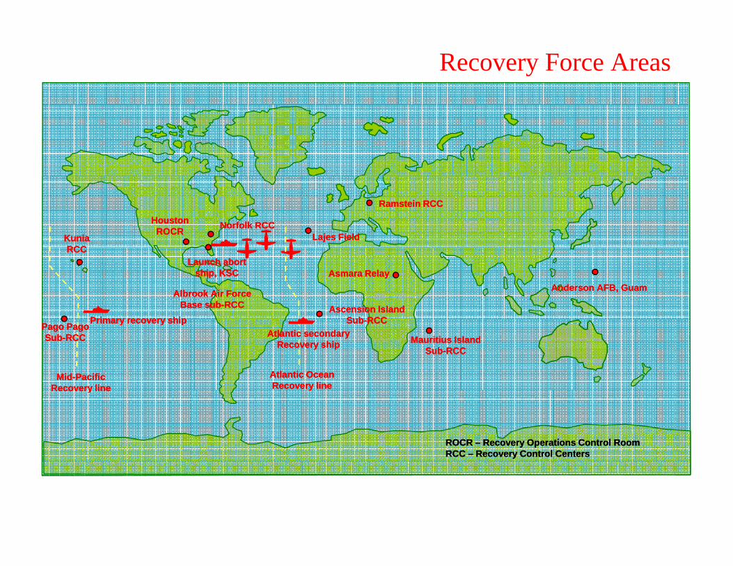
Recovery Force Areas
HoustonROCR
HoustonROCR Norfolk RCCNorfolk RCC
KuniaRCC
KuniaRCC
Lajes FieldLajes Field
Ramstein RCCRamstein RCC
RCCRCC
Ascension IslandSub RCC
Ascension IslandSub RCC
Asmara RelayAsmara RelayLaunch abort
ship, KSCLaunch abort
ship, KSC
Primary recovery shipPrimary recovery ship
Albrook Air ForceBase sub-RCC
Albrook Air ForceBase sub-RCC
Anderson AFB, GuamAnderson AFB, Guam
Sub-RCCSub-RCC
Mauritius IslandSub-RCC
Mauritius IslandSub-RCC
Primary recovery shipPrimary recovery ship
Atlantic OceanRecovery lineAtlantic OceanRecovery line
Mid-PacificRecovery line
Mid-PacificRecovery line
Atlantic secondaryRecovery ship
Atlantic secondaryRecovery ship
Pago PagoSub-RCC
Pago PagoSub-RCC
yyRecovery lineRecovery line
ROCR – Recovery Operations Control RoomRCC – Recovery Control CentersROCR – Recovery Operations Control RoomRCC – Recovery Control Centers

Earth Landing System (ELS)
Consisted of various parachutes and deployment mechanisms to decelerate the Command Module for a safe landingdecelerate the Command Module for a safe landing.
Forward Heat Shield Separation Parachute (Apex Cover)
2 Drogue Parachutes
3 Pilot Parachutes
3 Main Parachutes
A ti ti f t th h b t i it h d ti d l llActivation of system through barometric switches and time delays, as well as backup crew switches.
System was designed to safely operate with only two main chutes.

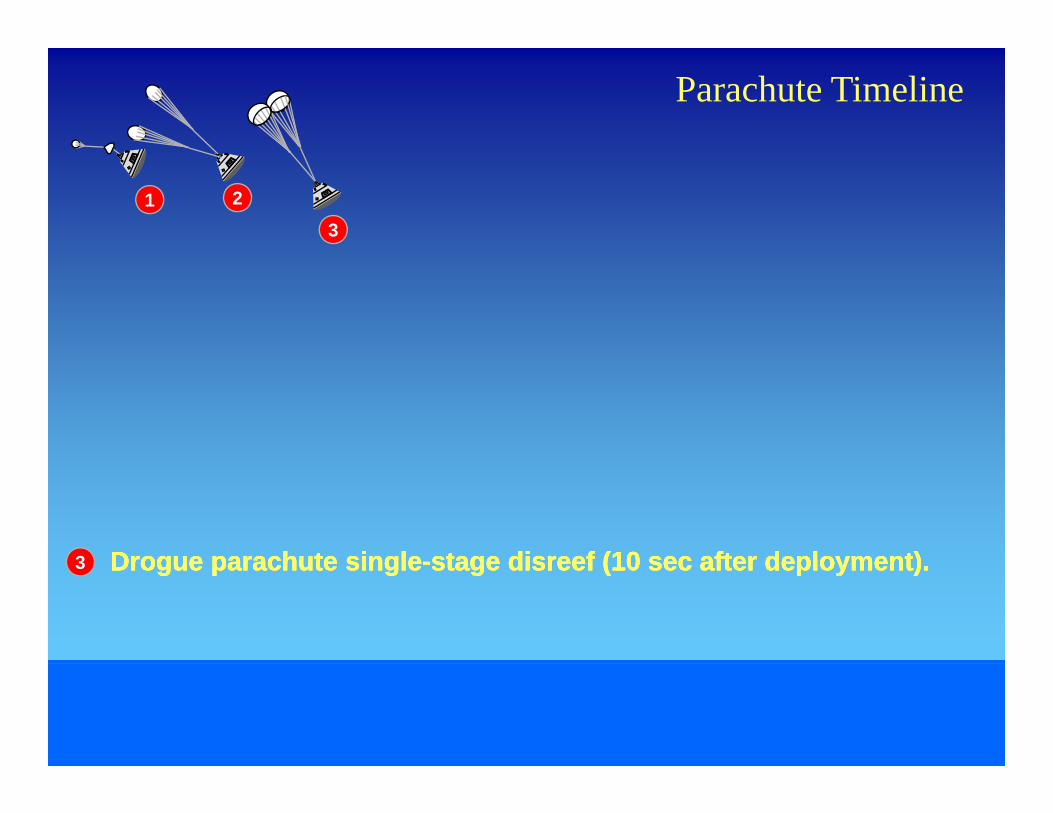
Parachute Timeline
1
1 Apex cover jettisoned at 24 000 ftApex cover jettisoned at 24 000 ft1 Apex cover jettisoned at 24,000 ft.Apex cover jettisoned at 24,000 ft.

Parachute Timeline
1 2
2 Drogue parachutes deployed reefed at 24 000 ft +2 secDrogue parachutes deployed reefed at 24 000 ft +2 secDrogue parachutes deployed reefed at 24 000 ft +2 secDrogue parachutes deployed reefed at 24 000 ft +2 sec2 Drogue parachutes deployed reefed at 24,000 ft +2 sec.Drogue parachutes deployed reefed at 24,000 ft +2 sec.Drogue parachutes deployed reefed at 24,000 ft +2 sec.Drogue parachutes deployed reefed at 24,000 ft +2 sec.
Parachute Timeline
1 23
3 Drogue parachute singleDrogue parachute single stage disreef (10 sec after deployment)stage disreef (10 sec after deployment)Drogue parachute singleDrogue parachute single stage disreef (10 sec after deployment)stage disreef (10 sec after deployment)3 Drogue parachute singleDrogue parachute single--stage disreef (10 sec after deployment).stage disreef (10 sec after deployment).Drogue parachute singleDrogue parachute single--stage disreef (10 sec after deployment).stage disreef (10 sec after deployment).
Parachute Timeline
1 23
4
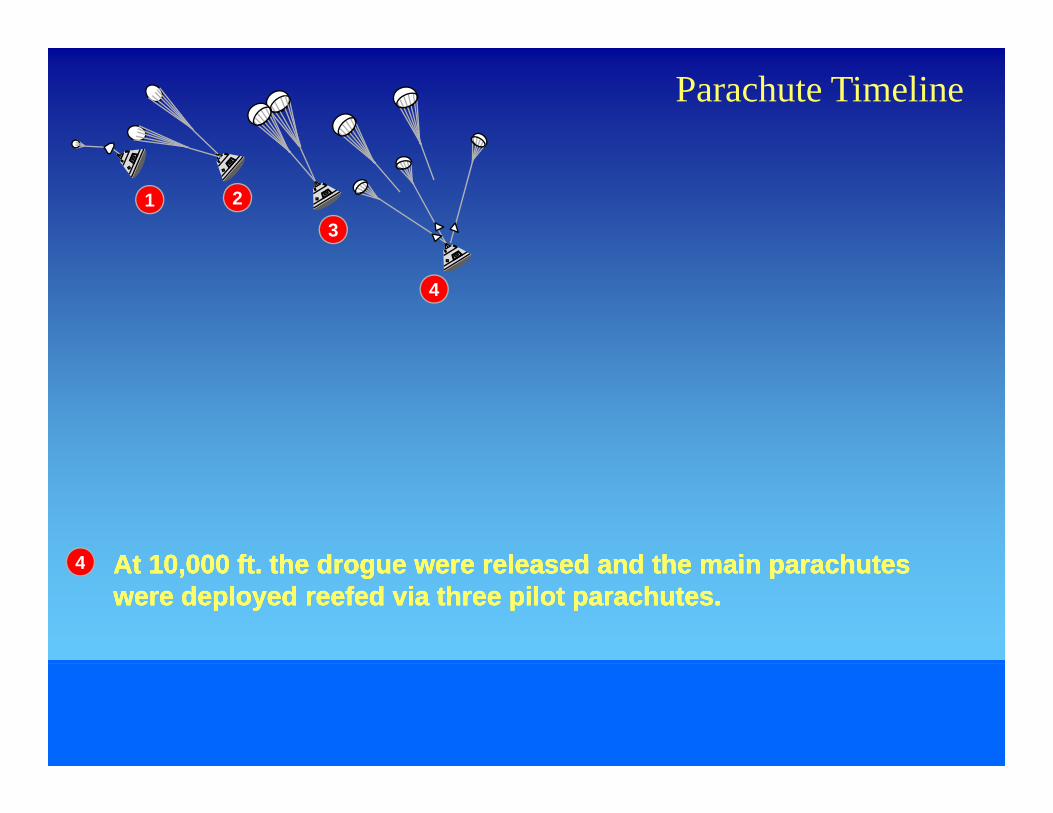
4 At 10 000 ft the drogue were released and the main parachutesAt 10 000 ft the drogue were released and the main parachutesAt 10 000 ft the drogue were released and the main parachutesAt 10 000 ft the drogue were released and the main parachutes4 At 10,000 ft. the drogue were released and the main parachutes At 10,000 ft. the drogue were released and the main parachutes were deployed reefed via three pilot parachutes.were deployed reefed via three pilot parachutes.At 10,000 ft. the drogue were released and the main parachutes At 10,000 ft. the drogue were released and the main parachutes were deployed reefed via three pilot parachutes.were deployed reefed via three pilot parachutes.

Parachute Timeline
1 23
4
5
5 Main parachute initial inflationMain parachute initial inflationMain parachute initial inflationMain parachute initial inflation5 Main parachute initial inflation.Main parachute initial inflation.Main parachute initial inflation.Main parachute initial inflation.

Parachute Timeline
1 23
4
5
66
6 Main parachute firstMain parachute first stage disreef (6 sec after deployment)stage disreef (6 sec after deployment)Main parachute firstMain parachute first stage disreef (6 sec after deployment)stage disreef (6 sec after deployment)6 Main parachute firstMain parachute first--stage disreef (6 sec after deployment).stage disreef (6 sec after deployment).Main parachute firstMain parachute first--stage disreef (6 sec after deployment).stage disreef (6 sec after deployment).

Parachute Timeline
1 23
4
5
66
77 VHF recovery antennas and flashing light deployedVHF recovery antennas and flashing light deployedVHF recovery antennas and flashing light deployedVHF recovery antennas and flashing light deployed7 VHF recovery antennas and flashing light deployed VHF recovery antennas and flashing light deployed
(8 sec after main parachute deployment).(8 sec after main parachute deployment).VHF recovery antennas and flashing light deployed VHF recovery antennas and flashing light deployed (8 sec after main parachute deployment).(8 sec after main parachute deployment).

Parachute Timeline
1 23
4
5
66
7 88 Main parachute secondMain parachute second stage disreef (10 sec afterstage disreef (10 sec afterMain parachute secondMain parachute second stage disreef (10 sec afterstage disreef (10 sec after8 Main parachute secondMain parachute second--stage disreef (10 sec after stage disreef (10 sec after
main parachute deployment). main parachute deployment). Main parachute secondMain parachute second--stage disreef (10 sec after stage disreef (10 sec after main parachute deployment). main parachute deployment).

Parachute Timeline
1 23
4
5
66
7 89 Main parachutes releasedMain parachutes releasedMain parachutes releasedMain parachutes released9 Main parachutes released.Main parachutes released.Main parachutes released.Main parachutes released.
9
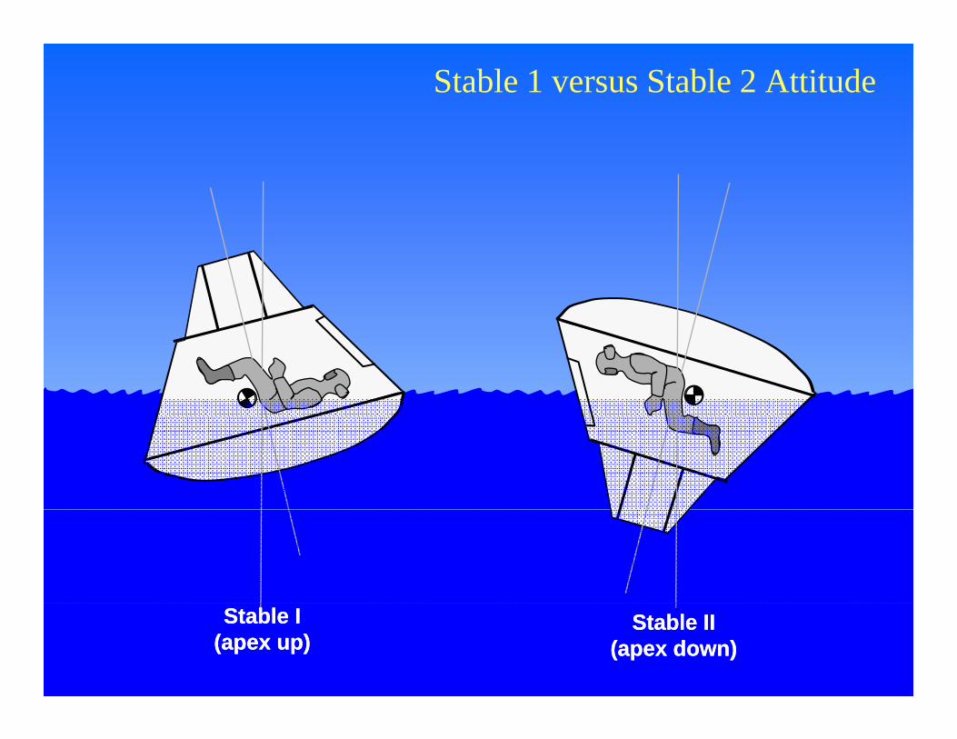
Stable 1 versus Stable 2 Attitude
Stable II(apex down)
Stable II(apex down)
Stable I(apex up)Stable I
(apex up)


3rd balloon hidden Recovery Hook
Command Module Uprighting SystemRecovery Hook
Uprighting balloon
U i hti b llUprighting balloon
If the system failed to upright the CM, a helicopter could be used to pull the CM upright using a line and the recovery hook which swimmers would attach.

Finding the Command Module
Airborne and Ship RADAR CM Flashing LightRADAR CM Flashing Light
?CM VHF Beacons CM Sea Dye Marker
?
Crew VHF Radio Communications

Finding the Command Module
Airborne and Ship RADAR
CM Flashing Light
Apollo 10 = 5.4 km (3.3mi)Apollo 11 = 24 km (14.9mi)Apollo 12 = 7.2 km (4.5mi)
CM VHF Beacons CM Sea DyeMarker
p ( )Apollo 13 = 6.4 km (4mi)Apollo 14 = 7 km (4.4mi)Apollo 15 = 10 km (6.2mi) Markerpo o 5 0 (6 )Apollo 16 = 5 km (3.1mi)Apollo 17 = 6.4 km (4mi)
Crew VHF Radio Communications

Helicopter Support
“Photo”“Recovery” “Swim” “ELS” “Apex” PhotoRecovery Swim ELS Apex
Primary helicopter for
Backup to the prime
Recover the Main Chutes
Recover drogue
Provide photographic
crew retrieval recovery helicopter
chutes and apex cover
support
Swimmer Operations
Sea Anchor attachment
Flotation Collar attachment
Recovery Raft attachmentRecovery Raft attachment
Assist with Astronaut Egress from CM
Assist with Astronaut Retrieval by Helicopter
Assist with CM Ship RecoveryAssist with CM Ship Recovery

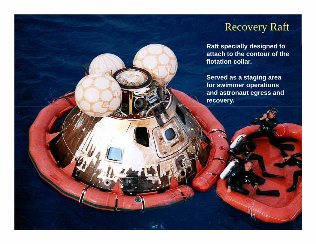
Raft specially designed to
Recovery RaftRaft specially designed to attach to the contour of the flotation collar.
S d t iServed as a staging area for swimmer operations and astronaut egress and recovery.

After recovery raft was attached to the flotation collar the crew
Crew Egress & Helicopter PickupAfter recovery raft was attached to the flotation collar, the crew opened the hatch and received life vests from the swimmer.
Swimmer assisted astronauts into the recovery raft.
Swimmer signaled recovery helicopter to move in and recover the crew.

Crew Egress & Helicopter Pickup
Helicopter hoist operator lowered recovery net to the raftHelicopter hoist operator lowered recovery net to the raft.
Crew were extracted one at a time to the helicopter.

Crew Egress & Helicopter Pickup
When all were onboard, the helicopter would take them to the primary recovery ship.
Swimmers would then prepare forSwimmers would then prepare for Command Module recovery operations.
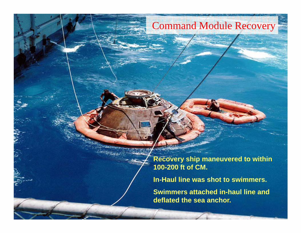
Command Module Recovery
Recovery ship maneuvered to withinRecovery ship maneuvered to within 100-200 ft of CM.
In-Haul line was shot to swimmers.
S i tt h d i h l li dSwimmers attached in-haul line and deflated the sea anchor.

Command Module Recovery
Recovery ship crane pulled CM alongside.
Recovery hook line and steady lines l d t ilowered to swimmers.
Swimmers connected lines to CM.

Command Module Recovery
CM lifted onto recovery ship.
In-haul LineIn-haul Line
Recovery Hook LineRecovery Hook Line
In-haul LineIn-haul Line
The CM was then placed on the Apollo CM Transport Dolly.
Flotation collar removed.
Steady LinesSteady Lines

Apollo 16 Recovery Timeline
EVENT LandingTime
hh/mmhh/mm
RADAR contact by Ticonderoga -00:11
Visual Contact -00:06
VHF recovery beacon contact by Ticonderoga -00:05VHF recovery beacon contact by Ticonderoga 00:05
Voice contact with Apollo 16 crew via VHF -00:04
Command module landing 00:00
Swimmers deployed to command module 00:05
Flotation collar installed and inflated 00:15
Hatch opened for crew egress 00:19
Flight crew aboard helicopter 00:31
Flight crew aboard Ticonderoga 00:37
Command module aboard Ticonderoga 01:39
Average recovery time was a little over two hours

Apollo Landing Incidents
Apollo 7, 8 and 11. Went to Stable 2Apollo 7, 8 and 11. Went to Stable 2 configuration after landing due to wind filling the main parachutes and pulling the CM over.

Apollo Landing Incidents
Apollo 12. Harder then normal landingApollo 12. Harder then normal landing due to the angle at which the CM entered the water. High winds and rough seas contributed to this
bl Th CM th t t St blproblem. The CM then went to a Stable 2 configuration.

Apollo Landing Incidents
Apollo 15 Loss of a main parachuteApollo 15. Loss of a main parachute. (More on this incident in a moment.)

Apollo Landing Incidents
Apollo 16. Went to a stable 2 configuration. Uprighting was initiated, g p g g ,but the crew reported that it seemed to delay in a partially uprighted position for longer then expected.
This was caused by the center uprighting bag only being partially inflated.

Apollo 15 Main Chute Failure
All three main parachutes deployed normally.
Aft R ti C t l S t d l tiAfter Reaction Control System depletion firing one of the chutes was noticed to be streaming at 6000 ft.
CM landed with only two main The good news was that the CM landed with only two main parachutes.
This resulted in a harder then normal landing and about 32 seconds sooner th t d
ELS had been designed to work safely with only two main parachutes operational.
then expected.

Apollo 15 Main Chute Failure
The prime suspect was the propellant damage from the RCS depletion firing.
A couple of other possibilities were looked at, tested, and discarded as cause.
RCS testing had shown that cold/raw fuel (monomethyl hydrazine) expulsion through a hot engine would burn.
The failed parachute was positioned above one of the roll engines during the fuel expulsion.
Based on RCS testing they determined that propellant damage from the RCS depletion firing probably caused the failure.
To mitigate this issue:
Landings could now occur with propellants onboard.
Biasing the propellant load to provide a slight excess of oxidizer.

Objectives
Describe the organization of recovery force command and control and landing areas.and landing areas.
Describe the function and timeline use of the Earth Landing System (ELS).
Describe Stable 1 vs Stable 2 landing configurations and the function of the Command Module Uprighting System.
Explain the activities of the helicopter and swimmer teams in egressExplain the activities of the helicopter and swimmer teams in egress and recovery of the crew.
Explain the activities of the swimmer teams and primary recovery ship in recovery of the Command Moduleship in recovery of the Command Module.
Describe several landing incidents that occurred during Apollo.

A ll WikiApollo Wiki
Apollo Recovery OperationsApollo Recovery Operationsp y pp y p