Approved Training Manual’s Lesson Plans And Courseware STAR MARIANAS AIR, INC. Initial New Hire...
38
Approved Training Manual’s Lesson Plans And Courseware STAR MARIANAS AIR, INC. Initial New Hire – Flight Crew Part III – Aircraft Ground Training Section 2 – Aircraft Systems
-
Upload
deirdre-neal -
Category
Documents
-
view
218 -
download
1
Transcript of Approved Training Manual’s Lesson Plans And Courseware STAR MARIANAS AIR, INC. Initial New Hire...

Approved Training Manual’sLesson Plans
AndCourseware
STAR MARIANAS AIR, INC.
Initial New Hire – Flight CrewPart III – Aircraft Ground Training
Section 2 – Aircraft Systems

Complete Class Roster Cell Phones OFF 10 Minutes Break every hour 1.0 Hour Class
Before We Start
Aircraft Ground Training:
Section 2 - Aircraft Systems

Current copy of the General Operations Manual Aircraft flight Manual
Training Materials
Aircraft Ground Training:
Section 2 - Aircraft Systems
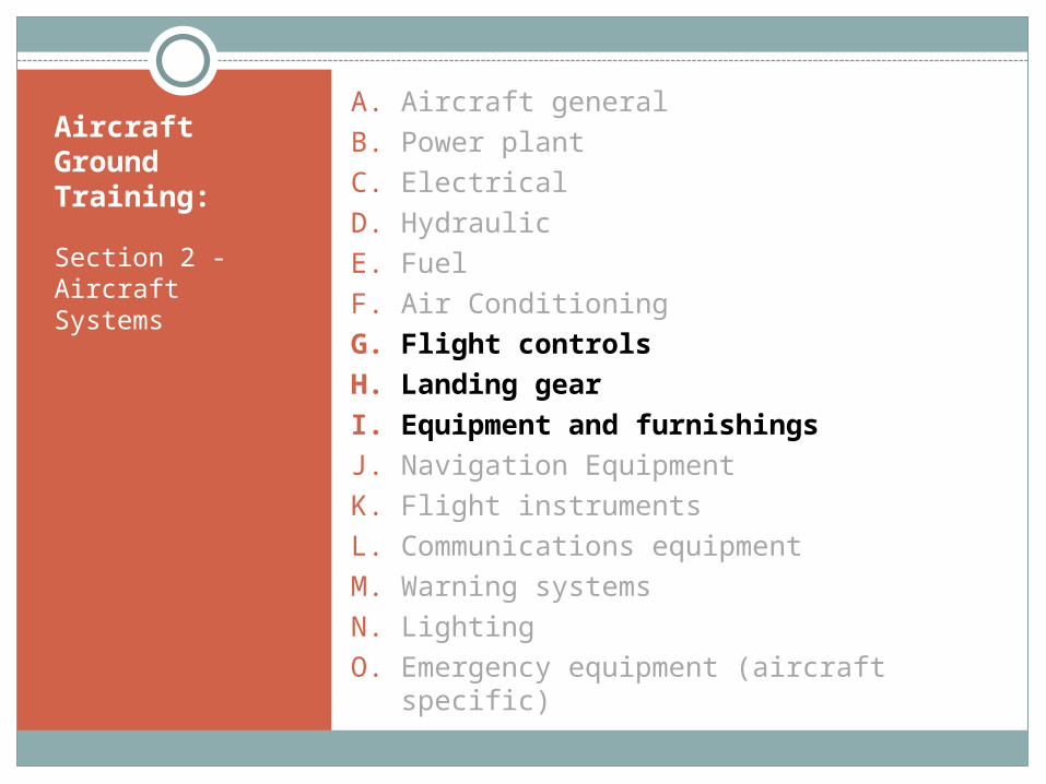
A. Aircraft general
B. Power plant
C. Electrical
D. Hydraulic
E. Fuel
F. Air Conditioning
G. Flight controls
H. Landing gear
I. Equipment and furnishings
J. Navigation Equipment
K. Flight instruments
L. Communications equipment
M. Warning systems
N. Lighting
O. Emergency equipment (aircraft specific)

Section 2 - Aircraft Systems
G. Flight controls
Aircraft Ground Training:

Aircraft Ground Training:
Section 2 - Aircraft Systems
G. Flight controls
1) Primary controls (yaw, pitch and roll devices)
2) Secondary controls (Leading/trailing edge devices, flaps, trim and dampening mechanisms)
3) Means of actuation (direct/indirect)

Aircraft Ground Training:
Section 2 - Aircraft Systems
Flight controls – Primary
The Cherokee Six is controlled in flight by the use of three standard primary control surfaces, consisting of:
• Ailerons,
• Stabilator and
• Rudder.
Operation of these controls is through the movement of the control column-tee bar assembly and rudder pedals.
On the forward end of each control column is a sprocket assembly. A chain is wrapped around the sprockets to connect the right and left controls and then back to idler sprockets on the column’s tee bar, which in turn connect to the aileron primary control cables.

Aircraft Ground Training:
Section 2 - Aircraft Systems
Flight controls – Primary
The cables operate the aileron bellcrank and push-pull rods.
The stabilator is controlled by a cable connected to the bottom of the tee bar assembly and at the balance arm of the stabilator.
Cables also connect the rudder pedals with the rudder horn.
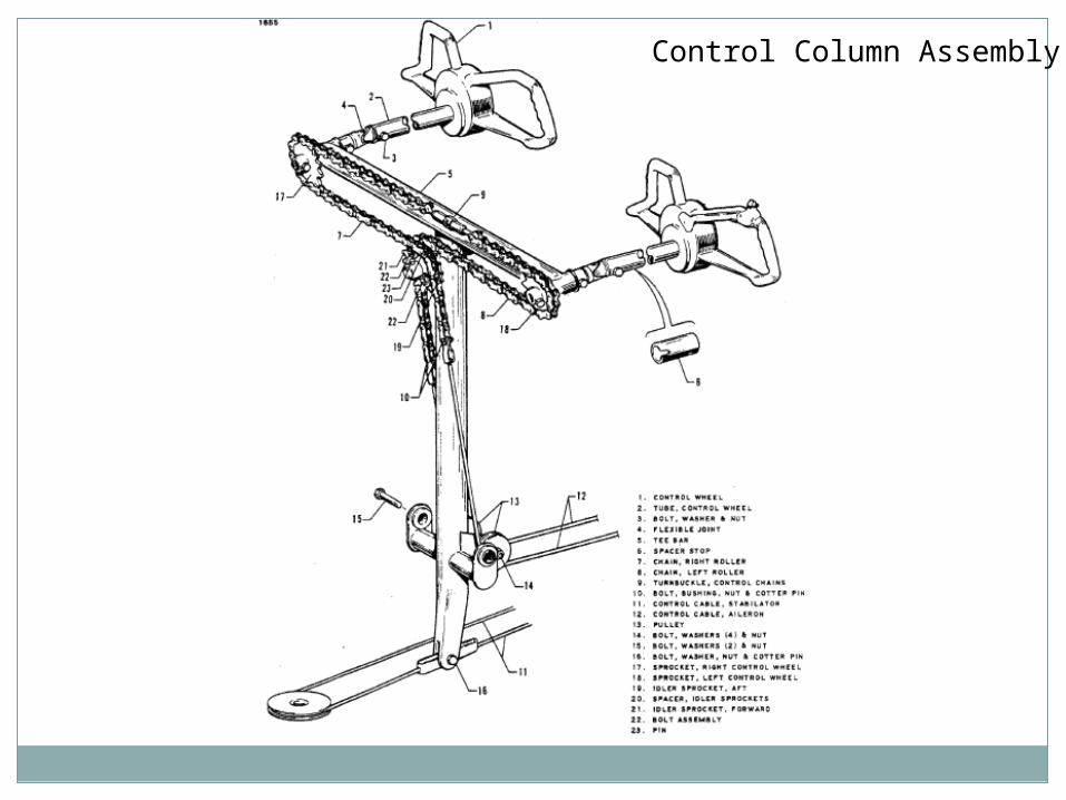
Control Column Assembly

Aileron Controls

Stabilator Controls

Rudder and Steering Pedal Assembly

Rudder Controls

Aircraft Ground Training:
Section 2 - Aircraft Systems
Flight controls – Trim
Provisions for directional and longitudinal trim control is provided by an adjustable trim mechanism for the stabilator and rudder.
The stabilator trim is controlled by a wheel and drum mounted on the floor tunnel between the front seats. Cables routed aft from the drum to the tail cone operate a screw assembly which in turn moves the stabilator trim tab.
The rudder trim is controlled by a knob and screw assembly attached to the rudder pedal assembly.

Stabilator Trim Control

Rudder Trim Controls
Aircraft Ground Training:
Section 2 - Aircraft Systems
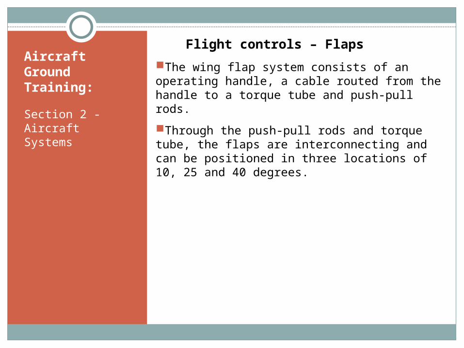
Flight controls – Flaps
The wing flap system consists of an operating handle, a cable routed from the handle to a torque tube and push-pull rods.
Through the push-pull rods and torque tube, the flaps are interconnecting and can be positioned in three locations of 10, 25 and 40 degrees.

Flap Controls

Section 2 - Aircraft Systems
H. Landing gear
Aircraft Ground Training:

Aircraft Ground Training:
Section 2 - Aircraft Systems
H. Landing gear
1) Brake system
2) Nose wheel steering
3) Landing gear system schematic
Aircraft Ground Training:
Section 2 - Aircraft Systems
Landing Gear - General
The landing gear incorporated on the PA-32 is a fixed, tricycle type, fitted with three 600 x 6 wheels.
The landing gear struts are of the air-oil type. Normal extension for nose gear = 3-1/4 inches. Normal extension for main gear = 4-1/2 inches.

Aircraft Ground Training:
Section 2 - Aircraft Systems
Landing Gear – Brake System
The two main wheels are equipped with a single disc hydraulic brake assembly which is actuated by a hand lever connected to a cylinder located below and behind the center of the instrument panel, or by individual cylinders attached to each rudder pedal.
The hand lever also doubles as a parking brake and may be operated by pulling back on the handle and pushing in on the button at the side of the handle.
To disengage the parking brake, pull back on the handle.
A brake fluid reservoir is installed on the left forward face of the engine firewall.

Brake System

Wheel Brake Assemblies

Toe Brake Installation Diagram

Aircraft Ground Training:
Section 2 - Aircraft Systems
Landing Gear – Nose Wheel Steering
The nose gear, steerable through a 60 degree arc, enables a 30 degree turn in each direction.
To aid in nose wheel and rudder centering and to provide rudder trim is a spring device attached to the rudder pedal torque tube assembly.
A shimmy dampener is also incorporated in the nose wheel steering mechanism.

Nose Gear Strut Assembly

Nose Wheel Steering Assembly

Section 2 - Aircraft Systems
I. Equipment and furnishings
Aircraft Ground Training:

Aircraft Ground Training:
Section 2 - Aircraft Systems
I. Equipment and furnishings
1) Exits, both normal and emergency
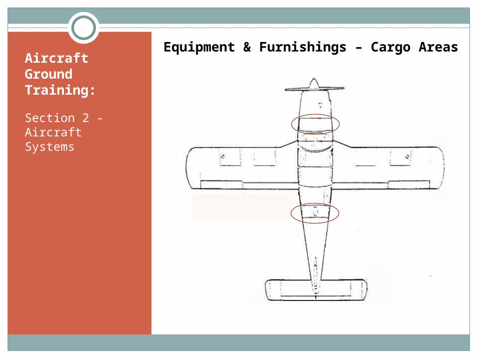
2) Cargo areas
3) Crewmember and passenger seats
4) Bulkheads
5) Seating and or cargo configurations
6) Non emergency equipment and furnishings

Aircraft Ground Training:
Section 2 - Aircraft Systems
Equipment & Furnishings - Exits
Aircraft Ground Training:
Section 2 - Aircraft Systems
Equipment & Furnishings – Cargo Areas

Aircraft Ground Training:
Section 2 - Aircraft Systems
Equipment & Furnishings – Crew and Passenger Seats
Front Seats Adjustable Forward and Aft
Center and Rear Seats Easily Removed for Additional Cargo Space

Aircraft Ground Training:
Section 2 - Aircraft Systems
Bulkheads
2 main bulkheads forward and aft.
Seating and or cargo configurations
N4599X does not have optional 7th seat installed
Rear and middle seats can be removed for larger cargo operations.
Non emergency equipment and furnishings
Class Discussion

Written examination required
Examination
Student Fill-out Student Feedback Form Sign Training Record (if applicable)
Instructor Sign Class Roster Fill-out Instructor Feedback Form Sign Training Record (if applicable)
Completion of Paperwork

E N D