Appraisal of underground energy storage potential in ... of underground... · Appraisal of...
171
Appraisal of underground energy storage potential in Northern Ireland Sustainable and Renewable Energy Programme Internal Report IR/06/095
Transcript of Appraisal of underground energy storage potential in ... of underground... · Appraisal of...

Appraisal of underground energy storage potential in Northern Ireland
Sustainable and Renewable Energy Programme
Internal Report IR/06/095

BRITISH GEOLOGICAL SURVEY
INTERNAL REPORT IR/06/095
Appraisal of underground energy storage potential in Northern Ireland
D.J. Evans, D.M. Reay, N.J. Riley, W.I. Mitchell and J. Busby
Contributors
G Earls and N.J. Riley
The National Grid and other Ordnance Survey data are used with the permission of the Controller of Her Majesty’s Stationery Office. Ordnance Survey licence number GD 272191/1999
Key words
Underground gas storage, oilfield, gasfield, energy, reservoir sandstone.
Front cover
Cover picture details, delete if no cover picture.
Bibliographical reference
D.J. EVANS, D.M. REAY, N.J. RILEY, W.I. MITCHELL AND J. BUSBY. 2006. Appraisal of underground energy storage potential in Northern Ireland. British Geological Survey Internal Report, IR/06/095. 17171pp.
© NERC 2006
Keyworth, Nottingham British Geological Survey 2006

The full range of Survey publications is available from the BGS Sales Desks at Nottingham and Edinburgh; see contact details below or shop online at www.thebgs.co.uk
The London Information Office maintains a reference collection of BGS publications including maps for consultation.
The Survey publishes an annual catalogue of its maps and other publications; this catalogue is available from any of the BGS Sales Desks.
The British Geological Survey carries out the geological survey of Great Britain and Northern Ireland (the latter as an agency service for the government of Northern Ireland), and of the surrounding continental shelf, as well as its basic research projects. It also undertakes programmes of British technical aid in geology in developing countries as arranged by the Department for International Development and other agencies.
The British Geological Survey is a component body of the Natural Environment Research Council.
Keyworth, Nottingham NG12 5GG 0115-936 3241 Fax 0115-936 3488
e-mail: [email protected] www.bgs.ac.uk Shop online at: www.thebgs.co.uk
Murchison House, West Mains Road, Edinburgh EH9 3LA 0131-667 1000 Fax 0131-668 2683
e-mail: [email protected]
London Information Office at the Natural History Museum (Earth Galleries), Exhibition Road, South Kensington, London SW7 2DE
020-7589 4090 Fax 020-7584 8270 020-7942 5344/45 email: [email protected]
Forde House, Park Five Business Centre, Harrier Way, Sowton, Exeter, Devon EX2 7HU
01392-445271 Fax 01392-445371
Geological Survey of Northern Ireland, Colby House, Stranmillis Court, Belfast BT9 5BF e-mail: [email protected] www.bgs.ac.uk/gsni
028-9038 8462 Fax 028-9038 8641
Maclean Building, Crowmarsh Gifford, Wallingford, Oxfordshire OX10 8BB
01491-838800 Fax 01491-692345
Parent Body
Natural Environment Research Council, Polaris House, North Star Avenue, Swindon, Wiltshire SN2 1EU
01793-411500 Fax 01793-411501 www.nerc.ac.uk
BRITISH GEOLOGICAL SURVEY

IR/06/095; Version 0.1 31st March 2006
i
Foreword Northern Ireland and the Republic of Ireland currently rely on imported natural gas to meet over 80% of the total energy demands of their economies. This gas comes into the island via undersea pipelines from Scotland, namely SNIP and the two Irish interconnectors (IC1 and IC2), respectively, which are served by a single pipeline route from Moffat in Scotland. There is an obvious vulnerability in a single supply route, potentially exposing Northern Ireland to shortages in the UK gas supply or failures on the pipeline network in the UK or elsewhere in Europe. Energy storage is, therefore, likely to become an increasingly important part of maintaining the reliability of energy supplies. Indeed, the published Northern Ireland energy strategy recognises the lack of storage for gas, on both an all-island context and in Northern Ireland itself, as an obstacle to maintaining reliable energy supplies.
Northern Ireland is unique to the island of Ireland in having relatively large aquifers and salt deposits onshore and close offshore. Such underground resources are routinely used in mainland Europe for the storage of natural gas and other products. Since the Second World War, these technologies have been deployed and developed around the world. This report seeks to evaluate the geological feasibility of deploying these storage technologies in the context of Northern Ireland energy and environmental goals, involving not just natural gas storage, but also the possibility of energy (including renewables) storage via compressed air, heat and hydrogen.
This scoping study is impartial and not linked to a particular industry, operator or technology. It also aims to raise awareness in government, industry and the public of how these natural resources might contribute to Northern Ireland’s future planning, energy security, efficiency and emissions reduction policy goals.
Disclaimer: this is an appraisal of the geological conditions and the technology of Underground Gas Storage (UGS) and energy storage (compressed air, ground source heat pump technology), NOT the control or prevention of pollution, safety of the surface or subsurface infrastructure. The assumption here being that the design, maintenance and operation of such facilities would be subject to the various HSE, waste and environmental regulations covered by such documents as the COSHH (2002), COMAH (1999) and appropriate British Standards. For specific elements of an underground gas storage facility, e.g. wells and surface installations, existing BS standards should be applied or referred to.
The British Geological Survey (BGS) has no responsibility for the persistence or accuracy of URLs for external or third-party internet websites referred to in this publication, and does not guarantee that any content on such websites is, or will remain, accurate or appropriate.
Acknowledgements BGS acknowledge the help and assistance offered by DETI during this project. Many colleagues are also thanked for their comments on various drafts of this report. Hugh Crilly (GSNI) prepared many of the diagrams of the geology of Northern Ireland.

IR/06/095; Version 0.1 31st March 2006
ii
Contents
Foreword .................................................................................................................................. i
Acknowledgements .......................................................................................................................... i
Contents ................................................................................................................................. ii
Executive Summary..................................................................................................................... viii
1 Introduction........................................................................................................... 1 1.1 Distributed Energy .................................................................................................. 3 1.2 Introduction to the British Geological Survey ........................................................ 3
2 The functions of energy storage........................................................................... 5 2.1 Moderating supply/demand gap .............................................................................. 5 2.2 Security of supply.................................................................................................... 5 2.3 Trading in the natural gas market............................................................................ 6
3 Energy storage in an all-island energy market .................................................. 7
4 The different types of underground (geological) energy/gas storage............. 12 4.1 Background ........................................................................................................... 12 4.2 Depleted oil and gas fields .................................................................................... 13 4.3 Aquifers................................................................................................................. 13 4.3.1 Reconditioned reservoirs, cushion and working gas............................................. 15
4.4 Salt cavity/solution mining.................................................................................... 15 4.4.1 Design concepts for gas storage caverns............................................................... 17
4.4.2 The stored products and pressure distribution in a salt cavern ............................. 17
4.5 Lined rock cavities ................................................................................................ 18 4.6 Abandoned/Reconditioned mines ......................................................................... 18
5 Forms of energy considered for underground storage.................................... 20 5.1 Underground Thermal Energy Storage ................................................................. 20 5.1.1 Sources of heat for storage .................................................................................... 21
5.1.2 High temperature underground thermal energy storage........................................ 21
5.2 Natural gas, LNG, CNG, LCNG and LPG............................................................ 22 5.2.1 The “Bishop Process”............................................................................................ 23
5.3 Compressed air (CAS) and compressed air energy storage (CAES) .................... 24 5.3.1 CAS ....................................................................................................................... 25
5.3.2 CAES..................................................................................................................... 25

IR/06/095; Version 0.1 31st March 2006
iii
5.3.3 Future technologies/developments........................................................................ 25
5.4 Hydrogen and renewable energy sources.............................................................. 26 5.4.1 Hydrogen production............................................................................................. 26
6 Description of energy storage facilities operational in the UK and around the world................................................................................................. 30
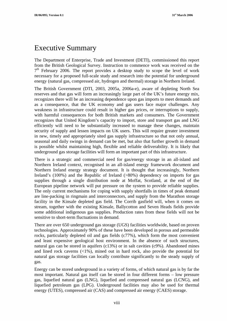
6.1 Underground thermal energy storage.................................................................... 30 6.1.1 Aquifer Thermal Energy Storage (ATES) ............................................................ 30
6.1.2 Borehole Thermal Energy Storage (BTES) .......................................................... 31
6.1.3 Cavern Thermal Energy Storage (CTES).............................................................. 31
6.1.4 Modelling and case histories ................................................................................. 31
6.2 UK examples of gas storage in depleting oil/gas fields ........................................ 32 6.2.1 Operational facilities in the UK ............................................................................ 32
6.2.2 Planned facilities in the UK .................................................................................. 35
6.3 Worldwide Examples of aquifer storage............................................................... 36 6.4 Examples of storage of different types of energy in salt caverns and other
geological environments ....................................................................................... 39 6.4.1 Hydrogen storage .................................................................................................. 39
6.4.2 Compressed air (CAS) and compressed air energy storage (CAES) .................... 40
6.4.3 Natural gas............................................................................................................. 44
6.4.4 Lined Rock Caverns .............................................................................................. 44
7 Outline of the geology of Northern Ireland ...................................................... 47 7.1 Onshore geology ................................................................................................... 47 7.1.1 Basement ............................................................................................................... 48
7.1.2 Late Palaeozoic to Palaeogene ‘cover’.................................................................. 51
7.2 Detailed Geology of the Permian and Triassic rocks of Northern Ireland............ 54 7.2.1 Permian.................................................................................................................. 55
7.2.2 Triassic .................................................................................................................. 67
7.2.3 Geological structure in the Larne area .................................................................. 72
7.2.4 Potential of salt beds in Larne Basin for energy storage in caverns ..................... 75
7.3 Suitability (onshore) of Northern Ireland rock units for underground energy storage ....................................................................................................... 77
7.3.1 Proterozoic (Dalradian Supergroup) ..................................................................... 77
7.3.2 Ordovician (Tyrone Igneous Complex) ................................................................ 79
7.3.3 Ordovician-Silurian (Leadhills Supergroup, Gala and Hawick groups) ............... 80
7.3.4 Devonian (Newry Igneous Complex) ................................................................... 81
7.3.5 Devonian sedimentary and volcanic rocks............................................................ 82
7.3.6 Carboniferous ........................................................................................................ 83

IR/06/095; Version 0.1 31st March 2006
iv
7.3.7 Permian.................................................................................................................. 84
7.3.8 Triassic .................................................................................................................. 86
7.3.9 Jurassic-Cretaceous ............................................................................................... 87
7.3.10 Palaeogene (Antrim Lava Group) ......................................................................... 89
7.3.11 Mourne Mountains and Slieve Gullion Igneous Complexes ................................ 91
7.3.12 Lough Neagh Group.............................................................................................. 92
7.3.13 Summary ............................................................................................................... 93
7.4 Offshore geology................................................................................................... 96 7.4.1 Sedimentary Basins ............................................................................................... 98
7.4.2 Potential for underground storage in sedimentary basins offshore Northern Ireland ................................................................................................................. 103
8 Incidents at underground gas storage facilities.............................................. 104 8.1 Introduction ......................................................................................................... 104 8.2 Comment on the UGS accidents relative to other areas of the oil/gas
supply industry.................................................................................................... 106 8.3 Summary ............................................................................................................. 108
9 Legislation, British and European Standards ................................................ 111 9.1 British/European Standards................................................................................. 112 9.2 Legislative framework and principal bodies involved in Northern Ireland
and Great Britain................................................................................................. 112 9.2.1 Exploration in Northern Ireland .......................................................................... 113
9.2.2 The Planning Service and Planning Legislation in Northern Ireland.................. 114
9.2.3 Health and Safety Legislation ............................................................................. 116
10 Conclusions........................................................................................................ 123
11 Recommendations ............................................................................................. 124
References ............................................................................................................................. 126
Appendix 1 Geological Survey of Northern Ireland field maps of the Larne area ......... 135
Appendix 2 Comparison of gamma ray and sonic logs for the Permian and Triassic Larne halites in the Larne No. 2 borehole........................................ 139
Appendix 3 Incidents at underground gas storage facilities.............................................. 140

IR/06/095; Version 0.1 31st March 2006
v
FIGURES
Figure 1 Map of the pipeline network in Northern Ireland (Source: Bord Gàis website) ............. 8
Figure 2 Detail of the onshore pipeline connections for SNIP, IC1 and IC2 (after CER 2005) ....................................................................................................................... 9
Figure 3 Northern Ireland Energy Infrastructure (Source: DETI Intranet-Energy Division) ...... 10
Figure 4 Sketch examples of the types of underground gas storage scenarios, with typical durations and range for deliverability. Figures in brackets represent the typical range in days for storage in that facility type (after Plaat, 2004)................................... 12
Figure 5 Three different types of underground thermal energy storage (after Sanner, 2003). ............................................................................................................................. 21
Figure 6. Schematic of liquefied and compressed natural gas facility (after Wegrzyn and Litzke, 1999). ................................................................................................................. 23
Figure 7 Diagrammatic representation of the “Bishop Process” (after Conversion Gas Imports L.P.). ................................................................................................................. 24
Figure 8 Processes of hydrogen production from natural gas and CO2 capture and underground storage (based upon and after IEA, 2006). ............................................... 27
Figure 9 Schematic of the BP Peterhead hydrogen production and use, CO2 storage and enhanced oil recovery project (courtesy of BP)............................................................. 28
Figure 10 Basic principles of aquifer thermal energy storage ..................................................... 30
Figure 11 Humbly Grove gas storage facility (after Star Energy). a) site clearance (Feb 2004) and b and c) completed facility (Feb 2005). ........................................................ 34
Figure 12 Map of the Kinsale area gasfields (after Marathon Oil).............................................. 34
Figure 13 Distribution of gas aquifer storage facilities in Northwest Europe (after Gasunie). ........................................................................................................................ 36
Figure 14 Sketch cross section illustrating the setting of the Lussagnet aquifer storage facility in SW France (after Gourlia, 2006). .................................................................. 37
Figure 15 Map and sketch showing the location and style of the Stenlille aquifer storage site in Denmark (after Laier and Øbro, 2004). .............................................................. 37
Figure 16 Sketch of the Stenlille aquifer storage site illustrating the depths and general structure of the aquifer and the underlying salt pillow responsible for the gentle anticline forming the ‘trap’ (after Laier and Øbro, 2004).............................................. 38
Figure 17 Tees Valley hydrogen infrastructure (after University of Salford). ............................ 40
Figure 18 Aerial view of the Huntorf CAES plant (photograph after Crotogino et al., 2001). ............................................................................................................................. 41
Figure 19 The McIntosh CAES plant, Alabama (photograph after Haug, 2005) ......................... 42
Figure 20 Diagramatic representation of the proposed Norton CAES plant at Norton, Ohio (after Sandia and CAES Development Company LLC). .................................... 43
Figure 21 Diagrammatic representation of the Iowa CAES scheme (after Holst, 2005). ........... 44

IR/06/095; Version 0.1 31st March 2006
vi
Figure 22 Sketch diagram of the Skallen LRC demonstration plant in Sweden (after Vasques and Tengborg, 2001) ..................................................................................... 46
Figure 23 Simplified geological map of Northern Ireland. (after Mitchell, 2004) ...................... 47
Figure 24 Configuration of basement terranes in Northern Ireland. (after Mitchell, 2004) ........ 49
Figure 25 Geological divisions of Northern Ireland (after Mitchell, 2004) ................................ 50
Figure 26 Location of Permo-Triassic basins in Northern Ireland (after Mitchell, 2004)........... 54
Figure 27 Distribution of Permian, Triassic and Jurassic rocks in Northern Ireland (after Mitchell, 2004) ............................................................................................................. 56
Figure 28 Correlation of Permian rocks from outcrops and boreholes in Northern Ireland (after Mitchell, 2004) ................................................................................................... 58
Figure 29 Detail of the geology in the Carrickfergus – Larne region. (GSNI, 1997).................. 59
Figure 30 Larne Basin: seismic section across Ballytober Horst showing possible Triassic salt beds west of the Ballytober Fault (after Mitchell, 2004) ...................................... 61
Figure 31 Bouguer gravity anomaly image with shaded relief, illumination from the NW........ 62
Figure 32 Bedrock geology of Larne area (GSNI, 1994), showing seismic lines and possible extensions of known major faults (dashed red lines). Area enclosed by yellow indicates where the interpreted Top Magnesian Limestone reflector is at a two way time (TWT) equal to, or greater than, that measured in Larne No. 2. ........ 63
Figure 33 Correlation of seismic section NI-81/B with synthetic seismogram from Larne No.2, showing reflector packages associated with Permian and Triassic salt intervals (sources: Department of Commerce, 1981and Penn, 1981). ........................ 64
Figure 34 Bouguer gravity anomaly map of the Rathlin Basin showing the main depocentres in blue (source: BGS) .............................................................................. 65
Figure 35 Summary successions and correlation of selected Triassic sequences in Northern Ireland. (after Mitchell, 2004) ...................................................................... 69
Figure 36 Comparison of the Triassic rocks in the Port More and Larne No. 2 boreholes ......... 74
Figure 37 Distribution of Dalradian rocks in Northern Ireland (after Mitchell, 2004) ................ 77
Figure 38 Tyrone Igneous Complex (after Mitchell, 2004)........................................................ 79
Figure 39 Lower Palaeozoic rocks of counties Down and Armagh (after Mitchell, 2004)......... 80
Figure 40 Newry Igneous Complex (after Mitchell, 2004) ......................................................... 81
Figure 41 Distribution of Devonian rocks in counties Antrim, Fermanagh and Tyrone (after Mitchell, 2004) ................................................................................................... 82
Figure 42 Distribution of Carboniferous rocks in Northern Ireland (after Mitchell, 2004) ........ 83
Figure 43 Reservoir quality: porosity-permeability crossplot for Sherwood Sandstone Group and Permian sandstones in Northern Ireland wells. (after Mitchell, 2004) ...... 85
Figure 44 Distribution of Cretaceous rocks in Northern Ireland (after Mitchell, 2004).............. 88
Figure 45 Distribution of Antrim Lava Group and Lough Neagh Clay Group rocks (after Mitchell, 2004) ...................................................................................................................... 90
Figure 46 Offshore basins to Northern Ireland (after Mitchell, 2004) ........................................ 96

IR/06/095; Version 0.1 31st March 2006
vii
Figure 47 Approximate depositional limits of individual halites within the Mercia Mudstone Group (based upon Jackson et al., 1995). ............................................................ 97
Figure 48 Location of seismic lines and deep boreholes in the Larne Basin, both on- and offshore (sources: www.ukdeal.co.uk for offshore data and GSNI data archives for onshore)................................................................................................................................. 99
Figure 49 Comparative lithostratigraphy of the Triassic rocks in the 111/15-1 well and the Larne No. 2 borehole (for location of boreholes see Fig. 48) ........................................ 101
TABLES
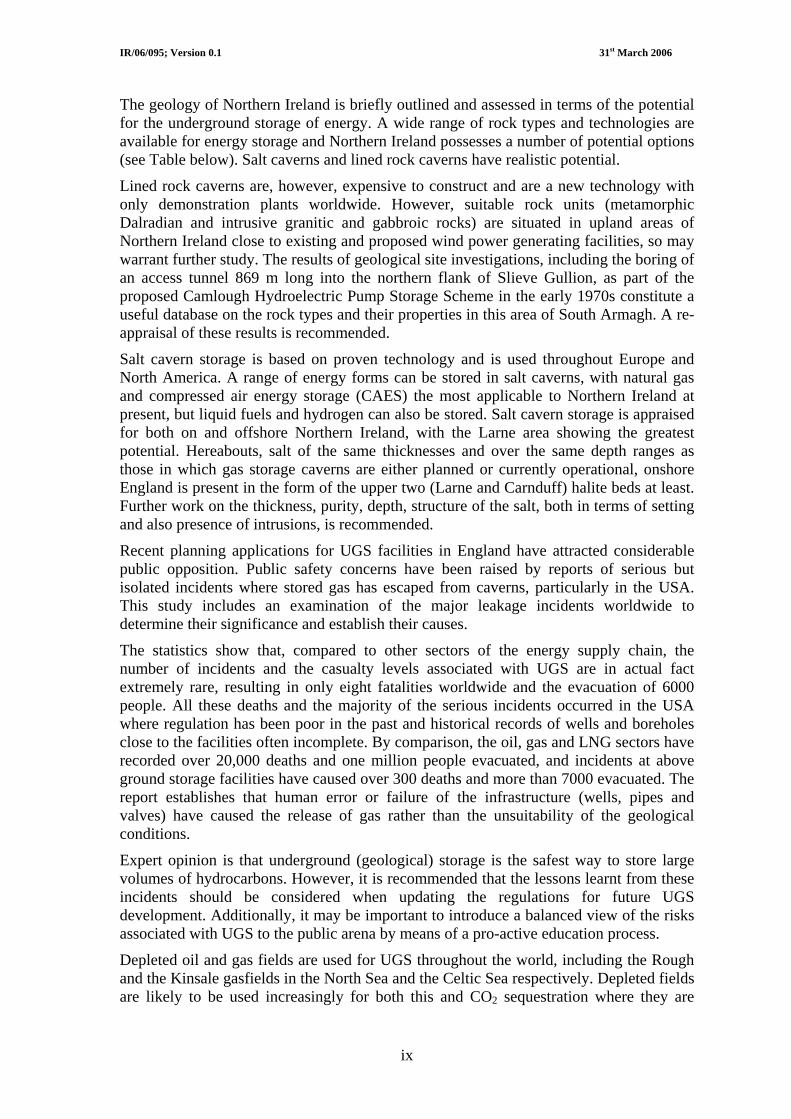
Table 1 Possible heat sources and users for underground thermal energy storage. ................... 22
Table 2. Proposed gas storage facilities in depleted/depleting oil and gas fields onshore England (based upon DTI, 2005 – Secretary of State’s First Report to Parliament on Security of Gas and Electricity Supply in Great Britain, July 2005; Energy Review - DTI, 2006). 35
Table 3. Existing and planned salt cavern storage as of March 2006. 45
Table 4 Geological succession of the rocks in Northern Ireland . 48
Table 5 Provings of Permian salt in boreholes of the Larne Basin 60
Table 6 Comparison of geophysical well log responses of pure NaCl, Larne and Permian halites. 60
Table 7 Triassic salt beds in Larne and Newmill boreholes 70
Table 8 Analyses of salt samples from Larne Halite Member in Larne No. 1 cores 71
Table 9 Analyses of salt samples from Duncrue mine 71
Table 10 Properties of Permian and Triassic salt beds in the Larne area 76
Table 11 Potential suitability of rocks in Northern Ireland for underground energy storage 95
Table 12 (following page). Summary of catastrophic events involving salt cavern storage in the USA since 1972. 104
Table 13 Summary of main casualty figures from various oil, gas and petrochemical incidents in the USA and rest of the world. Figures relating to OPS and HSE for domestic gas supplies partly duplicate those pipeline figures in the USA published by Hirschberg et al. (1998) and which were the major incidents covered in NTSB reports. 107
Table 14 Salt Cavity Storage and the Minerals Development Act (Northern Ireland) 1969 113
Table 15 List of Regional Planning Policies for Minerals 115
IR/06/095; Version 0.1 31st March 2006
viii
Executive Summary The Department of Enterprise, Trade and Investment (DETI), commissioned this report from the British Geological Survey. Instruction to commence work was received on the 7th February 2006. The report provides a desktop study to scope the level of work necessary for a proposed full-scale study and research into the potential for underground energy (natural gas, compressed air, hydrogen and thermal) storage in Northern Ireland.
The British Government (DTI, 2003, 2005a, 2006a-e), aware of depleting North Sea reserves and that gas will form an increasingly large part of the UK’s future energy mix, recognizes there will be an increasing dependence upon gas imports to meet demands and as a consequence, that the UK economy and gas users face major challenges. Any weakness in infrastructure could result in higher gas prices, or interruptions to supply, with harmful consequences for both British markets and consumers. The Government recognizes that United Kingdom’s capacity to import, store and transport gas and LNG efficiently will need to be substantially increased to manage these changes, maintain security of supply and lessen impacts on UK users. This will require greater investment in new, timely and appropriately sited gas supply infrastructure so that not only annual, seasonal and daily swings in demand can be met, but also that further growth in demand is possible whilst maintaining high, flexible and reliable deliverability. It is likely that underground gas storage facilities will form an important part of this infrastructure.
There is a strategic and commercial need for gas/energy storage in an all-island and Northern Ireland context, recognised in an all-island energy framework document and Northern Ireland energy strategy document. It is thought that increasingly, Northern Ireland’s (100%) and the Republic of Ireland (>80%) dependency on imports for gas supplies through a single distribution node at Moffat, Scotland, at the end of the European pipeline network will put pressure on the system to provide reliable supplies. The only current mechanisms for coping with supply shortfalls in times of peak demand are line-packing in ringmain and interconnectors, and supply from the Marathon storage facility in the Kinsale depleted gas field. The Corrib gasfield will, when it comes on stream, together with the existing Kinsale, Ballycotton and Seven Heads fields provide some additional indigenous gas supplies. Production rates from these fields will not be sensitive to short-term fluctuations in demand.
There are over 650 underground gas storage (UGS) facilities worldwide, based on proven technologies. Approximately 90% of these have been developed in porous and permeable rocks, particularly depleted oil and gas fields (c77%), which form the most convenient and least expensive geological host environment. In the absence of such structures, natural gas can be stored in aquifers (c13%) or in salt cavities (c9%). Abandoned mines and lined rock caverns (<1%), mined out in hard rock, also provide the potential for natural gas storage facilities can locally contribute significantly to the steady supply of gas.
Energy can be stored underground in a variety of forms, of which natural gas is by far the most important. Natural gas itself can be stored in four different forms – low pressure gas, liquefied natural gas (LNG), liquefied and compressed natural gas (LCNG), and liquefied petroleum gas (LPG). Underground facilities may also be used for thermal energy (UTES), compressed air (CAS) and compressed air energy (CAES) storage.
IR/06/095; Version 0.1 31st March 2006
ix
The geology of Northern Ireland is briefly outlined and assessed in terms of the potential for the underground storage of energy. A wide range of rock types and technologies are available for energy storage and Northern Ireland possesses a number of potential options (see Table below). Salt caverns and lined rock caverns have realistic potential.
Lined rock caverns are, however, expensive to construct and are a new technology with only demonstration plants worldwide. However, suitable rock units (metamorphic Dalradian and intrusive granitic and gabbroic rocks) are situated in upland areas of Northern Ireland close to existing and proposed wind power generating facilities, so may warrant further study. The results of geological site investigations, including the boring of an access tunnel 869 m long into the northern flank of Slieve Gullion, as part of the proposed Camlough Hydroelectric Pump Storage Scheme in the early 1970s constitute a useful database on the rock types and their properties in this area of South Armagh. A re-appraisal of these results is recommended.
Salt cavern storage is based on proven technology and is used throughout Europe and North America. A range of energy forms can be stored in salt caverns, with natural gas and compressed air energy storage (CAES) the most applicable to Northern Ireland at present, but liquid fuels and hydrogen can also be stored. Salt cavern storage is appraised for both on and offshore Northern Ireland, with the Larne area showing the greatest potential. Hereabouts, salt of the same thicknesses and over the same depth ranges as those in which gas storage caverns are either planned or currently operational, onshore England is present in the form of the upper two (Larne and Carnduff) halite beds at least. Further work on the thickness, purity, depth, structure of the salt, both in terms of setting and also presence of intrusions, is recommended.
Recent planning applications for UGS facilities in England have attracted considerable public opposition. Public safety concerns have been raised by reports of serious but isolated incidents where stored gas has escaped from caverns, particularly in the USA. This study includes an examination of the major leakage incidents worldwide to determine their significance and establish their causes.
The statistics show that, compared to other sectors of the energy supply chain, the number of incidents and the casualty levels associated with UGS are in actual fact extremely rare, resulting in only eight fatalities worldwide and the evacuation of 6000 people. All these deaths and the majority of the serious incidents occurred in the USA where regulation has been poor in the past and historical records of wells and boreholes close to the facilities often incomplete. By comparison, the oil, gas and LNG sectors have recorded over 20,000 deaths and one million people evacuated, and incidents at above ground storage facilities have caused over 300 deaths and more than 7000 evacuated. The report establishes that human error or failure of the infrastructure (wells, pipes and valves) have caused the release of gas rather than the unsuitability of the geological conditions.
Expert opinion is that underground (geological) storage is the safest way to store large volumes of hydrocarbons. However, it is recommended that the lessons learnt from these incidents should be considered when updating the regulations for future UGS development. Additionally, it may be important to introduce a balanced view of the risks associated with UGS to the public arena by means of a pro-active education process.
Depleted oil and gas fields are used for UGS throughout the world, including the Rough and the Kinsale gasfields in the North Sea and the Celtic Sea respectively. Depleted fields are likely to be used increasingly for both this and CO2 sequestration where they are

IR/06/095; Version 0.1 31st March 2006
x
situated close to the energy infrastructure and power stations. In Northern Ireland there is no oil or gas production so this type of facility is dependent on the development of future discoveries.
Aquifers are used for UGS in Europe and the USA but they are usually more expensive than salt caverns. In Northern Ireland the potential of the Triassic and Permian aquifers is limited onshore because of the lack of information about viable structures. Offshore there may be greater potential because of the existence of high quality 2D seismic reflection data.
Good opportunities are thought to exist for ground source heat and thermal energy storage. Shallow geothermal resources are widespread in Northern Ireland but the is under-utilised at present. Current grant schemes and increased publicity should encourage greater take-up of the proven ground source heat pump technology to exploit these resources. Significant intermediate and deep geothermal resource potential exists in Northern Ireland at depths of up to 3000 metres but has yet to be tested. The inadequacy of existing legislation has been seen as a barrier to the widespread adoption of geothermal energy technologies in a number of European countries including Northern Ireland. The Intelligent Energy Executive Agency of the EU is providing funding for a project with the objective of drafting a new legislative framework based on best practice in some European countries.
Northern Ireland does not have legislation specifically designed to regulate the exploration and appraisal of the geological conditions suitable for underground gas storage facilities. At present, this type of activity can be licensed under the existing minerals legislation. Existing Northern Ireland Planning (including environmental) and Health and Safety legislation covers most of the development/operations phase of underground storage facilities adequately, although procedures remain untested. European standards for this type of work are already in place.
It is probable that the investigations into the suitability of sites for various types of underground energy storage facility would be facilitated by the introduction of new legislation specifically designed as a framework for this type of activity, perhaps with a similar approach to that being adopted for geothermal energy.
The British Government in its Energy Review of July 2006 (DTI, 2006a), has cited delays in the planning and consents regime as potentially leading to problems in meeting requirements to improve gas infrastructure that would provide greater capacity for gas imports and storage. UGS facilities will form an important part of this infrastructure and the Government is increasingly concerned about the delays being introduced and imposed by local authorities on plans to build such facilities. Government therefore plans a review and consultation process in the autumn of 2006 during which it will attempt to draw up plans and legislation to improve the consenting regime for gas infrastructure, whilst taking into account the local views. The results of this review could prove significant and provide a lead in the development of Northern Ireland policy and legislation.

IR/06/095; Version 0.1 31st March 2006
xi
Rock Unit Rock type Applications for energy storage Comments Energy storage potential
Salt beds
Salt caverns
Salt beds are proven only in South Co. Antrim but they thicken and deepen towards Larne. Gross thickness >470m. Variability in thickness suggests that salt beds may be affected by halokinesis. Suitability may be affected by mudstone interbeds, minor dolerite intrusions and faulting.
Medium - High
Triassic
Sandstone Depleted fields, aquifers No developed fields; future potential. Aquifer potential in Sherwood Sandstone Group but little information on distribution and quality at depth, and no evidence for the existence of competent structural traps.
Low – medium (future)
Salt beds
Salt caverns Proven only at depth in Larne area but forms single bed of pure salt >110m thick. May be affected by intrusions, faulting and halokinesis.
Medium - High
Permian Sandstone Depleted fields, aquifers No developed fields; future potential. Aquifer potential in
Permian sandstones but little information on distribution and quality, and no evidence of structural traps.
Low – medium (future)
Carboniferous Limestone
Sandstone
Lined rock caverns
Depleted fields
Karstic development and fractures reduce suitability
No developed fields; future potential.
Low
Low – medium (future)
Ordovician-Silurian
Greywacke sandstones
Lined rock caverns Rock strength and competence good except for mudstone interbeds. Kilometres thick.
Low - Medium
Proterozoic Dalradian Supergroup: metamorphic rocks
Lined rock caverns Distribution confined to the Sperrin Mountains and northeast Co. Antrim. Rock strength and competence variable although quartzites and psammites may be suitable lithologies.
Low
Granite
Lined rock caverns Occur at surface in the Mourne Mountains, Slieve Gullion and the Newry-Slieve Croob area. Many kilometres deep. Rock integrity probably good. Areas of Outstanding Natural Beauty.
Medium
Igneous rocks Basalt Lined rock caverns All of the Antrim Plateau but weathered tops to lava
flows and faulting severely downgrade the potential. Up to 800 metres total thickness.
Low

IR/06/095; Version 0.1 31st March 2006
xii
Recommendations for possible further study include:
• Salt caverns
Further research is needed to appraise the thickness, nature and distribution of the Permian and Triassic salts in relation to their suitability for the development of caverns and the types of energy that might be stored therein. The following studies are proposed:
o Integrate high-resolution geophysical data from the Tellus Project with existing geological and geophysical information to produce a new geological structure and igneous intrusion map
o Re-process existing seismic data to enhance the salt-bearing intervals
o Acquire new seismic reflection data over area of salt beds (using advanced techniques such as 3-D or three-component acquisition)
o Carry out new gravity survey and model basin structure
o Drill borehole(s), near Larne, to prove geophysical extrapolation of salt
o Assess the offshore areas using available commercial seismic reflection data
o Test salt quality from existing samples
o Research and trials into the design and construction of horizontal storage caverns in thinner bedded salt formed by controlled solution-mining from horizontally drilled wells (potential collaboration with industry)
• Lined rock caverns
o Rock characterisation studies for potential LRC sites, this includes rock properties (in situ stress tests etc)
o Acquire test samples, including from boreholes
o Re-assess data from Camlough Hydroelectric Pump Storage Scheme
• Aquifers
o Assess the offshore areas using available seismic reflection data for potential closures and structures (faults) that might offer closure/trapping configuration
o Obtain onshore samples and undertake rock property tests
• Ground source heat and thermal energy storage
o Assess the onshore potential and rock types
o Obtain rock properties/characterisation
o Identify large-scale producers of waste heat energy and relate to distribution of rock types with storage potential
• Assess storage in terms of existing and potential future infrastructure and development
o Consult with industry and Government
o Assess potential of Compressed Air Energy Storage for electricity generated from renewable sources (wind, tidal) and fossil fuels
• Legislative framework
o Review current legislation and formulate proposals for new legislation, based on European best practice and current/forthcoming GB regulations.
• Campaign to improve public understanding of underground energy/gas storage

IR/06/095; Version 0.1 March 31st 2006
1
1 Introduction The British Government in the Energy Review (DTI, 2006a) has stated that sustainable diverse energy supplies at affordable cost with large reductions in CO2 emissions are the ultimate goal for energy and environmental policies. Another major consideration is that, against the backdrop of depleting North Sea oil and gas reserves and increasing dependence on imports, the risks of higher gas import dependency have to be carefully planned and managed in order to maintain the supply of gas (and from that electricity) in an increasingly global and competitive marketplace. Both challenges are linked and efforts to meet each will need increasingly to be jointly addressed.
Currently some 90% of UK energy needs are met by fossil fuels, which will continue to be the main source for decades to come (DTI 2006a). Gross gas production reached a peak in 2000, since when UK production has fallen back by 11½-12 %, as UK reserves deplete. However, the UK became a net importer of gas sooner than expected, imports exceeding exports in 2004 and 2005 (DTI, 2006a and e). In the future we will be increasingly dependent upon gas imports to meet demands, with as much as 90% imported by 2020, and by the end of the decade, we will be a net importer of oil (DTI, 2006a and e). In addition, these inescapable facts are set against a global rise in demand for energy as India and the Far East economies expand rapidly. World demand is forecast to increase twofold by 2030, with almost half the world’s proven gas reserves being found in Russia and Iran (DTI, 2006a).
Storage can play an important strategic role as a defence against import or production shortages in periods of interrupted supply or particularly high demand (DTI, 2006e). The UK’s total storage capacity is considerably lower than for other major European countries, due partly to our recent history of self-sufficiency. Current storage capacity represents around 4% of UK gas demand, compared to 25% in France, 21% in Germany and 18% in Italy (IEA, 2004). A number of gas storage facilities are being planned or under active development in the UK (e.g. Aldbrough and Byley). If they all went ahead, these new facilities would increase UK storage capacity to around 9% of annual UK gas demand by 2010 (DTI, 2006e): still well behind European partners.
To meet the challenge of security of supply, therefore, requires the timely construction and delivery of new import and storage infrastructure, the latter being located close to the market. Storage capacity will include underground (geological) storage facilities, which it is widely acknowledged is a mature industry (Katz and Tek, 1981) and provides the safest way of storing large volumes of hydrocarbons (e.g. Bérest et al., 2001; Bérest and Brouard (2003). In recognizing this fact, the Government is also aware of there being a need to balance the national need for timely delivery of this infrastructure with local concerns as these projects enter the planning system. However, the present process is leading to growing uncertainty over obtaining the necessary consents with the Government increasingly concerned about what is sees as “in principle” objections from local planning authorities to necessary gas supply infrastructure, rather than objections based upon the specifics of the proposal. Planning applications enter the system and become mired in lengthy regulatory and planning processes that increase the risk of supply, costs of the project and ultimately the attractiveness of the UK for future investment. The Government thus plans a consultation phase in the autumn (2006) to discuss measures to improve the consenting regime for gas infrastructure, whilst taking into account the local views.
Northern Ireland is unique to the island of Ireland in having relatively large aquifers and salt deposits onshore and close offshore. Such underground resources are routinely used in mainland Europe for the storage of natural gas and other products. Since the Second World War, these technologies have been deployed and developed around the world. This report, therefore, seeks to look at the geological feasibility of deploying these technologies in the context of N. Ireland

IR/06/095; Version 0.1 March 31st 2006
2
Energy and Environmental goals, involving not just natural gas storage, but compressed air, heat and hydrogen storage also.
This project will scope what potential exists for using geology in Northern Ireland for energy storage and raise awareness to government, industry and the public of how these natural resources might contribute to Northern Ireland’s future planning, energy security, efficiency and emissions reduction policy goals. The project is timely as major investments in renewable energy structure is required over the coming decades and fossil-fuelled plant will increasingly require upgrading to higher environmental standards, as well as needing to operate differently as a result of the increase in renewable electricity generation.
Storage solutions for renewable energy systems will help towards addressing current issues faced by the energy market. Such issues include increasing renewable energy capacity contribution, transmissibility and deliverability, managing peak power load periods, overcoming transmission bottlenecks and addressing intermittent renewable generation contributions to the electricity grid such as power quality, short-term power fluctuations and increased volatility of spot prices for electricity due to higher delivery risk.
The cost-effective integration of appropriate renewable energy sources with reliable storage technologies will enhance renewable energy deployment and significantly assist the growth of the renewable energy market. However, the direct storage of electricity is not easily and cheaply achieved, although it can be easily stored in other forms and converted back to electricity when required. Energy storage in an electricity generation and supply system enables the decoupling of electricity generation from demand. Storage is achieved during times of either low demand, low generation cost or from intermittent renewable energy sources when available. The stored energy is released at times of high demand, high generation cost or when direct generation is unavailable.
Apart from hydroelectric power schemes, other electricity storage schemes are difficult to achieve, because large storage capacities are needed. This almost makes identification of geological options a pre-requisite. At the present moment the geological potential for underground energy storage in Northern Ireland has not been realised. This may be due to market failure on economic grounds, or market failure through lack of knowledge about the geology and the potential interface the geology could have with energy storage operations.
This scoping study is impartial and not linked to a particular industry, operator or technology. The report provides the following:
• Review of underground energy storage technologies with commentary on
o Energy types and forms favourable to geological storage
Gas
Electricity (indirectly) - compressed air
Underground Thermal Energy Storage
o Operational examples of the above
o Previous incidents/accidents and casualties at storage facilities and comparison with incidents and casualties in other parts of the energy supply chain
• Review of the geology of Northern Ireland with respect to its energy storage suitability
• Relationship of existing and planned energy infrastructure to the geological resource potential
• Identification of key locations for more detailed investigations in second phase.
• Review of the planning consents regime in Northern Ireland and how it will impact on the development of underground (geological) storage facilities

IR/06/095; Version 0.1 March 31st 2006
3
1.1 DISTRIBUTED ENERGY The Government in its Energy Review (DTI, 2006a) identified ‘Distributed Energy’ (generating energy where we use it), coupled with low carbon technologies, as a significant area of interest and future work. They view it as a possible long-term alternative or supplement to the current highly centralised system and one that would contribute significantly to reducing emissions.
Currently most of our electricity is generated through large power stations connected to a high voltage ‘transmission’ network and transported to regional low-voltage ‘distribution’ networks for distribution to points of use. At the same time, more than two thirds of our heat comes from gas fed through a nationwide gas grid.
The Government see this as an area of improvement, which might be achieved by ‘distributed energy’, providing heat and/or electricity for a home, housing development, industrial site or local community, These sites could be connected through small-scale electricity or heat networks.
Distributed energy could be achieved via a diverse range of technologies, some of which could be linked to underground energy storage schemes and include:
o Distributed electricity generation, which could connect to a local distribution network (with storage). It could include small-scale plant that supplies electricity to a building, industrial site or community, potentially selling surplus back into a distribution network, or perhaps using storage (e.g. compressed air).
o Combined Heat and Power (CHP) plants. Heat generated during electricity generation from oil/gas/biomass/waste can be captured and both used locally to supply buildings or communities, or stored underground for later use. The process might also be applicable for ‘micro-CHP’ plants supplying and potentially storing both electricity and heat for the home.
o Non-gas heat sources (renewables – including solar, geothermal energy or heat pumps), where heat is used in individual households or piped to a number of users in a building or community.
Not all communities will have the same potential, because of differences in geography, geology, population density and wealth. But clearly there are many possibilities of combining energy generation and storage within the concept of ‘distributed energy’, with solar, geothermal energy or heat pumps three possible areas (or sources) of interest within the context of this report. Most types of low-carbon distributed generation are currently expensive compared to more conventional technologies, with significant up front costs. Concerted effort should perhaps be made to explore further the options and costs in these areas and technologies and to see if incentives can be they can be delivered in a cost and environmentally effective manner and timeframe.
1.2 INTRODUCTION TO THE BRITISH GEOLOGICAL SURVEY
Founded in 1835, the British Geological Survey (BGS) is a public-good, not-for-profit organization. It represents the world’s oldest Geological Survey and the UK national centre for Earth Sciences, being part of the Natural Environment Research Council, a UK government scientific research organisation. Approximately half of BGS funding comes from central government and the remainder from research commissioned by government departments, other centrally funded organisations, international organisations such as the World Bank and European Commission and private sector companies. It has a staff of around 700, of which about 500 possess formal geoscientific training. Five offices are operated in the UK, one of which is in Northern Ireland.

IR/06/095; Version 0.1 March 31st 2006
4
BGS has a long history of strategic and commissioned research, operating both in the UK and internationally in all aspects of the geological sciences, including geological mapping, onshore and offshore hydrocarbon and mineral resources, groundwater resources, land-use, pollution, geological hazards, data management and training. One of its great strengths therefore is that it can draw on the expertise of individuals in almost all geological disciplines.
BGS has led investigations into a variety of high profile areas of subsurface research. These have included investigating the potential and suitability of the Sellafield and Dounreay sites for the storage of nuclear waste. More recently, the establishment of the Sustainable and Renewable Energy Programme at BGS has seen important national and international research into the safe geological storage of CO2 in underground reservoirs.
With both an increased reliance on gas and the anticipated decline in North Sea oil and gas production (DTI figures indicate we are already a net importer of gas and that by 2010 the same will be true of oil), there will be a need for its safe storage and transmission to various sites around the UK. Storage capacity will be required to meet both short-term daily fluctuations and provide longer-term strategic reserves. With the knowledge and databases established during many years of research, BGS is in a strong position to provide detailed and independent assessments of the geological potential of areas for underground gas storage.

IR/06/095; Version 0.1 March 31st 2006
5
2 The functions of energy storage The functions of energy storage are dependent on the material being stored whether it is natural gas, compressed air or underground heat. Gas storage is most important worldwide and is a major need identified for the Northern Ireland infrastructure.
2.1 GAS IN NORTHERN IRELAND In 2004, 77 % of all gas supplies in Northern Ireland were used to generate electricity (DTI, 2005b). Prior to 1997, Northern Ireland did not have a public natural gas supply. The construction of a natural gas pipeline from Portpatrick in Scotland to Northern Ireland was completed in 1996 and provided the means of establishing such a system. The primary market is Ballylumford power station, which was purchased by British Gas in 1992 and converted from oil to gas firing (with a heavy fuel oil back up). The onshore line has been extended to serve wider industrial, commercial and domestic markets and this extension is continuing. The planned construction of the South-North gas pipeline during 2006, will make gas accessible to many towns throughout Northern Ireland and contribute to the development of an All-Island gas market.
2.2 MODERATING SUPPLY/DEMAND GAP The primary function of underground gas storage is to balance the gas supply and demand. Gas demand fluctuates on an hourly, daily and seasonal basis, especially in the residential and commercial sectors. The ratio of the average daily demand to the peak day demand (usually expressed as a percentage) is called the load factor and in Northern Ireland this ranges from 35.5% for the residential sector, to 74% for the large industrial consumers. On a daily basis demand varies throughout the 24 hours with a maximum during the daytime. Underground storage can be used both for balancing the seasonal variation and the diurnal variation (peak shaving).
2.3 SECURITY OF SUPPLY Security of natural gas supplies may be an important issue for a country that has significant dependence on imports for its energy requirements. In Europe it has assumed a greater importance in recent years because of a rapid increase in dependence on imports from non-European suppliers, increasing demand (mainly by fuel switching from coal to gas in power generation) and declining indigenous reserves. According to Stern (2002) nine out of 33 European countries are more than 95% dependent on imports whilst only five are self-sufficient or net exporters. Such a high level of dependence on imports, especially for mainland Europe- which relies heavily on Russian imports, is a security of supply risk. This has recently been evident with disruption of supply to Western Europe caused by disputes between Russia and countries through which Russian gas is supplied to Western Europe (e.g. Ukraine in December 2005). Increased domestic demand has also resulted in Russia’s inability to meet the demand for exports - which in February 2006 caused Italy to release its underground gas strategic reserves for the first time. Although gas supplied to the British Isles does not yet come from Russia, any stress on mainland Europe’s supply affects the ability of the UK to import via the Zeebrugge interconnector (which was not used to full capacity in the winter of 2005/6 despite the UK having the highest gas prices in Europe) and raises the price of gas (and consequently electricity) supplied to consumers. The lack of storage capacity in the UK was also another factor that raised

IR/06/095; Version 0.1 March 31st 2006
6
prices. With no spare margin for storage, the fire at the Rough Gas offshore storage facility in early 2006 had a disproportional effect on supply placing even more upward pressure on prices.
The liberalisation of the gas market in Europe may also add to the risks to supply security although long-term contracts are likely to remain dominant for several years yet. Before liberalisation the dominant transmission companies made provision for low probability events that could have a high impact on the supply chain. In a liberalised market such as the UK, as has been recently shown by the fire at the Rough gas storage facility, storage margins are likely to be tight and failure of one part of the infrastructure has a disproportionate effect on supply and price. Liberalised markets are less likely to deliver major infrastructure quickly enough to meet demand growth. This has been the case up to now in the UK, contributing to the existing shortage of storage capacity, even though this situation was predicted some years ago. Other European countries with a longer history of import dependence retain greater storage and interconnection capacity to allow them to withstand major and prolonged gas supply emergencies. However, in the light of liberalisation Stern advises that European governments should create a transparent framework of standards and obligations to cover the responses to specific supply security risks.
Gas storage facilities can provide a buffer against possible supply disruption and price fluctuations and many European countries with a long history of dependence on imports had working storage capacities of 20-40% of annual demand and 40-60% of their annual imports, affording them significant protection against interruption to gas supplies.
2.4 TRADING IN THE NATURAL GAS MARKET In fully liberalised markets natural gas prices fluctuate significantly according to the seasonal variations in supply and demand. Underground gas storage facilities offer commercial possibilities to make profits from price speculation. The development of storage capacity can also have an influence on gas prices by positively altering the supply-demand balance and therefore tending to smooth and lower price peaks. The use of underground gas storage facilities to play the gas market in this manner is most fully developed in the USA, with its liberalised market and developed spot markets.

IR/06/095; Version 0.1 March 31st 2006
7
3 Energy storage in an all-island energy market The need for, and desirability of, energy storage facilities have been clearly outlined in the strategic framework for energy in Northern Ireland and in the context of the development of an all-island energy market.
The governments of the United Kingdom and the Republic of Ireland have agreed that the development of an all-island energy market will help them ensure that both Northern Ireland and the Irish Republic ‘have access to safe, secure and sustainable energy supplies, obtained through competitive energy markets.’ The creation of an all-island energy market is also compatible with ‘the European Union’s drive to create a EU-wide Internal Market in electricity and natural gas.’ A fully integrated all-island energy market should benefit energy users more than two separate smaller markets.
Amongst the benefits of a single energy market would be a more robust integrated infrastructure with a greater security of supply. The major developments in gas infrastructure in recent years include (Fig. 1):
• Dublin to Galway pipeline
• The construction of a second interconnector between Scotland and Ireland (IC2)
• In Northern Ireland, the construction of the pipeline from Carrickfergus to Coolkeeragh power station in County Londonderry (October 2004) and the onward extension of the distribution system to Letterkenny in County Donegal
• The current construction of the North/South interconnection (scheduled for completion October 2006)
A new pipeline from Mayo to Galway is planned to deliver gas from the offshore Corrib gasfield to the main onshore network (Fig. 1). Construction of this pipeline has been delayed by prolonged planning negotiations and objections to the scheme.

IR/06/095; Version 0.1 March 31st 2006
8
Figure 1 Map of the pipeline network in Northern Ireland (Source: Bord Gàis website) http://www.bordgais.ie/networks/index.jsp?1nID=102&pID=104&nID=141
North/South energy studies (IPA Energy Consulting et al. 2001) undertaken prior to the establishment of the all-island energy market framework recognised that the lack of storage facilities would hinder the efficient operation of a traded gas market and create unwelcome opportunities for arbitrage between North and South. Gas storage was considered desirable both in terms of supply-demand load balancing and physical security of supply. The all-island energy market framework document recognises security of supply to be an important issue and the development programme will assess the scope for a common approach to underground gas and LNG storage (2005-07).
The Department of Enterprise, Trade and Investment published a strategic framework for energy in Northern Ireland in 2004 with the primary objective “to achieve a competitive, sustainable, reliable energy market at the minimum cost necessary in an all-island, UK and European context.” Four goals have been set to achieve this objective. They are to:
• Reduce energy costs relative to other UK/EU regions;
• Build competitive energy markets;
• Protect our future by enhancing the sustainability of our energy supply and consumption; and
• Maintain the reliability of energy supplies
Fig. 2

IR/06/095; Version 0.1 March 31st 2006
9
Energy storage is relevant to the last two goals, but particularly to maintaining the reliability of energy supplies. The construction of the South-North pipeline is seen as an important step towards this goal because it will provide an additional supply route to the existing Scotland and Northern Ireland pipeline (SNIP). However, it is also recognised that the island is at the western end of the European gas pipeline network and this could make it vulnerable to shortages in the UK gas supply or failures on the pipeline network. Northern Ireland relies totally on imported gas from Scotland and the Republic of Ireland currently imports over 80% of its gas supplies. This imported gas is supplied via SNIP and the two Irish interconnectors (IC1 and IC2), respectively, which are served by a single pipeline route from Moffat in Scotland (Figs 1 and 2) – there is an obvious vulnerability in a single supply route.
Figure 2 Detail of the onshore pipeline connections for SNIP, IC1 and IC2 (after CER 2005)
Production rates from Irish gasfields at Kinsale, Ballycotton, Seven Heads and Corrib (when it comes on stream) cannot quickly be increased to respond to any interruption to gas supplies from Scotland or indeed any of the Irish gasfields themselves. Rapid short-term responses to variations in demand in the Republic of Ireland’s gas system can only easily be supplied by LNG terminals or underground storage facilities of which there is only the Marathon facility in the depleted southwest lobe of the Kinsale gasfield. The Northern Ireland energy strategy recognises the lack of storage for gas on both an all-island context and in Northern Ireland itself as an obstacle to maintaining reliable energy supplies.
The development of renewable energy production is seen as fundamental to both the energy sustainability and the reliable energy supply goals. Renewable forms of energy and more efficient forms of power production such as combined heat and power (CHP) help both to minimise the environmental impact of electricity generation and to enhance the security and diversity of energy supply. CHP technologies are largely based on the use of natural gas and will tend to increase the demand for gas in an all-island Northern Ireland market. Renewable energy accounted for only 3% of electricity consumed in Northern Ireland in 2004 against a target of at least 12% by 2012. Most of this renewable energy is from wind power and up to 85% of the
SNIP
IC1
IC2

IR/06/095; Version 0.1 March 31st 2006
10
2012 target could be produced using wind technologies. The rate of power generation from wind is, of course, dependent on the prevailing weather conditions and cannot directly be varied to meet diurnal or seasonal variation in demand. Energy storage, in the form of underground compressed air energy storage (CAES), could help to minimise the temporal mismatch between supply and demand by storing energy produced at times of low demand as compressed air and converting it back to electricity at times of peak demand. Much of the current and proposed wind energy generation is located on the more exposed elevated ground of the west and north (Fig. 3), and CAES facilities could be tied in to the electricity network in this area.
A recent review of geothermal energy resources in Northern Ireland (Kelly et al., 2005) concluded that there is considerable potential for shallow (using ground source heat exchangers), intermediate and deep geothermal resources. This report states that “Northern Ireland is well suited to ground source heat exchanger utilisation due to its temperate climate, rainfall levels that ensure good conductivity and year round rainfall recharge.” The uptake of this technology is low to date but it is expected to increase significantly in response to a recently introduced grant scheme and greater publicity. Intermediate and deep geothermal resources are not currently exploited but there is considerable potential in the main sedimentary basins and granites in Northern Ireland. Excess heat energy from renewable sources, such as the geothermal energy above, and waste heat derived from industrial sources are both suitable from thermal energy storage in a variety of forms (see section 5.1).
Figure 3 Northern Ireland Energy Infrastructure (Source: DETI Intranet-Energy Division)
Annual assessments of the capacity of the national gas supply systems to meet future demands under a range of scenarios are required under Section B of the European Communities (Internal Market in Natural Gas) (no. 2) Regulations 2004. In Northern Ireland and the Republic of Ireland these have been published as the Pressure Report (Premier Transmission Ltd et al, 2005) and the Gas Capacity Statements (e.g. CER 2005), respectively. The capacity of the Northern Ireland gas transmission system is considered to be sufficient to meet demand for the years 2005/06 to 2009/10 under all demand scenarios modelled. By contrast, the modelling in the Gas Capacity Statement 2005 indicates that under the High Demand - Low Supply scenario there could be

IR/06/095; Version 0.1 March 31st 2006
11
short-term supply capacity shortfalls in the event of a delay to the development of Corrib. It is possible that diurnal storage in the ringmain and the interconnectors (line-packing) could help to alleviate these. However, the Gas Capacity Statement considers the possibility of periods when a source of gas supply is unavailable and suggests that it would be prudent to examine the potential value of strategic gas storage amongst other options.
Average projected Northern Ireland natural gas consumption and requirements in kWh/day are 80,634,389 in 2005/06 rising to 90,907,931 in 2009/10. Peak day supply from Moffat (to the Republic of Ireland) are 27 mscmd (2005/06) rising to 32mscmd (2007/08) and dropping to 24.91 (2009/10), if Corrib starts 2008/09, and Twynholm supplying Northern Ireland with 7.32mscmd (2005/06) rising to 8.08 (2009/10). Supplies from Inch (Kinsale) drop from 4.09 to 0.59 over same period. Corrib supplies 9.89 in first 2 years of operation.
Earlier natural gas supply and demand projections (Bord Gais, 1999, 2001) predicted much more serious shortfalls in the supply infrastructure in the Republic as soon as 2002/2003 but these were avoided primarily by the construction of the second interconnector (IC2) from Scotland. The growth in demand modelled in these reports also did not materialise because growth in demand has been shown to be closely related to the growth of the economy and this has slowed since the end of the 1990s.
It can be seen that underground gas storage in Northern Ireland could fulfil all the functions of energy storage outlined in Section 2. The Governments have recognised in particular its potential value in their energy strategies by maintaining security of supply, and helping to create the conditions under which a fully competitive all-island gas market can operate. Additionally, underground energy storage van help to improve the efficiency and economics of renewable energy generation. For the commercial sector underground energy storage is seen to be attractive in terms of moderating supply and demand, trading in the gas market and security of supplies.

IR/06/095; Version 0.1 March 31st 2006
12
4 The different types of underground (geological) energy/gas storage
Energy sources in the form of gas (including air) or liquid can be stored in geological formations in which they can be safely injected, contained and withdrawn when required. For the compressed air of a CAES plant, the storage facility represents the most important part of the operation. Potential underground (geological) scenarios include (Fig. 4):
• Depleting oil/gas reservoirs
• Aquifers
• Salt caverns
• Lined rock caverns
• Abandoned mines
Figure 4 Sketch examples of the types of underground gas storage scenarios, with typical durations and range for deliverability. Figures in brackets represent the typical range in days for storage in that facility type (after Plaat, 2004).
Each of the underground (geological) storage scenarios is dealt with in turn below.
4.1 BACKGROUND The first underground gas storage facility was initiated in 1915 and the number of underground natural gas storage fields increased rapidly shortly after World War II. By 1996/1997, there were 580 underground storage sites worldwide, with a working capacity of 262x109 m3. The number

IR/06/095; Version 0.1 March 31st 2006
13
of underground gas storage facilities had risen to 634 in 2003, and circa 650 by end 2004 (Plat, in press).
Storage in porous and permeable formations (hydrocarbon reservoirs and aquifers) represents the most convenient and least expensive means of underground gas storage. By end 2004, some 582 pore storage facilities were in operation, representing circa 90% of the working capacity of all the storage facilities in the world (Plaat, in press). Most of this capacity is in depleted oil and gas fields (498 facilities),. In the absence of such structures, however, natural gas can be stored in aquifers (13% or 84 facilities) and in salt cavities (9.5% or 63 facilities). Abandoned mines and lined rock cavities (LRC), mined out in hard rock, also provide the potential for natural gas storage facilities, but account for less than 1% (4 facilities) of the capability. Presently, these latter two options have no great relevance on a world scale, although might locally contribute significantly to the steady supply of gas.
4.2 DEPLETED OIL AND GAS FIELDS Gas storage in depleted oil and gas fields is the most widespread method in the world and generally the least expensive. It is also the preferred method of underground storage in the UK (BS EN 1918-2:1998). Most of these facilities are depleted gas reservoirs, although increasingly, depleted oil reservoirs are now being commissioned for this purpose. Before developing gas storage in a depleted field, it is imperative to ascertain whether the reservoir can meet the required injection and production rates (high throughputs over short periods), and that the imperviousness and integrity of the cap rock (impervious formation on top of the storage area) to contain the stored gas are proven.
The principle of a storage facility in a depleted reservoir is simple. The reservoir formerly contained gas or oil and hence satisfies the cap rock, permeability and porosity conditions required for storage. Natural gas is injected and withdrawn via the operating wells into the pores of the subsurface reservoir formation(s) that were originally hydrocarbon bearing. This builds up a containment of compressed gas. Additional observation wells may be drilled. Storage can be cycled between the maximum and minimum operating pressures. Functional recommendations for the design, construction and operation of underground storage facilities in European oil and gas fields are detailed in BS EN 1918-2:1998. For specific elements of an underground gas storage facility, e.g. wells and surface installations, existing standards should be applied.
Below the minimum operating pressure, there exists a large quantity of gas in the reservoir, known as ‘cushion gas’ and physically unrecoverable gas (see below). However, depleted reservoirs, having already been filled with natural gas and hydrocarbons, do not require the same levels of injection of what will become physically unrecoverable gas; as that gas already exists in the formation. It is possible to further reduce the cushion gas investment cost by replacing the natural gas with an alternative cushion gas.
4.3 AQUIFERS Aquifers are underground porous, permeable rock formations that act as natural water reservoirs and were first used for gas storage in 1946 in Kentucky (United States). There are now in excess of 76 gas storage facilities in aquifers around the world today, most of them in the United States and the former Soviet Union. France has 12 such aquifer storage facilities. Functional recommendations for the design, construction and operation of underground aquifer storage facilities are detailed in BS EN 1918-1:1998.
Aquifer storage facilities are more expensive to develop than depleted oil or gas reservoirs, with the consequence that these types of storage facilities are usually used only in areas where no depleted reservoirs exist nearby. Traditionally, these facilities are operated with recharge over

IR/06/095; Version 0.1 March 31st 2006
14
the summer months and a single winter withdrawal period, although they may be used to meet peak load requirements.
The principle of aquifer storage is to create an artificial gas field by reconditioning the water-bearing formations and injecting gas into the voids. For this reason, the following geological conditions are necessary:
1. An anticline with sufficient closure,
2. A porous and permeable reservoir
3. A suitable cap rock.
While natural gas being stored in aquifers has already undergone all of its processing, upon extraction from a water bearing aquifer formation, the gas typically requires further dehydration prior to transportation, which requires specialized equipment near the wellhead (this applies also to all underground storage where the gas comes in direct contact with rock and reservoir fluids)
Aquifers are the least desirable and most expensive type of natural gas storage facility for a number of reasons:
• In contrast to depleted reservoirs, the geological characteristics of aquifer formations are not as thoroughly known. A significant amount of time and money goes into discovering the geological characteristics of an aquifer, and determining its suitability as a natural gas storage facility. Seismic reflection data must be acquired much like is done for the exploration of potential oil and gas traps. The area of the formation, the composition and porosity of the formation itself, and the existing formation pressure must all be discovered prior to development of the formation. In addition, the capacity of the reservoir is unknown, and may only be determined once the formation is further developed.
• To develop a natural aquifer into an effective natural gas storage facility, requires the development of all the associated infrastructure, including the installation of wells, extraction equipment, pipelines, dehydration facilities, and possibly compression equipment. Since aquifers are naturally full of water, in some instances powerful injection equipment must be used, to allow sufficient injection pressure to push down the resident water and replace it with natural gas. Aquifer formations do not have the same natural gas retention capabilities as depleted reservoirs. This means that some of the natural gas that is injected may escape from the formation, and if this happens the gas must be gathered and extracted by 'collector' wells, specifically designed to pick up gas that escaped from the primary aquifer formation.
• Aquifer formations typically require a great deal more 'cushion gas' than do depleted reservoirs. Since there is no naturally occurring gas in the formation to begin with, a certain amount of natural gas that is injected will ultimately prove unrecoverable. While it is possible to extract cushion gas from depleted reservoirs, doing so from aquifer formations could have negative effects, including formation damage. As such, most of the cushion gas that is injected into any one aquifer formation may remain unrecoverable, even after the storage facility is shut down. Most aquifer storage facilities were developed when the price of natural gas was low, meaning the cost of the lost cushion gas was low. However, with higher prices, aquifer formations are increasingly expensive to develop.
• There are often environmental restrictions to using aquifers as natural gas storage.
The above factors mean that developing an aquifer formation as a storage facility is time consuming and expensive: in some instances, aquifer development can take four years, which is perhaps more than twice the time it takes to develop depleted reservoirs as storage facilities.

IR/06/095; Version 0.1 March 31st 2006
15
There is considered to be little potential for using aquifers as a storage medium onshore in Northern Ireland. The major aquifer in Northern Ireland is found in the Triassic Sherwood Sandstone Group, which crops out around the Antrim Plateau but is present at depth beneath the Antrim Basalt Group. There is little information about the geological characteristics of the aquifers at depth. Potential offshore may exist and this is discussed later in the report.
4.3.1 Reconditioned reservoirs, cushion and working gas Virtually any underground storage facility requires reconditioning before injection, to create the storage space underground. Natural gas is injected into the formation, building up pressure as more natural gas is added such that the underground formation becomes a sort of pressurized natural gas container. As with newly drilled oil and gas wells, the higher the pressure in the storage facility, the more readily gas may be extracted. Once the pressure drops to below that of the wellhead, there is no pressure differential left to push the gas out of the storage facility. This means that, in any underground storage facility, a certain amount of gas may never be extracted. This is known as physically unrecoverable gas; it is permanently embedded in the formation. In addition to this physically unrecoverable gas, underground storage facilities contain what is known as 'cushion gas’ or 'base gas '. This is the volume of gas that must remain in the storage facility to provide the required pressurization to extract the remaining gas. In the normal operation of the storage facility, this cushion gas remains underground; however a portion of it may be extracted using specialized compression equipment at the wellhead.
'Working gas' is the volume of natural gas in the storage reservoir that can be extracted during the normal operation of the storage facility. This is the natural gas that is being stored and withdrawn; the capacity of storage facilities normally refers to their working gas capacity. At the beginning of a withdrawal cycle, the pressure inside the storage facility is at its highest; meaning working gas can be withdrawn at a high rate. As the volume of gas inside the storage facility drops, pressure (and thus deliverability) in the storage facility also decreases. Periodically, underground storage facility operators may reclassify portions of working gas as base gas after evaluating the operation of their facilities.
4.4 SALT CAVITY/SOLUTION MINING Underground salt caverns provide potentially secure environments for the containment of materials that do not cause dissolution of salt. They offer options for the storage of liquid (oil, LPG and LNG), natural gas, hydrogen and compressed air, or the disposal of (generally solid) materials. There have also been less conventional uses of salt caverns, including underground nuclear tests in the USA (e.g. Thoms and Gehle, 2000).
Solution-mined salt cavities having been used to store LPG for many years. On Teesside, caverns created by ICI during brine extraction are used to store ethylene, butane, nitrogen and hydrogen at depths ranging from 274 m to 647 m. The technique is, however, relatively recent for natural gas. It was first introduced in the United States in 1961, in Saint Clair County, Michigan. Today, there are over 54 storage facilities of this type worldwide, at least half of which are located in the United States.
This type of underground gas storage facility is developing rapidly, with a number of schemes in the planning application and development stages in England. The British Standard (BS EN1918-3:1998) indicates that salt formations are generally suitable for gas storage as salt is impermeable to gas and that the viscoplastic behaviour of salt leads to the healing of any cracks and faults.
Salt cavern facilities store relatively smaller quantities of gas than those that can be stored in aquifers or depleted reservoirs. Salt caverns do however, provide a useful complement to the large porous reservoirs which are generally used to guarantee basic demand to meet seasonal variations, offering several advantages: peak demand, high deliverability, high degree of availability, short filling period, low percentage of cushion gas and total recovery of cushion gas.

IR/06/095; Version 0.1 March 31st 2006
16
Thus the combination of the two types of storage, in porous reservoirs and storage in salt cavities provides a good mix of capabilities in terms of supply and demand.
Salt deposits typically exist as salt domes and bedded salt. Salt domes used for natural gas storage are generally developed between 1900 m (6,000 ft) and 460 m (1,500 ft) beneath the surface, although in certain circumstances caverns have been constructed closer to the ground surface. Salt beds are shallower, thinner formations, the salt generally being interbedded with mudstones and anhydrite beds. Salt beds may range in thickness from a few tens of metres to perhaps 300 - 500 m thick and are effectively wide, thin formations. Once a salt cavern is introduced they are more prone to deterioration and tend to be more expensive to develop than salt domes.
The technology of cavern development involves the drilling of a well into a salt dome or bedded salt sequence. Cavities are then leached by the controlled circulation of water down the well bore into the salt and back as brine to the surface. The former brine well then serves for gas injection and withdrawal. The storage capacity for a given cavity volume (several hundreds of thousands cubic metres) is proportional to the maximum operating pressure, which is dependant upon the depth.
Following a number of high profile disasters, most notably in the USA, there is increasing pressure to install two wellheads at each facility. In the event of a major incident in one well, the second well can be used to safely withdraw the remaining stored gas.
Potential to develop salt cavern storage exists in the UK in a number of areas, discussed in more detail in section 6.4. Facilities already exist in the Triassic salts of Cheshire Basin (Hole House) and Permian salts in NE England (Atwick/Hornsea and Billingham on Teesside). There are also a number of other sites in England currently under evaluation, including those in the Triassic halites of Cheshire (Byley and Holford), Lancashire (Wyre/Preesall) and Dorset (Isle of Portland area). A further facility is planned in the Permian salt deposits at Aldborough to the southeast of the operational site at Atwick.
Thick halite deposits, found both onshore in Northern Ireland and immediately offshore in the North Channel, offer potential for salt cavern storage facilities. The salt deposits occur as bedded deposits with minor halokinesis forming salt swells rather than pillows or domes so that the height of any cavern may be restricted by bed thickness. Pure salt beds tend to be thin (c100-150m maximum thickness) compared to those used elsewhere and although gross thickness may be greater, the presence of significant insoluble impurities and minor intrusive dolerite dykes or sills may reduce their suitability.
Stable salt caverns are fashioned by solution mining, which involves the injection of water under carefully controlled conditions to create uniform shapes and prevent subsidence. A borehole is drilled into the halite beds and then completed with two or three casings. Fresh or saltwater is injected, which dissolves the salt producing a brine that is pumped up a central casing for subsequent disposal or use.
Once leaching of a cavern is started, air, nitrogen or oil are generally introduced to form a blanket on top of the brine. Cavities are developed from the base upwards and the ‘blanket’ controls the area of leaching of the salt. By changing the height of the injection point and the depth of the protecting blanket, the area of salt dissolution is controlled and the final shape and size of the cavern is determined.
Insoluble mudstone and anhydrite beds fall to the bottom of the cavity into what is referred to as the ‘sump’. Occasionally, thicker non-salt beds are present and have to be blasted clear in order that they do not damage the well string when left unsupported following salt removal. The mining process can continue to enlarge the cavern's capacity, even when the cavern is already in operation as a store.

IR/06/095; Version 0.1 March 31st 2006
17
Cavern shapes are dictated by the characteristics of the host salt formation. Short stout caverns are generally sited in bedded salts, whereas tall slender caverns are generally located in salt domes or pillows. Horizontal caverns have been engineered in thinner bedded salts in for example, the USA. In the UK, caverns may be between 145 and 200 m in height, though this obviously depends on the thickness of the halite beds.
4.4.1 Design concepts for gas storage caverns Salt cavern design varies from expert to expert and depending upon local conditions and operational requirements. A number of fundamental in situ and laboratory tests should, however, be performed to ascertain the suitability of the rock salt and determine the size, shape and spacing of caverns.
a) Core testing to determine strength and creep of the material and determine the essential material parameters for rock mechanical calculations
b) Numerical modelling based upon the rock mechanic data allowing calculation of
a. Minimum thickness of salt above the cavern roof
b. Depth of cavern geometrical shape
c. Minimum and maximum operating pressures
d. Minimum pillar dimensions with respect to adjacent caverns or to the boundary of the rock salt formation or faults
e. Loss of volume due to cavern wall convergence during operation
As an example, during the Public Inquiry into the proposal to develop a salt cavern storage facility at Preesall (Lancashire) the calculations presented for the design of caverns at depths of between 300 and 500 m were (Rokahr, 2005):
• Maximum cavern radius = circa 50 m
• Thickness of remaining salt above cavern = > max radius of the cavern
• Distance between deepest point of cavern and underlying formation = minimum of 20% of max radius of cavern
• Between adjacent caverns, minimum pillar width = 3 times maximum cavern radius. At substantially greater depths (> 800m) this would be 5 times the maximum cavern radius
• Distance of cavern from significant nearby fault(s) = 3 times maximum cavern radius.
• Minimum cavern pressure – to be above 30% of the vertical component of overburden pressure
• Maximum cavern pressure – to be below 83% of the vertical component of overburden pressure
4.4.2 The stored products and pressure distribution in a salt cavern
Salt cavern storage facilities are effectively large pressure vessels. Therefore, mention should be made of how the materials (liquids, liquefied hydrocarbons [LPG, ethylene and propylene] and natural gas) are stored, the pressure distributions that exist in the caverns and the consequences of well failure. A fuller account is given in Bérest and Brouard (2003).
Cavern storage of oil and liquefied hydrocarbons operates by the ‘brine compensation’ method – as a volume of the commodity is withdrawn, an equal volume of brine is injected beneath the products through tubing inside the well. The products are held under pressure by the weight of brine in the tube, which has a higher density than that of oil or LPG. Oil or LPG in the annular

IR/06/095; Version 0.1 March 31st 2006
18
space (between the tubing and well casing) is thus under pressure. Failure of the wellhead valve would result in the sudden release of the pressurised product held in the annular space. In the case of oil this would not be as great as LPG, which would, on the release of the pressure, move up and spill out, evaporating rapidly to form a dense low lying cloud.
During the storage of natural gas, little brine is left in the cavern and there is no management of brine movements during the injection or withdrawal of the gas. Gas pressure builds up as the gas is injected and falls as it is withdrawn. If casing or wellhead failure occurs, then left unchecked, virtually the entire working gas volume of the (full) cavern would be expelled. The time frame for this release is dependant upon the initial gas pressure and the leakage rate. Sudden failure of the wellhead could result in rapid and catastrophic depressurisation of the cavern and release of gas, a consequence of which is severe stressing of the cavern walls, leading to collapse in some cases. These well head risks are addressed in modern design by inclusion of fail safe valves below the wellhead.
4.5 LINED ROCK CAVITIES Lined rock cavern (LRC) technology provides storage capacities in countries where crystalline and metamorphic strata form the majority of rocks at outcrop, meaning that a lack of suitable geological formations exist for other form of underground storage facility. The lined rock cavern (LRC) concept provides the option of greater flexibility in the management of local and regional gas supplies. It also provides an economical means of meeting peak demand, providing a modest working gas capacity, or both.
The main principles are to rely on a rock masses (primarily, crystalline rock) to serve as a pressure vessel in containing stored natural gas at high pressures (15 - 25 MPa). LRC storage involves the excavation of relatively large, cylindrical (often vertical) caverns 20 m to 50 m in diameter, 50 m to 115 m tall, at depths around 100 m to 200 m below the ground surface (Brandshaug et al., 2001). The caverns have domed roofs to maximize excavation stability. The caverns are lined with approximately 1-m thick reinforced concrete and thin (12-mm to 15-mm) carbon steel liners. The purpose of the steel liner, which is the innermost liner, is strictly to act as an impermeable barrier to the natural gas. The purpose of the concrete is to provide a uniform transfer of the gas pressure to the rock mass and to distribute any local strain in the rock mass (e.g., from the opening of natural rock fractures) at the concrete/rock interface more evenly across the concrete to the steel liner/concrete interface. The geological requirements for the localisation of LRC storage facilities are related to the rock mass quality. High deliverability means that LRC storage facilities can be cycled several times per year. Gas-tightness is provided by a steel liner, which is supported by a concrete layer, the purpose of which is to transmit the pressure forces from the liner to the rock. The role of the rock is to resist the gas pressure. The geological requirements for the localisation of LRC storage facilities are related to the rock mass quality.
The LRC concept was successfully tested between 1988 and 1993 in a 130 m3 chamber at a depth of 50 m in Grangesberg, Sweden. In 1997, a group comprising Gaz de France, Statoil and Sydkraft invested in a demonstration plant in Southern Sweden. The geometrical volume will be 40,000 m3, which is half the size of a commercial cavern. The working gas capacity of a commercial facility will range between 20 x106 m3 and 200 x106 m3 in one or several caverns (Chabrelie et al., 2003).
4.6 ABANDONED/RECONDITIONED MINES The Leyden mine is located near Arvada, Colorado some 14 miles NW of Denver and has been described by Raven Ridge Resources (1998). In 1960 permission was granted to inject and store natural gas in the Leyden Coal Mine, Jefferson County, Colorado. This facility was run by the

IR/06/095; Version 0.1 March 31st 2006
19
Public Service Company (PSCo) of Colorado, and latterly Xcel Energy, to support its natural gas distribution and delivery operations in the Front Range area of Colorado. It represented the only underground natural gas storage facility made from an abandoned coal mine in the United States, until it ceased operating in 2001.
During operation, up to 3.5 billion cubic feet of gas were stored at pressures of between 170 and 250 psi, pressures that were too high and led to loss of gas, which was known about by the company. In the 1990s studies indicated that natural gas had leaked through coal seams and sandstone, and into underground water, generating a plume of gas above the coal mine. PSCo subsequently lost a court case that included the award of $278,000 in punitive damages. During the case, it emerged that PSCo knew of gas leakage from a well only a few years after the facility opened, and of cracking and leakage in the majority of other wells. Gas was discovered bubbling up in a number of wells.
In early 2000, PSCo announced its decision to close the facility due to the encroaching residential and commercial development in the surrounding area. It was decided to flood the gas storage facility, creating a major underground reservoir capable of supplying water to the city of Arvada. Decommissioning of the storage facility commenced during 2001 and in November 2003, Xcel Energy started flooding the underground caverns with the process planned for completion by 2005.
The only other such examples of utilising abandoned coalmines for gas storage facilities are found in the Anderlues and Péronnes mines in the Hainaut coalfield of southern Belgium (Piessons and Dusar, 2003). The Anderlues coalmine was operational between 1857 and 1969, after which it was closed down, although the drainage facility was maintained. Gas storage operations began in 1980, with gas stored at low pressures (0.35 MPa) between 600 and 1100 m depth. However, operations were stopped in 2000 due to connectivity with shallower levels, highly costly maintenance work on shafts and the high adsorption levels of the gas onto the coal seams.
The potential to store CO2 in abandoned coal mines is currently being investigated at the Beringen mine in the northern Campine coal basin, northern Belgium (Piessons and Dusar, 2003; Shi and Durucan, 2005).
The relative lack of former coalmines and the shallow depths of those once operational in Northern Ireland suggest the relevance of this technology is limited.

IR/06/095; Version 0.1 March 31st 2006
20
5 Forms of energy considered for underground storage Diminishing North Sea oil and gas reserves and Great Britain’s increasing reliance upon gas in particular necessitates an increasing requirement for society to become more energy conscious. This can take many forms but three key elements are: greater storage capacity, making better use of our fossil fuel resources and increasing our use of renewable energy. Many industrial processes produce waste heat, for example at a typical fossil fuel power station 60% of the energy available in the fuel is produced as heat that is then vented into the atmosphere or is disposed into rivers or open water. All of the wasted energy produced from the burning of fossil fuels is also associated with CO2 emissions that are contributing to global warming.
Typically, LPG and LNG are stored or held in receiving terminals and peak shaving units (generally above ground tanks), which in the case of natural gas, provide supply at a high rate, over short intervals during periods of high demand (e.g. cold spells). However, these supplies are quickly depleted. LNG also has a higher calorific value than piped gas, so when regassified for distribution, it has to be blended with nitrogen, to reduce the calorific value, before it can be distributed in the grid.
Technologies have been developed whereby liquefied petroleum gas (LPG), liquefied natural gas (LNG), compressed natural gas (CNG) and in cases hydrogen and compressed air, can be stored in a variety of underground facilities. These represent the most effective storage type, being able to supply short-term demands and are better able to provide medium to longer term, seasonal and strategic storage capabilities. Underground geological storage of gas is mainly provided by facilities utilising porous/permeable formations (depleted oil/gas reservoirs and aquifers), or cavities formed in rock salt (halite). Underground thermal energy storage is a proven technology at small scale. Storage using relatively high-grade waste heat (>50oC), is still in development.
The following sections, therefore, briefly outline the various energy types and the technologies involved in their underground (geological) storage.
5.1 UNDERGROUND THERMAL ENERGY STORAGE Underground Thermal Energy Storage (UTES) is a methodology whereby excess heat can be transferred to underground storage. It can then be retrieved, either continuously or seasonally, when demand for space and water heating is greater. The ground has proved to be an ideal medium for storing heat in large quantities and over long time periods, such as the seasons.
The heat to be stored can be either waste heat, or heat produced from a renewable source, such as solar. There are three main forms (Fig. 5) of UTES (Sanner, 2003), these include: Aquifer Thermal Energy Storage (ATES), Borehole Thermal Energy Storage (BTES) and Cavern Thermal Energy Storage (CTES). In an ATES system (often referred to as an open system) groundwater is pumped out of the ground, heated, and then re-injected through the use of wells. In a BTES system (often referred to as a closed system) a series of closed pipes are placed in vertical boreholes or horizontal loops. The fluid in the pipes, usually water, is heated and the heat is transferred to the ground by conduction. The advantage of a BTES system is that it is not dependent on an aquifer and can therefore be used more widely than ATES systems. However, ATES systems often have a higher heat transfer capacity than closed systems and are therefore often the cheapest alternative. A CTES system uses underground caverns to store hot water.
IR/06/095; Version 0.1 March 31st 2006
21
Figure 5 Three different types of underground thermal energy storage (after Sanner, 2003).
5.1.1 Sources of heat for storage Heat for storage can be sourced either from renewables (e.g. solar), where excess heat may be available seasonally, or as waste heat. The main renewable source is solar heat that is likely to be installed as part of a district-heating network. Such a network would need to be backed by an auxiliary heating system. Low-enthalpy geothermal heat can be used when a reversible ground source heat pump system has been installed, allowing storage of heat derived from the atmosphere in summertime that is later released for winter use. Waste heat is derived mainly from industrial processes where it is a by-product. The main use for such heat is district-heating networks. However, most large industrial sites are located away from urban areas and so there are problems with source to user logistics. Smaller, combined heat and power plants where the heat is already utilized for heating often have waste heat in the summer that can be stored for winter usage. Waste heat storage can also be applied as a back-up in some industrial processes that use heat, to cover heat load, while the industrial process is stopped. The store is always kept loaded, to provide heat in times of production breaks, and repairs. Possible heat sources and heat users are summarised in Table 1.
5.1.2 High temperature underground thermal energy storage The majority of UTES facilities that have been installed operate in the temperature range of 10 – 40° C. High temperature UTES operates in the range of 50 – 150° C. Temperatures of 150° C are only found at great depth in the UK. The world average geothermal gradient is around 30° C km -1 (Dickson and Fanelli, 2003), but that for the UK is only 26° C km-1 (Rollin, 1987) although Kelly et al. (2005) report a wide range for Northern Ireland. Assuming a geothermal gradient of 26° C km-1 temperatures of 150° C are found at depths in excess of 5 km. Hence, the challenge for high temperature UTES is to create a heat reservoir at a shallow depth that is at a much higher temperature than the surrounding rock mass. It appears that temperatures below 100° C are the practical upper limit for high temperature UTES. Higher temperatures cause technological and geotechnical problems (Sanner and Knoblich, 1991), hydrochemical problems (Snijders, 1991) and hydrobiological problems (Adinolfi et al., 1994).
The greatest potential for high temperature UTES appears to lie at depths of 1000 – 2500 metres below ground in the rocks of the Carboniferous (Co. Fermanagh, Fig. 42) and Permo-Triassic (Cos. Antrim, Londonderry, Tyrone, Fig. 26) sedimentary basins, and in the granites of the Mourne Mountains (Fig. 40).
IR/06/095; Version 0.1 March 31st 2006
22
Table 1 Possible heat sources and users for underground thermal energy storage.
Possible heat sources Possible heat users
RENEWABLE ENERGY
Solar thermal, collected with solar collectors, but can also be collected from large tarmaced areas such as car parks and roads.
Low-enthalpy geothermal from ground source heat pumps operating in reverse mode during the summer.
WASTE HEAT
Heat and power co-generation.
Industrial / process heat (paper mills, steel works, and others).
Waste incineration.
SPACE HEATING
District heating.
Large buildings (housing, offices, hospitals, hotels, airports, etc.).
Industrial heat
Batch or seasonal processes such as sugar refineries.
Drying in the food industry.
Agriculture
Greenhouse heating.
Drying of grain, hemp, grass (hay), etc.
Aquaculture.
Utility
De-icing and snow melting on roads, playing fields, airports/runways etc.
5.2 NATURAL GAS, LNG, CNG, LCNG AND LPG Natural gas can be supplied in four forms:
(1) low-pressure form from the gas company piped underground to homes and businesses.
(2) liquefied natural gas (LNG) – is made by refrigerating natural gas down to –162.2oC to condense it into a liquid (liquefaction). LNG is much more dense than natural gas or CNG and has much more energy for the amount of space it occupies. For surface storage or transport, LNG needs to be contained in thermally insulated, cryogenic, stainless steel tanks. These are very costly. The production of LNG is also carbon intensive, with the most efficient systems releasing of 1tonne of CO2 for every 5 tonnes of LNG produced. This is due to the high energy penalty of the refrigeration process. If the LNG is liquefied in warm climates the energy penalty is correspondingly higher.
(3) compressed natural gas (CNG) – as the name suggests, CNG is a close relative of LNG but is not liquefied. The natural gas is compressed into high-pressure (c. 200 bar or 2900 psi) fuel cylinders. The high-pressure requirement means that surface storage and vehicle tanks have to be robust and are thus heavy, with the space taken up by the tanks being significantly more than twice that for LNG tanks. CNG is the conventional form of storage in underground caverns and aquifers.
(4) Liquefied and compressed natural gas (LCNG) refers to a facility, which produces (from a gas pipeline) or stores (from a tanker) LNG as the feedstock but also dispenses CNG, produced by decanting it from the LNG storage. This method reduces infrastructure cost,

IR/06/095; Version 0.1 March 31st 2006
23
generating a high pressure supply of natural gas by pumping and vaporizing LNG. This approach allows a single natural gas station to refuel both CNG and LNG vehicles (Wegrzyn and Litzke, 1999). This concept is referred to as a liquefied-compressed natural gas (LCNG) refueling station (Fig. 6).
Figure 6. Schematic of liquefied and compressed natural gas facility (after Wegrzyn and Litzke, 1999). Liquified petroleum gas (also called , liquid petroleum gas, LPG or LP Gas) is a mixture of hydrocarbon gases that are gases at room temperature, but turn to liquid when they are compressed. LPG is therefore generally stored in pressured tanks up to about 200 psi (14 bar), thereby keeping it a liquid.
Most LPG produced comes from natural gas wellhead processing, because natural gas contains LPG gases and water vapour, which have to be removed before the natural gas can be transported in pipelines. It is also manufactured during the refining of crude oil. LPG is commonly referred to as "propane" because it mostly comprises propane, but includes other similar types of hydrocarbon gases.
5.2.1 The “Bishop Process” A joint US government-industry initiative has led to a research project in the Gulf of Mexico, led by Conversion Gas Imports (CGI) and co-sponsored by US Department of Energy and several energy companies means that a unique new process is moving closer to commercial feasibility. The aim is to develop a core terminal design based on CGI’s “Bishop Process” for unloading and vaporizing LNG directly into underground salt caverns to decrease LNG import costs by applying salt cavern gas storage technologies (Craddock, 2003).
It is understood that Stag Energy are contemplating such a scheme in the East Irish Sea (Smith et al., 2006).
The Bishop Process is an innovative system that combines the import of LNG (until now stored in onshore locations in surface cryogenic tanks) from a tanker at an offshore mooring point at -162.2oC (-260 ºF), to a platform where it is pressurized and warmed to +5oC (40 ºF), producing gas (Fig. 7). The natural gas is then injected (at up to 2400 psi/165.5 bar) into underground salt caverns for storage, thereby effectively eliminating the need to build expensive above ground cryogenic storage tanks. Distances between the mooring and platform and injection wells ideally need to be less than 3 km, because cryogenic gas needs expensive insulated pipelines.

IR/06/095; Version 0.1 March 31st 2006
24
Mooring for tankers is likely to be of a weather-vaning type, rather than a fixed mooring because of variable and severe winds in UK waters. De Baan et al. (2003) illustrated a shallow water depth terminal designed to function in waters between 15-40 m deep. Wave height restriction on offloading is between 3-4 m according to the water depth (de Baan et al. 2003). Because of the design of the whole scheme it is evident that factors important in the siting of the mooring-terminal are likely to be different to those governing the siting of the subsurface cavern storage.
Currently, LNG importing and heat exchangers use natural gas to heat the LNG and re-vaporise it, but the Bishop Process uses seawater. Ideally seawater needs to be at or above 15oC to be effective.
Figure 7 Diagrammatic representation of the “Bishop Process” (after Conversion Gas Imports L.P.).
The scheme’s advantages over conventional LNG storage are the higher volumes, which can be stored, and the high injection and withdrawal rates. In addition, ship unloading can be accomplished miles from the storage caverns, providing further security and siting flexibility. The process also removes the need for an increase in expensive and unwelcome onshore surface tanks, which can cause public opposition.
5.3 COMPRESSED AIR (CAS) AND COMPRESSED AIR ENERGY STORAGE (CAES)
Electricity is not usually stored as such, but is instead converted to other forms such as gravitational, pneumatic, kinetic, potential (CAS, CAES and hydroelectric facilities), magnetic or chemical energy (Australian Government, 2005). Alongside pumped-hydro, compressed air energy storage is the only other commercially available technology capable of providing the requirement of very-large system energy storage deliverability.
Pumped hydroelectric and compressed air energy storage (CAES) are currently economic for utilities when relying on geological storage and the cheapest, most abundant substances (i.e. elevated water or compressed air). However, the scale and location-specific nature of energy storage in natural formations renders it of limited benefit to small scale, local distributed networks and renewable energy generation sites.
The efficiency of conversion and re-conversion between electricity and the stored energy form of each system ultimately governs the viability of any scheme (Australian Government, 2005), e.g.

IR/06/095; Version 0.1 March 31st 2006
25
a 90-95% efficiency converting electricity to kinetic energy and back again by speeding up or slowing down a spinning flywheel is achievable. Whereas, storing electricity by compressing and later re-expanding air is usually less efficient (75%), because compression heats up a gas, increasing its pressure, making further compression difficult. The electric energy lost in energy storage drives up the overall cost of generating reliable electricity from wind or solar power. Another cost of energy storage is the capital investment required for the energy storage system. However, the flexibility of energy storage can overcome these costs. This is achieved by generating electricity from storage to meet demand peaks and gain maximum revenue.
In this report we focus on the potential for CAES technologies in Northern Ireland.
5.3.1 CAS With CAS, compressed air is stored in conventional high-pressure gas cylinders or pressure vessels (generally above ground). Current technological and cost limitations of manufacturing such pressure vessels on the scales required for efficient CAES plants mean that CAS is generally too small to be considered for CAES schemes. Above ground storage systems only become competitive with large underground storage facilities when capacities are limited to short durations of perhaps 3-5 hours supply, which is very small for CAES storage.
5.3.2 CAES The technological concept of CAES is more than 30 years old (e.g. Glendenning, 1981), with the first CAES facility commissioned in Germany in 1978, using caverns created in the Huntorf salt dome near Hamburg for storage (Glendenning, 1981; Thoms and Gehle, 2000). A second plant near Mobile in Alabama, USA, was constructed in 1991, and utilises caverns constructed in the McIntosh salt dome (Thoms and Gehle, 2000).
Though instances of this technology are not numerous, it is likely that compressed air energy storage will assume a greater importance as energy markets change with time. Hydroelectric power plants have, for many years, been used to store excess off peak (night-time and weekends) power and provide increased peak time output. CAES facilities likewise provide the potential to store energy and could be used alongside, for example, wind turbines.
The basic concept is that during the storage phase, electrical energy (from e.g. wind energy or excess output of power plants) is used to compress air, which is stored under pressure underground. Storage can be in porous rocks or in large voids, such as salt caverns. Storage volumes required to make CAES plants economic are large hence above ground facilities are not practicable because costs would be prohibitive. When required, the compressed air stored is fed either into an expansion turbine, or mixed with gas, generating power through a generator.
A CAES power plant is therefore, a combination of a compressed air storage and a modified gas turbine power plant. Technical issues surround the heat generated during compression of air, but these are lessening.
5.3.3 Future technologies/developments
Early in 2005, a Vancouver, B.C. company, Encore Clean Energy Inc., indicated that it is working on developing a system that will allow wind energy producers to store energy in the form of compressed air in underground steel tanks or pipes, and release it through a special generator to create electricity when it is needed.
As outlined above, the conventional approach to CAES compresses air using a motor and compressor into a storage facility, most commonly in large underground formations such as salt caverns or aquifers. The stored air is held until the demand on the grid for energy is such that the compressed air is released through a turbine and connected generator, producing electricity. To date, CAES has been found to be too inefficient and costly for wide spread commercial use by

IR/06/095; Version 0.1 March 31st 2006
26
the wind industry, due largely to the energy losses resulting from the requirement to turn two rotational devices – the air turbine and then the generator motor.
Encore Clean Energy announced plans for the development of a wind energy storage system that will make use of a Magnetic Piston Generator (MPG). This system permits the generation of electricity through conventional wind turbine means when the wind is blowing as well as simultaneously compressing and storing compressed air in a storage facility for release through the MPG when the wind turbine cuts out due to lack of wind.
5.4 HYDROGEN AND RENEWABLE ENERGY SOURCES Hydrogen is regarded as having great potential for use as a versatile and major energy carrier, being complementary to electricity, and with the potential to replace fossil fuels in what is referred to as a future Hydrogen Economy. It is, however, presently used mostly as chemical feedstock in the petrochemical industry, and in food, electronics and metallurgical processing industries.
Sustainably produced hydrogen should be the basis of a low carbon economy, delivering a reduction in emissions of the greenhouse carbon dioxide (CO2) and other atmospheric pollutants, with the associated benefit of security of supply. The use of hydrogen as a fuel and energy carrier will require an infrastructure for safe and cost-effective hydrogen transport and storage. A ‘green’ Hydrogen Economy should include the production of hydrogen and electricity generated fully from sustainable, renewable sources. A variety of process technologies can be used, including chemical, biological, electrolytic, photolytic and thermo-chemical. Currently the bulk of hydrogen is made from natural gas.
In mid 2004 the Department for Trade and Industry commissioned a team of consultants to develop a strategic framework for hydrogen energy activities in the UK. The study, by E4tech, Element Energy and Eoin Lees Energy involved discussions with a number of key people in Government, industry and academia. A report, UK Hydrogen Energy Strategic Framework – Analysis (December 2004), was published in December 2004 and is available on the Sustainable Energy Policy Network website: www.dti.gov.uk/energy/sepn/hydrogen/shtml.
5.4.1 Hydrogen production
Hydrogen does not exist alone in nature, but is found in fossil resources such as natural gas, oil and coal, as well as renewable resources, such as biomass (cellulose) and water.
5.4.1.1 NON-RENEWABLES AND HYDROGEN PRODUCTION
Most hydrogen production presently comes from non-renewables (fossil fuels: natural gas, coal, petroleum), a by-product of which is CO2 (Fig. 8). Technologies to capture and store the CO2 produced are available, but as yet, apart from in the context of oil and gas production, have yet to be applied to power generation facilities. Two methods of underground storage that are suitable for hydrogen are the use of cavities left after the mining of salt, and aquifers, which are dealt with in Section 4.
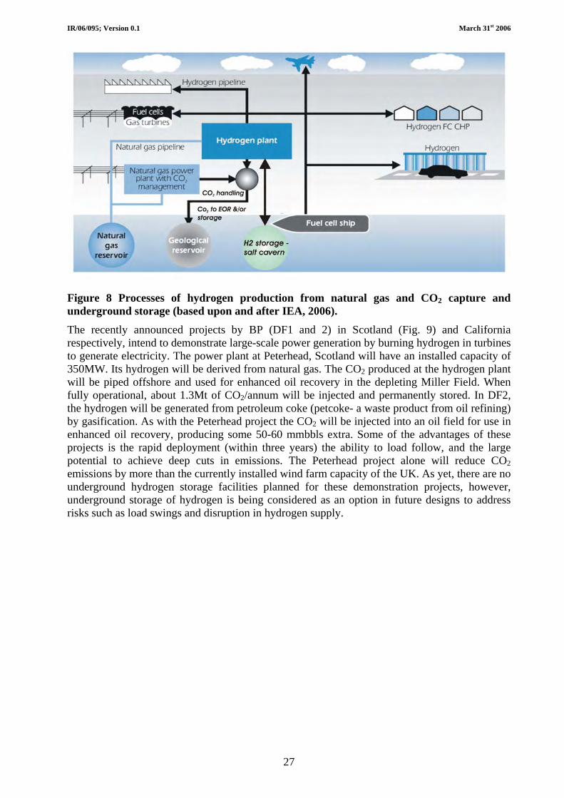
IR/06/095; Version 0.1 March 31st 2006
27
Figure 8 Processes of hydrogen production from natural gas and CO2 capture and underground storage (based upon and after IEA, 2006). The recently announced projects by BP (DF1 and 2) in Scotland (Fig. 9) and California respectively, intend to demonstrate large-scale power generation by burning hydrogen in turbines to generate electricity. The power plant at Peterhead, Scotland will have an installed capacity of 350MW. Its hydrogen will be derived from natural gas. The CO2 produced at the hydrogen plant will be piped offshore and used for enhanced oil recovery in the depleting Miller Field. When fully operational, about 1.3Mt of CO2/annum will be injected and permanently stored. In DF2, the hydrogen will be generated from petroleum coke (petcoke- a waste product from oil refining) by gasification. As with the Peterhead project the CO2 will be injected into an oil field for use in enhanced oil recovery, producing some 50-60 mmbbls extra. Some of the advantages of these projects is the rapid deployment (within three years) the ability to load follow, and the large potential to achieve deep cuts in emissions. The Peterhead project alone will reduce CO2 emissions by more than the currently installed wind farm capacity of the UK. As yet, there are no underground hydrogen storage facilities planned for these demonstration projects, however, underground storage of hydrogen is being considered as an option in future designs to address risks such as load swings and disruption in hydrogen supply.

IR/06/095; Version 0.1 March 31st 2006
28
Figure 9 Schematic of the BP Peterhead hydrogen production and use, CO2 storage and enhanced oil recovery project (courtesy of BP).
5.4.1.2 RENEWABLE ENERGY AND HYDROGEN PRODUCTION
Numerous ways exist for producing hydrogen from renewable energy sources (DTI, 2005; http://www.dti.gov.uk/renewables/renew_1.6.1.htm), including from a variety of biomass (cellulose) feedstocks, such as agricultural crops and wastes, sewage sludge or municipal solid waste, by thermochemical (pyrolysis or gasification) or biological processes that break down complex organic molecules into simpler molecules including hydrogen.
Hydrogen can, via electrolysis, also be produced from electricity, by splitting water into hydrogen and oxygen (however it should be noted that electrolysis of sea water will produce toxic bi-products such as chlorine and caustic soda). The electricity can be generated from renewable sources such as wind, tide or solar. In this way, therefore, it would be possible to produce electrolytic hydrogen in most parts of the UK, providing a way of storing renewably generated electricity on a much larger scale than is currently possible with existing battery technology.
The stored hydrogen can be converted back to electrical energy when renewable sources are not available due to intermittency. This would only make sense if the primary electrical generation from the renewable source could not be delivered straight to market or was in surplus, or if the electricity was going to be used for electrolysis regardless (e.g. in caustic soda/chlorine

IR/06/095; Version 0.1 March 31st 2006
29
production) as there is a large energy penalty associated with electrolysis. Existing electrolysers are not very efficient, resulting in a significant energy loss in the storage process and so raising the cost. With electrolysis of fresh water oxygen is a bi-product. If this oxygen can be used to displace oxygen produced cryogenically (the standard way that oxygen is supplied and very energy intensive) this would offset some of the energy penalty. Oxygen is necessary in integrated gasification combined cycle power plants, supplied via an air separation unit. Oxygen will also be required for future power plant designs using flue gas recycling. These apparent co-benefits between renewable energy, hydrogen and future fossil fuel power generation designs need further assessment.

IR/06/095; Version 0.1 March 31st 2006
30
6 Description of energy storage facilities operational in the UK and around the world.
6.1 UNDERGROUND THERMAL ENERGY STORAGE The following sections briefly review thermal underground energy storage scenarios, which cover a range of geological environments from aquifer to cavern or whole rock storage facilities.
6.1.1 Aquifer Thermal Energy Storage (ATES) ATES takes advantage of natural groundwater storage in the form of aquifers. There are two modes of operation, cyclic flow and continuous flow. In a cyclic flow regime two wells (or sets of wells) are drilled into the aquifer (Fig. 10). During periods of heat recharge (very often in the summer) warm water is injected and a warm reservoir is developed. During periods of abstraction the heat reservoir is exploited from the other well (or wells). In such a cyclic system both sets of wells must be designed to produce or to accept groundwater. In a continuous flow regime (Fig. 10) water is continuously pumped from one well. Usually, in summer, hot water is injected through the other well, whilst in winter cold water is injected. Hence this type of system is very similar to a ground source heat pump and the temperatures within the storage aquifer will be close to ground temperatures.
The efficiency of a thermal store is measured by the percentage of heat recovered, which depends upon minimising heat losses and the length of time that the heat is stored. The important parameters for ATES are medium to high hydraulic conductivity and transmissivity, high porosity and little or no groundwater flow. Examples are porous aquifers in sandstone and fractured aquifers in chalk and limestone.
Figure 10 Basic principles of aquifer thermal energy storage

IR/06/095; Version 0.1 March 31st 2006
31
6.1.2 Borehole Thermal Energy Storage (BTES) In a BTES system an array of boreholes are drilled into the ground to a maximum depth of around 100 m. A U shaped pipe runs up and down the borehole so that heat is exchanged between the fluid in the pipe, usually water, and the surrounding rock mass. During periods of heat recharge warm water is pumped through the pipes and the rock mass heats up to produce a heat reservoir. During periods of heat abstraction cold water is pumped through the same boreholes to exploit the stored heat. Hence BTES systems work in a cyclic mode. The efficiency of the heat exchange will improve with higher thermal conductivities, but the rate of heat conduction away from the reservoir (hence heat loss) will increase with higher thermal conductivities. Therefore the important parameters for BTES are medium thermal conductivities, high specific heat and no groundwater flow. Examples are low porosity sedimentary rocks such as shale, marl and clay and igneous rocks like basalt and granite.
6.1.3 Cavern Thermal Energy Storage (CTES) One other form of storage is to use natural or artificial caverns where hot water can be stored. Such systems are not common due to the unavailability of suitable caverns. The important parameters are for the rock to have low thermal conductivity, high stability and to be not leachable. Examples are metamorphic rocks like gneiss, igneous rocks and some hard sedimentary rocks.
6.1.4 Modelling and case histories If sufficient parameters are known for an intended UTES installation then it is possible to model the expected performance so that the design can be optimised. Two recent examples, both using finite element modelling, are given by Tenma et al. (2003) and Ucar and Inalli (2005). Tenma (2003) modelled a two well open system, whilst Ucar and Inalli (2005) modelled a system that used solar collectors connected to an underground storage tank.
There are no reports in the literature of installed UTES in the UK. However, Adams (1982) reported a small-scale experiment for an ATES system near Cambridge. The confined aquifer consisted of a 13 m thick section of Lower Greensand, underlain by Jurassic clay and overlain by 31.5 m of Gault Clay and 4 m of Chalk. A total of 1520 m3 of water was injected over a period of 78 days at a mean temperature of 57° C. A storage period of 105 days was followed by an abstraction period of 97 days. The percentage of injected heat recovered was only 32.5%. This low value was attributed to the relatively small injection volume, the small thickness of the aquifer and the length of the storage period compared to the injection and recovery periods. It was also likely that much of the lost heat energy was used in heating the aquifer matrix and so further injection cycles would have led to higher recovery.
There are many demonstration projects and a number of permanently running UTES systems in Europe. Three different types of successful UTES are briefly reviewed in order to demonstrate the potential of this technology.
6.1.4.1 REICHSTAG BUILDING, BERLIN
The new Reichstag building in Berlin has been equipped with an ATES system (Seibt and Kabus, 1997). Two wells, 300 m apart have been drilled to a depth of 320 m into a confined sandstone aquifer of Lower Jurassic age. The confining layer consists of shale and clay. The initial groundwater temperature was 19° C, but the heat storage temperature is 70° C. The building has two heat and power co-generation plants and the ATES is loaded in the summertime with excess heat from the co-generation. In the wintertime heat is unloaded directly to the heating system or, if the extraction temperature drops too low, to heat pumps.

IR/06/095; Version 0.1 March 31st 2006
32
6.1.4.2 NECKARSULM, GERMANY
At Neckarsulm in Germany a BTES system has been installed to collect solar thermal energy in the summer for use in the winter (Seiwald et al., 1999). The project is within a new residential area of 1300 flats and terraced houses. The solar collectors are placed on the roofs of the flats and houses and the intention is that 50% of the space and water heating will be met from solar. The BTES store consists of 528, 30 m deep boreholes, spaced 2.5 m apart accessing a ground volume of 63,360 m3. The geology of the site comprises Upper Triassic marls, with some dolomite overlain by loess of Quaternary age. The mean underground thermal conductivity is 2 W m-1 K-1 and the mean volumetric heat capacity is 3 MJ m-3 K-1. There is no heat pump in the system, but there are gas boilers to meet peak demand. Once the store is fully operational it is hoped that the heat recovery factor will be 75 to 80%.
6.1.4.3 LYCKEBO, UPPSALA, SWEDEN
A CTES system has been installed at Lyckebo in Uppsala, Sweden. Heat is supplied to a district heating system by a solar collector area of 4,320 m2. The system is designed to supply 550 families with space and water heating. Excess hot water from the summer is stored in an underground excavation of volume 100,000 m3. The cavern has a doughnut shape that has a high volume to perimeter surface ratio, thereby reducing heat loss. The water in the cavern is inserted and extracted by two telescopic pipes that helps to ensure a good temperature stratification with top and bottom temperatures of 90° C and 40° C respectively (Pilebro et al., 1986).
6.2 UK EXAMPLES OF GAS STORAGE IN DEPLETING OIL/GAS FIELDS The first gas storage experiment took place at a gasfield in Welland County, Ontario (Canada) in 1915. The first gas storage facility in a depleted hydrocarbon reservoir was built in 1916, using a gasfield in Zoar near Buffalo, New York (USA). By 1930, there were nine storage facilities in six different US states. Prior to 1950, virtually all natural gas storage facilities were in depleted reservoirs and today depleted reservoirs provide over 450 storage facilities world-wide.
6.2.1 Operational facilities in the UK The following are summaries of various oil or gas field gas storage facilities/operations in the UK.
6.2.1.1 ROUGH GASFIELD, SOUTHERN NORTH SEA
The Rough gasfield storage facility is about 31km (20 miles) off Withernsea on the East Yorkshire coast, in the southern North Sea. It was originally developed in October 1975 to produce natural gas from the Permian, Rotliegendes sandstone reservoir, at around 2750 m (circa 9,000 feet) below the seabed, forming the Rough field.
The gasfield was converted to Britain’s biggest offshore gas storage facility in 1985, since when it has been used to store gas under pressure in the depleted Rotliegendes reservoir, providing seasonal gas storage capability (Stuart, 1991). It is capable of supplying around 10 per cent of Britain's peak demand for gas and currently represents 80% of the UK’s gas storage volume. In November 2002, the Rough offshore gas storage facility and linked pipeline and onshore processing plant at Easington in Yorkshire was acquired by Centrica.
At approximately 10.30 in the morning of 16th February 2006, a severe fire broke out on the Bravo 3B platform of the gas storage facility. The fire led to the evacuation of thirty-one of the workers, including two who suffered burns and smoke inhalation and were treated in hospital. Twenty-five essential staff remained on the platform, whilst the fire was put out. Production on

IR/06/095; Version 0.1 March 31st 2006
33
both the Bravo and Alpha platforms was halted whilst the Bravo platform was depressurised and made operationally safe.
Rough is expected to come back into service in the summer of 2006 at an estimated repair cost of £40m. The shutdown caused wholesale prices to rise by 40 per cent, however, these quickly fell back again as more details of the incident emerged, easing fears. Details of the cause of the fire have not yet been released.
6.2.1.2 HATFIELD MOORS AND HATFIELD WEST
The Hatfield Moors gasfield was discovered accidentally (leading to a blow out and fire) during drilling of the Hatfield Moors No.1 exploration well in South Yorkshire in December 1981 (Ward et al., 2003). It was followed by the discovery of the small Hatfield West gasfield in 1983. Gas was encountered at a depth of 484 m (1587 feet) in the Westphalian B Oaks Rock Sandstone Formation. Gas was previously unknown at this stratigraphic level, apart from mine gas, despite the many coal and several oil boreholes that had already penetrated this shallow formation in this area.
Production at the fields commenced in 1986, with both presently 100 per cent owned and operated by Edinburgh Oil and Gas (EOG). Gas was initially supplied to the local Belton Brickworks, although this contract terminated in June 2000.
Devised in 1996, a plan was agreed with Scottish Power in 1998 to use the depleting Hatfield Moors field as a gas storage facility. A 25-year storage contract was agreed and the gasfield was converted to a gas storage facility during 2000. Under the agreement Scottish Power have exclusive rights to inject, store and withdraw gas. EOG receives revenues based upon the storage capacity of the reservoir and for the provision of reservoir management services to Scottish Power.
Although the technique is widely used in Germany and the US, Hatfield Moors represents the first onshore UK facility of its kind. Gas from the National Transmission System is compressed before being injected into the porous layers of sandstone circa 1,450 feet underground for storage. The reservoir can store up to 4.3 billion cubic feet (121.8 million m3) of gas at any one time, providing enough gas to meet the peak demands of 250,000 domestic customers. This enables Scottish Power to manage swings in demand and to buy additional gas to store when prices are lowest. It also helps the company to meet its obligations under the Network Code, which demands that gas suppliers must balance daily the amount of gas they put in and take out of Transco's Transmission System.
Some of the gas stored at Hatfield Moors is also used for electricity generation at Scottish Power’s gas-fired power stations. Before gas can be returned to the network for transportation to customer, it must be returned to the appropriate pressure. A 12 km pipeline provides the link between the storage facility and Transco's Gas Transmission System.
The Hatfield West field also has potential for conversion to use as a gas storage facility.
6.2.1.3 HUMBLY GROVE, HAMPSHIRE
The Humbly Grove oilfield in Hampshire was one of the largest onshore oilfields in the UK. However, as production declined, Star Energy proposed to develop it as a gas storage facility when they announced the major new underground gas storage scheme in early 2003 (received by Hampshire County Council, May 2003: www.hants.gov.uk/decisions/decisions-docs/030910-regunct-R0909111823.html). Having gained planning permission in 2003, work commenced on the site in February 2004 to construct a 10 billion cubic feet gas store (Fig. 11). The facility was completed in February 2005 and commenced operation on November 4th 2005. The gas injection will also re-pressurise the oil reservoir, thereby extending the life of the field from less than 10 years to around 20 years.

IR/06/095; Version 0.1 March 31st 2006
34
Figure 11 Humbly Grove gas storage facility (after Star Energy). a) site clearance (Feb 2004) and b and c) completed facility (Feb 2005). The facility required the construction of a pipeline 27 km long and 24 inches in diameter to link the oilfield to the national gas transmission system (NTS) at Barton Stacey near Andover. An additional processing plant has been constructed, together with the installation of compression equipment to pump the gas into the gas store from the NTS and to return the gas back to the NTS after processing.
6.2.1.4 KINSALE AREA GASFIELDS, OFFSHORE IRELAND
The Kinsale Area gasfields are located off Cork in the south of Ireland (Fig. 12). They comprise the Kinsale Head, Southwest Kinsale and Ballycotton Gas Fields and are owned and operated by Marathon. The Kinsale Head Gasfield was discovered in the Lower Cretaceous Greensand in 1971 and started production in 1978. The field is produced through two platforms, Alpha and Bravo, with Bravo production routed through the Alpha platform, co-mingled with the Alpha production and exported via a 24 inch pipeline to the onshore distribution system.
Figure 12 Map of the Kinsale area gasfields (after Marathon Oil).
a b c

IR/06/095; Version 0.1 March 31st 2006
35
However, the gasfield depleted and following preparatory work in 2000, the Kinsale Gasfield became Ireland’s first seasonal production facility in 2001, when the southwest lobe of the Kinsale Field was converted for gas storage. The depleting reservoir is recharged during the summer months, with gas re-produced and delivered to the market in the winter months, when demand is higher.
6.2.2 Planned facilities in the UK As detailed by DTI (2005), there are a number of planned storage facilities in England. Table 2 outlines the current status of these planned facilities, which are currently the subject of further studies or planning applications.
Table 2. Proposed gas storage facilities in depleted/depleting oil and gas fields onshore England (based upon DTI, 2005 – Secretary of State’s First Report to Parliament on Security of Gas and Electricity Supply in Great Britain, July 2005; Energy Review - DTI, 2006).
Facility name Capacity (mcm) Start Year Year to achieve total capacity
Planning status
Welton 435 2008 2009
Planning application not granted – likely Public Inquiry
Saltfleetby 600 2008 2008 Pre-planning
Bletchingly Up to 900 2009 2009 Pre-planning – drilling required
Albury – phase 1 160 2007/8 2007/8 Pre-planning
Albury– phase 2 Up to 715 2010 2010 Pre-planning – drilling required
Caythorpe 210 2007 2007 Pre-planning
6.2.2.1 WELTON, LINCOLNSHIRE
The Welton oilfield has been producing oil (and associated gas) since 1984 and is now reaching the mature stage of production as reservoir pressures and oil production decline.
The proposals involve the construction of a 24” diameter steel pipeline, mainly located underground, from an existing national gas pipeline system near Holton cum Beckering (to the north of Wragby) which will link to the existing Star Energy Gathering Centre to the northeast of Reepham, and southeast of Sudbrooke. At the Gathering Centre the gas will be pumped into the existing depleted underground oil reservoir during periods of low gas demand, where under pressure it will assist in the recovery of the residual oil resources, but will also act as a substantial gas storage facility (see Table 2). The stored gas will be reintroduced back into the national system during periods of high demand.
West Lindsey District Council at an Extraordinary Meeting of the Council on 27th May 2004 resolved to recommend “that Lincolnshire County Council be strongly urged not to grant planning permission”, citing public safety fears as the main point of concern. Subsequently, County council planners recommended planning permission be granted for the proposal, subject to certain conditions, and neither the Environment Agency, nor English Nature or the Health and

IR/06/095; Version 0.1 March 31st 2006
36
Safety Executive had major concerns over the project. However, at a meeting on 22nd February 2006, Lincolnshire County planning committee concluded that planning application “was minded to be refused”, citing local fears over health and safety and claiming the proposals would represent an intensification of industrial development in open countryside, which was contrary to planning policy. The recommendation was that the proposal be called in for consideration and determination only after a Public Inquiry.
Star Energy immediately stated that they will appeal the decision to the Office of the Deputy Prime Minister believing that the company has solid grounds for appeal due to the fact the council's planning officers' report recommended approval of the project. It seems likely, therefore, that the situation will be resolved at a Public Inquiry at some point in the future.
6.3 WORLDWIDE EXAMPLES OF AQUIFER STORAGE Currently, the UK has no aquifer storage capabilities proposals having only been received for depleted oil/gasfields and salt cavern facilities.
Aquifers for gas storage were first used in 1946 in Kentucky (United States). Today, there are over 76 such storage facilities in aquifers (Chabriele et al., 2003), most of them in the United States and the former Soviet Union. There are around 23 aquifer storage sites in NW Europe (Fig. 13), the majority of which are in France, where 12 such facilities are in operation.
Lussagnet & Izaute
Chemery, Soings & Cere-le-Ronde
Figure 13 Distribution of gas aquifer storage facilities in Northwest Europe (after Gasunie).
6.3.1.1 LUSSAGNET/IZAUTE, SW FRANCE
Total wholly own and operate two aquifer storage facilities at Lussagnet and Izaute in SW France (Fig. 14). Both are constructed in Eocene sands with capacities of 2.4 bcm and 2.8 bcm respectively. Both are formed where the aquifer is affected by shallow anticlines.

IR/06/095; Version 0.1 March 31st 2006
37
Figure 14 Sketch cross section illustrating the setting of the Lussagnet aquifer storage facility in SW France (after Gourlia, 2006).
6.3.1.2 STENLILLE, DENMARK
An aquifer gas storage facility was established in 1989 at Stenlille (Figs 15 and 16), approximately 70 km SW of Copenhagen in Denmark (Laier and Øbro, 2004 and in press).
Figure 15 Map and sketch showing the location and style of the Stenlille aquifer storage site in Denmark (after Laier and Øbro, 2004).
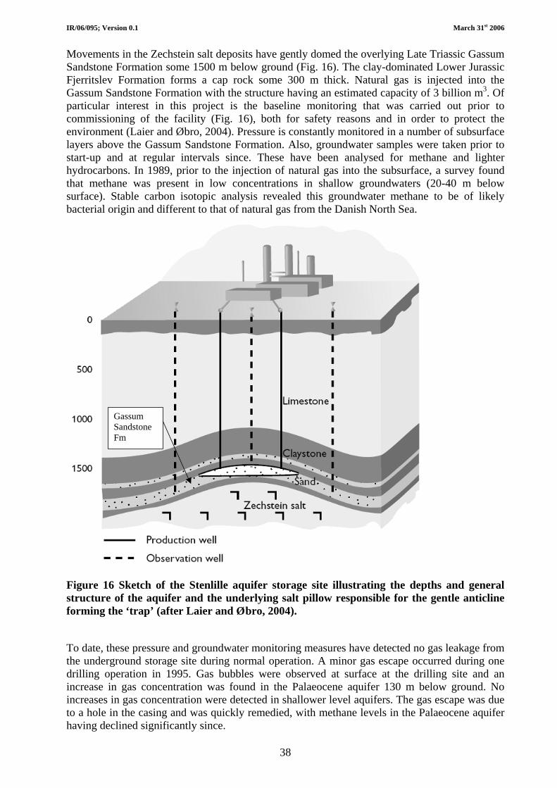
IR/06/095; Version 0.1 March 31st 2006
38
Movements in the Zechstein salt deposits have gently domed the overlying Late Triassic Gassum Sandstone Formation some 1500 m below ground (Fig. 16). The clay-dominated Lower Jurassic Fjerritslev Formation forms a cap rock some 300 m thick. Natural gas is injected into the Gassum Sandstone Formation with the structure having an estimated capacity of 3 billion m3. Of particular interest in this project is the baseline monitoring that was carried out prior to commissioning of the facility (Fig. 16), both for safety reasons and in order to protect the environment (Laier and Øbro, 2004). Pressure is constantly monitored in a number of subsurface layers above the Gassum Sandstone Formation. Also, groundwater samples were taken prior to start-up and at regular intervals since. These have been analysed for methane and lighter hydrocarbons. In 1989, prior to the injection of natural gas into the subsurface, a survey found that methane was present in low concentrations in shallow groundwaters (20-40 m below surface). Stable carbon isotopic analysis revealed this groundwater methane to be of likely bacterial origin and different to that of natural gas from the Danish North Sea.
Gassum Sandstone Fm
Figure 16 Sketch of the Stenlille aquifer storage site illustrating the depths and general structure of the aquifer and the underlying salt pillow responsible for the gentle anticline forming the ‘trap’ (after Laier and Øbro, 2004).
To date, these pressure and groundwater monitoring measures have detected no gas leakage from the underground storage site during normal operation. A minor gas escape occurred during one drilling operation in 1995. Gas bubbles were observed at surface at the drilling site and an increase in gas concentration was found in the Palaeocene aquifer 130 m below ground. No increases in gas concentration were detected in shallower level aquifers. The gas escape was due to a hole in the casing and was quickly remedied, with methane levels in the Palaeocene aquifer having declined significantly since.

IR/06/095; Version 0.1 March 31st 2006
39
6.4 EXAMPLES OF STORAGE OF DIFFERENT TYPES OF ENERGY IN SALT CAVERNS AND OTHER GEOLOGICAL ENVIRONMENTS
As alluded to above, salt cavern storage can potentially play a significant role in the underground storage of natural gas, liquid hydrocarbons and hydrogen. It also plays a role, which might be expected to increase with time, in compressed air storage.
The following sections briefly review underground energy storage scenarios in salt caverns with regard to potential in the UK and Northern Ireland in particular, and is illustrated by examples from the UK and around the world.
6.4.1 Hydrogen storage Hydrogen is a gas at ambient temperatures and pressures, but it can be stored as a gas, a liquid or a solid. In the case of hydrogen, underground (geological) storage provides the greatest volumes and is considered in this report. Solid storage, whereby hydrogen exists as a chemical compound, and not as a pure substance is not considered here.
Compressed gaseous hydrogen represents a mature technology, whereby stationary storage above ground is common, being best suited for frequent turn-over. However, underground geological storage provides greater volumes and potentially represents the cheapest option for longer term storage. In the Tees Valley, UK, bedded salt deposits near Middlesbrough in the north east of England have been used to store 1,000 tonnes of hydrogen for industrial use for over 25 years (BGS, 2004; Beutal and Black, 2005).
6.4.1.1 TEES VALLEY HYDROGEN PROJECT AND RENEWABLE ENERGIES
The Tees Valley Hydrogen Project in the north east of England was established to assist in bringing new energy technologies from development to operation. The region has a strong technological base and local experience in hydrogen handling, which greatly influenced the concept and creation of the project.
The Tees Valley has a 30 km hydrogen distribution system incorporating an underground hydrogen storage facility, located within an urban environment (Fig. 17). It capitalises on some of the assets created over the years by, in the main by ICI, in the Tees Valley. The purpose is to develop technologies into commercially viable operations and complements the areas policy on renewable energy schemes.
From the existing infrastructure, Renew Tees Valley Ltd was established by local Councils to support a range of projects currently being discussed with potential investors. These include Wind Hydrogen Limited, and will, among other things, seek to capitalise on the Tees Valley's pioneering work in the development and application of hydrogen fuel cells. The work will utilize technologies to balance out and smooth the peaks and troughs associated with wind energy and the generation of hydrogen via electrolysis.

IR/06/095; Version 0.1 March 31st 2006
40
Hydrogen Project
Infrastructure• Underground storage cavities• Pipelines running through population centres and under the river
• Large hydrogen generation plants
Figure 17 Tees Valley hydrogen infrastructure (after University of Salford).
6.4.2 Compressed air (CAS) and compressed air energy storage (CAES) Research into CAS and CAES is ongoing around the world, with plans to construct a number of CAES plants that will utilise aquifers and former mines. Italy has operated a small 25 MW CAES research facility based on aquifer storage, whilst Israel has conducted research in to building a 3x100 MW CAES facility using hard rock aquifers (Cheung et al., 2003).
The main disadvantage of CAES is the identification and location of suitable geological structures or sequences, whereas the advantages of a CAES plant are that:
• Can be used on very large scales – no other storage method provides the capacities possible with CAES
• Long storage periods – losses are small
• Fast start up times compared to conventional combustion turbines
• No large costly above ground installations in addition to the power plant
• Emission of greenhouse gases significantly lower than normal gas plants
The following sections outline the existing facilities.
6.4.2.1 HUNTORF, GERMANY
The Huntorf plant (Fig. 18), situated in north Germany, was developed in 1978 as the world’s first CAES plant, using two 150 m high salt caverns (referred to as NK1 and NK2) constructed in the Huntorf salt dome at depths between 650 m and 800m. Their maximum diameters are 60

IR/06/095; Version 0.1 March 31st 2006
41
m, with the wells spaced at 220 m. The depths permit operating pressures between 43 and 70 bar (although in exceptional circumstances, minimum operational of 20 bar are possible).
Figure 18 Aerial view of the Huntorf CAES plant (photograph after Crotogino et al., 2001).
The Huntorf plant has run reliably on a daily cycle for over 27 years, having completed 7000 starts that involve charging over an eight-hour period, then delivering 300 megawatts for 2 hours of discharge (Crotogino et al., 2001; Cheung et al., 2003).
6.4.2.2 MCINTOSH, ALABAMA, USA
As mentioned above, the McIntosh facility is the first CAES plant in the USA (Fig. 19) and is constructed in the McIntosh salt dome, Alabama (Leith, 2001). Alabama Electric Cooperative's (AEC's) generating units at McIntosh, Alabama, include the compressed air energy storage (CAES) unit and twin gas-fired combustion turbines.
The CAES unit (designated McIntosh unit 1), was declared commercial May 31st 1991, and officially fully operational September 27th 1991. In the generation process, the 100-megawatt CAES unit uses air compressed and stored in a 20,000,000 ft3 underground cavern. When the compressed air is needed for generation, it is mixed with natural gas in a convention gas turbine combustion process to generate electricity. The plant uses off-peak electricity to pump air into the cavern, then uses the air in the generation process during peak periods.
In June 1998, contractors completed work on two single-cycle combustion turbines at the McIntosh site. The units have a generation capacity of 226 megawatts, and are designed as McIntosh units 2 and 3. While these units are not CAES units, they have increased the total power generation capacity of the McIntosh facility to over 326 megawatts.

IR/06/095; Version 0.1 March 31st 2006
42
Figure 19 The McIntosh CAES plant, Alabama (photograph after Haug, 2005)
The top of the 275 m high solution-mined salt cavern is at 457 m (1,500 ft) below ground level, with the bottom of cavern at 732 m (2,400 ft). The cavern is circa 76 m in diameter and provides approximately 315,000 m3 (19-million-ft3) air storage (Leith, 2001). At full charge, air pressure is 76 bar (1,100 psi), whilst at full discharge, cavern air pressure is 45bar (650 psi).
6.4.2.3 NORTON, OHIO
In 2001, Ohio Power Siting Board approved the Norton Energy Storage (a subsidiary of Haddington Ventures) application for a certificate of environmental compatibility and public need to develop a CAES plant in an old limestone mine 670 m (2200 ft) below ground. This development is located on a brownfield site within the city limits of Norton, about 35 miles south of Cleveland, Ohio.
Commercial operation was estimated to begin in 2003 and to be fully operational by 2008. The development plan involves the installation of nine 300 MW Alstom ET11NM turbines, capable of ultimately producing 2,700 MW of electricity, serving over 675,000 homes. When fully operational, it is claimed that the plant will only produce the same amount of emissions as a 600-megawatt gas-powered combustion turbine power plant.
The facility will compress air using off-peak electricity and store it in an underground limestone mine (Fig. 20). The mine was originally operated by the Pittsburgh Plate Glass Company between 1943 and 1976, producing the synthetic soda ash used in the manufacture of glass. The mine covers an area about 2130 m by 1220 m (7,000 ft by 4,000 ft, or 643 acres) and is built in a room and pillar mine configuration -- rooms separated by pillars, leaving 338 million cubic feet of space. Although well below the water table, the mine is said to be virtually dry.
In situ and laboratory tests determined the permeability and integrity of the limestone and overlying shales and their capability to withstand pressure cycling. The limestone is a dense rock with few fractures, tests revealing it is capable of withstanding the planned operating pressure

IR/06/095; Version 0.1 March 31st 2006
43
range of 55-110bar (800 to 1,600 psi). Flow analyses and modelling indicated that pressurized air will move less than 30 m (100 ft) away from the mine in 50 years and will have no effect on the air compression and decompression cycling.
Construction will include two large concrete plugs closing off the two entrances of the mine, with layers of clay and tar within the concrete preventing leakage. Two boreholes, roughly two feet in diameter, will be drilled, acting as valves for injecting and bleeding out the air.
Figure 20 Diagrammatic representation of the proposed Norton CAES plant at Norton, Ohio (after Sandia and CAES Development Company LLC).
6.4.2.4 IOWA STORED ENERGY PLANT
In 2003, it was planned to build the Iowa stored energy plant, which would be the first plant to use wind energy, as well as off-peak electricity to compress the air and store it in an underground aquifer (Haug, 2005). When generation is needed, the compressed air would be released to drive natural gas-fired combustion turbines. The proposal included building a wind farm, using 1.5-MW wind turbines.
Located near Fort Dodge, Iowa close to the electric transmission grid and a gas pipeline, the aquifer is Palaeozoic in age (Fig 21), which, during the 1960s was originally developed by Northern Natural Gas for natural gas storage. Part of the new facility could still be used to store natural gas indicating that the aquifer remains stable and with an effective seal. However, following further investigations, the geology may not be as favourable as was originally thought (Holst, 2005).

IR/06/095; Version 0.1 March 31st 2006
44
Figure 21 Diagrammatic representation of the Iowa CAES scheme (after Holst, 2005).
6.4.3 Natural gas Salt cavern storage can potentially play a significant role in the underground storage of natural gas, but such facilities can also be employed to store liquid hydrocarbons. The main use of salt cavern storage lies in the USA, where extensive salt deposits of Permian and Jurassic age are found. The Gulf Coast of Mexico has many cavern facilities developed in salt domes. In Europe, France and Germany also have cavern storage facilities and others are being developed in Denmark and England.
6.4.3.1 SALT CAVERN GAS STORAGE FACILITIES IN THE UK
Table 3 outlines the various underground salt cavern gas storage facilities either currently operational or planned in the UK (BGS, 2004; Beutal and Black, 2005). They fall into two categories, being dependant upon whether they are in salt of Triassic or Permian age.
6.4.4 Lined Rock Caverns As described above, lined rock cavern (LRC) technology aims to provide storage capacities for countries where the lack of suitable geological formations (e.g. crystalline and metamorphic rocks) precludes any other form of underground storage facility. This may be for gas but could also include another form of thermal energy storage (Cavern Thermal Energy Storage - CTES), where hot water can be stored in natural or artificial caverns. Such systems are not common due to the unavailability of suitable caverns. The important parameters are for the rock to have low thermal conductivity, high stability and to be not leachable, examples being metamorphic rocks like gneiss, igneous rocks and some hard sedimentary rocks.

IR/06/095; Version 0.1 March 31st 2006
45
Table 3. Existing and planned salt cavern storage as of March 2006.
Area Site Owner/Operator Approx. cavern
depth (top-bottom if known)
Nos. of caverns
Storage Capacity (Mcm)
Planning stage Comments
Hornsea - Atwick Scottish and Southern Energy 1730-1830 m 9 325 Granted 1973 Operating since 1979
Saltholm, Teesside ICI 350-420 m >100 Not known Not known Leached volumes in range 10,000 m3 - 100,000 m3
Wilton, Teesside ICI c. 650 m 3? Not known Not known Cavities leached solely for storage of ethylene, butane and nitrogen
Hornsea – Aldborough north & south
Scottish and Southern Energyand Statoil
1800-1900 m 9 420 Granted 2000 2 sites, operational by end 2007?
East Yorkshire (Permian salt)
Saltholm (Teesside) Ineos/ Chlor/ Huntsman 340-370 m 4 160 Not known Converted ICI caverns
Holford, H-165 Ineos/ Chlor (formerlyoperated by NG [Transco])
350-420 m 1 0.175 Granted 1983. Ten year inspection completed 2006
Abandoned brine cavities. Ethylene & natural gas storage since 1984
Holford/ Byley
(southern end of Holford brinefield - Drakelow Lane
area)
Scheme initiated by ScottishPower, sold to E.On UK Plc.Salt caverns to be leased fromIneos who own salt & willconstruct caverns
630-730 m 8 160-170 Granted 2004 Secretary of State reversed Inquiry decision. Under construction
Hole House Farm Energy Merchant (EDF Trading)
300-400 m 4 60-75 Granted 1995 Commenced operations in Feb 2001
Cheshire (Triassic salt)
Stublach
Holford brinefield between Drakelow Lane and Lach
Dennis
Ineos Enterprises Ltd 550-650 m 28 540 Planning application Dec 2005, granted June 2006
Government will not call in for Inquiry. Project progressing to design stage,
commissioning 2009?
NW England(Triassic salt)
Preesall Canatxx Gas Storage Limited 245–510 m 24 c. 12001 Public Inquiry (late 05-early 06)
Significant public objection to proposals
Dorset (Triassic salt) Portland Portland Gas Limited (subsid.
Egdon Resources) 2100-2300 m 18 9902 In pre-planning stage 2006 3 phases, each with 6 caverns
1 Note: DTI (2006e&f) figure 2 Note: DTI (2006e&f) quotes up to 1.7 bcm (1700 Mcm)

IR/06/095; Version 0.1 March 31st 2006
46
6.4.4.1 GRANGESBERG PILOT PLANT, SWEDEN
This facility was built in 1988 and is situated approximately 250 km west of Stockholm. Between 1988 and 1993, there were a number of developmental stages, which led to a number of ‘caverns’ being constructed. They were generally in the order of 9 m in height, 4.4 m wide with volumes of 120-130 m3 at a depth of 50 m (Chabrelie et al., 2003).
Each ‘cavern’ had an internal steel lining (to provide gas tightness) with an external concrete lining, providing smooth and even distribution of pressure transfer and deformation.
6.4.4.2 SKALLEN, HALMSTAD, SWEDEN
This was built and brought into service as a demonstration plant in 2001. It comprises storage caverns circa 100-150 m below ground level that can be accessed via tunnels from the side (Fig. 22). Each ‘cavern’ would typically provide or operate at:
• Geometrical Volume 40 000 m3 • Diameter 35 m (115 ft)
• Height 50 m (160 ft)
• Gas Pressure 200 bar (2900 psi)
• Total Gas Volume 10x106 m3 (360 MMcf)
• Working Gas Volume 8.5x10⁶ m3 (300 MMcf)
• Base Gase Volume 1.5x10⁶ m3 (60 MMcf)
Figure 22 Sketch diagram of the Skallen LRC demonstration plant in Sweden (after Vasques and Tengborg, 2001)

IR/06/095; Version 0.1 March 31st 2006
47
7 Outline of the geology of Northern Ireland On a global scale Northern Ireland represents only a tiny fraction of the land area of planet Earth but presents an almost unparalleled variety of geology in such a small area (Fig. 23). The following describes the geology of the onshore and offshore areas of Northern Ireland and identifies the sequences and areas that are most applicable to the search for sites suitable for the underground storage of energy.
Figure 23 Simplified geological map of Northern Ireland. (after Mitchell, 2004)
7.1 ONSHORE GEOLOGY The stratigraphical record of the rocks present in Northern Ireland commences in the Mesoproterozoic and includes representatives in all of the systems up to and including the Palaeogene, with the possible exception of the Cambrian (Table 4).

IR/06/095; Version 0.1 March 31st 2006
48
Table 4 Geological succession of the rocks in Northern Ireland.
ERA SYSTEM AGE
(million years)
LITHOSTRATIGRAPHY
NEOGENE 2-24 No Rocks
CAINOZOIC PALAEOGENE 24-65
Lough Neagh Group
Antrim Lava Group
CRETACEOUS 65-144 Ulster White Limestone Formation (Chalk)
Hibernian Greensands Formation
JURASSIC 144-205 Waterloo Mudstone Formation MESOZOIC
TRIASSIC 205-248
Penarth Group
Mercia Mudstone Group (includes salt beds)
Sherwood Sandstone Group
PERMIAN 248-290 Belfast Group (includes salt beds)
Enler Group
CARBONIFEROUS 290-354
Slievebane/Coal Measures Group
Millstone Grit Group
Leitrim/Kilskeery groups, Greenan Sandstone Formation, Tyrone/Armagh/Ballycastle/Strangford groups, Carlingford Limestone Group, Owenkillew Sandstone Group, Roe Valley/Holywood/Omagh Sandstone groups
DEVONIAN 354-417
Red Arch Formation
Cross Slieve Group
Fintona Group
SILURIAN 417-442 Hawick Group Gala Group
ORDOVICIAN 442-489
Leadhills Supergroup
Tyrone Igneous Complex comprising Tyrone Plutonic Group, Tyrone Volcanic Group and plutonic igneous intrusions
PALAEOZOIC
CAMBRIAN 489-545 No Rocks
NEO- 545-600 Dalradian Supergroup comprising
Southern Highland Group and Argyll Group PROTEROZOIC
MESO- >600 Moine Supergroup comprising Lough Derg Group and Corvanaghan Formation
7.1.1 Basement The basement geology of Northern Ireland represents those rocks older than the cover of late Palaeozoic and younger rocks. It is partitioned into three areas, with a NE-SW orientation, that are the remnants of major terranes (Fig. 24).

IR/06/095; Version 0.1 March 31st 2006
49
Figure 24 Configuration of basement terranes in Northern Ireland. (after Mitchell, 2004)
a) The northern terrane is composed of the oldest, metamorphic, rocks in Northern Ireland. These include the Mesoproterozoic Moine Supergroup and the Meso-Neoproterozoic Dalradian Supergroup (Table 4). Rocks of the Dalradian Supergroup form the Sperrin Mountains and are also exposed in northeast Co. Antrim. They consist of deformed and metamorphosed sedimentary and volcanic rocks. Prior to orogenesis the sedimentary rocks consisted of interbedded sandstone, siltstone, mudstone and limestone. However, repeated episodes of folding and faulting, accompanied by recrystallisation of the constituent minerals of the original sedimentary rock, led to the formation of new metamorphic mineral assemblages and rock types in which the original bedding was largely destroyed and was replaced by new planar fabrics, of several generations, that penetrate the entire rock mass.
b) Basement rocks of the central terrane are exposed in Co. Tyrone as the Mesoproterozoic Corvanaghan Formation and the early Ordovician Tyrone Igneous Complex. The Corvanaghan Formation occurs in the core of the Tyrone Igneous Complex and is represented by metamorphic rocks that probably originated as a sliver of the northern terrane. The surrounding Tyrone Igneous Complex is divided into three parts. In the southeast of the complex, the Tyrone Plutonic Group consists of igneous rocks including gabbro, basalt and dolerite representing oceanic crust upon which later sediment was deposited. The upper part of the complex comprises the Tyrone Volcanic Group and is formed of pillow lavas and volcaniclastic tuffs, lavas and chert, representing a volcanic arc sequence. Both the Corvanaghan Formation and Tyrone Igneous Complex are intruded by at least seven plutonic and higher level igneous intrusions of granite and tonalite.
c) In Counties Down and Armagh, in the southeast of Northern Ireland, the southern terrane is composed of Ordovician and Silurian marine sedimentary rocks of the Leadhills Supergroup

IR/06/095; Version 0.1 March 31st 2006
50
and the Gala and Hawick groups (Table 4), disposed in an accretionary prism. The terrane is segmented into tracts by major strike-parallel faults, typically spaced at between 1 and 5km. The succession within each tract is formed mainly of a well-bedded turbidite sequence consisting of greywacke sandstone, siltstone and mudstone. Throughout the terrane the beds strike NE-SW with an almost uniformly steep dip. A well-developed slaty cleavage is present in the mudstones and locally penetrates the fine-grained greywacke sandstone. Up to two crenulation cleavages formed during later deformations appear to be non-penetrative. Many small faults and later brittle fractures, in particular joints, with variable orientation are developed in all outcrops.
When the younger Phanerozoic cover rocks are superimposed on the three basement terranes it is evident that Northern Ireland can be divided into four areas with quite distinct geological characteristics and ages of rocks that are not usually found in any of the other quadrants (Figs 24 and 25, and Table 4).
Figure 25 Geological divisions of Northern Ireland (after Mitchell, 2004)

IR/06/095; Version 0.1 March 31st 2006
51
1) The northwest quadrant is composed of metamorphic rocks of the Dalradian Supergroup of the northern terrane and the Tyrone Igneous Complex of the central terrane.
2) The southeast quadrant is composed of Ordovician and Silurian rocks of the southern terrane with Devonian and Palaeogene intrusive complexes.
3) The southwest quadrant is composed largely of Carboniferous and Devonian rocks.
4) The northeast quadrant predominantly comprises the area of the Antrim Plateau and is composed at surface of Palaeogene basalt lavas of the Antrim Lava Group and lacustrine sedimentary rocks of the Lough Neagh Group, underlain by rocks of Permian to Cretaceous age.
In the southern part of the southern terrane, the late Palaeozoic Newry Igneous Complex is a late orogenic granite intrusion over 40km long and about 10km wide, intruded into Silurian greywacke and mudstone (Fig. 23). The complex is divided into three separate overlapping plutons, composed of fine-grained biotite granodiorite. A steeply inclined mineral foliation is developed at the margins of all the plutons but is not apparent in their centres. Silurian host rocks are thermally metamorphosed to hornfels at the margins of the plutons for up to 1 kilometre from the contact.
7.1.2 Late Palaeozoic to Palaeogene ‘cover’ Devonian rocks of the Fintona Group are confined in Northern Ireland to Counties Tyrone and Fermanagh where their outcrop is divided into two parts by major NE-SW faults. North of the Killadeas-Seskinore Fault the rocks consist entirely of red-bed sediments and are dominated by thick-bedded sandstone with minor siltstone, mudstone and palaeosol horizons. South of the Tempo-Sixmilecross Fault (Fig. 23) the sequence consists of coarse- to fine-grained sandstone with thin siltstone and mudstone and a very thick volcaniclastic conglomerate associated with trachy-andesitic lavas.
The cumulative thickness of 7000m of Carboniferous rocks is represented largely by the Lower Carboniferous (Tournaisian, Viséan and early Namurian) Tyrone Group in Co. Fermanagh, the early Carboniferous Kilskeery Group, late Carboniferous Slievebane Group and the Owenkillew Sandstone Group in the isolated basin at Newtownstewart. The Tyrone Group consists of 2500m of sandstone, mudstone and limestone formations and has been the focus of exploration for hydrocarbons. All Carboniferous rocks of the Kilskeery and Slievebane groups and the Greenan Sandstone Formation are red-beds and consist mainly of sandstone and thick conglomerates. With the exception of the isolated outcrop of Carboniferous rocks near Ballycastle in northeast Co. Antrim, there is little evidence to indicate their presence at depth beneath the Antrim Plateau.
The present distribution of virtually all post-Carboniferous rocks in Northern Ireland is restricted to the northeast quadrant. While the surface rocks of the Antrim Plateau (Fig. 23) are composed largely of Palaeogene basalt lava, the underlying Permian, Triassic, Jurassic and Cretaceous rocks (Table 4) are only exposed in a narrow outcrop at the margins of the plateau.
The outcrop of Permian rocks in Northern Ireland is restricted to small, isolated, areas in Counties Armagh, Down and Tyrone where the exposed thickness of strata is in the order of 20-40m. However, in contrast, the discovery of very thick concealed sequences of Permian rocks in deep boreholes, drilled particularly on the Antrim Plateau, has demonstrated the existence of contemporaneous, discrete, fault-bounded, basins separated by areas of higher ground on which the thin sequences developed. At the few known exposures, and in the case of almost all deep boreholes, the defining evidence for the presence of Permian strata is the presence of the Magnesian Limestone at the base of the Belfast Group (Table 4), which also provides a precise correlation between the exposed and concealed rocks. The Magnesian Limestone was deposited during a marine transgression and marks the change from the rocks of the Early Permian Enler

IR/06/095; Version 0.1 March 31st 2006
52
Group which were deposited primarily in an arid, hot, desert land environment, to those of the Late Permian Belfast Group which were deposited primarily in a shallow marine environment. The presence of a thick Late Permian salt bed in a deep borehole at Larne indicates deposition in a restricted subsiding marine basin under conditions of high evaporation rates. In Northern Ireland sedimentation appears to have been continuous from the Permian into the Triassic and might even extend through the Triassic and into the Jurassic.
In the Triassic, the Sherwood Sandstone Group consists of red sandstone and mudstone that was deposited by rivers or accumulated as sand dunes with little evidence of a marine connection. The succeeding Mercia Mudstone Group can be divided into lower and middle parts with halite (salt) beds, indicating an arid environment with frequent marine connections, and an upper, anhydritic part reflecting an arid, desiccated coastal plain. Beneath the basalt lavas of the Antrim Plateau, the combined thickness of the Sherwood Sandstone and Mercia Mudstone groups may be as much as 1500m. Although Triassic rocks are exposed around the entire margin of the Antrim Plateau, detailed information on their relative ages, lithostratigraphy and physical properties is only known from deep boreholes. The conformable Triassic-Jurassic boundary in Northern Ireland coincides with the change from a hot desert environment to a warm tropical marine environment.
The important sequences and rock properties of Permian and Triassic rocks having potential for gas storage are described in further detail below (section 7.2).
The Early Jurassic Waterloo Mudstone Formation (Table 4) is represented by a thin succession of grey mudstones with nodular limestone. These lithologies are only exposed at the margins of the Antrim Plateau below precipitous cliffs of chalk and basalt and cause landslips and instability in those areas.
The outcrop of Cretaceous rocks is located at the margins of the Antrim Plateau, primarily in Counties Antrim and Londonderry, although the chalk is almost always encountered in boreholes that penetrate the base of the basalt lavas. At the base of the sequence the Hibernian Greensands Formation comprises about 30m of sandstone with minor siltstone and mudstone. This is succeeded by up to 133m of very hard, white chalk, the Ulster White Limestone Formation, although this thickness is never exposed in one section. The greensand and chalk are significant sources of groundwater for public supply.
In Palaeogene times, Northern Ireland was part of the North Atlantic Igneous Province. Voluminous amounts of basalt lava of the Antrim Lava Group (Table 4) were produced by volcanic activity at that time. Those lavas now form the Antrim Plateau and are responsible for protecting the underlying rocks from erosion. The lavas are sub-divided into the Lower Basalt and Upper Basalt formations, with a total thickness of about 800m, separated by a thin Interbasaltic Formation. Individual lava flows in both formations are in the order of 10m thick and may be divided into a flow base, with concentrations of zeolite-filled vesicles, a central portion of massive fresh lava, often with irregular columnar jointing, and an upper part which is commonly weathered to purplish red lithomarge. Minor intrusions, particularly dykes, intrude all older rocks in Northern Ireland and are related to the extrusion of the basalt lavas.
Palaeogene intrusive igneous rocks form separate areas of mountainous terrain at Slieve Gullion and in the Mourne Mountains (Fig. 23). The Mourne Mountains Granite Complex is intruded into the Silurian Hawick Group and has a wide aureole of thermally metamorphosed greywacke and slate. The complex consists of five principal granite intrusions divided between a western and an eastern centre. Deep excavations through the plutons have revealed the presence of numerous Palaeogene dykes intruding the granite. The Slieve Gullion Complex consists of three distinct units and represents the ‘root’ zone of a deeply eroded volcano that intruded the southwest end of the Newry Igneous Complex. The earliest intrusion of felsic magma forms an almost complete ring, the Slieve Gullion Ring Dyke. In the centre of the intrusion, forming Slieve Gullion, is a later sheeted complex of flat-lying felsic and mafic layers. The final phase is a granite stock that is confined to the southeast part of the complex.

IR/06/095; Version 0.1 March 31st 2006
53
The final events in the geological history of Northern Ireland are related to the formation of Palaeogene (Oligocene) sedimentary basins that developed on top of the basalt lava plateau (Fig. 23). Sedimentary rocks of the Lough Neagh Group (Table 4) in those basins are found around Lough Neagh and at Ballymoney, in north Co. Antrim, but are everywhere concealed by thick Superficial Deposits. The strata consist mainly of brown clay with thin sands and, in places, thick seams of lignite.

IR/06/095; Version 0.1 March 31st 2006
54
7.2 DETAILED GEOLOGY OF THE PERMIAN AND TRIASSIC ROCKS OF NORTHERN IRELAND
Detail is provided here of the Permian and Triassic rocks onshore and offshore Northern Ireland, as they contain lithologies likely to be most suitable to large-scale underground energy storage.
In Northern Ireland the outcrop of Permian and Triassic rocks is confined to a narrow strip of low ground bordering the margin of the Antrim Plateau, primarily in Co. Antrim, but is also present in Counties Armagh, Down, Londonderry and Tyrone (Fig. 26). Permian rocks, though poorly exposed in outcrop and confined to three small areas, correlate with a very thick concealed sequence that is recognised in deep boreholes which penetrate the basalt lavas of the Antrim Plateau. In contrast, exposures of Triassic rocks are more numerous and much more widespread and include representatives of all the main lithological divisions that are recognised in those deep boreholes. However, it must be emphasised that detailed information on the Permian and Triassic rocks, combined with accurate thickness measurements, is only available from the boreholes.
The Permian and Triassic rocks were deposited in three areas of Northern Ireland, referred to as the Larne, Lough Neagh and Rathlin sedimentary basins (Figs 26 and 27). Putative Permian rocks are also believed to exist in Co. Down, some 12km southeast of the Permian outcrop at Cultra in what is referred to as the Newtownards Trough.
Figure 26 Location of Permo-Triassic basins in Northern Ireland (after Mitchell, 2004)

IR/06/095; Version 0.1 March 31st 2006
55
7.2.1 Permian Proven Permian rocks are only known to occur in Northern Ireland south of the Highland Border Ridge (Fig. 27). Dalradian rocks forming this feature are exposed in northeast Co. Antrim and extend to the southwest in the subsurface. In most places the Dalradian basement is concealed by thick sections of Permian and Triassic rocks and by Palaeogene basalt lavas. Permian rocks are exposed at only three places in Northern Ireland, near Cookstown in Co. Tyrone, at Armagh in Co. Armagh and at Cultra in Co. Down, on the south shore of Belfast Lough (Fig. 27). In all areas the occurrence of the Magnesian Limestone confirms the Permian age of the strata and provides a horizon that can be correlated with equivalent strata encountered in the deep boreholes. At all of the above localities clastic rocks of the Enler Group (Table 4) representing the base of the Permian sequence are only a few metres thick and occur below the Magnesian Limestone. In contrast, concealed by basalt lavas of the Antrim Plateau, Enler Group strata lying beneath the Magnesian Limestone are in places over 1000m thick. These clastic rocks developed in narrow, intermontane, rift basins and at Larne, are interbedded with volcanic lavas and tuffs. The Late Permian Magnesian Limestone and succeeding Permian rocks are known as the Belfast Group (Table 4).
West of Lough Neagh near Cookstown in Co. Tyrone, the tripartite Permian sequence consists of the Enler Group (‘Basal Sands’), up to 8m thick succeeded by the Belfast Group consisting of 17-23m of Magnesian Limestone with less than 10m of the White Brae Mudstone Formation (‘Permian Upper Marls’) at the top.
At Armagh, red sandstones with a basal breccia form an outlier that rests unconformably on Carboniferous rocks and is regarded as Permian based on the historical identification of the Magnesian Limestone in boreholes. At the north end of the outlier the Permian strata are overlain by red sandstones of presumed Triassic age, while the sub-Triassic unconformity and basal conglomerate is exposed in many places in north Co. Armagh.
The Permian outcrop at Cultra, Co. Down, on the south shore of Belfast Lough, is the most extensive in Northern Ireland and comprises about 13m of strata. At the base of the main section, the Enler Group (‘basal breccia’) is 1.5m thick. The succeeding Belfast Group consists of 9m of Magnesian Limestone, whose upper contact is exposed on the beach at Cultra, and is succeeded by about 4m of the Connswater Marl Formation (‘Permian Upper Marls’). In the Avoniel Borehole, 8km southwest of Cultra, a 40m thick ‘basal breccia’ is overlain by 21m of Magnesian Limestone. The Permian sequence exposed at Cultra is replicated in the Belfast Harbour Borehole, located 3 km to the southwest. In the borehole, strata equivalent to the ‘basal breccia’ are 7m thick (Coolbeg Breccia and Carnamuck formations) and are overlain by 36m of Magnesian Limestone (Belfast Harbour Evaporite Formation) with 90m of the Connswater Marl Formation at the top, overlain by Triassic strata.

IR/06/095; Version 0.1 March 31st 2006
56
Figure 27 Distribution of Permian, Triassic and Jurassic rocks in Northern Ireland (after Mitchell, 2004)
Larne Basin
In Northern Ireland the greatest proven thickness of concealed Permian rocks is found in Co. Antrim in the Larne Basin, which has been investigated by several boreholes including the Larne No. 2 Borehole (Fig. 27). This, the deepest borehole in Northern Ireland (Total depth

IR/06/095; Version 0.1 March 31st 2006
57
2880m), proved at least 1264m of Permian rocks. The sequence is divided into four units. At the base, the Enler Group comprises the Inver Volcanic Formation (at least 617m) followed by the Ballytober Sandstone Formation (444m). The succeeding Belfast group consists of 15m of Magnesian Limestone with 188m of the White Brae Mudstone Formation (‘Permian Upper Marls’) including a thick bed of halite, at the top of the Permian sequence.
Also in the Larne Basin, the Ballytober Borehole was drilled to a depth of 1282m on the N-S trending Ballytober Horst and encountered over 400m of Permian strata. At the base the Ballytober Sandstone Formation (302m) is highly tuffaceous in the lowest 100m and is succeeded by 13m of Magnesian Limestone with 100m of the White Brae Mudstone Formation representing the top of the Permian sequence. The sequence at Ballytober is similar to the succession in the Larne No. 2 Borehole, except for the absence of the bed of halite at the base of the White Brae Mudstone Formation.
Towards the southern edge of the Larne Basin the Newmill Borehole reached a depth of 1980m (Marathon Petroleum U.K. Ltd. and Shell U.K. Ltd. 1971). In the Permian section, there is no volcanic component in the lowest 350m of conglomerate and breccia, which presumably equate with part of the Inver Volcanic Formation. A thin development (60m) of sandstone, overlying the conglomerate and breccia, may represent an attenuated Ballytober Sandstone Formation and this is succeeded, at the top of the Permian section, by 22m of anhydrite and shale, presumably representing the Magnesian Limestone.

IR/06/095; Version 0.1 March 31st 2006
58
Figure 28 Correlation of Permian rocks from outcrops and boreholes in Northern Ireland (after Mitchell, 2004)

IR/06/095; Version 0.1 March 31st 2006
59
Permian Halite (Salt) beds in the Larne Basin
The Larne No. 2 borehole (Penn, 1981) penetrated 113 m of halite lying directly above the Magnesian Limestone Formation. The top of the halite is marked by a bed of anhydrite approximately 19m thick and is overlain directly by c53m of reddish brown mudstones and thin siltstones that are typical of the White Brae Mudstone Formation. Direct lithological information comes from the mudlog, which describes the cuttings as coarsely crystalline, colourless to pale orange, halite.
Figure 29 Detail of the geology in the Carrickfergus – Larne region. (GSNI, 1997)
Upper basalt Fm.
IInterbasaltic Fm.
Lower Basalt Fm.
Andesite
Cretaceous
Jurassic
Rhaetic
Mercia MudstoneGroup
Basalt dykes

IR/06/095; Version 0.1 March 31st 2006
60
Table 5 Provings of Permian salt in boreholes of the Larne Basin
Larne No. 1 Larne No. 2 Newmill No.1 Rock Unit
Depth range (m MSL)
Thickness (m)
Permian Not reached 1678.2-1791.3 113 Absent Purity Apart from the description of the drill cuttings the only other information regarding the purity of the salt comes from the geophysical well logs. The three most useful logs are the gamma ray, sonic, density and resistivity logs. Table 6 compares the log values from the Permian salt in Larne No. 2 with those from the Triassic Larne Halite in the same borehole, and typical values for pure halite (NaCl).
Table 6 Comparison of geophysical well log responses of pure NaCl, Larne and Permian halites.
Log NaCl Larne Halite Permian halite Gamma Low 13 (21) 9.7 Density 2.03 2.12 (2.23) 2.09 Neutron -3 1.5 (6.7) -1.3
Sonic ITT 67 69 (70.5) 68.7 Resistivity Very high 13 (13.8) 28
The values quoted for the Larne halite represent the mean for a relatively pure salt bed (387-405m), and the values in brackets are the mean values for the complete section (292-467m) which includes mudstone interbeds. It can be concluded from the log responses that the Permian salt in Larne No. 2 is almost certainly purer than the purest Triassic salt beds in Larne No. 2, which we can assume are very similar to those found in Larne No. 1, for which we have analytical results (c90%, see Table 8).
The log response of the Permian halite is similar to that of pure NaCl and an estimate of the mean mudstone content can be made from the bulk density. The mean log density of the overlying Upper Permian marls is 2.75 g/cc and this can be assumed to be the density of any mudstone occurring as interbeds or dispersed within the Permian salt. Using this and the values in the table above, the mean %NaCl is calculated as 91.7%.
The log response of the Permian halite in Larne No. 2 is very consistent, indicating that any impurities are dispersed throughout the salt rather than as mudstone or siltstone interbeds that could act as leakage paths. (see Appendix 1 – gamma and sonic logs of Larne and Permian halites in Larne No. 2).
7.2.1.1 DISTRIBUTION OF PERMIAN SALT IN THE LARNE BASIN
Salt has only been proved in the area of South and East Antrim that lies south of the Sixmilewater Fault (Fig. 29). North of the Sixmilewater Fault two boreholes, Ballytober No. 1 and Cairncastle No. 2, were drilled on a structural high, the Ballytober Horst, and penetrated a thinner Mercia Mudstone Group that was not salt-bearing. Ballytober No.1 ended in Lower Permian tuffaceous siltstones and the Permian salt was also absent. It remains possible that Triassic and Permian salt beds may be present in this area off the flanks of the horst (Figs 29 and 30) if this did form a palaeohigh in Permo-Triassic times.
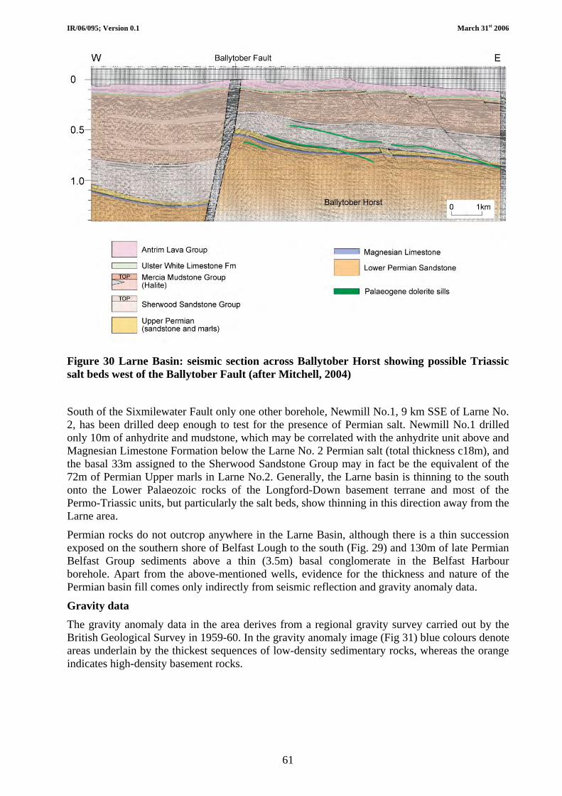
IR/06/095; Version 0.1 March 31st 2006
61
Figure 30 Larne Basin: seismic section across Ballytober Horst showing possible Triassic salt beds west of the Ballytober Fault (after Mitchell, 2004)
South of the Sixmilewater Fault only one other borehole, Newmill No.1, 9 km SSE of Larne No. 2, has been drilled deep enough to test for the presence of Permian salt. Newmill No.1 drilled only 10m of anhydrite and mudstone, which may be correlated with the anhydrite unit above and Magnesian Limestone Formation below the Larne No. 2 Permian salt (total thickness c18m), and the basal 33m assigned to the Sherwood Sandstone Group may in fact be the equivalent of the 72m of Permian Upper marls in Larne No.2. Generally, the Larne basin is thinning to the south onto the Lower Palaeozoic rocks of the Longford-Down basement terrane and most of the Permo-Triassic units, but particularly the salt beds, show thinning in this direction away from the Larne area.
Permian rocks do not outcrop anywhere in the Larne Basin, although there is a thin succession exposed on the southern shore of Belfast Lough to the south (Fig. 29) and 130m of late Permian Belfast Group sediments above a thin (3.5m) basal conglomerate in the Belfast Harbour borehole. Apart from the above-mentioned wells, evidence for the thickness and nature of the Permian basin fill comes only indirectly from seismic reflection and gravity anomaly data.
Gravity data
The gravity anomaly data in the area derives from a regional gravity survey carried out by the British Geological Survey in 1959-60. In the gravity anomaly image (Fig 31) blue colours denote areas underlain by the thickest sequences of low-density sedimentary rocks, whereas the orange indicates high-density basement rocks.

IR/06/095; Version 0.1 March 31st 2006
62
Figure 31 Bouguer gravity anomaly image with shaded relief, illumination from the NW.
Contour interval 2.5mGal. Modified from the GSNI Northern Ireland geophysical image atlas (Carruthers et al. 1997). Larne gravity minimum outlined in white.
The Permian salt is likely to be present in the deepest part of the basin, marked by the lowest gravity anomaly values. The image shows that there is a gravity anomaly minimum centred over Larne that extends c2.5km to the south and west of the town, and under the north of Larne Lough. The 2.5 mGal contour does not necessarily mark the limit of the Permian salt but it may indicate the shape of the Permian salt depocentre.
Seismic reflection data Only three conventional seismic reflection lines cross the area south of the Sixmilewater fault – lines DED 81/B, FG88-1 and FG88-07 (Fig. 32). A seismic survey shot by Shelf Exploration in

IR/06/095; Version 0.1 March 31st 2006
63
1997, using an airgun source in shallow water-filled pits, produced poor quality data. Line 81/B runs north-south along the coast road through Larne whereas lines FG88-7 and FG88-1 run eastwards to reach the coast at Larne and the shore of Larne Lough at Glynn, respectively. The quality of the data deteriorates where the lines cross the scarp onto the basalt and through the built-up areas of Larne town. Unfortunately, this means that the tie between the seismic reflection data and the synthetic seismogram generated from the downhole velocity survey at Larne No. 2 is not very clear.
Figure 32 Bedrock geology of Larne area (GSNI, 1994), showing seismic lines and possible extensions of known major faults (dashed red lines). Area enclosed by yellow indicates where the interpreted Top Magnesian Limestone reflector is at a two way time (TWT) equal to, or greater than, that measured in Larne No. 2.
The seismic reflection data are difficult to interpret but, at the intersections of FG88-7 and FG88-1 with NI81/B, the Triassic salt reflector package can clearly be seen dipping westwards and it is believed that the Permian salt may be present at least within the area outlined by yellow in Figure 32. This area is in the hanging wall of the extension of the Sixmilewater Fault, as mapped from the seismic data. It should be noted that the field mapping does not show this fault extending towards the coast at Larne, but this may be because of an almost total lack of rock outcrop within Larne town itself. However there is a topographic feature running ENE towards the coast, which may indicate the surface expression of the fault. The extension of the salt east of the Larne Lough Fault is a matter of conjecture, because there is no seismic control in this area.
The Permian salt can be recognised for a short distance on the three seismic lines where two reflectors are interpreted as the Top Salt and Top Magnesian Limestone by correlation with the Larne No. 2 synthetic seismogram (Fig. 33). This reflector package is impersistent.
FG88-7
FG88-1
NI81/B
Area east of Larne fault is notcovered by onshore seismicdata. Offshore seismic suggeststhat Permian and Triassic saltbeds continue offshore, and byinterpolation, on Islandmagee.
?

IR/06/095; Version 0.1 March 31st 2006
64
Figure 33 Correlation of seismic section NI-81/B with synthetic seismogram from Larne No.2, showing reflector packages associated with Permian and Triassic salt intervals (sources: Department of Commerce, 1981 and Penn, 1981).
Lough Neagh Basin
The lithostratigraphy of Permian and Triassic rocks in the Lough Neagh Basin (Figs 26 and 27) has been investigated by three deep boreholes in the area around the north end of Lough Neagh. In addition, because of the presence of coal-bearing Carboniferous strata on the west side of Lough Neagh in the Dungannon - Coalisland area (Figs 23 and 27), their distribution in the subsurface was explored by several shallower holes drilled on the western flank of the basin. A thin Permian sequence encountered in most of the latter holes never exceeded a thickness of 35m and as such represents the subsurface continuation of the sequence exposed near Cookstown as described previously.
At the north end of Lough Neagh three deep boreholes were drilled to investigate the hydrocarbon potential of the Lough Neagh Basin and of the thick Permo-Triassic sequence (Fig. 27). The Ballymacilroy Borehole reached a depth of 2272m and encountered an unbottomed sequence of almost 400m of Permian strata. Once again, the succession includes a section of the Magnesian Limestone (28m thick), underlain by about 250m of sandstone and conglomerate and overlain by 65m of the Gallagh Bridge Sandstone Formation (‘Permian Sandstone’) with 52m of the ‘Permian Upper Marls’ (52m) at the top. The two remaining boreholes were drilled south of Toome, about 1km apart, at Annaghmore and Ballynamullan near the shore of Lough Neagh, and 13km southwest of Ballymacilroy. Not surprisingly, their respective stratigraphies are very similar and record a thickness of almost 700m of Permian rocks in an unbottomed sequence (Naylor et al., 2003). Beneath the Magnesian Limestone is a maximum thickness of 542m of medium- to coarse-grained sandstone with pebbly sandstone and subordinate beds of red mudstone. The Magnesian Limestone (26m) is divided into a basal limestone unit 19m thick and an upper, anhydritic, unit about 7m thick. This upper, evaporitic, unit occurs at the same

IR/06/095; Version 0.1 March 31st 2006
65
stratigraphical position in the Lough Neagh Basin as the bed of halite developed immediately above the Magnesian Limestone at the base of the White Brae Mudstone Formation (‘Permian Upper Marls’) in the Larne Basin, 45km to the ENE. Above the Magnesian Limestone 50m of the Gallagh Bridge Sandstone Formation (equivalent to the ‘Permian Sandstone’) is overlain by 106m of the Drumderg House Formation (‘Permian Upper Marls’).
No halite beds have been drilled in the Permian section in the Lough Neagh Basin. If Permian halite beds are present within the Lough Neagh Basin then they are most likely to occur in the deepest part of the basin underneath the northeast, and possibly the southwest, part of Lough Neagh itself. In view of this possible distribution, the Lough Neagh Basin may be downgraded in terms of potential energy storage in underground Permian salt caverns, until or unless seismic reflection data is acquired across the lough itself.
Rathlin Basin
The Rathlin Basin is a sedimentary basin with a predominantly Permo-Triassic basin fill, underlain by a variable thickness of Carboniferous and/or Devonian rocks. In general form, the basin is a southeast-dipping half-graben lying between the Tow Valley Fault (TVF) to the southeast and the Foyle Fault to the northwest. A SW-NE trending ridge of relatively shallow Dalradian rocks separates the Rathlin Basin from the adjacent Foyle Basin, which dips northwest into the bounding Foyle Fault. The two basins are connected to the northeast in their offshore parts. The onshore part of the Rathlin Basin is largely concealed by lavas and tuffs of the Antrim Lava Group, but is marked by a pronounced Bouguer gravity anomaly low (Fig.34). Geophysical evidence presented in Mitchell (2004) shows that the basin is segmented by structures with a NW trend, with evidence for trends of approximate north-south and southwest-northeast orientations.
Figure 34 Bouguer gravity anomaly map of the Rathlin Basin showing the main depocentres in blue (source: BGS)
PM
M
M Magilligan PM Port More
IR/06/095; Version 0.1 March 31st 2006
66
The Port More borehole [3069 4435] showed the presence of at least 1897 m of Permo-Triassic rocks (Wilson and Manning, 1978), without reaching the Carboniferous. The Magilligan borehole [2683 4353], sited in the neighbouring Foyle Basin, encountered Carboniferous rocks at 990 m, proving a thickness of at least 357 m. The Permian appears to be absent in Magilligan but the lowest 66m of strata in Port More have been assigned to the Permian on the basis of c15m of mudstones with dolomitic cement and a thin rib of dolomitic limestone that may be correlated with the Permian Magnesian Limestone. The underlying sandstones contain rounded quartz grains, which are characteristic of the aeolian sandstones of the Lower Permian elsewhere in Northern Ireland.
This borehole does not reach the base of the Permian but halite, if present, would have been penetrated above the dolomitic mudstone beds. The Port More borehole did not penetrate the deepest part of the basin, which occurs to the southwest, as defined by the gravity anomaly data, so the Permian salt could be present here at depths of c2000 m. This is however considered unlikely in view of the thin Upper Permian section present in Port More.
Newtownards Trough
Putative Permian rocks are believed to exist in the Newtownards area, Co. Down, some 12km southeast of the Permian outcrop at Cultra. They are largely concealed in a NW-SE trending half-graben, the Newtownards Trough (Fig. 27), and are located mostly under the northern part of Strangford Lough. However, because of the absence of the Magnesian Limestone in all boreholes, the assignment of a Permian age is unsubstantiated and the true age of these rocks is not known. Borehole information reveals a sequence about 500m thick consisting entirely of clastic rocks. At the base, the ‘basal breccia’ (Coolbeg Breccia Formation) has a maximum thickness of 245m in a borehole near the centre of the trough while a borehole at the southwest margin showed only 1m of breccia. At the top of this succession is the 94m thick ‘Permian Upper Marls’ (Haw Hill Borehole Formation). Between the Coolbeg Breccia and Haw Hill Borehole formations, the Kennel Sandstone Formation and Newfort Breccia Formation consist exclusively of coarse-grained sandstone with breccia beds. No halite beds are known to occur in the Newtownards Trough.
On the south side of the Lagan Valley, southwest of Belfast, a sequence of putative Permian rocks, closely resembling the ‘Permian’ in the Newtownards Trough, rests unconformably on Ordovician rocks of the southern terrane. Although the Magnesian Limestone, or its equivalent the Belfast Harbour Evaporite Formation, is not recognised in the Lagan Valley, strata identical lithologically to the ‘Permian Upper Marls’ are present, underlain by up to 120m of sandstone and breccia.
No halite has been found or is expected to be present in the Permian of the Newtownards Trough.

IR/06/095; Version 0.1 March 31st 2006
67
7.2.2 Triassic In Northern Ireland, sedimentation is believed to have continued uninterrupted across the systemic boundary in deep Permo-Triassic sedimentary basins, although the position of that boundary is usually difficult to pinpoint. However, in the early Triassic, sedimentation spread beyond, and concealed, the margins of the Permian depositional basins, in the process creating an unconformable relationship with older Palaeozoic and Neoproterozoic rocks and reworking loose surface debris to form a basal conglomerate. The Triassic sequence in Northern Ireland is divided into three units, the Sherwood Sandstone Group, Mercia Mudstone Group and Penarth Group. Of these the Penarth Group is the youngest and thinnest of the Groups and is succeeded conformably by Jurassic strata. The Penarth Group and the Jurassic rocks are only very rarely exposed and will not be considered further. In contrast the outcrop of the Sherwood Sandstone Group is widespread and extends offshore, eastwards into the Irish Sea between Northern Ireland and Scotland and northwards into the Atlantic Ocean. Although the stratigraphy of the Mercia Mudstone Group was defined in the Rathlin Basin in north Co. Antrim by the Port More Borehole, the known occurrence of halite beds is restricted to the Larne Basin in southeast Co. Antrim (Fig. 27).
7.2.2.1 SHERWOOD SANDSTONE GROUP (FIGS 27 AND 35)
The Group consists of red-bed sediments mainly pink to reddish brown sandstone and silty sandstone, with brown mudstone accounting for up to one-third of the total thickness. The common occurrence of well-rounded (millet seed) sand grains suggests the influence of aeolian deposition. The Group is 648m thick at Larne, about 300m in the Lagan Valley and east Co. Tyrone, thins northwards to about 30m on the Dalradian Highland Border Ridge and reaches over 500m in the Port More Borehole, near Ballycastle.
7.2.2.2 MERCIA MUDSTONE GROUP (FIGS. 27 AND 35)
The outcrop of the Mercia Mudstone Group occurs predominantly at the periphery of the Antrim Plateau (Fig. 27). However, with the exception of coastal exposures in Co. Antrim extending from Cushendall in the north to Larne and then southwestwards to Belfast and the Lagan Valley, these relatively soft sedimentary rocks are very rarely exposed inland. The six constituent formations of the Mercia Mudstone Group were originally defined in the Port More Borehole, in north Co. Antrim, and overall consist of calcareous, reddish to brown mudstone and thin, laminated, micaceous siltstone that weather to a brick red colour. Sandstone is common only in the basal formation, the transitional unit from the underlying Sherwood Sandstone Group.
The maximum thickness of 1030m attained by the Group in Northern Ireland is based on the combined sections recorded in the Larne No. 1 and No. 2 boreholes. At Larne the Group includes 400m of halite beds that are 233m thick in the Newmill Borehole and only 40m thick at Carrickfergus in southeast Co. Antrim. The top of the Late Triassic Mercia Mudstone Group is transitional into the succeeding Early Jurassic Waterloo Mudstone Formation and accompanies the gradual change from continental conditions to an open marine environment.
7.2.2.2.1 Halite (salt) beds in the Mercia Mudstone Group of the Larne Basin
The distribution of known halite beds in the Mercia Mudstone Group in Northern Ireland is confined to the Larne Basin (Fig. 26) in southeast County Antrim and to the area between Carrickfergus and Larne. Discovered in the mid-19th century, the salt beds were exploited almost continuously by several mines using the pillar-and-stall method in the Carrickfergus and Eden areas. Although many of the mines had ceased production by the early 1900s a few maintained an output until 1958, when the last mine closed. Even during their productive period many of the
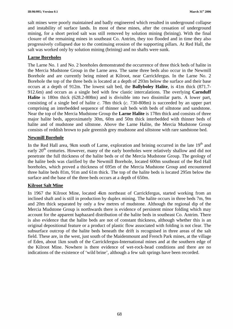
IR/06/095; Version 0.1 March 31st 2006
68
salt mines were poorly maintained and badly engineered which resulted in underground collapse and instability of surface lands. In most of these mines, after the cessation of underground mining, for a short period salt was still removed by solution mining (brining). With the final closure of the remaining mines in southeast Co. Antrim, they too flooded and in time they also progressively collapsed due to the continuing erosion of the supporting pillars. At Red Hall, the salt was worked only by solution mining (brining) and no shafts were sunk.
Larne Boreholes The Larne No. 1 and No. 2 boreholes demonstrated the occurrence of three thick beds of halite in the Mercia Mudstone Group in the Larne area. The same three beds also occur in the Newmill Borehole and are currently being mined at Kilroot, near Carrickfergus. In the Larne No. 2 Borehole the top of the three beds is located at a depth of 293m below the surface and their base occurs at a depth of 912m. The lowest salt bed, the Ballyboley Halite, is 41m thick (871.7-912.6m) and occurs as a single bed with few clastic intercalations. The overlying Carnduff Halite is 180m thick (628.2-808m) and is divisible into two dissimilar parts. A lower part, consisting of a single bed of halite c. 78m thick (c. 730-808m) is succeeded by an upper part comprising an interbedded sequence of thinner salt beds with beds of siltstone and sandstone. Near the top of the Mercia Mudstone Group the Larne Halite is 178m thick and consists of three major halite beds, approximately 30m, 60m and 50m thick interbedded with thinner beds of halite and of mudstone and siltstone. Above the Larne Halite, the Mercia Mudstone Group consists of reddish brown to pale greenish grey mudstone and siltstone with rare sandstone bed.
Newmill Borehole In the Red Hall area, 9km south of Larne, exploration and brining occurred in the late 19th and early 20th centuries. However, many of the early boreholes were relatively shallow and did not penetrate the full thickness of the halite beds or of the Mercia Mudstone Group. The geology of the halite beds was clarified by the Newmill Borehole, located 600m southeast of the Red Hall boreholes, which proved a thickness of 695m of the Mercia Mudstone Group and encountered three halite beds 81m, 91m and 61m thick. The top of the halite beds is located 295m below the surface and the base of the three beds occurs at a depth of 650m.
Kilroot Salt Mine In 1967 the Kilroot Mine, located 4km northeast of Carrickfergus, started working from an inclined shaft and is still in production by duplex mining. The halite occurs in three beds 7m, 9m and 20m thick separated by only a few metres of mudstone. Although the regional dip of the Mercia Mudstone Group is northwards there is evidence of persistent minor folding which may account for the apparent haphazard distribution of the halite beds in southeast Co. Antrim. There is also evidence that the halite beds are not of constant thickness, although whether this is an original depositional feature or a product of plastic flow associated with folding is not clear. The subsurface outcrop of the halite beds beneath the drift is recognised in three areas of the salt field. These are, in the west, just south of the Maidenmount and French Park mines, at the village of Eden, about 1km south of the Carrickfergus-International mines and at the southern edge of the Kilroot Mine. Nowhere is there evidence of wet-rock-head conditions and there are no indications of the existence of ‘wild brine’, although a few salt springs have been recorded.

IR/06/095; Version 0.1 March 31st 2006
69
Figure 35 Summary successions and correlation of selected Triassic sequences in Northern Ireland. (after Mitchell, 2004)

IR/06/095; Version 0.1 March 31st 2006
70
Salt thickness The Glenstaghey Formation contains the Larne Halite Member, and the underlying Craiganee Formation contains the Carnduff Halite and Ballyboley Halite members. Of these three only the Larne Halite, in both Larne boreholes, and the Carnduff halite, in Larne No. 2 only, are thick enough to have potential to house gas storage caverns (Table 7).
Table 7 Triassic salt beds in Larne and Newmill boreholes
Larne No. 1 Larne No. 2 Newmill No. 1 Rock Unit Depth range (m
MSL) Thickness (m) Depth range (m MSL) Thickness (m) Depth range
(m MSL) Thickness
(m) Larne 358.4-839.6 481 (331 net) 282.5-460.9 178 (164 net) 96-120.7 24
Carnduff 893.3-934.5 41 (15 net) 618.1-800 182 281.3-357.8 424.3-510.5
77 86
Ballyboley 996.2-1022.5 26 861.7-902.5 41 557.8-632.5 75
Purity The purity of the three Triassic salt units can be summarised from the descriptions of the cuttings samples in the mudlogs and the geophysical log responses in the three deep boreholes.
The Larne halite
Larne No.1 Massive beds of halite, up to 38 m thick, occur with scattered pockets of red and green mudstone. Interbedded with mudstone laminae. Two thin siltstone beds. Seven igneous intrusions of olivine dolerite, totalling 40 metres in apparent thickness, contacts dipping at 40o – 80o to the horizontal. Two dyke intersections of 18 and 14.6 m apparent thickness.
Larne No. 2 Three major halite beds up to 33m thick interbedded with thinner (2 – 5m) beds of halite and mudstone/siltstone.
Pure halite: gamma low; sonic 67 – 70 msec/ft. Where interbedded with mudstone, or impure halite log responses show more variation.
Newmill No. 1 Massive halite beds up to 25m thick, interbedded with red brown silty mudstones. Mudstone inclusions may occur in the massive salt beds.
Carnduff halite
Larne No.1 Mudstone dominant in upper part. More massive salt beds interbedded with red and green mudstones in lower part.
Larne No. 2 Five salt beds >5m thick, thickest is 70m thick and relatively pure.
Newmill No. 1 Two major salt-bearing intervals. Upper interval shows relatively pure salt beds and mudstone increasing downwards. Top 56m thick is massive salt with 4 interbeds of mudstone 1 – 2m thick, middle 14m has 4 alternations of salt and mudstone and lowest 6m is mudstone with minor salt. Lower interval, by contrast, has up to 50% mudstone in upper part, with a massive salt bed 15m thick towards the base.
Ballyboley halite
Larne No.1 Twelve salt beds, mainly thin, totalling 13m. Interbedded with green mudstone with grey siltstone laminae. Anhydrite nodules common.
Larne No. 2 Four major salt beds of <7m thick. Interbedded with mudstone, especially in lower part.
Newmill No. 1 Four salt beds >5m thick, thickest is 23m thick with bottom 7m relatively pure.

IR/06/095; Version 0.1 March 31st 2006
71
Analyses Samples taken from cores in the salt beds of the Larne Halite Member in Larne No. 1 were analysed for purity (Table 8). The minimum and maximum values for sodium chloride (calculated from chloride concentration) and insoluble matter (presumably mudstone) from these analyses are given below. Bulk samples from three of the thickest salt beds give 85 – 88 %NaCl. The values for insoluble matter indicate the amount of mudstone that may be dispersed through the salt.
Table 8 Analyses of salt samples from Larne Halite Member in Larne No. 1 cores
Min % Max % NaCl 75.75 89.88 Insolubles 5.32 18.61
The bulk NaCl content for the Larne halite can also be calculated from the density logs in a similar manner to the calculations for the Permian salt given above. The Mercia Mudstone Group mudstone matrix has a log density of 2.68g/cc, giving a mean %NaCl of 86.2% for the relatively pure bed in Larne No. 2 – which compares well with the results of the analyses made on the purest Larne halite beds in Larne No. 1.
There is little published data on the salt from the Carrickfergus area, with analyses from the salt of the Duncrue mine given in Table 9.
Table 9 Analyses of salt samples from Duncrue mine
J Chemico-Agricultural Soc., Ulster 1880, 14, 80
Miscampbell (1894, p. 566)
NaCl 91.83 NaCl 96.17 CaSO4 4.80 KCl 0.15 MgCl2 0.68 MgCl2 0.03 Clay 0.37 Al2O3 0.35 SiO2 0.82 H2O 2.32 H2O 2.48
The salt worked in the Carrickfergus area is c260 m below the top of the Mercia Mudstone Group and is almost certainly the Larne Halite. The thickest salt bed is <30m thick and the salt beds are variable in quality and thickness in this area. The full sequence of the Mercia Mudstone group is not penetrated in this area, most of the shafts and boreholes bottoming within the salt.
7.2.2.3 DISTRIBUTION OF TRIASSIC SALT BEDS IN THE LARNE BASIN
The general distribution and thickness trends for the Triassic salt strata in the area south of the Sixmilewater Fault is given above. The variation in the thickness of the salt beds between the Larne No. 1 and Larne No. 2 boreholes must be taken into consideration in the assessment of the suitability of the Triassic salt for the development of salt caverns. Salt beds have not been proved north of the Sixmilewater Fault where the Mercia Mudstone section drilled by the Ballytober well does not contain salt. However, seismic reflection data from the 1988 Fynegold seismic survey provides indications that Triassic salt may occur to the west and east of the north-south trending Ballytober horst on which Ballytober 1 was drilled (Fig. 30). To the east, near the coast between Larne and Ballygalley Bay Lines FG88-02 and FG88-05 show some reflectors with
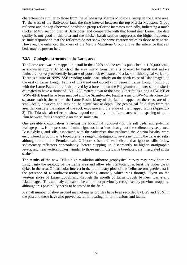
IR/06/095; Version 0.1 March 31st 2006
72
characteristics similar to those from the salt-bearing Mercia Mudstone Group in the Larne area. To the west of the Ballytober fault the time interval between the top Mercia Mudstone Group reflector and the top Sherwood Sandstone group reflector increases markedly, indicating a much thicker MMG section than at Ballytober, and comparable with that found near Larne. The data quality is not good in this area and the thicker basalt section suppresses the higher frequency seismic response so that the reflectors do not show the same characteristics as those near Larne. However, the enhanced thickness of the Mercia Mudstone Group allows the inference that salt beds may be present here.
7.2.3 Geological structure in the Larne area The Larne area was re-mapped in detail in the 1970s and the results published at 1:50,000 scale, as shown in Figure 32. Much of the area inland from Larne is covered by basalt and surface faults are not easy to identify because of poor rock exposure and a lack of lithological variation. There is a suite of NNW-SSE trending faults, particularly on the north coast of Islandmagee, to the east of Larne Lough. Faults of this trend undoubtedly run beneath Larne Lough, joining up with the Larne Fault and a fault proved by a borehole on the Ballylumford power station site is estimated to have a throw of 150 – 200 metres down to the east. Other faults along a SW-NE or WSW-ENE trend have been mapped and the Sixmilewater Fault is a major SW-NE structure that separates sub-basins within the Larne Basin. Many of the faults mapped on the coast are of a small-scale, however, and may not be significant at depth. The geological field slips from the area demonstrate the nature of the rock exposure and the scale of the mapped faults (Appendix 2). The Triassic salt reflectors show a good continuity in the Larne area with a spacing of up to 2km between faults detectable on the seismic data.
One possible complication regarding the horizontal continuity of the salt beds, and potential leakage paths, is the presence of minor igneous intrusions throughout the sedimentary sequence. Basalt dykes, and sills, associated with the volcanism that produced the Antrim basalts, were encountered in both Larne boreholes at a range of stratigraphic levels including the Triassic salts, although not in the Permian salt. Offshore seismic lines indicate that igneous sills follow sedimentary reflectors concordantly, before stepping up discordantly to higher stratigraphic levels, and near vertical dykes, similar to those met in the Larne boreholes, are interpreted at the seabed.
The results of the new Tellus high-resolution airborne geophysical survey may provide more insight into the geology of the Larne area and allow identification of at least the wider basalt dykes in the area. Of particular interest in the preliminary plots of the Tellus aeromagnetic data is the presence of a southwest-northeast trending anomaly which runs through Glynn on the western shore of Larne Lough and through the mouth of Larne Lough between Larne and Islandmagee. This anomaly appears to be a fault not previously recognised by previous mapping, although this possibility needs to be tested in the field.
A small number of short ground magnetometer profiles have been recorded by BGS and GSNI in the past and these have also proved useful in locating minor intrusions and faults.
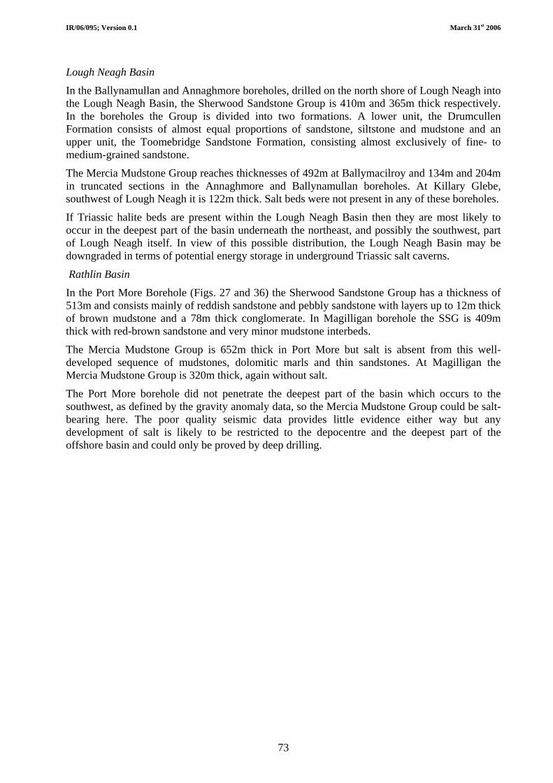
IR/06/095; Version 0.1 March 31st 2006
73
Lough Neagh Basin
In the Ballynamullan and Annaghmore boreholes, drilled on the north shore of Lough Neagh into the Lough Neagh Basin, the Sherwood Sandstone Group is 410m and 365m thick respectively. In the boreholes the Group is divided into two formations. A lower unit, the Drumcullen Formation consists of almost equal proportions of sandstone, siltstone and mudstone and an upper unit, the Toomebridge Sandstone Formation, consisting almost exclusively of fine- to medium-grained sandstone.
The Mercia Mudstone Group reaches thicknesses of 492m at Ballymacilroy and 134m and 204m in truncated sections in the Annaghmore and Ballynamullan boreholes. At Killary Glebe, southwest of Lough Neagh it is 122m thick. Salt beds were not present in any of these boreholes.
If Triassic halite beds are present within the Lough Neagh Basin then they are most likely to occur in the deepest part of the basin underneath the northeast, and possibly the southwest, part of Lough Neagh itself. In view of this possible distribution, the Lough Neagh Basin may be downgraded in terms of potential energy storage in underground Triassic salt caverns.
Rathlin Basin
In the Port More Borehole (Figs. 27 and 36) the Sherwood Sandstone Group has a thickness of 513m and consists mainly of reddish sandstone and pebbly sandstone with layers up to 12m thick of brown mudstone and a 78m thick conglomerate. In Magilligan borehole the SSG is 409m thick with red-brown sandstone and very minor mudstone interbeds.
The Mercia Mudstone Group is 652m thick in Port More but salt is absent from this well-developed sequence of mudstones, dolomitic marls and thin sandstones. At Magilligan the Mercia Mudstone Group is 320m thick, again without salt.
The Port More borehole did not penetrate the deepest part of the basin which occurs to the southwest, as defined by the gravity anomaly data, so the Mercia Mudstone Group could be salt-bearing here. The poor quality seismic data provides little evidence either way but any development of salt is likely to be restricted to the depocentre and the deepest part of the offshore basin and could only be proved by deep drilling.

IR/06/095; Version 0.1 March 31st 2006
74
Figure 36 Comparison of the Triassic rocks in the Port More and Larne No. 2 boreholes

IR/06/095; Version 0.1 March 31st 2006
75
7.2.4 Potential of salt beds in Larne Basin for energy storage in caverns The salt beds in the Larne area have potential to host salt caverns for underground energy storage, and the most important factors determining this are as follows:
Permian Salt
• The Permian salt, as drilled in Larne No. 2, is over 100 m thick, c 1700m deep and pure.
• It is probably restricted geographically to an area south of the Sixmilewater Fault, within 5-6km of the Larne No. 2 borehole. A seismic reflector package associated with the salt can be seen intermittently on the seismic data in this area
• Within this area it may be affected by faulting and/or minor dolerite dyke intrusions.
• It may be subject to rapid lateral thickness variations because of halokinesis (tectonically-induced salt movement) in the geological past.
Triassic Salt
• There are three salt units - the Larne, Carnduff and Ballyboley halites but only the Larne (in Larne No. 1 and 2) and Carnduff (in Larne No. 2) halite units are thick enough at these locations to have potential for underground storage in salt caverns.
• The Larne and Carnduff halite units occur between depths of 280 and 935m below sea level.
• The Triassic salt is thickest in Larne adjacent to the Sixmilewater Fault and thins south to the Carrickfergus area. It may also occur north of the Sixmilewater Fault, off the Ballytober Fault, but this has yet to be proved by drilling.
• The units contain several thick pure halite beds but also contain significant mudstone interbeds
• The Larne halite, in Larne No. 2, is cut by at least 7 thin dolerite intrusions.
• The salt beds have thick mudstone caprocks within the Mercia Mudstone Group
• Triassic salt beds show significant thickness variations between the Larne No. 1 and No. 2 boreholes, which are only 600 metres apart. The Carnduff halite, for example, increases from 41m in Larne No. 1 to 182m in Larne No. 2. It is possible that some of the section in Larne No.1 is cut out by faulting (slickensides are recorded near the top of the Carnduff halite). However, the Larne halite shows an opposite thickness trend, decreasing from 331m (net) in Larne No.1 to 164m in Larne No.2, so it is probable that stratigraphic variation is important on a local as well as regional scale. Halokinesis may be important close to the more major faults.
The limited information about the Triassic and especially the Lower Permian salt in the Larne area may be summarized below:

IR/06/095; Version 0.1 March 31st 2006
76
Table 10 Properties of Permian and Triassic salt beds in the Larne area
Triassic salt Permian salt
Larne Halite Carnduff Halite Ballyboley Halite
Thickness 113m (one bed) 481 m (gross max.) 182 m (gross max.) 75 m (gross max.)
Variation Unknown General trend of thinning towards south from Larne boreholes to Carrickfergus saltfield
Significant lateral thickness variation over a short distance (e.g. Larne No. 1 to Larne No. 2)
Caprock 72 m of mudstones and siltstones Mudstones and minor siltstones of Mercia Mudstone Group form caprock
Depth (max) 1678 – 1791 m 358 –840 m Larne No. 1 893 – 935 m Larne No. 1 996 – 1022 m Larne No. 1
Variation Unknown General trend of shallowing towards south from Larne boreholes to Carrickfergus saltfield
Significant local depth variation over a short distance, especially across faults
Purity c 92% NaCl (mean log) c 90% NaCl (max ) c 85 – 90 % (logs) c 85 – 90 % (logs)
Variation Uniform log response Analyses of Larne Halite from Larne cores give a range 76 – 90% NaCl.
Impurities occur dispersed through salt as insolubles (10 - 24 %) in Larne cores, and as interbeds of siltstone and mudstone.
Distribution Only proved in Larne No.2 well; absent from Newmill.
Probably confined to area around Larne, south of the Sixmilewater Fault, and <6km from Larne
Proven south of Sixmilewater Fault from Larne to Carrickfergus; probably more widespread in this area, but thickest beds probably within 6km of Sixmilewater Fault.
May occur north of Sixmilewater Fault near coast and to west of Ballytober Fault, from interpretation of seismic and gravity anomaly data
Intrusions None recorded Larne Halite in Larne No. 2 cut by 7 thin dolerite intrusions. Apparent total thickness of 40m reduces to actual total width of 7 – 30m depending on angle of dip. Most dykes in field are 1 – 3 m wide. Only two dykes have been recorded in the Kilroot salt mine.

IR/06/095; Version 0.1 March 31st 2006
77
7.3 SUITABILITY (ONSHORE) OF NORTHERN IRELAND ROCK UNITS FOR UNDERGROUND ENERGY STORAGE
Section 4 of this report outlined the geological environments that have been, or could be, used for underground energy storage as follows:
1. Depleting oil/gas reservoirs
2. Aquifers
3. Salt caverns
4. Lined rock caverns
5. Abandoned mines
This section evaluates the suitability of the rock units found in Northern Ireland (described above), to host these different types of underground energy storage facilities. The distribution of the rocks relative to the energy infrastructure is discussed.
7.3.1 Proterozoic (Dalradian Supergroup) Location: Northwest quadrant in Sperrin Mountains and northeast Co. Antrim
Figure 37 Distribution of Dalradian rocks in Northern Ireland (after Mitchell, 2004)

IR/06/095; Version 0.1 March 31st 2006
78
The Dalradian Supergroup is formed of metamorphic rocks which theoretically could have some potential to host lined rock caverns. The rocks are typically of a mixture of quartzites and psammites with a significant proportion of much softer micaceous lithologies. It is likely that the quartzites and psammite lithologies would provide a high level of rock strength but this could be compromised by the proportion of interbedded softer lithologies in any particular section of rock. Minor units of meta-igneous rocks and meta-limestones are unlikely to be thick enough to be of use in a storage context. Metamorphic rocks are regarded as being poor aquifers and although transmission of groundwater along joints is known, they tend to have low water-bearing capacity.
The Dalradian rocks are distributed in the west of Northern Ireland, forming the high ground of the Sperrins, and many of the increasing number of wind farms are situated on them.
Depleting oil/gas reservoirs No potential
Aquifers No potential
Salt caverns No potential
Lined rock caverns Some rock types may be suitable, requires further study
Abandoned mines No potential

IR/06/095; Version 0.1 March 31st 2006
79
7.3.2 Ordovician (Tyrone Igneous Complex) Location: Northwest quadrant in County Tyrone
Figure 38 Tyrone Igneous Complex (after Mitchell, 2004)
Very large area of extremely variable igneous lithologies which are in places very poorly exposed. These rocks have only limited to non-existent aquifer potential. The igneous rocks may contain rock types suitable for hard rock caverns but the distribution, thickness and quality is very poorly understood. This is also an area with high mineral prospectivity which could be adversely affected by underground energy storage.
Depleting oil/gas reservoirs No potential
Aquifers No potential
Salt caverns No potential
Lined rock caverns Some rock types may be suitable, requires further study
Abandoned mines No potential

IR/06/095; Version 0.1 March 31st 2006
80
7.3.3 Ordovician-Silurian (Leadhills Supergroup, Gala and Hawick groups) Location: Southeast quadrant in Counties Armagh and Down
Figure 39 Lower Palaeozoic rocks of counties Down and Armagh (after Mitchell, 2004) These Lower Palaeozoic rocks form very thick sections of rock often dominated either by greywacke sandstones or by thick sections of mudstone (slate). Sections dominated by greywacke sandstones should provide a consistently high degree of rock strength and competence. These rocks are used widely as aggregates for road construction. Mudstone (slate) occurs regularly as thin interbeds but these are unlikely to represent a major problem. These rocks have universally low to negligible aquifer potential from fractures only.
The widespread distribution of these rocks in southeast Northern Ireland is a positive factor for their potential for lined rock cavern facilities, although they are distant from most of the currently installed wind farms.
Depleting oil/gas reservoirs No potential
Aquifers No potential
Salt caverns No potential
Lined rock caverns Some rock types may be suitable, requires further study
Abandoned mines No potential

IR/06/095; Version 0.1 March 31st 2006
81
7.3.4 Devonian (Newry Igneous Complex) Location: Southeast quadrant in south Counties Armagh and Down
Figure 40 Newry Igneous Complex (after Mitchell, 2004) This is a granitic body measuring 35km by 10 km extending southwest – northeast from Newry to Dromara in County Down. It probably extends to at least 10 kilometres depth and the surface weathering of the granodiorite is unlikely to affect the rock at depth. Typically granodiorite is not known for its aquifer properties and at depth it is unlikely that joint planes visible at the surface will be preserved. It therefore has potential for lined rock cavern facilities and the south-north gas pipeline runs through the southwestern granodiorite pluton in South Armagh. Depleting oil/gas reservoirs No potential
Aquifers No potential
Salt caverns No potential
Lined rock caverns Some rock types may be suitable, requires further study
Abandoned mines No potential
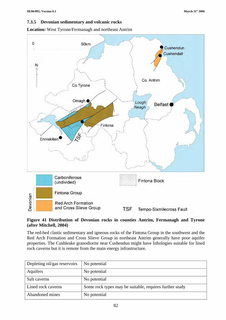
IR/06/095; Version 0.1 March 31st 2006
82
7.3.5 Devonian sedimentary and volcanic rocks Location: West Tyrone/Fermanagh and northeast Antrim
Figure 41 Distribution of Devonian rocks in counties Antrim, Fermanagh and Tyrone (after Mitchell, 2004)
The red-bed clastic sedimentary and igneous rocks of the Fintona Group in the southwest and the Red Arch Formation and Cross Slieve Group in northeast Antrim generally have poor aquifer properties. The Cushleake granodiorite near Cushendun might have lithologies suitable for lined rock caverns but it is remote from the main energy infrastructure.
Depleting oil/gas reservoirs No potential
Aquifers No potential
Salt caverns No potential
Lined rock caverns Some rock types may be suitable, requires further study
Abandoned mines No potential
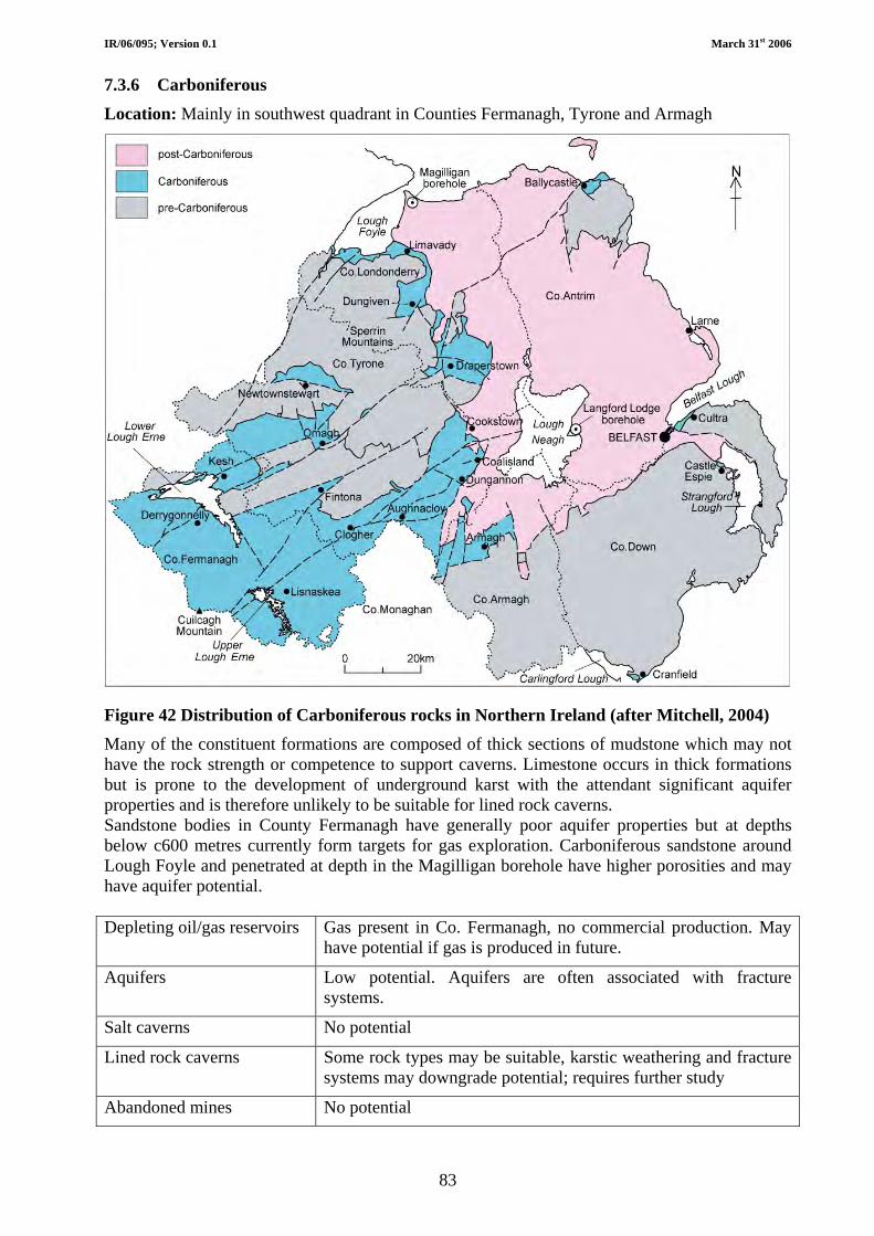
IR/06/095; Version 0.1 March 31st 2006
83
7.3.6 Carboniferous Location: Mainly in southwest quadrant in Counties Fermanagh, Tyrone and Armagh
Figure 42 Distribution of Carboniferous rocks in Northern Ireland (after Mitchell, 2004) Many of the constituent formations are composed of thick sections of mudstone which may not have the rock strength or competence to support caverns. Limestone occurs in thick formations but is prone to the development of underground karst with the attendant significant aquifer properties and is therefore unlikely to be suitable for lined rock caverns. Sandstone bodies in County Fermanagh have generally poor aquifer properties but at depths below c600 metres currently form targets for gas exploration. Carboniferous sandstone around Lough Foyle and penetrated at depth in the Magilligan borehole have higher porosities and may have aquifer potential. Depleting oil/gas reservoirs Gas present in Co. Fermanagh, no commercial production. May
have potential if gas is produced in future.
Aquifers Low potential. Aquifers are often associated with fracture systems.
Salt caverns No potential
Lined rock caverns Some rock types may be suitable, karstic weathering and fracture systems may downgrade potential; requires further study
Abandoned mines No potential

IR/06/095; Version 0.1 March 31st 2006
84
7.3.7 Permian Location: Northeast quadrant beneath Antrim Plateau (Fig. 27).
Thick sequences of Permian sandstones occur at depth beneath the Antrim plateau and, in parts, have porosity and permeability characteristics that indicate good to excellent hydrocarbon reservoir potential. This equates to the rocks also having good aquifer potential (Fig. 43). Unfortunately, because of the thick cover of basalts above the Permian rocks it is difficult to see the geological structure in any detail. The location of competent structural traps in the concealed Permian rocks of Northern Ireland is unknown and thus their potential to act in a storage capacity for underground energy in untested. Exploration for oil and gas may reveal some further information about the structure of the Permian strata at depth, particularly if new seismic or well data is acquired. There are two current licences in the Rathlin Basin and one in the Larne Basin. The Permian sandstone aquifers also have potential as geothermal energy resources at depths up to 3000 metres, although this remains to be tested. Permian halite (Salt) beds are known to occur at depth in the Larne area of southeast Co. Antrim. The halite occurs in a single bed 113m thick and is believed to contain few impurities. At present there is little additional information on its subsurface distribution. It may be affected by minor Palaeogene igneous intrusions and/or faulting. All salt beds may be affected to a degree by halokinesis. Depleting oil/gas reservoirs Permian Enler Group sandstones are reservoir targets for oil and
gas exploration beneath the Antrim Plateau. May have potential if oil or gas field discoveries are made and developed in future.
Aquifers Low-medium potential. Good quality aquifers in part but distribution and structure poorly understood due to lack of data.
Salt caverns Medium to high potential. Thick salt beds but lack of data about possibly restricted distribution
Lined rock caverns Low potential.
Abandoned mines No potential.
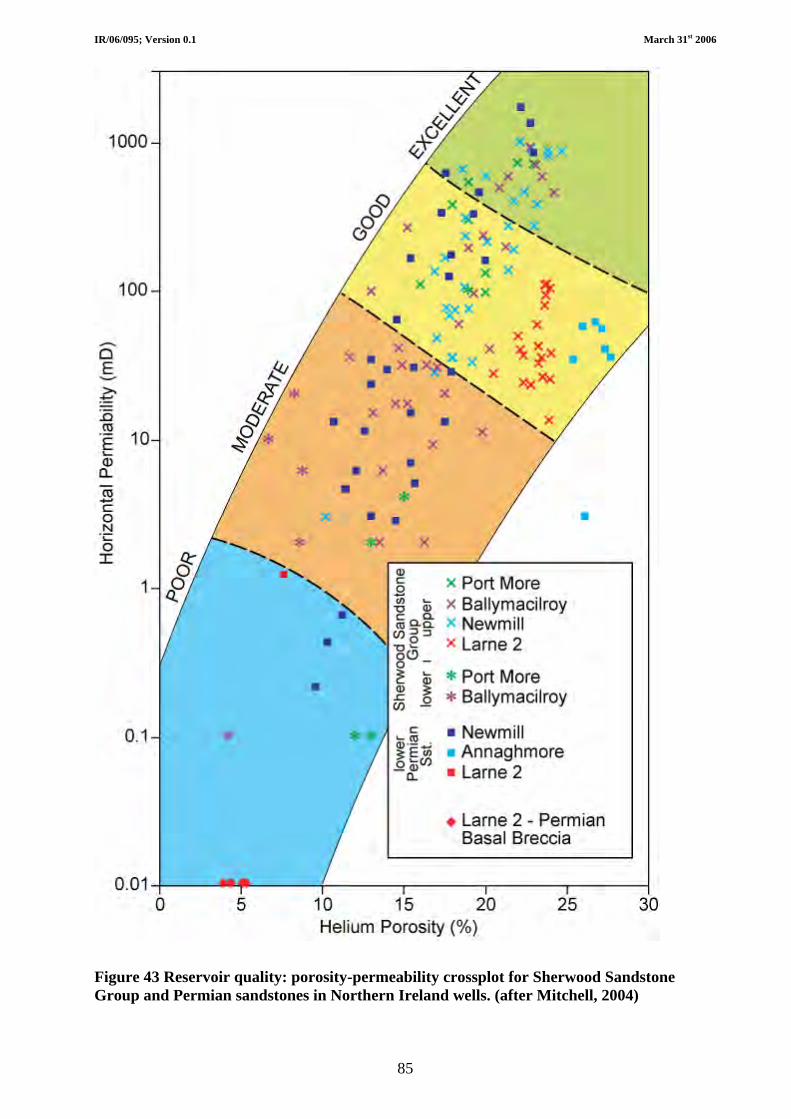
IR/06/095; Version 0.1 March 31st 2006
85
Figure 43 Reservoir quality: porosity-permeability crossplot for Sherwood Sandstone Group and Permian sandstones in Northern Ireland wells. (after Mitchell, 2004)

IR/06/095; Version 0.1 March 31st 2006
86
7.3.8 Triassic Location: Northeast quadrant beneath Antrim Plateau (Fig. 27)
Sequences of Triassic sandstones up to 650m thick occur at depth beneath the Antrim plateau and, in parts, have porosity and permeability characteristics that indicate good to excellent hydrocarbon reservoir potential. This equates to the rocks also having good aquifer potential (Fig. 33). At shallow depths in many parts of Northern Ireland the sandstones of the Sherwood Sandstone Group are an important aquifer supplying groundwater for public consumption. Unfortunately, because of the thick cover of basalts above the Triassic rocks it is difficult to see the geological structure at depth in any detail. The location of competent structural traps in the concealed Triassic rocks of Northern Ireland is unknown and thus their potential to act in a storage capacity for underground energy in untested.
The Sherwood Sandstone Group also forms the main reservoir target for oil and gas exploration in the concealed basins beneath the Antrim Plateau. Current and future exploration programmes may improve our knowledge of the structure and properties of these rocks at depth. The Sherwood Sandstone Group aquifers also have potential as intermediate and deep geothermal energy resources at depths up to c2000 metres, although this remains to be tested. Triassic halite (salt) beds are known to occur in southeast Co. Antrim between Larne and Carrickfergus. At Kilroot the salt beds outcrop near the shore of Belfast Lough but dip northwards beneath the edge of the Antrim plateau. Salt mining has been practised there for over 150 years. The salt beds at Kilroot are relatively thin but a borehole at Newmill demonstrates that they thicken and deepen northwards and at Larne are more than 470m thick. At Larne, in all of the three salt beds, the halite is interbedded to varying degrees with thin layers of siltstone and mudstone. The salt beds may be affected by minor Palaeogene igneous intrusions as found in the Larne boreholes and/or faulting. All salt beds may be affected to a degree by halokinesis. Depleting oil/gas reservoirs Triassic Sherwood Sandstone Group sandstones are primary
reservoir targets for oil and gas exploration beneath the Antrim Plateau. May have potential if oil or gas field discoveries are made and developed in future.
Aquifers Low to medium potential. Good quality aquifers widely distributed but structure poorly understood due to sparse borehole data and poor quality seismic data.
Salt caverns Medium to high potential. Thick salt beds in Larne basin but negative factors may include presence of siltstone/mudstone interbeds, minor dyke intrusions and faulting.
Lined rock caverns Low potential.
Abandoned mines Low potential. Abandoned mines in Carrickfergus area are variably brine-filled, unstable and prone to collapse.

IR/06/095; Version 0.1 March 31st 2006
87
7.3.9 Jurassic-Cretaceous Location: Northeast quadrant beneath Antrim Plateau (Fig. 44).
Jurassic mudstones (Waterloo Mudstone Formation) represent a thin section of soft rock that is the main cause of instability around the edge of the Antrim Plateau. These rocks have no storage potential. The white Cretaceous chalk (Ulster White Limestone Formation) is exposed at the margins of the Antrim Plateau and is encountered in deep boreholes drilled through the basalt lavas. Although the chalk has a total thickness of 133m this is never recorded at any one locality and 30-60m is a more usual estimate. The chalk is an important local aquifer and is prone to the development of karstic features. Its thinness, fracturing, karstic development and shallow depth mean that it has little or no storage potential. Depleting oil/gas reservoirs No potential
Aquifers Low potential. Chalk aquifers are associated with fracture porosity and are shallow.
Salt caverns No potential
Lined rock caverns Low potential, karstic weathering and fracture systems may downgrade potential.
Abandoned mines No potential

IR/06/095; Version 0.1 March 31st 2006
88
Figure 44 Distribution of Cretaceous rocks in Northern Ireland (after Mitchell, 2004)
IR/06/095; Version 0.1 March 31st 2006
89
7.3.10 Palaeogene (Antrim Lava Group) Location: Northeast quadrant forming the surface rocks of the Antrim Plateau (Fig. 45) Basalt lavas of the Antrim Lava Group underlie the Antrim Plateau and are exposed in cliffs on all its sides. A maximum thickness of 780m is recorded in the Ballymacilroy Borehole. The basalt lavas typically occur in flows rarely more than 10m thick which are characterised by highly weathered tops and bases and a massive centre to each flow, with numerous zeolite-filled vesicles throughout. Basalt lavas are typically poor aquifers, although locally fractures enhance the yield of wells and boreholes. It is unlikely that the weathered portions of the flows would provide sufficient rock strength and competence in excavations to be used for lined rock caverns. Depleting oil/gas reservoirs No potential
Aquifers Low potential – fracture porosity produces unsuitable aquifer type.
Salt caverns No potential
Lined rock caverns Low potential; weathered lava flow tops reduce rock strength in thin flows.
Abandoned mines No potential – Interbasaltic mines are thin and liable to water ingress.

IR/06/095; Version 0.1 March 31st 2006
90
Figure 45 Distribution of Antrim Lava Group and Lough Neagh Clay Group rocks (after Mitchell, 2004)

IR/06/095; Version 0.1 March 31st 2006
91
7.3.11 Mourne Mountains and Slieve Gullion Igneous Complexes Location: Southeast quadrant in southeast Co. Down (see Fig. 40)
At surface the Mourne Mountains Igneous Complex consists of five principal granite intrusions at two separate centres. The granite plutons probably extend to several kilometres deep. Surface weathering and jointing of the granite is a normal feature but it is unlikely to affect the granite at depth so it is a suitable lithology for lined rock caverns. Typically granite is not known for its aquifer properties and at depth it is unlikely that joint planes visible at the surface will be preserved. There is likely to be a certain amount of information about the various rock types and their properties from past site investigations carried out in connection with the design and construction of the Spelga and Silent Valley reservoirs, including the Silent Valley tunnel. The Mourne Mountains are classified as an Area of Outstanding Natural Beauty and it is distant from most of the energy infrastructure.
The Slieve Gullion igneous centre consists of a Central Complex of gabbro and granophyre encircled by a ring dyke of porphyritic felsite and granophyre (Gamble et al. 1976). Camlough, on the northeastern flank of Slieve Gullion, was chosen as the site for a Hydroelectric Pump Storage Scheme in the late 1960s. Exploratory drilling took place at the site of the proposed upper reservoir, and at the ends of the proposed tunnels in 1970-71. An access tunnel 868 metres long, and 4.9m by 6.3 m in cross-section, was driven into the mountain in 1971-72 before the project was halted in 1972. Additional drill holes probed the walls and roof of the access tunnel in the ‘cavern’ area of the proposed underground hydroelectric power station. There is a considerable amount of information about the rock types and their strengths and permeabilities from these investigations. The results of the drilling were generally favourable in terms of the rock types and their properties. It is possible that the original scheme should be re-evaluated, as well as the potential of the rocks for lined rock caverns. The site lies close to both the north-south pipeline and the 275KV electricity interconnector.
Two boreholes drilled into the granites of the Mourne Mountains recorded elevated temperatures and it is possible that both the Mourne Mountain and Slieve Gullion igneous complexes may have potential as ‘hot dry rock’ sources of geothermal energy.
Depleting oil/gas reservoirs No potential
Aquifers No potential
Salt caverns No potential
Lined rock caverns Medium potential – data from the 1970s Camlough Hydroelectric Pump Storage Scheme investigations could form the basis of further study.
Abandoned mines No potential

IR/06/095; Version 0.1 March 31st 2006
92
7.3.12 Lough Neagh Group Location: Within the area of the Antrim Plateau at Ballymoney and around and underneath Lough Neagh (Fig. 45). The Lough Neagh Group comprises at least 400m of relatively soft, and in parts water-bearing clays, thin sands and thick beds of lignite. Experience of mining lignite has demonstrated that the strata have low bearing strength and are unstable in a water-logged condition in excavations. Depleting oil/gas reservoirs No potential
Aquifers No potential
Salt caverns No potential
Lined rock caverns Low potential.
Abandoned mines No potential

IR/06/095; Version 0.1 March 31st 2006
93
7.3.13 Summary The characteristics and properties of the rock units that occur in Northern Ireland that are deemed to possess the greatest potential for the development of either lined hard rock caverns or salt caverns is outlined in Table 11. Some general conclusions may be drawn about the potential for underground gas storage in each of the five main geological environments discussed in Section 4.
1. Depleting oil/gas reservoirs
There are no oil or gas fields that are currently, or have in the past been, productive in Northern Ireland. The most likely location of any future oil or gas discoveries, that might be suitable for underground gas storage in their depletion phase, would be in the concealed Carboniferous and Permo-Triassic sedimentary basins beneath the Antrim Plateau.
2. Aquifers
The main, and most productive, bedrock aquifer in use in Northern Ireland is the Sherwood Sandstone Group. It is generally exploited at fairly shallow depths of less than 250 metres below ground level, particularly in the Lagan Valley for both public and private water supplies. The structural closures needed for gas storage cannot be identified from the existing information on the underground distribution of these rocks. Seismic reflection surveys, followed by drilling, would be necessary to identify favourable structural conditions. There is a possibility that future exploration for oil or gas might yield this type of information as a by-product. The most likely location for this type of structures would again be in the concealed Triassic rocks beneath the Antrim Plateau. These aquifers may also have potential for geothermal energy at a range of depths. The highest geothermal gradients have been recorded in the Port More borehole in the Rathlin Basin although suitable geothermal gradients may also be present in the Larne and Lough Neagh basins.
3. Salt caverns
Thick Permian and Triassic salt beds are known from the south Antrim area. The Triassic salt extends from the Carrickfergus salt field, north of Belfast Lough, to the area around Larne where the salt strata are thicker and deeper. The area around Larne has good potential for salt cavern storage, although there are risks associated with limited knowledge of distribution and thickness of the salt beds at depths, and the presence of faulting and minor basalt dyke intrusions. The juxtaposition of the salt deposits and the power stations at Ballylumford and Kilroot is also favourable.
Salt of the same thicknesses and over the same depth ranges as those in which gas storage caverns are either planned or currently operational, onshore England is, therefore, present in the form of the upper two (Larne and Carnduff) halite beds (Table 7).
A possible limiting factor could be the thickness of the interbedded mudstone/anhydrite beds they contain. If these strata prove too thick, they could affect cavern brining processes and create uneven cavities or unstable conditions (ledges of hard rock protruding into the cavern, leading to possible ledge collapse and damage to pipework/drillstems etc within the cavern). They would thus effectively divide the main halite beds into a series of thinner individual halite beds, which would be towards the lower limits of suitability. In the Cheshire Basin, caverns are being designed in an area of halite containing the 30 ft Marl, which is not seen as a major problem to the construction of salt caverns (e.g. Beutal and Black, 2005).
Horizontal caverns obviously “fit” bedded salt formations better than vertical ones readily constructed in salt domes, and bedded salt may be available where domes are not. Thus research and trials into the design and construction of horizontal storage caverns in thinner bedded salt

IR/06/095; Version 0.1 March 31st 2006
94
formed by controlled solution-mining from horizontally drilled wells is underway. A horizontal LPG storage cavern with a length over 400 ft (120 m) has been constructed in thin-bedded salt (Thoms and Gehle, 2000).
Therefore, in Northern Ireland the two uppermost Triassic halite beds and the Permian halite in the region of Larne would provide potential to develop caverns of the size and capacity anticipated in the Preesall development. This would mean caverns with storage capacities of the order 0.4–1 mcm. However, it must be noted that the exact number, dimension and storage capacities and areas with potential would be subject to detailed investigations involving core samples, in situ and laboratory stress tests for load bearing and fracture parameters. Only after these and other tests are done can the individual caverns sizes and capacities be known, designed and constructed.
4. Lined rock caverns
A number of the crystalline rock units in Northern Ireland, particularly the large igneous intrusions, may be suitable for the creation of lined rock cavern facilities. There are relatively few examples of this type of storage facility worldwide and they are currently relatively expensive to develop, although costs are expected to decrease as this energy storage solution is increasingly adopted in those countries where the other geological environments are not available. The most suitable lithologies occur in the Newry, Mourne and Slieve Gullion granitic bodies in the southeast of Northern Ireland, and some of the more competent Dalradian metamorphic rock types in the Sperrin Mountains. The former are relatively close to the North-South gas pipeline whereas the latter are close to the Coolkeeragh power station and the northwest pipeline, and several of the growing number of wind farms being developed on the more mountainous areas of Northern Ireland. There is a considerable amount of information about the rock properties of the Slieve Gullion complex from the investigations carried out in the early 1970s as part of the subsequently abandoned Camlough Hydroelectric Pump Storage Scheme. These could form the basis of a study into the suitability of these rock types for LRC development.
5. Abandoned mines
Abandoned coal mines exist west of Lough Neagh (in the Dungannon and Coalisland area) and east of Ballycastle on the north Antrim coast. These are too shallow and small to have any potential for underground gas storage. In the light of the adverse experiences resulting from the use of mines for gas storage elsewhere in the world this type of facility is unlikely to be a practical proposition in Northern Ireland.

IR/06/095; Version 0.1 March 31st 2006
95
Table 11 Potential suitability of rocks in Northern Ireland for underground energy storage
Rock Unit Rock type Applications for energy storage Comments Energy storage potential
Salt beds
Salt caverns
Salt beds are proven only in South Co. Antrim but they thicken and deepen towards Larne. Gross thickness >470m. Variability in thickness suggests that salt beds may be affected by halokinesis. Suitability may be affected by mudstone interbeds, minor dolerite intrusions and faulting.
Medium - High
Triassic Sandstone Depleted fields, aquifers No developed fields; future potential. Aquifer potential in
Sherwood Sandstone Group but little information on distribution and quality at depth, and no evidence for the existence of competent structural traps.
Low – medium (future)
Salt beds
Salt caverns Proven only at depth in Larne area but forms single bed of pure salt >110m thick. May be affected by intrusions, faulting and halokinesis.
Medium - High
Permian Sandstone Depleted fields, aquifers No developed fields; future potential. Aquifer potential in
Permian sandstones but little information on distribution and quality, and no evidence of competent structural traps.
Low – medium (future)
Carboniferous Limestone
Sandstone
Lined rock caverns
Depleted fields
Karstic development and aquifer properties reduces suitability
No developed fields; future potential.
Low
Low – medium (future)
Ordovician-Silurian
Greywacke sandstones
Lined rock caverns Rock strength and competence good except for mudstone interbeds. Kilometres thick.
Low - Medium
Proterozoic Dalradian Supergroup: metamorphic rocks
Lined rock caverns Distribution confined to the Sperrin Mountains and northeast Co. Antrim. Rock strength and competence variable although quartzites and psammites may be suitable lithologies.
Low
Granite
Lined rock caverns Occur at surface in the Mourne Mountains, Slieve Gullion and the Newry-Slieve Croob area. Many kilometres deep. Rock integrity probably good. Areas of Outstanding Natural Beauty.
Medium
Igneous rocks
Basalt Lined rock caverns All of the Antrim Plateau but weathered tops to lava flows and faulting severely downgrade the potential. Up to 800 metres total thickness.
Low

IR/06/095; Version 0.1 March 31st 2006
96
7.4 OFFSHORE GEOLOGY A recent British Government press release by the DTI (January, 2006; Understanding Gas Supply this Winter), has suggested that efforts will be increased to facilitate and develop offshore gas storage facilities in salt caverns. Consequently, in the event that such facilities might be considered in the Northern Ireland scenario, background to the offshore geology pertinent to the potential gas storage capabilities and capacity is briefly outlined in this section.
A number of sedimentary basins are known offshore around the coast of Ireland in the Irish Sea and surrounding areas. These basins and their sedimentary fills connect with sequences both on- and offshore SW Scotland. They are also contemporaneous with similar successions extending across the East Irish Sea and onshore NW England (Fig. 46), in what are collectively (see e.g. Jackson et al., 1987, 1995; Jackson and Mulholland, 1993), referred to as the East Irish Sea Basin (EISB). The EISB contains rocks of suitable age, type and thickness in which to develop underground gas storage facilities (e.g. Smith et al., 2005). Principal amongst these are the Triassic halites (Fig. 47) described in Jackson et al. (1995, 1997), the nature and presence of which are outlined above for the onshore area and briefly described below for the offshore area.
Figure 46 Offshore basins to Northern Ireland (after Mitchell, 2004)

IR/06/095; Version 0.1 March 31st 2006
97
Figure 47 Approximate depositional limits of individual halites within the Mercia Mudstone Group (based upon Jackson et al., 1995).

IR/06/095; Version 0.1 March 31st 2006
98
7.4.1 Sedimentary Basins
7.4.1.1 LARNE-FIRTH OF CLYDE BASIN COMPLEX
Northern Ireland and its immediate offshore area of the North Channel seaway for the most part, lie within the southwestwards extension of the Scottish Midland Valley and Southern Uplands terranes, (Fig. 46). Within this region, a series of tilted fault blocks form the Larne-Firth of Clyde basin complex and the Portpatrick Basin (Shelton, 1997). The Larne Basin and its offshore extension, is also variously referred to as the Ulster Basin (Jackson et al., 1995) and the North Channel Basin (Maddox et al., 1997).
7.4.1.1.1 Larne/North Channel Basin
Shelton (1997) has described the structural and depositional history of the Larne Basin, which connects to the Lough Neagh basin to the west and is shown to extend eastwards offshore into the area of the North Channel seaway. To the north, the basin connects with the Rathlin Trough (Fig. 46) via the narrow, northwesterly trending North Channel Basin (Fyfe et al. (1993). Onshore the Larne Basin has been the focus of hydrocarbon exploration on a number of occasions from 1968, with seismic reflection data of varying vintage having been acquired (most recently in 1996). Offshore, British Gas Exploration and Production Ltd. (BGEP) were awarded two licences in the UK 14th Round of Licensing in 1993. The northern licence (P869) comprised Blocks 111/03, 111/04 and 111/08 in the Larne Basin and the southern licence Blocks 111/10 and 111/15 in the Portpatrick Basin. BGEP shot a seismic survey with c1800km of 2-D data over these licences in 1994 (Fig. 43; Maddox et al. 1997)
The boreholes at Larne and Newmill can be tied to the onshore seismic data and ‘jump’ correlations made to the offshore seismic data. Offshore it appears that sedimentary rocks younger than late Triassic are absent and that both Permian and Carboniferous strata are present. Offshore seismic lines indicate that beneath a variable thickness of Quaternary sediments, the base of the Mercia Mudstone Group (MMG) could lie between 75 and 450 milliseconds TWTT, equating to circa 130 - 790 m below sea level. These seismic data also indicate that the MMG thickens into faults, suggesting syndepositional movements (Shelton, 1997). Characteristic seismic reflector packages associated with the halite-bearing Mercia Mudstone Group onshore can also be recognised offshore, particularly in the Portpatrick Basin south of the Southern Uplands Fault Zone (Fig. 47). The Permian halites and evaporitic sequences up to 119 m thick proved in the Larne No. 2 borehole (Penn, 1981) are difficult to recognise on the seismic data although they are believed to be present in the offshore part of the Larne Basin (Maddox et al. 1997). The most modern seismic survey data (JEBCO JS-NC92; BG 94), which was not available for this study, should allow this unit to be mapped offshore and assessment of the offshore gas storage potential would benefit from the interpretation of these data (Fig. 48).

IR/06/095; Version 0.1 March 31st 2006
99
Figure 48 Location of seismic lines and deep boreholes in the Larne Basin, both on- and offshore (sources: www.ukdeal.co.uk for offshore data and GSNI data archives for onshore).

IR/06/095; Version 0.1 March 31st 2006
100
7.4.1.1.2 Portpatrick Sub-basin
To the south of the Larne Basin, across the offshore extension of the Southern Uplands Fault Zone, lies the narrow NNW-SSE trending Portpatrick Basin (Shelton, 1997; Maddox et al., 1997). This basin, seen by Maddox et al. (1997) as a sub-basin of the North Channel Basin within the Southern Upland Terrane, is formed by a series of easterly dipping tilted fault blocks. These fault blocks are bounded to the east by the Portpatrick Fault, which marks the western limit of the Rhins of Galloway Ridge (Fig. 46).
Seismic and gravity data indicate Upper Permian salts may be locally developed, as are Triassic salts in the MMG (Fig. 47; Jackson and Mulholland, 1993; Jackson et al., 1995, 1997; Maddox et al., 1997). In 1997 BGEP drilled an unsuccessful exploration well, 111/15-1, in the Portpatrick Basin close to the Rhins of Galloway that penetrated a succession including Triassic, Permian and Carboniferous, before finishing in Lower Palaeozoic basement rocks. The Triassic Mercia Mudstone Group included three salt intervals 48m, 32m and 73m thick which can be correlated with those of the Larne boreholes (Fig. 49). Permian salt was not recorded in this well.
In the north of the basin it is likely that the salt shows signs of halokinetic movement (Maddox et al., 1997), such that locally the halite may thicken, which would be of interest if offshore salt cavern development were ever considered.
Seismic lines indicate that beneath a variable thickness of Quaternary sediments, the base of the MMG could, in the north of the basin, lie between 250 and 550 milliseconds two-way time (Maddox et al., 1997), which with a water column of circa 120-150 m, is between approximately 225 – 715 m below sea level.

IR/06/095; Version 0.1 March 31st 2006
101
Figure 49 Comparative lithostratigraphy of the Triassic rocks in the 111/15-1 well and the Larne No. 2 borehole (for location of boreholes see Fig. 48)

IR/06/095; Version 0.1 March 31st 2006
102
7.4.1.1.3 Loch Indaal Basin and Rathlin Basin
The Larne (North Channel) Basin connects to the north with the Rathlin Basin (also known as the Rathlin Trough) that extends offshore NE from the coast of County Antrim to the Sound of Jura (e.g. Evans et al., 1980; Fyfe et al., 1993; Jackson et al., 1995). The Rathlin Basin is largely fault-bounded: to the north-west by the Foyle Fault and to the south-west by the Tow Valley Fault and their offshore extensions. However, sedimentary rocks, much of which are Permo-Triassic at outcrop, onlap the Middle Bank, north of the Foyle Fault (Fyfe et al., 1993). To the south of the Tow Valley Fault offshore lies the North Channel Basin, forming the link with the Larne Basin. The onshore boreholes at Magilligan and Port More (see Fig. 27) on the coast of Northern Ireland, have proved the presence of 800-1200 m of Triassic and some Permian strata (Fyfe et al., 1993). Within these boreholes, which in the absence of offshore boreholes are taken as the type boreholes for the offshore Rathlin Basin, the Mercia Mudstone is circa 370 and 640 m thick respectively. It comprises reddish brown anhydritic mudstones but no development of halites, as proved in the Larne boreholes to the south in the Larne Basin.
The offshore part of the Rathlin Basin between Ballycastle and the east of Rathlin Island, adjacent to the Tow Valley Fault may also contain the thickest sedimentary fill because the lowest Bouguer gravity anomaly values are recorded there. It is therefore possible that this area represents the deepest Permo-Triassic depocentre in which Triassic or Permian halite may have been deposited. Unfortunately there are no deep boreholes to give any information about the offshore stratigraphy. By extrapolation from the Port More borehole it is anticipated that the Rathlin Basin offshore will also contain a thick sequence of Permian and Triassic (Sherwood Sandstone) coarse sandstones and conglomerates, overlain by Mercia Mudstone Group and younger rocks. There is, therefore, some potential for aquifer storage although there is little detailed information about the basin structure and stratigraphy.
The Loch Indaal Basin is an isolated offshore basin lying to the north of the Rathlin Basin and to the SW of the Isle of Islay (Fyfe et al., 1993). It represents a northerly dipping half graben, developed south of the Islay-Donegal Platform (Fig. 46) and controlled by the down-to-the-south Leannan-Loch Gruinart Fault System. Within the basin, up to 2500 m of Permo-Triassic sediments are present (Evans et al., 1980) and these thin southwards and onlap the Middle Bank. Shallow BGS boreholes in the north-east of the basin have penetrated both reddish-brown mudstones with interbedded coarse sandstones, and gypsiferous mudstones that are overlain by dark-grey fossiliferous mudstones of the Penarth Group. Thin Jurassic (Lias) mudstones are also present in this part of the basin. It is likely that Lower Permian and Sherwood Sandstone Group coarse sandstones and conglomerates form a significant proportion of the basin fill in the deepest north-west part of the basin. The potential of these rocks for aquifer storage is severely downgraded by the geographic remoteness of the basin. The apparently simple half-graben structure of the Loch Indaal basin is an additional negative factor.
The fact that the two onshore boreholes did not encounter halites should not be taken to indicate that the basins lay outside the reach of late Triassic sea and therefore the depositional limits of the Triassic halites (as depicted in Fig. 47). The Magilligan borehole may be representative of the western part of the basin but Port More was certainly not drilled in the deepest part of main Rathlin Basin, at least on the basis of the gravity anomaly data. However it remains only a possibility that there may be limited halite development in the undrilled offshore areas of the two basins.
At present therefore, an assessment of the potential for the Loch Indaal and Rathlin basins to contain strata and structures suitable for aquifer or salt cavern storage is limited by lack of data.
IR/06/095; Version 0.1 March 31st 2006
103
7.4.2 Potential for underground storage in sedimentary basins offshore Northern Ireland The Larne, Portpatrick, Rathlin and Loch Indaal sedimentary basins offshore Northern Ireland all contain thick sequences of Permo-Triassic sedimentary rocks that could have potential to host energy storage facilities.
The Larne and Portpatrick basins are known to contain both Permian and Triassic halite beds, from seismic data correlated with the sequences drilled by the Larne No. 2 and 111/15-1 wells, respectively. The available seismic reflection data indicates that the basins are characterised by tilted fault blocks but there is also evidence of folding possibly associated with halokinesis. Thus there may be strata suitable for hosting salt caverns, particularly adjacent to Larne and the northern end of Islandmagee in the Larne Basin, and close to Scotland in the Portpatrick Basin.
Both basins are likely to contain Permo-Triassic sequences similar to those proved by the Larne No. 2, Newmill and 111/15-1 wells, with thick Sherwood Sandstone Group and Enler Group sandstones and conglomerates. These rocks have good aquifer properties in part and both basins are considered to have some potential for gas storage in these aquifers.
The Rathlin and Loch Indaal Basins contain thick sequences of Permo-Triassic strata but the detailed stratigraphy of these basins can only be inferred from sparse seismic coverage, shallow offshore boreholes and the deep onshore Magilligan and Port More boreholes. No halite beds are known from these basins or boreholes although they could be present in the deepest parts of the basins.
These northern basins are likely to contain thick Sherwood Sandstone Group and Enler Group sandstones and conglomerate sequences that should have aquifer potential. The limited available seismic data indicates that there may not be suitable structures for gas storage in these aquifers.
Depleting oil/gas reservoirs The Triassic Sherwood Sandstone Group sandstones have been the primary, and the Early Permian sandstone secondary, reservoir targets for oil and gas exploration in the Larne, Rathlin and Portpatrick basins. May have potential if oil or gas field discoveries are made and developed in future.
Aquifers Low to medium potential. Good quality Sherwood Sandstone Group aquifers present but structure poorly understood due to sparse borehole data.
Salt caverns Medium to high potential. Salt beds in Larne and Portpatrick basins but thickness and quality unknown. Transgressive sills and dyke intrusions recognised on seismic data.
Lined rock caverns Low potential.
Abandoned mines No potential.

IR/06/095; Version 0.1 March 31st 2006
104
8 Incidents at underground gas storage facilities
8.1 INTRODUCTION A number of high profile incidents have led to the sudden and occasionally explosive release of stored natural gas and other hydrocarbons at various sites around the world, most notably in the USA. The following section serves to outline briefly the nature of the incidents, what was found to be the cause and their relevance to the Northern Ireland situation. More detailed summaries of the incidents can be found in Appendix 1.
Much adverse publicity has resulted from two or three incidents, mainly in the USA, and mainly associated with salt cavern storage facilities. It is extremely important to put the few failures into context with other areas of the energy supply chain and consider the situation in the light of e.g. the recent above ground storage disaster at the Buncefield depot. Buncefield is located within yards of an industrial site and on the outskirts of Hemel Hempstead (see Powell, 2006aandb). As Table 11 indicates, details of circa 25 incidents at UGS facilities exist. They range from incidents in which the natural creep of salt has led to cavern volume loss and ultimately closure, with no casualties, to the sudden release of store product involving an explosion and fire. The latter is extremely rare, but it should be noted that tragically, such accidents at UGS facilities worldwide have left eight dead, 56 injured and caused the evacuation of circa 6111 people (Table 12). Three high profile incidents at Brenham, Texas (1992), Hutchinson, Kansas (aka Yaggy, 2001) and Moss Bluff, Texas (2004) have led to safety fears being raised by local residents near to proposed developments in England, most notably in Cheshire and at Preesall on the Wyre Estuary. Aside from one or two cavern storage facilities closing due to loss of volume, in each case it was not the geology that failed, but a failure of the infrastructure and/or human error that led to the gas leaks and tragic consequences.
However, Hopper (2004) is incorrect to state that “In every case, however, a salt cavern storage facility was the culprit, not a depleted reservoir or aquifer gas storage facility”, as the incidents at the depleted McDonald Island (Stockton, California), Montebello and Playa Del Rey (Los Angeles basin, USA) oilfields and the Chémery (France, 1989) and Spandau (Germany, 2004) aquifer storage facilities in Europe prove.
In the case of salt cavern storage facilities, apart from the Eminence caverns in America and caverns at Tersanne and Kiel in Europe, which closed due to reduced volumes caused by salt creep (Allen, 1972; Bérest et al., 2001; Bérest and Brouard, 2003), in all subsequent UGS incidents, investigations found the geological structure or geology had not failed. Instead, at the Moss Bluff, Barber’s Hill, West Hackberry and Hutchinson/Yaggy salt cavern storage facilities, the loss occurred through the failure of equipment (single valve, wellhead, packer or casing joint). Whilst at Brenham (Texas) and Petal (Mississippi) the release/escape of the stored product resulted from simple human error during cavern filling, combined with a valve failure at Brenham (Table 11).
Table 12 (following page). Summary of catastrophic events involving salt cavern storage in the USA since 1972. (based on http://www.falcongasstorage.com/pdf/article.singlepointfailure.pdf).

IR/06/095; Version 0.1 March 31st 2006
105
Facility Operator Type Date Description of event/fatalities injuries Reported cause/comment
Incidents involving casualties/large evacuations
Rough Field, Southern North Sea, UK sector Centrica Gas/depleted
gasfield Feb 2006 Fire, 2 injured, 31 airlifted from platform Not known at present
Moss Bluff, Texas, USA Duke Energy Gas/salt cavern August 2004
Fire and explosion, circa 360 evacuated Valve failure
Spandau, Germany Gasag Gas/aquifer April 2004
Explosion, 9 injured, 3 seriously Explosion destroyed wellhead
Conway, McPherson County, Kansas, USA
Williams Midstream Natural Gas Liquids
NGL/salt cavern 1980s-2002
NGLs found in wells and local groundwater. 30 homes bought and c. 120 people relocated 1980-81.
Problems possibly related to effects of wet rockhead
Hutchinson/Yaggy, Kansas, USA Oneok Gas/salt cavern January
2001 Fire and explosion, 2 dead, ≥250 people evacuated
Casing failure. $5.25 million punitive damages
Brenham, Texas, USA Mapco LPG/salt cavern April 1992
Fire and explosion, 3 dead, 23 injured, 50 evacuated
Overfilling and valve failure. $5.4 million and $13.8 million punitive damages awarded
Mont Belvieu, Barbers’ Hill, Texas, USA Not available LPG/salt cavern Nov 5th
1985 Fire and explosion, 2 dead, 2000 evacuated Casing failure
Mont Belvieu, Barbers’ Hill, Texas, USA
N/A Not available LPG/salt cavern Sept 17th
1980 Fire and explosion, 75 families evacuated (c. 300) Casing failure - corrosion
West Hackberry, Louisiana, USA SPR Oil/salt cavern Sept 1978 Fire, 1 dead Packer failure during repair of
casing
Petal, Mississippi, USA Not available Gas (butane)/salt cavern
August 1974
Fire and explosion, 24 injured, 3000 evacuated Overfilling of cavern
Totals 8 dead/58 injured/c. 6111 evacuated
Incidents where no casualties involved but major financial or property loss occurred
Magnolia, Louisiana, USA Entergy-Koch Gas/salt cavern Dec 2003 Gas leak/evacuation Casing failure
Playa Del Rey, Los Angeles, California, USA SoCalGas Gas/depleted
oilfield April 2003
25 minute release of gas with a fine mist of oil
Valve in compressor unit broke
Fort Saskatchewan, Alberta, Canada BP Canada Gas/salt cavern August
2001 Gas leak and fire Valve failure
McDonald Island, Stockton, California, USA
Pacific Gas and Electric Co.
Gas/depleted oilfield
October 1993
Explosion, causing US $2 million damage. Not recorded
Houston, Texas, USA Not available Propane/cavern 1993 Explosion and fire Leak in well. Novel use of coiled tubing to control and cap well
Stratton Ridge, Texas, USA MG/Dow Gas/salt cavern 1990s Cavern failure Leak – failed MIT
Mont Belvieu, Texas, USA Not available LPG/salt cavern October 1984
Fire and explosion, several million $’s damage Casing failure
Eminence, Mississippi, USA Transco Gas/salt cavern April 1972 Lost capacity Salt creep – too low operating
pressure range
Chémery, France Gaz de France Gas/aquifer Sept 1989 Major gas leak, no explosion. Flights diverted around gas cloud
During routine maintenance of well completion and replacement of a filter
Teutschental, Germany Not available Ethylene/
salt cavern March 1988 Ethylene leak and geysers. Leak in the well/pipeline
Frankenthal, Germany Saar-Ferngas Gas/?aquifer Sept 1980 Gas escape, no explosion, no casualties
Drilling into existing pipework?
Leroy, Wyoming, USA Mountain Fuel Supply Co. Gas/aquifer 1973-mid
1980s Numerous incidents of gas escaping
Corroded well casing and overpressuring of aquifer
Leyden, Arvada, Colorado, USA PSCo Abandoned coal
mine 1960s-2000 Leakage from mine $278,000 damages, facility
closed 2001.
Kiel, Germany Not available Salt cavern Lost capacity Salt creep
Tersanne, France Not available Salt cavern Lost capacity Salt creep

IR/06/095; Version 0.1 March 31st 2006
106
These gas storage incidents and the levels of injury or damage are then contrasted with other areas of the energy supply chain involving oil and gas supply (including domestic supply). It can be seen that whilst tragic, casualties in the UGS sector are statistically almost insignificant when compared to those in the exploration and distribution of oil and gas and which are accepted in everyday life (Table 13). Significantly, the major UGS incidents occurred in the USA where regulation was poor and historical (borehole) records often severely lacking.
A number of causes are found at depleted oil/gasfield or aquifer facilities. In the cases of Chémery and Spandau (aquifer storage), it was poor maintenance procedures and failure of a packer and surface valve that led to the release of the stored product. The cases of depleting oilfields in the Los Angeles Basin require a little extra consideration. It should be noted that gas and water injection had been undertaken for enhanced oil recovery in some of the oilfields, e.g. the South Salt Lake and Santa Fe oilfields, which has led to problems that highlight the potential dangers that require investigation during gas storage. Gas injection at the South Salt Lake oilfield led to over pressuring of old and poorly completed wells and leakage to surface in 2003 (Chilingar and Endres, 2005). At the Santa Fe oilfield, water injection/flooding also caused hydraulic fracturing that created pathways for gas to migrate. Investigations there found that around 75% of the wells were leaking (Chilingar and Endres, 2005). Water injection also added to the problem at the Inglewood Oilfield, with increased fluid pressures in the reservoir having forced brine to the surface along faults, the lubricating effects of which caused faults to move with disastrous consequences, having been (along with subsidence arising from fluid extraction), one of the factors that caused failure of a dam at the Baldwin Hills reservoir (Chilingar and Endres, 2005). The Montebello Oilfield had been converted to a gas storage facility, but was subsequently found to be leaking storage gas along old wells drilled in the 1930s (Chilingar and Endres, 2005). Investigations revealed that the cement plugs used in well abandonment and the integrity of the well casings and cement were not adequate to seal off the high-pressure gas and prevent it migrating to the surface along the wells. The gas leaks meant that the storage facility had to be shut down and abandoned.
8.2 COMMENT ON THE UGS ACCIDENTS RELATIVE TO OTHER AREAS OF THE OIL/GAS SUPPLY INDUSTRY
Tragically, as outlined above, accidents at UGS facilities worldwide have left a number of people dead or injured and caused the evacuation of circa 6111 people (Tables 12 and 13). However, fatalities have occurred in other sectors of the oil and gas industry, with, it is estimated during the period 1970-1985, 25% of the fatalities in severe accidents worldwide have occurred in the energy sector (Fritzsche, 1992; Hirschberg et al., 2004). This section aims, therefore, to provide a brief assessment of the relative numbers involved in other areas of the energy supply chain, including exploration, extraction and refining, transportation to refinery and end user incidents including domestic and industrial accidents (summarised in Table 13). These figures will permit a comparison between, and put into perspective, the casualty figures resulting from the underground gas storage sector, the numbers of which are frequently quoted by local action groups in the safety case against UGS.
This brief account of casualty figures from the oil and gas production and supply sectors, is based upon published statistics on oil/gas production and transportation (pipeline, train, tanker) accidents and casualty figures by Hirschberg et al. (1998; 2004) and Papadakis (1999). Table 13 summarises worldwide major (severe) accident statistics, based largely upon data published for the period 1969-1996 (Hirschberg et al., 1998), where incidents qualified when there were 5+ deaths, 10+ injuries or 200+ evacuees. Additional sources provide data covering post-1996 to present (see references in Table). The list of casualties in Table 13 is not, therefore exhaustive, but represents the more severe accidents for which figures are available. For this reason, statistics published by the USA (http://ops.dot.gov/stats/stats.htm) and UK (http://www.hse.gov.uk/gas/domestic/statistics.htm) governments relating to hazardous liquid

IR/06/095; Version 0.1 March 31st 2006
107
and gas pipeline ‘incidents’ are also presented for the period 1986-2005. These data are shown independently in Table 13, not only because there is some duplication in the numbers if added together, but in order to keep different data sources separate and to illustrate individual countries and types of pipeline incidents. In addition, figures have been extracted from various sources for significant petro-chemical plant incidents and NTSB reports for significant hydrocarbon related railroad accidents involving death or injury in the USA (refer http://www.ntsb.gov/). In addition, as this paper is aimed at underground gas storage published data on incidents causing casualties at above ground storage facilities, both at refineries and within the regional and local distribution network are included.
Table 13 Summary of main casualty figures from various oil, gas and petrochemical incidents in the USA and rest of the world. Figures relating to OPS and HSE for domestic gas supplies partly duplicate those pipeline figures in the USA published by Hirschberg et al. (1998) and which were the major incidents covered in NTSB reports.
Type of
Incident/industry Numbers reported dead Numbers reported injured
Numbers reported evacuated
Underground gas storage (USA) 8 47 6080
Underground gas storage (rest of world) 0 11 31
Above ground storage tanks (world - 1951-2003; Persson and Lönnermark, 2004)
309 426 >7000
Oil sector – (1986-2005; Hirschberg et al., 1998) 15695 20276 274746
Gas sector (1986-2005; Hirschberg et al., 1998) 2233 5210 105011
LNG sector (1986-2005; Hirschberg et al., 1998) 3701 21120 961776
Railroad (USA) (refer http://www.ntsb.gov/) 9 5441 10452
Petrochemical plants (world; HSE, 1975; KAMEDO, 2000; Doyle, 2002; Marsh, 2003; Gruhn, 2003 and Macalister, 2005)
3674 303340 7200
Office Pipeline Safety [OPS] (USA) 1986-2005 - Transmission and distribution network and hazardous liquid pipelines
444 1966 Not available
HSE (UK) 1986-2005 domestic gas supply (figures in brackets = CO poisoning)
708
(560)
4050
(3149) Not available
Worldwide casualty figures arising from areas of the energy chain involving the production and supply of oil, gas, LNG and LPG (Table 13), show there have been a total of at least 21,629 fatalities, 46,606 injuries and 1,341,533 people evacuated. The highest fatality rates have

IR/06/095; Version 0.1 March 31st 2006
108
occurred in the oil sector, where there have been at least 15,695 deaths, of which nearly 13,000 occurred during the transport to the refinery and in the regional distribution stages, making these the most risk-prone stages in the oil chain (Hirschberg et al., 1998). Hirschberg et al. (2004) concluded that higher oil consumption leads to greater number of severe accidents resulting in fatalities. Three extreme accidents occurred in 1980, 1982 and 1987 and illustrate the significantly higher number of casualties seemingly almost routinely accepted in the supply of other energy forms (Hirschberg et al., 1998). The first resulted from a blow-out of a well off the Nigerian coast in January 1980, causing the most number injured during one oil related event (3000, plus 180 dead). The second in 1982 was caused by the collision of a Soviet fuel truck with another vehicle in Afghanistan, which led to 2700 fatalities (including Soviet soldiers and Afghan civilians, though not as a result of acts of war). The third occurred off the coast of Mindoro in the Philippines, with 3000 fatalities.
The American Office of Pipeline Safety (refer http://ops.dot.gov/stats/stats.htm) provide statistics for reported incidents and casualties involving both hazardous liquids and gas supply in the period 1986-2005. These show there were 8114 reported incidents involving gas transmission and distribution pipelines. These left 396 dead and 1695 injured, with the highest rate of deaths and injuries (336 and 1453 respectively) attributed to distribution lines; that is pipelines that take gas to cities, towns and houses. There were a further 3576 incidents associated with hazardous liquid pipelines, which resulted in 44 deaths and 272 injuries.
In the UK for the same 1986-2005 period; there were 2755 gas (mainly domestic) supply incidents, which left 148 dead and 901 injured. A further 560 were killed and 3149 injured as a result of carbon monoxide (CO) poisoning. To put this latter death rate into perspective, there have been 70 times more people die from CO poisoning than have been killed (eight) as a result of underground gas storage accidents.
To further put the UGS casualty figures into perspective, two instances illustrate how the numbers killed in two single gas pipeline and supply incidents are, individually, greater than have been killed in all the UGS incidents combined and caused major damage.
A large explosion along the El Paso natural gas pipeline, in south-eastern New Mexico on Saturday, August 19th 2000, killed twelve campers, including five children, and remains one of the deadliest in American history (Koper et al., 2003). The second incident is a gas explosion at a shopping centre in Clarkston, near Glasgow, Scotland on the 21st October 1971 (KAMEDO, 2000). Discussing the incident, The Scotsman on Sunday (August 17th 2003: http://scotlandonsunday.scotsman.com/scotland.cfm?id=902522003) reported the devastating effect of this gas leak, where (despite a six day search) gas workers failed to locate and fix a leak outside a busy shopping centre. The gas leak led to Scotland’s biggest gas supply explosion in which 22 people died and over 100 were injured, including some on a passing bus. The incident was exacerbated by the collapse of a car park into the shopping centre.
8.3 SUMMARY Comparing the statistics and variety of incidents in other areas of the energy supply chain and petrochemical industries with those involving UGS, it is clear that both accidents, especially catastrophic ones, and instances of death or injury at UGS storage facilities, are extremely rare. Failure of pipelines carrying dangerous substances pose major risks, with releases of flammable and toxic materials leading to potentially catastrophic effects (casualties and pollution). Despite the numerous occurrences of pipeline failures in Europe and around the world, pipelines are recognised as one of the safest modes of transporting large volumes of hazardous products (Papadakis, 1999), with an apparent acceptance of these activities and levels of casualties. What emerges from the above statistics is that underground gas storage is a mature industry (Katz and Tek, 1981) in which, relative to other areas of the energy supply chain, there are few accidents and an almost insignificant level of casualties. The incident and casualty figures further support

IR/06/095; Version 0.1 March 31st 2006
109
the conclusion of Bérest and Brouard (2003) and Bérest et al. (2001) that “salt caverns provide one of the safest answers to the problem of storing large amounts of hydrocarbons.”
However, there have been failures of UGS facilities that have led to casualties and it should be the understanding of how they occurred and ensuring that they do not occur again that must be the highest priority and primary concern. The lessons learnt from these incidents need to feed into defining legislation for future activities and developments. The majority of the reported gas leaks and serious incidents are associated with salt cavern UGS facilities (Table 11). Hopper (2004) is, however, incorrect to state that “In every case, however, a salt cavern storage facility was the culprit, not a depleted reservoir or aquifer gas storage facility”, as the incidents at the depleted Montebello (Los Angeles basin, USA) and McDonald Island (Stockton, California) oilfields and the Chémery (France, 1989) and Spandau (Germany, 2004) aquifer storage facilities in Europe prove.
In the case of salt cavern storage facilities, apart from the Eminence caverns in America and caverns at Tersanne and Kiel in Europe, which closed due to reduced volumes caused by salt creep (Allen, 1972; Bérest et al., 2001; Bérest and Brouard, 2003), in all subsequent UGS incidents, investigations found the geology had not failed. Instead, at the Moss Bluff, Barber’s Hill, West Hackberry and Hutchinson/Yaggy salt cavern storage facilities, the loss occurred through the failure of equipment (single valve, wellhead, packer or casing joint). At Brenham (Texas) and Petal (Mississippi) the release/escape of the stored product resulted from simple human error during cavern filling, combined with a valve failure at Brenham (Table 3).
A number of causes are found at depleted oil/gasfield or aquifer facilities. In the cases of Chémery and Spandau (aquifer storage), it was poor maintenance procedures and failure of a packer and surface valve that led to the release of the stored product. The cases of depleting oilfields in the Los Angeles Basin require a little extra consideration. It should be noted that gas and water injection had been undertaken for enhanced oil recovery in some of the oilfields, e.g. the South Salt Lake and Santa Fe oilfields, which has led to problems that highlight the potential dangers that require investigation during gas storage. On the one hand gas injection at the South Salt Lake oilfield led to over pressuring of old and poorly completed wells and leakage to surface in 2003 (Chilingar and Endres, 2005). In the case of Santa Fe oilfield, water injection/flooding also caused hydraulic fracturing that created pathways for gas to migrate. Investigations there found that around 75% of the wells were leaking (Chilingar and Endres, 2005). Water injection also added to the problem at the Inglewood Oilfield, with increased fluid pressures in the reservoir having forced brine to the surface along faults, the lubricating effects of which caused faults to move with disastrous consequences, having been (along with subsidence arising from fluid extraction), one of the factors that caused failure of a dam at the Baldwin Hills reservoir (Chilingar and Endres, 2005). The Montebello Oilfield had been converted to a gas storage facility, but was subsequently found to be leaking storage gas along old wells drilled in the 1930s (Chilingar and Endres, 2005). Investigations revealed that the cement plugs used in well abandonment and the integrity of the well casings and cement were not adequate to seal off the high-pressure gas and prevent it migrating to the surface along the wells. The gas leaks meant that the storage facility had to be shut down and abandoned.
Aside from the above ground infrastructure failures, the other major area for potential problems lie in the cemented well that links the storage level to the ground surface (Bérest et al., 2001). The notorious Hutchinson salt cavern storage facility incident has provided the highest profile UGS well failure (Allison et al., 2003; Bérest and Brouard, 2003), but it is clear in the evidence from the Playa Del Rey oilfield (Chilingar and Endres, 2005) that wells represent a major area for potential leakage, particularly abandoned and old wells in any UGS environment. Steel well casings and cement deteriorate over time, resulting in shoe leaks and loss of bonding in the annular cement, permitting gas to enter the well and leak to the surface. Due to poor construction practices and deterioration over time, old wells are especially prone to the development of leaks. However, even when plugged in accordance with contemporary government regulations, most

IR/06/095; Version 0.1 March 31st 2006
110
abandoned oil and gas wells eventually develop leaks (Miyasaki, in press), with failure rates of 10% known in recently plugged wells in California due to the use of inferior materials by contractors during well abandonment (Miyasaki, in press). Even modern up-to-date cements do not guarantee success, with failure rates of 10-15% documented (Marlow, 1989; Chilingar and Endres, 2005; Miyasaki, in press), but the figure may be as high as 60% in some areas (Miyasaki, in press).
Understanding these failures requires knowledge of the history, nature, purpose and location of the wells and the ultimate operation of the wells, particularly brining methods in salt caverns. The problems presented by old and poorly documented wells are exemplified in the Hutchinson incident and problems associated with the development of the Playa Del Rey oilfield. Long forgotten wells drilled for brining in the area of Hutchinson had been built over and provided pathways to the surface for gas, which having escaped from the storage caverns via a damaged well, migrated to Hutchinson along a permeable zone (Allison et al., 2003). In addition to old and, as d at Playa Del Rey typifies the potential leakage problems with existing wells at depleted oil and gas field through deteriorating cements and well completions. These wells have generally been operating in a declining pressure regime as the field becomes depleted. Re-injecting gas back into the reservoir, raises the pressures on the old completions and casings, which is exacerbated if injection and withdrawal cycles are fairly rapid. Old wells completions have therefore to be the focus of detailed pressure and sample tests before the facility is fully commissioned.
IR/06/095; Version 0.1 March 31st 2006
111
9 Legislation, British and European Standards Complex issues exist under these headings and this document does not attempt to give anything other than an overview of the general situation. Further details can be obtained from the various Northern Ireland Government departments.
However, the British Government (DTI, 2003, 2004b, 2005, 2006a-d), clearly mindful of the UK’s impending shortfall in supply and move towards increasing import dependence on gas, recognises that the UK economy and gas users face major challenges. Any weakness in infrastructure could result in higher gas prices, or interruptions to supply, with harmful consequences for both UK markets and consumers. The Government recognizes that the UK’s capacity to import, store and transport gas and LNG efficiently will need to be substantially increased to manage these changes and lessen impacts on users. This will require greater investment in new, timely and appropriately sited gas supply infrastructure so that not only annual, seasonal and daily swings in demand can be met, but also that further growth in demand is possible whilst maintaining high, flexible and reliable deliverability.
In the UK, these storage needs may best be met through underground (geological) storage in salt caverns or pore storage facilities (depleted oil/gasfield reservoirs or aquifers). However, UGS is only possible in certain geological strata or structures present in a limited number of locations onshore in Great Britain where a number of projects are currently under development/construction or planned (DTI, 2005, 2006a-d). At present, such project proposals are subject to numerous planning consents processes, both local planning controls, overseen by the Department for Communities and Local Government, and specialist development consent regimes administered by the DTI. In addition, local groups fearful of the concept of gas storage oppose almost every proposal with most applications seemingly destined to Public Inquiry. The DTI are increasingly concerned with the fact that supply infrastructure developers are faced with increasing risk, through uncertainties over planning timescales, planning delays and significant process costs with no guarantee that the project will proceed. This affects the financial viability of some projects, and impedes the market delivering new infrastructure on time.
To achieve the timely development of vital infrastructure and prevent avoidable delays, including what the Government perceive as “in-principle” objections by local authorities (DTI, 2006a), the Government acknowledges the need for a regulatory environment and planning consent regime that offers more clarity for developers about processes and timescales to “ensure that these projects, and those that follow them, can commission on time if approved” (DTI, 2006aandc). A balance must be struck between meeting the concerns of local authorities and those they represent, and the national need for infrastructure that will provide us with secure energy supplies. To achieve this, the Government proposes a review of the onshore consents regimes, aimed at the simplification and streamlining of consents procedures for developers that will enable such approved infrastructure to be delivered to the market in a timely fashion (DTI, 2003, 2006aandc). This means developing and maintaining a rigorous planning system that on the one hand enables decisions to be taken in reasonable time, thereby lowering the overall level of risk for developers whilst also promoting best practice among project sponsors applying for regulatory consents, but which still takes into account the views and concerns of “local stakeholders”. This might perhaps only be achieved through measures to improve public understanding of the need for additional onshore gas supply infrastructure projects.
As the Government observes, “It is all too easy to suggest that the need can be met in some other way, or that the project could be located elsewhere. All localities have a part to play in national energy policy. Just as some locations are more suitable for windfarms due to factors such as wind speed, so other localities will be more suitable for gas storage” (DTI, 2006aandc).

IR/06/095; Version 0.1 March 31st 2006
112
9.1 BRITISH/EUROPEAN STANDARDS A series of European Standards on underground gas storage have been prepared by Technical Committee CEN/TC 234 for gas supply. These European Standards shall be given the same status of a national standard, either by publication of an identical text or by endorsement. These European Standards were effective from August 1998 and include the following:
Part 1: Functional recommendations for storage in aquifers (BS EN 1918-1:1998).
Part 2: Functional recommendations for storage in oil and gas fields (BS EN 1918-2:1998).
Part 3:Functional recommendations for storage in solution-mined salt cavities (BS EN 1918-3:1998).
Part 4: Functional recommendations for storage in rock caverns (BS EN 1918-4:1998).
Part 5: Functional recommendations for surface facilities (BS EN 1918-5:1998).
Contained within these standards are sections on safety, monitoring, design principals, geological exploration, wells, completions, testing and commissioning.
According to CEN/CENCENLEC Internal Regulations, the UK is bound to implement these European Standards.
9.2 LEGISLATIVE FRAMEWORK AND PRINCIPAL BODIES INVOLVED IN NORTHERN IRELAND AND GREAT BRITAIN
A wide range of environmental, planning and health and safety legislation covers the processes involved in planning and constructing underground gas storage in Great Britain. The exploration and appraisal of the geological conditions at these sites are specifically covered by petroleum legislation for some types of geological setting only. Producing or depleted oil or gasfields are covered by the Petroleum Act 1998 whereas storage in aquifers or man-made voids (salt caverns or disused mines) is not.
Environmental management of the onshore hydrocarbon industry does not come within the jurisdiction of the Department of Trade and Industry (DTI), with the exception of certain pipelines. Also EC legislation is given effect in the UK through Acts of Parliament and their statutory instruments. These are implemented by either the DEFRA, Environment Agency in England and Wales, Scottish Environment Protection Agency (SEPA), the local authorities or the DTI (pipelines only). A hydrocarbon installation must obtain the relevant licences from these authorities for both construction and operations. In assessing applications for licences, the authorities will consider their effects on the environment against the relevant UK legislation.
Much of the Northern Ireland legislation pre-dates any consideration of underground gas storage and does not specifically take cognisance of this type of activity or facility. The environmental, planning and health and safety legislation are broadly similar to that in GB and should deal adequately with those aspects of the planning, design, construction and operation of underground energy storage facilities.
An argument can be made that the initial process of exploration and appraisal of the geological conditions of potential underground storage facilities should be regulated under legislative framework. In GB the Canatxx proposal for an underground storage facility in salt caverns in the Preesall area would surely have benefited if the exploration and appraisal programme had been subject to approval, monitoring and assessment by a regulatory authority with access to the necessary geological expertise, prior to the submission of the planning application. In Northern Ireland the existing mineral and petroleum legislation may provide a satisfactory overarching legislative framework to cover the exploration, appraisal and development of potential underground gas storage facilities, in conjunction with the environmental, planning and health and safety legislation. The minerals or petroleum legislation might not adequately cover gas

IR/06/095; Version 0.1 March 31st 2006
113
storage in aquifers but this is not considered likely in the foreseeable future and could be covered by new legislation in due course.
9.2.1 Exploration in Northern Ireland
9.2.1.1 THE PETROLEUM (PRODUCTION) ACT (NORTHERN IRELAND) 1964
The Petroleum (Production) Act (Northern Ireland) 1964 (PPA) vests all rights to the Northern Ireland's onshore petroleum resources in DETI. DETI can grant licences that confer exclusive rights to "search and bore for and get" petroleum which confer such rights over a limited area and for a limited period.
The 1964 Act could probably be used to cover the use of producing or depleted oil or gas fields for underground gas storage in a similar fashion to the Petroleum Act 1998 in GB, even though gas storage is not explicitly mentioned in the PPA. The requirements for gas storage into producing or depleted oil or gas fields would be the same as for any conventional field. The field would need to be within an existing license area and a new or revised development plan consent for the field would need to be in place. In addition, the drilling of any gas injection/production wells would be subject to the normal petroleum drilling requirements outlined in the 1987 regulations.
9.2.1.2 THE MINERAL DEVELOPMENT ACT (NORTHERN IRELAND) 1969
Gas storage in underground salt caverns is a relatively recent type of activity in the UK (with no existing underground gas storage facilities in Northern Ireland) and it is not specifically covered by the existing NI exploration legislation. However, DETI decided in 1999 that the exploration for, and development of, underground gas storage facilities in salt strata should be regulated under the Mineral Development Act 1969 (MDA). This legislation was chosen because the development of the facility would require the removal of salt from underground strata to form the cavern for storing the gas. British Gas and Keyspan submitted an licence application which was approved by DETI in 2000 after the completion of the statutory consultation process, but the licence was never taken up. Some sections within the MDA pertinent to salt cavity gas storage are outlined in Table 14.
Table 14 Salt Cavity Storage and the Minerals Development Act (Northern Ireland) 1969
Licence/Permission Process Activity Application to salt storage
Section within the MDA
Mineral Prospecting
Licence
Exploration
To ascertain the existence, character, extent or value of a mineral
Location of and the evaluation of halite beds 13 (1)
Working of mines and minerals
Extraction of mineral that may or may not be for sale. 15
Mineral licence/lease
Extraction method and disposal of minerals
Brine mining
Extraction of brine to create cavity 56 (2)
Mineral licence/lease Cavity use Non permanent storage of any substance
Storing gaseous substances in the cavity formally occupied by minerals
57(3)

IR/06/095; Version 0.1 March 31st 2006
114
9.2.2 The Planning Service and Planning Legislation in Northern Ireland Unlike in England, Wales and Scotland, planning in Northern Ireland is a central government responsibility, with the 26 district councils having a consultative role. The Planning Service, an agency of the Department of the Environment, is responsible for developing, and implementing, Government planning policies and development plans in Northern Ireland. Planning Service administers the functions of planning as set out the Planning Order (Northern Ireland) 1991, the primary legislation governing the planning process. The Planning Service is also the Minerals Planning Authority for Northern Ireland. The planning system regulates the development and use of land in the public interest, and is a method of reconciling the demand for development and the protection of the environment. The Department is committed to the principles set out in the 1994 Government publication “Sustainable Development: The UK Strategy.” Thus it has a key role to play in contributing to the Government's strategy for sustainable development by helping to provide for necessary development in locations, which do not compromise the ability of future generations to meet their needs.
In Northern Ireland there are a hierarchy of planning documents that the Planning Service use when considering any developments. At the highest level is the Regional Development Strategy, ‘Shaping Our Future’ (DRD 2001), which is a strategy for the development of Northern Ireland up to 2025, and contains a Spatial Development Strategy and related Strategic Planning Guidelines. There is also ‘A Planning Strategy for Rural Northern Ireland’ (DOE 1993) although several of the Regional Planning Policies in this strategy have been replaced by Planning Policy Statements (PPS) which contain policies on land-use and other planning matters and cover the whole of Northern Ireland. In PPS1 ‘General Principles’ it states that development should be permitted, having regard to the development plan and all other material considerations, unless it would cause demonstrable harm to interests of acknowledged importance. Development plans may be in the form of area plans, local plans or subject plans. They apply the regional policies of the Department at the appropriate local level. Development plans inform the general public, statutory authorities, developers and other interested bodies of the policy framework and land use proposals that will be used to guide development decisions within their local area.
9.2.2.1 REGIONAL PLANNING POLICIES FOR MINERALS
The Planning Strategy for Rural Northern Ireland includes the Regional Planning Policies for Minerals. In planning legislation the definition of minerals includes 'all minerals and substances in or under land of a kind ordinarily worked for removal by underground or surface working except that it does not include turf cut for purposes other than sale', and are taken to include oil and gas. The policies recognise the contribution of minerals to the Northern Ireland economy and the continuing strong demand for them. In determining planning applications for minerals development, Planning Service, is required to balance the need for minerals against the need to protect the environment. The full list of Minerals policies are listed in Table 15:

IR/06/095; Version 0.1 March 31st 2006
115
Table 15 List of Regional Planning Policies for Minerals
MIN1 Environmental protection To assess the need for the mineral resource against the need to protect and conserve the environment.
MIN2 Visual implications To have regard to the visual implications of minerals extraction.
MIN3 Areas of constraint To identify Areas of Constraint on Mineral Developments.
MIN4 Valuable minerals Applications to exploit minerals, limited in occurrence and with some uncommon or valuable property, will be considered on their merits.
MIN5 Mineral reserves Surface development which would prejudice future exploitation of valuable mineral reserves will not be permitted.
MIN6 Safety and amenity To have particular regard to the safety and amenity of the occupants of developments in close proximity to mineral workings.
MIN7 Traffic To take account of the safety and convenience of road users and the amenity of persons living on roads close to the site of proposed operations.
MIN8 Restoration To require mineral workings to be restored at the earliest opportunity.
Article 31 of the 1991 Planning Order lays down a special procedure that enables the Department to reserve to itself the final decision on proposals that raise issues of national or regional importance or on cases of a particularly contentious and sensitive nature. The Department may deem an application to be a major planning application if it considers that the proposed development would, if permitted, amongst other things, be of significance to the whole or a substantial part of Northern Ireland. The Department may decide to hold a Public Inquiry into a major planning application to consider representations and where material planning factors are the subject of dispute. If a Public Inquiry is not held the Department will issue a notice of opinion to approve or refuse the application.
9.2.2.2 THE PLANNING (ENVIRONMENTAL IMPACT ASSESSMENT) REGULATIONS (NORTHERN IRELAND) 1999
Environmental impact assessment (EIA) is an important technique for ensuring that the likely effects of new developments on the environment are fully understood and taken into account before the development is allowed to go ahead. Formal EIA was introduced in the UK in 1988 via statutory regulation, following the adoption of EC Directive (85/337/EEC) on the "Assessment of the effects of certain public and private projects on the environment". This Directive, known as the EIA Directive, was amended by EC Directive 97/11/EC with the changes coming into effect in March 1999. For projects that require planning permission, the relevant Regulations are The Planning (Environmental Impact Assessment) Regulations (Northern Ireland) 1999 which are administered by the Planning Service.
Projects that receive a consent outside of the planning system may be subject to other Regulations (see also Table 15).

IR/06/095; Version 0.1 March 31st 2006
116
For a project that requires planning permission, formal EIA is only necessary if the development in question falls within Schedule 1 or Schedule 2 of the Regulations. Proposals that fall within a category in Schedule 1 always require Environmental impact assessment. Schedule 1 includes the following developments:
a) Extraction of petroleum and natural gas for commercial purposes where the amount extracted exceeds 500 tonnes per day in the case of petroleum and 500,000 cubic metres per day in the case of gas.
b) Pipelines for the transport of gas, oil or chemicals with a diameter of more than 800 millimetres and a length of more than 40 kilometres.
c) Installations for storage of petroleum, petrochemical or chemical products with a capacity of 200,000 tonnes or more.
Those which fall within Schedule 2 require EIA if the development is likely to have a significant effect on the environment. The Planning Service determines whether EIA is required for a Schedule 2 development, in accordance with screening criteria provided in the Schedule 3 of the Regulations. These include the following developments (where not covered by the above):
a) Underground mining;
b) Deep drilling of any type, where the area of the proposed works exceeds one hectare;
c) Surface storage of natural gas or underground storage of combustible gas where the area of any new building, deposit or structure exceeds 500 m2 or is to be sited within 100 m of any waterway or water in underground strata.
d) Surface storage of fossil fuels
e) Surface industrial installations for the extraction of coal, petroleum, natural gas and ores, as well as bituminous shale, where the area of the development exceeds 0.5 hectare.
f) Oil and gas pipeline installations (unless included in Schedule 1), where the area of works exceeds one hectare; or in the case of gas pipelines, the installation has a design operating pressure exceeding 7 bar gauge.
Under the 1999 Regulations, pipelines subject to planning control have been re-classified. However, in practice this has no effect. As has always been the case, pipelines of more than 10 miles (16 km) in length require authorisation from the Secretary of State. Pipelines 10 miles long or less require planning permission and are therefore subject to the 1999 Regulations.
9.2.3 Health and Safety Legislation Health and safety legislation in Northern Ireland comes under the jurisdiction of the Health and Safety Executive of Northern Ireland (HSENI), although the Planning Service also has a role with respect to the control of major accident hazards as follows:
9.2.3.1 PLANNING (CONTROL OF MAJOR ACCIDENT HAZARDS) REGULATIONS (NORTHERN IRELAND) 2000 (SR 2000/101) (NORTHERN IRELAND)
The storage of certain hazardous substances on, over or under land above a specified quantity (the "controlled quantity") is required to be licensed by the Planning Service. The controlled quantity is calculated by aggregating the quantity of a substance in the "controlled zone".
The amended Regulations include a comprehensive list of hazardous substances and those which are applicable to the hydrocarbon industry, those applicable to gas storage include:
a) Liquefied petroleum gas - controlled quantities of 25 tonnes, or 50 tonnes for the purposes of aggregating volumes of substances.

IR/06/095; Version 0.1 March 31st 2006
117
b) Natural gas - controlled quantities of 15 tonnes, or 50 tonnes for the purposes of aggregating volumes of substances.
9.2.3.2 CONTROL OF MAJOR ACCIDENT HAZARDS REGULATIONS (NORTHERN IRELAND) 2000 (COMAH)
These Regulations implement the EC Directive (96/82/EC) on the "Control of major accident hazards involving dangerous substances" except Article 12 which relates to land use planning (ref. Paragraph 5.1). The Regulations impose requirements with respect to the control of major accident hazards involving dangerous substances and apply to establishments which store listed dangerous substances in quantities exceeding thresholds.
Operators covered by the Regulations are required to take necessary measures to prevent major accidents and to limit their consequences to persons and the environment. This includes preparation and implementation of policies and systems to meet these objectives. They are also required to provide details and amounts of dangerous substances held at the site; significant increases in the quantities held or changes to the nature or physical form of the substance; and to report any major accidents to the competent authorities: the Health and Safety Executive for Northern Ireland.
Operators are also required to prepare safety reports for HSENI approval; and to develop on-site emergency response plans in consultation with employees, the local authority, health authorities, emergency services and the Environment and Heritage Service, Department of the Environment (EHS). The local authority will develop off-site emergency response plans in consultation with the EHS, health authorities, emergency services and the operator (the latter having a duty to supply the necessary information), together with appropriate members of the public. Both plans must be reviewed and tested at intervals of not more than three years. The operator is also required to notify local residents of the presence of a hazardous facility in the area and advise courses of action in the event of an accident.
The competent authorities will carry out appropriate inspections of the sites and are empowered under the Regulations to prohibit the operation of an establishment.
In Northern Ireland, the Control of Major Accident Hazards (Northern Ireland) Regulations 2000 require the preparation of a Safety Report for establishments where the quantity of dangerous substance present is equal to or exceeds a specified quantity. The level of detail required increases for the upper tier sites (the relevant thresholds for natural gas are 50 tonnes for a lower tier site and 200 tonnes for upper tier site).
9.2.3.3 THE CONTROL OF MAJOR ACCIDENT HAZARDS (AMENDMENT) REGULATIONS (NORTHERN IRELAND) 2005 STATUTORY RULE 2005 NO 305
Amendments to the Control of Major Accident Hazards Regulations (Northern Ireland) 2000 came into force on 1 July 2005. The changes broaden the existing controls by revising definitions and qualifying quantities of dangerous substances. Of particular relevancies the amendment that removes the exclusion relating to ‘the exploration, extraction and processing of minerals in mines, quarries or by means of boreholes’ where this includes chemical or thermal processing operations or storage relating to those operations, which involve dangerous substances.
9.2.3.4 SAFETY LEGISLATION APPLYING TO NATURAL GAS STORAGE
The HSENI has two advisory roles in the process of gas storage:

IR/06/095; Version 0.1 March 31st 2006
118
a. All establishments wishing to hold stocks of hazardous substances must apply to the Department of the Environment (DOE) for a hazardous substances consent under the Planning (Hazardous Substances) Regulations (Northern Ireland) 1993. By statute, DOE must consult HSE which will give advice as to the advisability or otherwise of locating a major hazard establishment in the location designated.
b. Where consent is granted, HSE will set a consultation zone around the major hazard site and notify that to the DOE. Whenever a development is proposed within the consultation zone HSE must be consulted for its advice as to the advisability or otherwise of locating such developments within the vicinity of the major hazard establishment.
The final decision rests with the Department of the Environment unless the Secretary of State wishes to determine the application.
HSENI is responsible for ensuring that those involved with the transmission, distribution and storage of natural gas comply with the relevant legislation. The following summarises the HSENI role in natural gas storage.
The Health and Safety at Work (Northern Ireland) Order 1978 is the primary health and safety legislation for Northern Ireland and it lays a general duty on all employers to secure the health, safety and welfare of persons at work and to protect persons other than persons at work against risks to health and safety from work activities. The Control of Major Accident Hazards Regulations (Northern Ireland) 2000 (COMAH) and Pipelines Safety Regulations (Northern Ireland) 1997 will also usually apply.
The Health and Safety Executive for Northern Ireland and the Department of the Environment acting jointly are the competent authority (CA) for the COMAH Regulations which apply when specified thresholds of hazardous substances are reached. The typical quantities for natural gas storage attract the most stringent levels of control as they would normally exceed the 200 tonnes threshold for a top-tier site. This means that the operator is required to submit a "pre-construction safety report" to the CA for assessment three to six months before construction starts, and should not commence construction until the CA has advised them of its conclusions. The operator must also submit a full safety report on operational activities to the CA and must not commence operations at the establishment until the CA has advised them of its conclusions.
Once in operation the operator will be required to produce an on-site emergency plan, and the local authority an off-site emergency plan.
The storage area will normally be connected to the National Transmission System by a major hazard pipeline as defined by the Pipeline Safety Regulations. The operator must notify HSENI at least 6 months before construction commences and notify at least 14 days before bringing into use. Emergency procedures are also required to be in place before the pipeline is brought into use.
HSENI will conduct planned inspections of the COMAH site and the pipeline.
9.2.3.5 LEGISLATION OR STANDARDS APPLYING TO NATURAL GAS STORAGE IN A SALT CAVITY
The process of solution mining of the underground caverns will be subject to the Borehole Sites and Operations Regulations (Northern Ireland) 1995 which ensure the safe operation of a borehole site. In particular, the site operator must prepare a health and safety document that demonstrates that risks to persons have been assessed and adequate control measures are in place.

IR/06/095; Version 0.1 March 31st 2006
119
HSENI expects that the European Standard BS EN 1918-3:1998, in particular parts 3 (Functional recommendations for storage in solution-mined salt cavities) and 5 (Functional recommendations for surface facilities), will be adopted. In addition the operators will have to identify a range of additional measures and demonstrate which of them, if any, are necessary in the circumstances of the case.
The exact details are a matter for the COMAH safety report which must be submitted to HSENI. There is generally a balance to be drawn between separation distances and safety measures adopted. The assessment of the borehole design and integrity, and salt cavity aspects will be undertaken by specialist HSENI engineers.
9.2.3.6 SALT CAVITY NATURAL GAS STORAGE IN GREAT BRITAIN - CONSENT AND OPERATIONAL ISSUES
The Gas and Pipelines Unit Hazardous Installations Directorate (February 2006: http://www.hse.gov.uk/gas/supply/saltcavity.htm) describes the legal framework and the role Health and Safety Executive (HSE) has in ensuring safety at salt cavity natural gas storage sites in Great Britain. HSE's primary role and regulatory responsibilities for ensuring safety are during the design, construction, operation and decommissioning of these sites; and for ensuring appropriate emergency plans are developed. The legal framework and HSE's advisory role in the land use planning system are also described.
The document deals with the arrangements for England and Wales where all of the currently proposed salt cavity storage sites are situated; arrangements for Scotland are comparable but different organisations are involved. It is anticipated that similar procedures would be followed in Northern Ireland in the vent of the development of salt cavity natural gas storage sites here, with HSENI taking the primary role. DETI would probably be closely involved in the exploration phase through the Minerals Licensing legislation and the existing procedures for drilling explorations boreholes. The procedures for Northern Ireland would of course be subject to the appropriate Northern Ireland legislation, under the control of the relevant Northern Ireland authorities, as indicated in the sections above.
Similar arrangements to those set out below apply to the transport and storage of other dangerous substances.
9.2.3.6.1 Salt cavity natural gas storage sites in Great Britain
The use of underground caverns in salt rock formations to store natural gas or other hazardous gases is long established and common around the world. In the UK the practice was first used in 1959 at the Saltholme brine field on Teesside where products such as ethylene, ethane and naptha continue to be stored. The cavities are usually charged and discharged through a single borehole which is designed and constructed to standards similar to those used for offshore oil or gas extraction wells.
The longest established site used for natural gas storage was commissioned in 1979 at Hornsea in East Yorkshire. At the beginning of 2006 there were four operational salt cavity natural gas storage sites in Great Britain: Hornsea, East Yorkshire; Seal Sands, Teesside; Holford, Cheshire; and Hole House, Cheshire.
9.2.3.6.2 Land Use Planning and Hazardous Substances Consent
All establishments wishing to hold stocks of certain hazardous substances above a threshold quantity must apply to the Hazardous Substances Authority (HSA) (usually the local planning

IR/06/095; Version 0.1 March 31st 2006
120
authority) for hazardous substances consent under the Planning (Hazardous Substances) Regulations 19921. For natural gas the threshold is 15 tonnes. HSE is one of eleven organizations that the HSA must consult as to the advisability or otherwise of locating a major hazard establishment in the location designated.
HSE assesses the risks based on the consent particulars and, in some cases, other plant features which have the potential to significantly affect the risk to people . If HSE does not advise against the HSA granting the consent, it will also recommend whether the consent should be granted subject to any conditions. HSE limits its advice to health and safety issues within its expertise and to those which are covered by the Health and Safety at Work Act; any issues about the scope of planning legislation are a matter for the HSA. There is a large body of planning law, planning circulars and legal precedents that affects what the HSA takes into account.
Where consent is granted, HSE will set a consultation zone around the major hazard site and notify the HSA (and the planning authority if different.) Whenever a development is proposed within the consultation zone HSE is consulted for its advice as to the advisability or otherwise of locating the particular development there.
In England and Wales1 the HSA makes the decisions on consents applications and the local planning authority decides planning issues. HSE's role is as a consultee to inform the HSA whether there are safety grounds for refusal of consent, or whether any conditions are necessary.
The advice outlined above relates purely to the land use planning process and is not the principal means to achieve safety when the installation starts to operate. That is primarily achieved through the Control of Major Accident Hazards Regulations 1999 (COMAH).
9.2.3.6.3 Control of Major Accident Hazards Regulations 1999
The principal legislation covering natural gas storage establishments is the Control of Major Accident Hazards Regulations 1999 (COMAH). Their aim is to prevent major accidents involving dangerous substances and to limit the consequences of any accident to people and the environment. Salt cavity gas storage sites are also subject to the Borehole Sites and Operations Regulations 1995 (BSOR) - see later.
The COMAH regulations are enforced jointly in England and Wales by a Competent Authority (CA) comprising the Health and Safety Executive (HSE) and the Environment Agency (EA)2. In the case of gas storage establishments HSE is the lead authority.
An operator who plans to build a new gas storage establishment has to submit information to the CA in a pre-construction safety report (PCSR) before construction starts. Another, similar, report must be sent to the CA before dangerous substances are introduced into the plant - the pre-operational safety report (POSR). The operator has to ensure that the construction and operation of an establishment does not start until he has received from the CA the conclusions of its examination of the relevant report. This does not prevent early preparatory work such as levelling or extending services to the site. However, any work to do with the drilling of boreholes, positioning of processes, storage, pipelines, control rooms or offices which may have a significant impact on safety and would be costly and time-consuming to reverse, must not be started before the competent authority has communicated the conclusions of its examination of the PCSR. Although construction cannot be prohibited, the CA authority will make it clear to an operator if it has identified a deficiency which is sufficiently serious for it to prohibit operation when construction is complete.
1 http://www.hse.gov.uk/gas/supply/ftn1 2 http://www.hse.gov.uk/gas/supply/#ftn3

IR/06/095; Version 0.1 March 31st 2006
121
The operator is under a duty to take all measures necessary to prevent major accidents and to limit the consequences to people and the environment of any that do occur. The purpose of the PCSR is to ensure that this duty is considered fully at the design stage, and to provide the CA with a comprehensive description of the proposed establishment, its surroundings and any associated hazards. If things need to be improved or altered then it is easier to make those changes at the design stage rather than later on. When the CA assesses a safety report it is looking for a demonstration that adequate safety and reliability have been incorporated into the design, the application of good practice, and for concepts which reduce the risks to being As Low As is Reasonably Practicable (the ALARP Principle). Assessment will be undertaken by inspectors who are experienced in major hazards work, and in the case of downhole safety, by HSE's offshore well engineers.
HSE expects that the European Standard BS EN 1918:1998, in particular Part 3 (Functional recommendations for storage in solution-mined salt cavities ) and Part 5 (Functional recommendations for surface facilities), will be adopted. Operators must, as a minimum, meet recognised good practice and then look at what more can be done to reduce risks ALARP.
The POSR builds on and updates the PCSR to show how any previously outstanding issues have been resolved. It should include elements relating to safety that it would have been unreasonable to expect to be considered in the PCSR. Once the CA has received the POSR, if it considers that there is evidence of serious deficiency in any of the measures to prevent major accidents and to limit the consequences to people and the environment taken or proposed, it will prohibit the operation of those parts of any establishment which it considers are seriously deficient.
As well as assessing the formal safety reports the CA is required to organise an adequate system of inspections while the establishment is operational - this is developed towards the end of the POSR assessment. The inspections must be sufficient to enable planned and systematic examinations of an establishment's systems to ensure that the operator is continuing to carry out his duty.
Regular inspection visits will be made during the construction phase to ensure that the integrity of the plant and equipment is in accordance with the information provided in the PCSR, including adherence to recognised and accepted standards and good practice. Construction activities will be inspected to check that the operator is doing all that is necessary to ensure the health and safety of those at work. The CA will also investigate incidents and accidents that occur on site.
Under COMAH operators of gas storage establishments are also required to produce an on-site emergency plan before the establishment starts to operate and must provide information to the local authority to assist them in their production of an off-site emergency plan. The plan's objectives should cover the full range of possible major incidents and should be designed to contain and control incidents to minimise the effects and to limit damage to persons, the environment and property.
9.2.3.6.4 Borehole Sites and Operations Regulations 1995
A place at which an activity or operation is to be undertaken in connection with the extraction of minerals by a borehole is defined as a borehole site and the above regulations apply. As the borehole is initially intended to extract minerals (salt), the Boreholes Safety and Operations Regulations will apply from the beginning of operations on the site and will continue to apply during the life of the establishment until the borehole is abandoned.
9.2.3.6.5 Pipelines Safety Regulations 1996
The Pipelines Safety Regulations 1996 (PSR) classify pipelines carrying natural gas at above 8 bar absolute pressure as major accident hazard pipelines. The pipeline operator must ensure that

IR/06/095; Version 0.1 March 31st 2006
122
the construction of such a pipeline is not started unless he has notified HSE of its route and design six months beforehand. A further notification is required 14 days before gas is introduced into the pipeline. HSE's specialist pipeline inspectors will assess the pipeline design, and inspect the construction and operation of the pipeline.
9.2.3.6.6 Consent and operational issues summary Hazardous Substances Consent and Land Use
Planning COMAH and PSR Pre-construction, pre-operational and operational phases
Intention to create salt cavity gas storage facility
Apply for hazardous substances consent together with sufficient design information for HSE to carry out its statutory risk assessment to advise the Hazardous Substance Authority (HSA). Await grant of consent from HSA. Consultation distance and land-use planning zones determined by HSE and used by the LPA to plan land uses prior to the cavity coming into use. These are based on failure of the well head and above ground installation. Failure of the cavern is addressed in the COMAH assessments.
This marks the start of the project and the operator should submit a pre-construction safety report prior to the commencement of the work.
Safety reports are required to take account of external events such as earthquakes and seismic movement which could lead to a major incident.
Salt cavities Land-use planning zones may be revisited if the hazardous substance consent is amended, for example if further cavities are proposed or pressures change. HSE will be consulted on any changes and will advise the HSA accordingly. Land-use planning controls remain in force during the lifetime of the cavities whilst filled with the hazardous substance and until the hazardous substance consent is revoked by the HSA.
The safety report should consider the effect of foreseeable hazards such as earthquakes and seismic movement on the salt cavities and any release that may result. However, the assessment is restricted to foreseeable accidental impact - not to terrorist activity. (see below)
The site survey should investigate the geological characteristics of the region in sufficient detail to provide a clear understanding of the physical processes that formed the area, the relationship with other existing and new cavities, as well as the potential for the future seismic activity.
Import / export pipeline
When HSE is notified under The Pipelines Safety Regulations 1996, it advises the local authorities of appropriate land use planning controls along the route of the pipeline on the basis of the information supplied with the notification.
Land use planning controls may be revised if the operator wishes to alter any of the information in the notification.
Under The Pipelines Safety Regulations 1996, the pipeline operator must notify HSE of any new pipeline which is to be constructed to allow the gas from a new establishment to be connected to the national gas transmission system. HSE will assess the pipeline design, and inspect the construction and operation of the pipeline.
Effect on other sites - "Domino effect"
This is not dealt with as part of the consent process but is covered by provisions of the COMAH regulations.
Regulation 16 of the COMAH Regulations requires the Competent Authority to use information provided in notifications and safety reports to designate groups of establishments where the likelihood or consequences of a major accident may be increased because of the location and proximity of dangerous substances at establishments in the group. These are commonly referred to as "domino sites".
The Competent Authority will notify the operators of establishments in such groups of the names and addresses of the other operators in the group who are then obliged to exchange appropriate information about their establishments. The operators must take account of this information in their major accident prevention policy documents, safety reports and emergency plans.
If this regulation applies to a site the operator will be duly notified and advised of the need to take account of potential incidents in neighbouring establishments in the risk assessment for the establishment.
Terrorist activity The Hazardous Substances Authority is advised by the security services and Home Office on terrorist issues.
The safety reports should consider the risks arising from trespass of an ordinary member of the public. Terrorist issues are a matter for the security services and the Home Office.
Emergency planning
This is not dealt with as part of the consent process but is covered by provisions of the COMAH regulations.
Operators of gas storage sites are required to produce an on-site emergency plan before the establishment starts to operate and must provide information to the local authority to assist them in their production of an off-site emergency plan. The plan's objectives are to contain and control incidents to minimise their effects, and to limit damage to persons, the environment and property.

IR/06/095; Version 0.1 March 31st 2006
123
10 Conclusions Oil and gas form the most important source for the energy needs of the United Kingdom and the Republic of Ireland and will continue have this primary role for decades to come. The British Government is committed to reducing CO2 emissions whilst maintaining secure energy supplies against a backdrop of increasing dependency on imports. It is recognised that improved gas infrastructure, including underground storage facilities, will be required to provide a reliable supply to meet variable demand, and also to maintain security of supply.
Opportunities exist for underground storage of energy in Northern Ireland. These include gas and compressed air storage in a variety of environments and, on a smaller scale, ground source and thermal heat pump systems. Potential for some of these options might be enhanced within a ‘distributed energy’ system.
Northern Ireland has medium to good potential for salt cavern storage, which is based on proven technology and is used throughout Europe and North America. A range of energy forms can be stored in salt caverns, with natural gas and compressed air energy storage (CAES) the most applicable to Northern Ireland at present. However, liquid fuels and hydrogen can also be stored, the latter likely to become of higher importance in future. Initially the most likely areas for salt cavern storage are to be found onshore around Larne or offshore under the North Channel.
Further research is required to appraise the nature and distribution of the salt and the type of fuels that can be stored.
Aquifer storage potential is limited onshore. Offshore may hold potential but more research is required (see recommendations below).
Opportunities exist for ground source heat and thermal energy storage. They are thought to be good and should be furthered investigated, particularly in relation to the deep geothermal energy potential of Northern Ireland.
Lined rock cavern opportunities are also available, associated with the hard (igneous and metamorphic) rock areas. More research is, however, required in terms of potential sites, existing energy infrastructure and costs. Existing data acquired during the drilling of the access tunnel for the Camlough Hydroelectric Pump Storage Scheme (proposed and shelved in the 1980s) should be re-assessed.
Underground energy storage opportunities should be sought where there are co-benefits between renewable (wind, water etc) and fossil fuel power generation. One area might be wind turbines and compressed air storage for use in electricity generating turbines.
The existing Northern Ireland minerals legislation, the Mineral Development Act (Northern Ireland) 1971, currently provides the legislative framework within which exploration for, and appraisal of, geological conditions suitable for underground energy storage is carried out. This legislation pre-dates the development of underground gas storage facilities in the UK and new legislation specific to underground energy storage should be considered. Existing statutes deal adequately with the Planning, Environmental and Health & Safety aspects of the development of underground energy storage facilities, although these have not yet been tested in practice.

IR/06/095; Version 0.1 March 31st 2006
124
11 Recommendations • Salt caverns
Further research is needed to appraise the thickness, nature and distribution of the Permian and Triassic salts in relation to their suitability for the development of caverns and the types of energy that might be stored therein. The following studies are proposed:
o Integrate high-resolution geophysical data from the Tellus Project with existing geological and geophysical information to produce a new geological structure and igneous intrusion map
o Re-process existing seismic reflection data to enhance imaging of the salt-bearing intervals
o Acquire new seismic reflection data over area of salt beds (using advanced techniques such as 3-D or three-component acquisition)
o Carry out new gravity survey and model basin structure (in association with the seismic reflection data)
o Drill borehole(s), near Larne, to prove the geophysical extrapolation of salt
o Assess the offshore areas using available commercial seismic reflection data
The above is also pertinent to the assessment of offshore structures for LNG storage
o Research on the halite involving core samples, in situ and laboratory stress tests for load bearing and fracture parameters.
o Research and trials into the design and construction of horizontal storage caverns in thinner bedded salt formed by controlled solution-mining from horizontally drilled wells (potential collaboration with industry)
o Preliminary study (supported by industry) into the assessment and control of the gas tightness of old and new well completions in the gas storage environment.
• Lined rock caverns
o Rock characterisation studies for potential LRC sites, this includes rock properties (in situ stress tests etc)
o Acquire samples for in situ and laboratory tests, including from boreholes
o Re-assess data from Camlough Hydroelectric Pump Storage Scheme
o Assess sites in relation to energy infrastructure and renewable power generation
• Aquifers
o Assess the offshore areas using available seismic reflection data for potential closures and structures (faults) that might offer closure/trapping configuration
o Obtain onshore samples and undertake rock property tests
• Ground source heat and thermal energy
o Assess the onshore potential and rock types
o Obtain rock properties/characterisation
o Drill pilot boreholes in selected sites to assess geothermal energy resource potential

IR/06/095; Version 0.1 March 31st 2006
125
• Assess storage in terms of existing and potential future infrastructure and development
o Consult with industry and Government
o Assess potential of Compressed Air Energy Storage for electricity generated from renewable sources (wind, tidal) and fossil fuels
o Undertake an appraisal of the co-benefits between renewable (geothermal, heat pumps, wind, water, solar etc), hydrogen and fossil fuel power generation. This could be in the context of ‘distributed energy’, and/or electricity generation and storage being associated with combined heat and power (CHP) and/or compressed air energy storage, whereby excess heat generated or surplus electricity is stored underground and used locally when required.
o Investigate the potential of using geothermal energy to provide district heating schemes within the ‘distributed energy’ concepts.
• Legislative framework
o Review current legislation and formulate proposals for new legislation, based on European best practice and current/forthcoming GB regulations. This may be best finalised after the British Government’s review of the consents and planning regime in the UK due in autumn 2006.
• Campaign to improve public understanding of underground energy/gas storage
o Increase awareness of relative safety of underground gas storage, particularly in the light of the recent fire at the above ground storage facility at Buncefield.

IR/06/095; Version 0.1 March 31st 2006
126
References Most of the references listed below are held in the Library of the British Geological Survey at Keyworth, Nottingham. Copies of the references may be purchased from the Library subject to the current copyright legislation.
ADAMS, B. 1982. An aquifer thermal energy storage experiment in the Lower Greensand at the IGS research site, Reach, Cambridgeshire. British Geological Survey Technical Report WD/ST/82/14.
ADINOLFI, M., KOCH, M. AND RUCK, W. 1994. Ökologische und mikrobielle Folgen der Wärmespeicherung im Aquifer. Stuttgarter Berichte zur Siedlungswasserwirtschaft 124, Munich, 89-106.
AEA, 2005. MHIDAS references relating to a: List of known accidents that have occurred in underground storages (salt leached, aquifers and depleted fields) for natural gas or LPG. Report by AEA Technology Environment for the Health and Safety Executive, Dec 2005.
ALLEN, K. 1972. Eminence Dome – Natural Gas Storage in salt comes of age. Journal of Petroleum Technology, 24, 1299-1301.
ALLISON, M. L. 2001a. Natural gas explosions in Hutchinson, Kansas: unravelling a geologic mystery (abs), Geological Society of America Abstracts with Programs, 33, 6, p132.
ALLISON, M. L. 2001b. Hutchinson, Kansas: A Geologic Detective Story," Geotimes, American Geological Institute, October, 2001,
ALLISON, M. L, 2001c. The Hutchinson Gas Explosions: Unraveling a Geologic Mystery, Kansas Bar Association, 26th Annual KBA/KIOGA Oil and Gas Law Conference, 1, p3-1 to 3-29.
ALLISON, M. L, BHATTACHARYA, S., BUCHANAN, R., BYRNES, A., NISSEN, S., WATNEY, L., XIA, J.AND YOUNG, D. 2003. Natural gas explosions in Hutchinson, Kansas: response to a geologic mystery. Paper No. 2-1, Session No. 2 Natural Gas Explosions in Hutchinson, Kansas, The Geological Society of America, North-Central Section – 37th Annual General Meeting (March 24-25, 2003) Kansas City, Missouri.
ARAKTINGI, R.E, BENEFIELD, M.E., BESSENYEI, Z., COATS, K.H. AND TEK, M.R. 1984. Leroy Storage Facility, Uinta County, Wyoming: A Case History of Gas-Migration Control. Journal of Petroleum Technology, 36, 132-140.
AUSTRALIAN GOVERNMENT (2005). Advanced electricity storage technologies programme. Energy Storage Technologies: a review paper. Australian Greenhouse Office, Department of the Environment and Heritage. 33pp.
BAAR, C.A. 1977. Applied salt-rock mechanics, 1. In: Developments in Geotechnical Engineering. 16-A, 143-147. Elsevier Science, Amsterdam.
BÉREST, P. AND B. BROUARD, 2003. Safety of Salt Caverns Used for Underground Gas Storage. Oil and Gas Science and Technology, 58, 361-384.
BÉREST, P., B. BROUARD, and J.G. DURUP 2001. Tightness Tests in Salt Cavern Wells. Oil and Gas Science and Technology, 56, 451-469.
BEUTAL, T. AND BLACK, S. 2005. Salt deposits and gas cavern storage in the UK with a case study of salt exploration from Cheshire. Oil and Gas European Magazine, 1, 31-35.
BGS, 2004. Mineral Factsheet – Salt. Office of the Deputy Prime Minister, 7pp.

IR/06/095; Version 0.1 March 31st 2006
127
BORD GAIS. 1999. Gas2025. November 1999.
BORD GAIS. 2001. Natural Gas Supply and Demand Projections. July 2001.
BRANDSHAUG, T., CHRISTIANSON, M. AND DAMJANAC, B. 2001. Technical Review of the Lined Rock Cavern (LRC) Concept and Design Methodology: Mechanical Response of Rock Mass. Report prepared for: U.S. Department of Energy National Energy Technology Laboratory Morgantown, West Virginia Under: Prime Contract No. DE-AM26-99FT40463 Subcontract No. 735937-30000, 85pp.
BS 1998a. BS EN 1918-1:Gas supply systems – underground gas storage – Part 1: Functional recommendations for storage in aquifers. British Standards Institution, London.
BS 1998b. BS EN 1918-2:Gas supply systems – underground gas storage – Part 2: Functional recommendations for storage in oil and gas fields. British Standards Institution, London.
BS 1998c. BS EN 1918-3:Gas supply systems – underground gas storage – Part 3: Functional recommendations for storage in solution mined cavities. British Standards Institution, London.
CARRUTHERS, R. M., BEAMISH, D., HEAVEN, R. E., LEGG, I. C., MITCHELL, W. I., REAY, D. M. AND WALKER, A. S. D. 1999. Regional interpretation of gravity and aeromagnetic data from Northern Ireland. GSNI Technical Report 99/1.
CER, 2005. Gas Capacity Statement 2005. Commission for Energy Regulation. Click here for downloadable pdf
CHABRELIE, M-F., DUSSAUD, M.B., BOURGAS, D. AND HUGOUT, B. 2003. Underground Gas Storage: Technological Innovations for Increased Efficiency.
CHEUNG, K.Y.C., CHEUNG, S.T.H., NAVIN DE SILVA, R.G., JUVONEN, M.P.T., SINGH, R. AND WOO, J.J. 2003. Large-scale Energy Storage Systems. Imperial College Research Report, ISE2 2002/2003 (http://www.doc.ic.ac.uk/~mpj01/ise2grp/energystorage_report/storage.html)
CHILINGAR, G.V AND ENDRES, B. 2005. Environmental hazards posed by the Los Angeles Basin urban oilfields: an historical perspective of lessons learned. Environmental Geology, 47(2), 302-317.
COATES, G.K., G.K., LEE, C.A., MCCLAIN, W.C. AND SENSENY, P.E. 1981. Failure of man-made cavities in salt and surface subsidence due to sulfur mining. Topical report RSI-0131, Submitted to Strategic Petroleum Reserve, Geotechnical Division, Sandia National Laboratories, Albuquerque, NM 87185, 136pp.
CRADDOCK, J. 2003. The Bishop Process: a new way to look at LNG. Pipeline and Gas Journal, Dec 2003 Issue (http://www.allbusiness.com/periodicals/article/726716-1.html).
CROTOGINO, F., MOHMEYER, K-U. AND SCHARF, R. 2001. Huntorf CAES: More than 20 years of successful operation. Paper presented at Spring 2001 Meeting, Orlando, Florida, USA, 15-18th April 2001. (AKE2003H03c_Crotogino_ea_HuntorfCAES_CompressedAirEnergyStorage.pdf).
DE BAAN, J., KREKEL, M.H. , LEEUWENBURGH, R. AND MCCALL, M.M. 2003. Offshore transfer, regasification and salt dome storage of LNG. Offshore Technology Conference, Houston, Texas, 5-8th May 2003.
DAVIS AND NAMSON, 2000. An Evaluation of the Subsurface of the Playa Vista Project Site and Adjacent Area, Los Angeles, CA, Report prepared for Playa Capital Company, LLC, November 16, 2000, Davis and Namson, Consulting Geologists.
DELTA PROTECTION COMMISSION, 1997. Background report on utilities and infrastructure. A Report to the Delta Protection Commission. 52pp. (http://72.14.203.104/search?q=cache:LZqGWtzB6rEJ:www.delta.ca.gov/bkgreports/dpcuiocr.PDF+mcdonald+island+pacific+gas+%26+Electric+explosion&hl=en&gl=uk&ct=clnk&cd=43).

IR/06/095; Version 0.1 March 31st 2006
128
DEPARTMENT OF COMMERCE (NI), 1981. Seismic survey DED 81, East Antrim. (GSNI data archives).
DETI, 2004. Energy. A strategic framework for Northern Ireland. June 2004. Department of Enterprise, Trade and Investment. Click here for link to document on DETI website
DETI, DCMNR, NIAER, CER. 2004. All-island energy market. A development framework. November 2004.
DICKSON, M AND FANELLI, M. 2003. Geothermal Energy. Earthscan, London.
DOYLE, J. 2002. Riding the Dragaon: Royal Dutch Shell and the Fossil Fire. Environmental Health Fund, Common Courage Press, Boston, Massaschusetts, 351 pp. (http://www.shellfacts.com/toc.exrpt.html).
DTI 2003. Energy White Paper: Our Energy Future – Creating a Low Carbon Economy. Department of Trade and Industry, February 2003, 138 pp.
DTI, 2004a. Review of electrical energy storage technologies and systems and of their potential for the UK. Report by EA Technology to the DTI, Contract number DG/DTI/00055/00/00, URN NUMBER 04/1876. 34pp.
DTI 2004b. Joint Energy Security of Supply Working Group (JESS): Fifth Report. Department of Trade and Industry, November 2004, 52 pp.
DTI, 2005a. Secretary of State’s first report to Parliament on security of gas and electricity supply in Great Britain. Department of Trade and Industry, July 2005, 29pp.
DTI, 2005b. Digest of United Kingdom Energy Statistics 2005. Department of Trade and Industry, URN No: 05/87. Stationary Office, Norwich, 171pp.
DTI, 2006a. The Energy Challenge: Energy Review Report 2006. Department of Trade and Industry, July 2006, 216 pp.
DTI, 2006b. Understanding gas supply this winter. Department of Trade and Industry, January 2006, 21 pp.
DTI 2006c. Energy statement of need for additional gas supply infrastructure. Ministerial written statement, Secretary of State for Trade and Industry, 16 May 2006.
DTI 2006d. Joint Energy Security of Supply Working Group (JESS): Sixth Report. Department of Trade and Industry, April 2006, 58 pp.
DTI 2006e. Our Energy Challenge: Securing clean, affordable energy for the long term. Department of Trade and Industry, Consultation Document, January 2006, 77 pp.
DUKE ENERGY, 2004. Moss Bluff Cavern #1. Well control incident report, August 19, 2004. 68pp. (http://www.solutionmining.org/smri.cfm?a=cms,c,65).
EIA, 1995. The Value of Underground Storage in Today's Natural Gas Industry. Energy Information Administration report DOE/EIA-0591(95).
EVANS, D., KENOLTY, N., DOBSON, M.R. AND WHITTINGTON, R.J. 1980. The geology of the Mailin Sea. Institute of Geological Sciences, Report Number 79/15, HMSO, London.
EUB (ALBERTA ENERGY AND UTILITIES BOARD), 2002. BP Canada Energy Company Ethane Cavern Well Fires Fort Saskatchewan, Alberta, August/September 2001. EUB Post-Incident Report April 2002, 18pp.
FRITSCHE, A.F. Editorial, severe accidents: can they occur only in the nuclear production of electricity? Risk Analysis, 12, 327-329.
FYFE, J.A., LONG, D. AND EVANS, D. 1993. The geology of the Malin-Hebrides sea area. British Geological Survey, United Kingdom Offshore Regional Report, HMSO, London.

IR/06/095; Version 0.1 March 31st 2006
129
FYNEGOLD PETROLEUM LTD., 1988. Seismic survey FG88. Larne PL6/86. (GSNI PPA data archives).
GAMBLE, J.A., OLD, R. A. AND PRESTON, J. 1976. Subsurface exploration in the Tertiary Central Complex of gabbro and granophyre at Slieve Gullion, Co. Armagh, Northern Ireland Report Institute of Geological Sciences, No. 76/8, 17pp.
GEBHARDT, F., EBY, D. AND BARNETT, D. 1996. Novel coiled tubing application controls large LPG storage well fire. World Oil, 217 (6), 43-46.
GDF, 1996. Safe, Environmentally Sound Underground Storage Solutions. Gaz de France, Research and Development Division, Underground Storage Department. 20pp.
GSNI (GEOLOGICAL SURVEY OF NORTHERN IRELAND), 1976-77. Unpublished geological fieldslips. Irish Grid 1:10,000 scale sheets 70NE, 70SW, 71SW, 84NW.
GNSI (GEOLOGICAL SURVEY OF NORTHERN IRELAND), 1994. Northern Ireland. Larne. Northern Ireland Sheet 21. Solid and Drift Geology. 1:50,000 (Keyworth, Nottingham; British Geological Survey).
GSNI (GEOLOGICAL SURVEY OF NORTHERN IRELAND), 1997.Northern Ireland. Solid Geology (second edition). 1:250 000. (Keyworth, Nottingham; British Geological Survey).
GLENDINNING, I. 1981. Compressed air storage. Physics in Technology, 12, 103-110.
HAMILTON, D.H AND MEEHAN, R.L. 1992. Cause of the 1985 Ross Store Explosion and Other Gas Ventings, Fairfax District, Los Angeles. Engineering Geology Practice in Southern California, Association of Engineering Geologists, Special Publication No. 4, 1992.
GOURLIA, J-P. 2006. Natural gas Underground Storage Geophysic Analysis. Presentation by GOURLIA, J.P. Vice President Safety and Environment, Total (20/3/06).
GRUHN, P.E. 2003. Avoid disasters for automation's future: Could this happen to you? InTech Article (http://www.isa.org/InTechTemplate.cfm?Section=Article_Index&template=/ContentManagement/ContentDisplay.cfm&ContentID=27816).
HALBOUTY, M. T. 1979. Salt Domes: Gulf region, United States and Mexico. 2nd Edition. Gulf Publishing Company Book Division, Houston, Texas. 561 pp.
HAMILTON, D.H AND MEEHAN, R.L. 1992. Cause of the 1985 Ross Store Explosion and Other Gas Ventings, Fairfax District, Los Angeles. Engineering Geology Practice in Southern California, Association of Engineering Geologists, Special Publication No. 4, 1992.
HAUG, B. 2005. The Iowa stored energy plant: a project review and update. Powerpoint presentation, Iowa Association of Municipal Utilities, May 2005. (file:///C:/Documents%20and%20Settings/dje/Local%20Settings/Temporary%20Internet%20Files/Content.IE5/OJ98L9ZC/351,9,The Alabama CAES plant).
HIRSCHBERG, S., SPIEKERMAN, G. AND DONES, R. 1998. Severe accidents in the energy sector: first edition. Project GaBE: Comprehensive Assessment of Energy Systems, for the Swiss Federal Office of Energy, Report Number PSI Bericht Nr. 98-16, Paul Scherrer Institute, Villigen, Switzerland, November 1998.
HIRSCHBERG, S., BURGHERR, P., SPIEKERMAN, G. AND DONES, R. 2004. Severe accidents in the energy sector: comparative perspective. Journal of Hazardous Materials, 111, 57-65.
HOLST, K. 2005. Iowa stored energy plant: status report, 2005. California Energy Commission Powerpoint presentation, February, 2005. (http://www.energy.ca.gov/pier/notices/2005-02-24_workshop/09%20Kent%20Holst-IOWA%20presentation.pdf).
HOPPER, J.M. 2004. Gas storage and single-point failure. Natural Gas, Hart Energy Publishing, LP, 4545 Post Oak Place, Ste. 210, Houston, 4pp.

IR/06/095; Version 0.1 March 31st 2006
130
HSE, 1975. ‘The Flixborough Disaster : Report of the Court of Inquiry’, Health and Safety Executive, H MSO, ISBN 0113610750, 1975.
IAVWOPSG, 2005. Accidental release of toxic chemicals into the atmosphere. International Airways Volcano Watch Operations Group (IAVWOPSG), Second Meeting, Lima, Peru, 26 to 30 September 2005. International Civil Aviation Organization
Working Paper (IAVWOPSG/2-WP18), 6pp.
IEA, 2004. Security of Gas Supply in Open Markets: LNG and Power at a Turning Point. International Energy Agency and Organisation for Economic Co-operation and Development (OECD), IEA Publications, Chirat, France, 497 pp.
IEA, 2006. Hydrogen production and storage: RandD priorities and gaps. IEA Hydrogen Co-ordination Group. International Energy Agency, IEA Publications, Stedi Média, France, 38 pp.
IGUWOC2, 2003. 22nd World Gas Conference - June 1 - 5, 2003 - Tokyo - Japan INTERNATIONAL GAS UNION Triennium 2000 – 2003. Report of working committee 2.
IPA ENERGY CONSULTING, PB POWER LTD, ENERGY LINKS CONSULTANCY. 2001. Final Report on North/South Energy Studies. August 2001. (North/South Energy Market Study:Final Report).
JACKSON, D.I., JACKSON, A.A., WINGFIELD, R.T.R., BARNES, R.P. AND ARTHUR, M.J. 1995. The geology of the Irish Sea. British Geological Survey, United Kingdom Offshore Regional Report, HMSO, London.
JACKSON, D.I. AND MULHOLLAND, P. 1993. Tectonic and stratigraphic aspects of the East Irish Sea Basin and adjacent areas: contrasts in their post-Carboniferous structural styles. In: Parker, J.R. (Ed.), Petroleum Geology of Northwest Europe: Proceedings of the 4th Conference Geological Society, London, 791-808.
JACKSON, M.P.A. AND SENI, S.J. 1983. Geometry and evolution of salt structures in a marginal rift basin of the Gulf of Mexico, east Texas. Geology, 11, 131-135.
KAMEDO 2000. Thirty-five years of disaster medicine studies: experience from KAMEDO’s operations 1963-1998. Socialstyrelsen, The National board of Health and Welfare, Sweden, Elanders Gotab. 140pp. (http://www.socialstyrelsen.se/NR/rdonlyres/EFDCB785-DE88-48EC-BDC6-FD604DC573DD/1901/0000081.pdf).
KATZ, D.L. AND TEK, M. R. 1981. Overview of Underground Storage of Natural Gas. Journal of Petroleum Geology, 33, 943-951.
KATZUNG, G., P. KRULL AND F. KÜHN. 1996. The Disaster of the UGS-Probe "Lauchstädt 5" in the Year of 1988 - Effects and geological Circumstances. Zeitschrift für Angewandte Geologie, Vol 42.
KELLY, J., GOODMAN, R., JOMES, G., O’NEILL, N. AND PASQUALI, R. 2005. Geothermal energy review of Northern Ireland, Final report to INTERREG. Report No. 3194/01.05, The CSA Group.
KOPER, K.D., WALLACE, T.C. AND ASTER, R.C. 2003. Seismic recordings of the Carlsbad, New Mexico, pipeline explosion of 19 August 2000. Bulletin of the Seismological Society of America, 93(4), 1427-1432.
LAIER, T. H. AND ØBRO, H. 2004. Environmental and safety monitoring of the underground gas storage facility at Stenlille, Denmark. Abstract from ‘The Future Development and Requirements for Underground Gas Storage in the UK and Europe’. Geological Society London Conference, Aberdeen, October 19-20th 2004 (Convened by EVANS, DJ, R.A. CHADWICK AND W.J. ROWLEY).
LAIER, T. H. AND ØBRO, H. Environmental and safety monitoring of the natural gas underground storage at Stenlille, Denmark. Geological Society London, Special Publication.

IR/06/095; Version 0.1 March 31st 2006
131
LEBLANC, R. JR, AND JONES, V.T. III. 2004. Assessment of Casing Leaks from Wells in Oil and Gas Fields and Gas Storage Fields to Determine Environmental Hazards in Areas of Urban Development. Abstract: AAPG Conference Session Ground Water Issues: Resource, Exploration, Exploitation, and Remediation (DEG).
LEITH, W. 2001. Geologic and Engineeering Constraints on the Feasibility of Clandestine Nuclear Testing by Decoupling in Large Underground Caverns. U.S. Geological Survey Open File Report 01-28, 56pp (This report can be downloaded from the USGS Eastern Region Publications web site: http://geology.usgs.gov/open-file/2001.html or the USGS Eastern Region Earth Surface Processes Publications web site: http://geology.er.usgs.gov/eespteam/EESPT_PUB.html).
MACALISTER, T. 2005. Report: Buncefield a one-off. Guardian Tuesday December 13, 2005.
MADDOX, S. J., BLOW, R. A. AND O’BRIEN, S. R., 1997. The geology and hydrocarbon prospectivity of the North Channel Basin. In: MEADOWS, N. S.,TRUEBLOOD, S. P., HARDMAN, M. AND COWAN, G. (eds), 1997, Petroleum Geology of the Irish Sea and Adjacent Areas, Geological Society Special Publication No. 124, pp 95-111.
MANNING, P. I. AND WILSON, H. E. 1975. The stratigraphy of the Larne Borehole, County Antrim. Bulletin of the Geological Survey of Great Britain, 50, 1-50.
MARATHON PETROLEUM U.K. LTD. AND SHELL U.K. LTD. 1971. Newmill No. 1 Final Well Report. (GSNI PPA data archives).
MARLOW RS (1989) Cement bonding characteristics in gas wells. Journal Petroleum Technology, 41(11), 1146–1153.
MARSH, 2003. The 100 largest losses 1972-2001: large property damage losses in the hydrocarbon-chemical industries – 20th Edition. Edited by COCO, J.C., Marsh’s Risk Consulting Practise, 56pp.
MEIJER DREES, N.C. (1994). Devonian Elk Point Group of the Western Canada Sedimentary Basin. In: MOSSOP, G.D. AND SHETSON, I. (eds), Geological Atlas of the Western Canada Sedimentary Basin, Canadian Society of Petroleum Geologists and Alberta Research Council, Calgary, Alberta, URL http://www.ags.gov.ab.ca/publications/ATLAS_WWW/ATLAS.shtml
MENCONI, M. AND SANDERS, D.E. 2006. Pacific Gas and Electric (PG and E) Line 57C Reliability Project. California State Lands Commission Draft Report for Pacific Gas and Electric Company, California Gas Transmission. 40pp (http://www.slc.ca.gov/division_pages/DEPM/DEPM_Programs_and_Reports/PG&E_Line57C_MND/1.0%20Project%20Overview.doc).
MITCHELL, W. I. (ed.) , 2004. The Geology of Northern Ireland – Our natural foundation. (Belfast; Geological Survey of Northern Ireland)
MIYAZAKI, M. (in press). Well Integrity: An Overlooked Source of Risk and Liability for Underground Natural Gas Storage - Lessons Learned from Incidents in the United States. Geological Society London, Special Publication.
NAWPC, 1999. Chapter 10, service area: Volcanic Ash and Other Airborne Hazardous Materials. In: National Aviation Weather Program Council, Office of the Federal Coordinator for Meteorology, National Aviation Weather Initiatives, FCM-P34-1999, Washington, D.C.
NAYLOR, D., PHILCOX, M. E. AND CLAYTON, G. 2003. Annaghmore-1 and Ballynamullan-1 wells, Larne-Lough Neagh Basin, Northern Ireland. Irish Journal of Earth Sciences 21, 47-69.
NELSON, C.R., EVANS, J.M., SORENSEN, J.A. STEADMAN, E.N. AND HARJUU, J.A. 2005. Factors affecting the potential for CO2 leakage from geologic sinks. Plains CO2 Reduction (PCOR) Partnership, Practical, Environmentally Sound CO2 Sequestration. University of North Dakota, October 2005.

IR/06/095; Version 0.1 March 31st 2006
132
NISSEN, S.E., WATNEY, W.L., BHATTACHARYA, S., BYRNES, A.P. AND YOUNG, D. 2004. Geologic Factors Controlling Natural Gas Migration from the Yaggy Underground Gas Storage Site, Kansas. Abstract, Bulletin American Association Petroleum Geologists, 88(13), .
NISSEN, S.E., WATNEY, W.L. AND XIA, J. 2003. Natural gas explosions in Hutchinson, Kansas: detecting gas with high-resolution seismic data. Paper No. 2-4, Session No. 2 Natural Gas Explosions in Hutchinson, Kansas, The Geological Society of America, North-Central Section – 37th Annual General Meeting (March 24-25, 2003) Kansas City, Missouri.
NTSB (NATIONAL TRANSPORTATION SAFETY BOARD), 1993a. Highly volatile liquids Release from Underground Storage Cavern and Explosion, Mapco Natural Gas Liquids Inc., Brenham Texas, April 7, 1992, NTSB/PAR-93/01, PB93-916502.
NTSB (NATIONAL TRANSPORTATION SAFETY BOARD), 1993b. Safety recommendation letter, December 15, 1993, to G.L. Briese from C.W. Vogt, NTSB, Washington DC (http://www.ntsb.gov/Recs/letters/1993/P93_23.pdf).
NTSB (NATIONAL TRANSPORTATION SAFETY BOARD), 2006. Supervisory Control and Data Acquisition (SCADA) in Liquid Pipelines. Safety Study NTSB/SS-05/02, PB2005-917005, Washington, DC.
PAPADAKIS, G.A. 1999. Major hazard pipelines: a comparative study of onshore transmission accidents. Journal of Loss Prevention in the Process Industries, 12, 91-107.
PENN, I. E. 1981. Larne No. 2 Geological well completion report. Report of the Institute of Geological Sciences, 81/6. Keyworth.
PERSSON, H. AND LÖNNERMARK, A. 2004. Tank fires: Review of incidents 1951-2003. SP Fire Technology, BRANDFORSK Project 513-021 SP Report 2004:14, SP Swedish National Testing and Research Institute, Borås, Sweden. 80pp.
PIESSENS, K. AND DUSAR, M. (2003) CO2-sequestration in abandoned coal mines. Proc. 2003 Int. Coalbed Methane Symposium, May 5- 9, Tuscaloosa, Alabama, Paper No. 346.
PILEBRO, H. ET AL. 1986. The Lyckebo project - Thermal energy storage in a rock cavern. Proc. International Symposium on Large Rock Caverns, pp.549-556, paper A1.12. Ed.: Sari, K. H. O. Helsinki, Finland. Pergamon Press, Oxford, UK.
PLAAT, H. 2004. What is the best functionality for my UGS? Presentation to Geological Society Conference on “The Future Development and Requirements for UGS in the UK and Europe. Aberdeen, October 20th 2004.
PLAAT, H. (in press). Underground gas storage – why and how. Geological Society London, Special Publication.
POWELL, T. 2006a. The Buncefield Investigation: progress report. Report prepared for the Buncefield Major Incident Investigation by the Health and Safety Executive (HSE) and the Environment Agency (EA), 2nd February, 2006, 30pp. (http://www.buncefieldinvestigation.gov.uk/report.pdf).
POWELL, T. 2006b. The Buncefield Investigation: third progress report. Report prepared for the Buncefield Major Incident Investigation by the Health and Safety Executive (HSE) and the Environment Agency (EA), 10th May, 2006, 28pp.
RAVEN RIDGE RESOURCES, 1998. Gas storage at the abandoned Leyden Coalmine near Denver, Colorado. Report prepared under work assignment 3-1 of the US Environmental Protection Act Contract 68-W5-0018 by Raven Ridge Resources, Incorporated and Penn, Stuart and Eskridge. 12pp.
RATIGAN, J.L., MCCLAIN, A., NICHOLS, J. AND HOFFINE, S. 2002. Fugitive NGL at the Williams Midstream Natural Gas Liquids Conway Underground Storage Facility – Geologic and

IR/06/095; Version 0.1 March 31st 2006
133
Hydrogeological Studies, Cavern Well Testing and NGL Recovery. Technical Paper, Solution Mining Research Institute Spring 2002 Meeting, 28 April – 1 May, Banff, Alberta, Canada.
RENWICK, E.S. AND SANDIDGE, C. 2000. “Making old oil fields safe for commercial and residential development”. Environmental issues for the oil and gas industry. Strategic Research Institute, Texas, 26pp.
ROKHAR, R.B. 2005. Canatxx Gas Storage Ltd, Preesall Saltfield Gas Storage Project: Proof of Evidence - Rock Mechanics and Related Matters. http://www.lancscc.gov.uk/environment/policyanddevelopment/canatxx/Supplement%20Evidence/R%20Rohkar/R%20R%20Proof%20(v1-0%200022260662).pdf
ROLLIN, K. E., 1987. Catalogue of geothermal data for the land area of the United Kingdom. Third revision, April 1987. Investigation of the geothermal potential of the UK, British Geological Survey.
SANNER, B. 2003. Integrated use of geothermal and other renewable energy sources – heat pumps, solar thermal, combined heat and power. The United Nations University, Geothermal training programme, IGC2003 – Short Course.
SANNER, B. AND KNOBLICH, K. 1991. Geochemical and Geotechnical Aspects of high temperature thermal energy storage in soil. Z. Angew. Geowiss. 9, Giessen, 93-108.
SEIBT, P. AND KABUS, F. 1997. A large scale heat and cold aquifer storage system right in the middle of Berlin. Proc. 7th Int. Conf Energy Storage Megastock 97, Sapporo, 455-460.
SEIWALD, H., HAHNE, E. AND REUSS, M. 1999. Underground seasonal heat storage for a solar heating system in Neckarsulm/Germany. Bull. Hydrogeol. 17 (Proc. EGC Basel 99), 349-357, Peter Lang SA, Neuchatel/Bern.
SENI, S. J., AND JACKSON, M. P. A., 1983. Evolution of Salt Strauctures, East Texas Diapir Province, Part 1: Sedimentary Record of Halokinesis. Bulletin American Association Petroleum Geologists, 67, 1219-1244.
SHELTON, R. 1997. Tectonic evolution of the Larne Basin. In: MEADOWS, N. S., TRUEBLOOD, S. P., HARDMAN, M. AND COWAN, G. (eds), 1997, Petroleum Geology of the Irish Sea and Adjacent Areas, Geological Society Special Publication No. 124, pp 113-133.
SHI, J.Q.AND DURUCAN, S. 2005. CO2 Storage in Caverns and Mines. Oil and Gas Science and Technology, 60 (3), 569-571.
SMITH, N.J.P., EVANS, D.J, AND ANDREWS, I.J. 2006. The geology of gas storage in offshore salt caverns. Confidential Report to the Department of Trade and Industry, No. GC05/11. 22 pp.
SNIJDERS, A.L. 1991. IEA Energy storage programme, Annex VI, environmental and chemical aspects of ATES and R and D of water treatment methods. Proc. 5th int. Conf. Energy Storage Thermastock 91, NOVEM, Utrecht, 4.13.1-4.13.7.
STERN, J. 2002. Security of European Natural Gas Supplies. The Royal Institute of International Affairs. Sustainable Development Programme. July 2002. 36pp
STUART, I.A. 1991. The Rough Gas Storage Field, Blocks 473d, 47/8b, UK North Sea. In: ABBOTTS, I.L. (ed), United Kingdom Oil and Gas Fields, 25 Years Commemorative Volume, Geological Society Memoir No. 14, 477-484.
TENMA, N., YASUKAWA, K AND ZYVOLOSKI G. 2003. Model study of the thermal storage system by FEHM code. Geothermics, 32, 603-607.
THOMS, R.L. AND GEHLE, R.M 2000. A brief history of salt cavern use (keynote paper). In: GEERTMAN, R.M. (ed), Proceedings of 8th World Salt Symposium, part 1, Elsevier B.V., 207-214.

IR/06/095; Version 0.1 March 31st 2006
134
UCAR, A. AND INALLI, M. 2005. Thermal and economical analysis of a central solar heating system with underground seasonal storage in Turkey. Renewable Energy, 30, 1005-1019.
VASQUES, M. AND TENGBORG, P. 2001. New developments in lined rock caverns. Presentation at Energywise UGS workshop meeting ‘The Global Gas Village: the Case for Underground Gas Storage in Europe’, Paris, May 2001.
WARD, J., A. CHAN AND B. RAMSAY. The Hatfield Moors and Hatfield West Gas (Storage) Fields, South Yorkshire. In: United Kingdom Oil and Gasfields, Commemorative Millennium Volume, GLUYAS, J.G. AND H.M. HITCHENS (eds), Geological Society, London, Memoir, 20, 905-910.
WARD, J., A. CHAN AND B. RAMSAY. 2003. The Hatfield Moors and Hatfield West Gas (Storage) Fields, South Yorkshire. In: GLUYAS, J.G. AND H.M. HITCHENS (eds), United Kingdom Oil and Gasfields, Commemorative Millennium Volume, Geological Society, London, Memoir, 20, 905-910.
WEGRZYN, J.E. AND LITZKE, W.L. 1999. Natural gas as a fuel option for heavy vehicles. SAE Technical paper series, 1999-01-2248, Government/Industry Meeting, Washington, D.C. April 26-28, 1999. The Engineering Society for Advancing Mobility Land Sea Air and Space.
WESCOTT, W.A. AND HOOD, W.C. 1994. Hydrocarbon generation and migration routes in the East Texas Basin. Bulletin American Association of Petroleum Geologists, 78, 287-307.
WILSON, H.E. AND MANNING, P.I. 1978. Geology of the Causeway Coast. Memoir of the Geological Survey of Northern Ireland, Sheet 7 (Northern Ireland).

IR/06/095; Version 0.1 March 31st 2006
135
Appendix 1 Geological Survey of Northern Ireland field maps of the Larne area

IR/06/095; Version 0.1 March 31st 2006
136

IR/06/095; Version 0.1 March 31st 2006
137
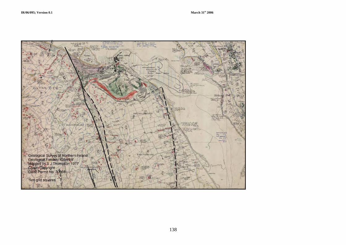
IR/06/095; Version 0.1 March 31st 2006
138

IR/06/095; Version 0.1 March 31st 2006
139
Appendix 2 Comparison of gamma ray and sonic logs for the Permian and Triassic Larne halites in the Larne No. 2 borehole
Gamma ray
0 – 100 API
Interval Transit Time
(microseconds per foot) 140 40
140 40 Interval Transit Time
(microseconds per foot)
Gamma ray
0 – 100 API
Larne halite
Permian halite

IR/06/095; Version 0.1 March 31st 2006
140
Appendix 3 Incidents at underground gas storage facilities A number of high profile incidents have led to the sudden and occasionally explosive release of stored natural gas at various sites around the world, most notably in the USA. The following section, therefore, serves to outline briefly the nature of the incidents, what was found to be the cause and their relevance to the Northern Ireland situation.
European salt cavern storage incidents leading to cavern closure The following descriptions summarise European examples of gas leaks at salt cavern facilities and instances of cavern closure arising from instability and volume loss, with no gas leaks. However, it should be noted that examples exist around the world of depressurized cavities that have remained stable for decades. For example, in the 1950s, a lenticular cavern with a roof span 366 metres was excavated by solution mining in the Bryan Mound salt dome in Texas, a site of the later Strategic Petroleum Reserve. It was constructed at an average depth of 550 metres, and a height of 55 metres. After excavation, it was filled with LPG but subsequently lost wellhead pressure and was abandoned, empty. Thirty years later, measurements indicated that the cavern was remarkably stable, having lost only about 4 percent of it total volume. (Serata, 1984; Thoms and Gehle, 2000).
Frankenthal, West Germany
In the late 1970s and early 1980s, Saar-Ferngas operated an underground natural gas storage facility at Frankenthal, West Germany. Reports of an incident involving the escape of gas from the facility are vague, with reference to large underground tanks and ‘underground chambers in soft rock and sand layers’ (AEA, 2005). That said it appears that some 16 million m3 of natural gas was being stored at a depth of circa 680 m and 70 bar (1015 psi), in what may have been an aquifer storage facility.
The incident started on 30th September 1980, when drilling operations close by the facility encountered gas that immediately started to escape. Water and mud were pumped into the well in an attempt to stop the escaping gas but proved unsuccessful. Over the next few days, the leak was eventually halted when a 14 tonne valve was fitted to an underground pipe, finally being brought under control on the 16th October. Indications are that the drilling activities had damaged an existing pipe to the underground ‘storage chamber’.
Fortunately, the escaping gas never caught fire, but gas losses were estimated at 16 million m3, valued at the time at 10 m DM or 5 million dollars (AEA, 2005).
Teutschenthal, East Germany
At Bad Lauchstädt near Teutschenthal, to the SW of the city of Halle, Germany, an underground storage facility was developed in a salt cavern within the Zechstein (Permian) Stassfurt Rock Salt (Katzung et al., 1988). Hereabouts halokinesis has led to markedly variable salt thicknesses with large salt pillows formed. Overlying the Zechstein salt is up to 400 metres of ‘Bunter’ (Triassic) sandstones (the Volpriehausen Sandstone) and a thin Quaternary cover, comprising Pleistocene sands and gravels with marly till. The salt cavern, used to store ethylene, was located in the region of thicker salt and was approximately 150 m high, the top being at circa 550 m below ground and the base at just below 700 m.
On March 29th 1988, approximately one hour prior to the eruptions seen at surface, a rapid loss of pressure in the salt cavern was detected. The first eruption and release of a mixture of ethylene and water occurred about 50 m away from well #5. It was followed by several more in parallel rows that formed a 2 km long NW trending line of emissions. At the same time, eruptions also

IR/06/095; Version 0.1 March 31st 2006
141
occurred about 250 m south of well #5, in the vicinity of well #6. The incident occurred in an area of generally sparsely populated agricultural land and an area of approximately 8 km2 was evacuated whilst the situation was monitored. The ventings of ethylene continued for several days, decreasing in intensity until the pressure in the cavern had reduced and between 60% and 80% of the product had escaped. The migrating ethylene/water mix once near surface caused doming of the ground, leading to cracks in buildings and tilting of concrete road slabs. Circular and elongated craters and fissures developed as the mix escaped to the air. However, it was decided not to evacuate parts of Teutschental town.
Investigations revealed that the cavern remained intact and that there had been no failure of the well casing at that level (Katzung et al., 1988). Ethylene was found in a drinking water well close by, which suggested leakage into an aquifer at depths of between 100 and 140 m. A faulty well casing connection at 111.8 m was subsequently found, which had allowed direct inflow of the ethylene into the lower part of the Volpriehausen Sandstone aquifer overlain by an impermeable horizon. From here the escaping ethylene, migrated laterally up-dip to the WNW until it encountered a reverse fault, which formed a vertical barrier and effectively ponded the ethylene, which then continued to migrate upwards to the NW. Eventually it breached the overlying caprock and escaped into the upper part of the Triassic Volpriehausen Formation aquifer, through which it rapidly migrated laterally to the base of the Pleistocene deposits, aided it would seem by linear zones of disruption within the aquifer. Continued inflow and rising pressures caused doming of the Pleistocene deposits until finally the mixture of water, ethylene and entrained boulder clay broke through to ground surface, creating the linear series of both circular and elongated craters.
Tersanne, France
Between November 1968 and February 1970, a pear-shaped cavern, referred to as Te02 (Bérest and Brouard, 2003), was leached in salt deposits at Tersanne in SE France. This represented the first such storage facility in France (Thoms and Gehle, 2000). The top of the cavern was at circa 1395 m with the bottom at approximately 1500 m, although significant insolubles collected at the bottom of the cavern, such that the effective base of ‘free’ cavern space was at around 1470 m. The initial usable volume was 91,000 m3 +/- 2700 m3 (Bérest and Brouard, 2003). Dewatering and filling of the cavern commenced in May 1970 and was completed by November 1970. The cavern operated for nine years, during which time the average pressures were high, but operation of the cavern meant frequent and significant pressure variations (Bérest and Brouard, 2003). Such operating conditions resulted in a 30-35% volume reduction by July 1979.
Presently, Gaz de France operates salt cavern storage facilities at depths of 1400 m in the same salt deposits of the Tersanne area. Around 14 storage wells are in operation, with gas stored at pressures of between 80 and 240 bar and providing 204 mcm3 working gas volume.
Kiel, Germany
A gas storage cavern (Kiel 101) was leached out in impure halite deposits (haselgebirge facies) of Permian age at depths between 1305 m and 1400 m at Kiel in Germany (Coates et al., 1981). The high insolubles content of the halite meant that of the initial 68 000 m3 volume, the effective volume was reduced to 32,000 m3. Pumping to remove brine from the cavern commenced in November 1967 and roof breaks were noted after only 5 days (Bérest and Brouard, 2003). After 35 days operation, a volume loss of 12% (down to 32,100 m3) was noted following sonar scans, decreasing by another 6% (1900 m3) over the next 5 months.
The cavern was operated at between 80-100 bar pressure until at least 1971.
American and Canadian salt cavern storage incidents
In the USA, solution-mined salt caverns have, for many years, been used for storage by the petrochemical industry. More recently they have been used for the storage of natural gas and liquefied petroleum gases (propane and butane). Figures released by the Energy Information

IR/06/095; Version 0.1 March 31st 2006
142
Administration (http://tonto.eia.doe.gov/dnav/ng/ng_stor_cap_dcu_nus_a.htm) show that in 2003, there were 391 underground natural gas storage facilities in operation in the United States. Of these, 30 (c. 8%) were salt cavern facilities.
Two types of salt deposits of three different ages occur in the USA and Canada, namely bedded salt and salt domes. The former occur in layers in a number of basins across the USA and into Canada, bounded on the top and bottom by (often impermeable) competent rock formations. In Canada salt was deposited during Devonian times in the Western Canada Sedimentary Basin, forming the Lotsberg and Prairie evaporite formations. These have been extensively exploited, as have the most wide spread bedded salts in the USA, which are of Permian age. These deposits contain significant quantities of impurities and interbedded with variously impermeable anhydrite, shale, and dolomite beds. The Middle Jurassic Louann Salt (e.g. Seni and Jackson, 1983) is a thick bedded, homogenous halite deposited from hypersaline waters that developed in restricted marine basins across much of the area of the present day Gulf of Mexico, including onshore Texas, Louisiana and Mississippi (Jackson and Seni, 1983; Seni and Jackson, 1983; Wescott and Hood, 1994).. These basins developed during late Triassic-Early Jurassic rifting, as the North American Plate drifted away from the African and South American plates.
The Louann Salt reaches thicknesses in excess of 1500 m in the basin centre and has led to the second type of salt deposit; salt domes or salt diapirs. These structures are most abundant in the East Texas and Gulf Coast area. The salt first moved during the early period of basin formation (Jurassic-Early Cretaceous) and continued to move at different times subsequently.
American incidents involving storage facilities constructed in Mid-Jurassic Louann salts of the American Gulf Coast area
Eminence, Louisiana (USA)
Located in Covington County, Mississippi, the Eminence salt dome represents a large salt piercement structure, the top of which lies at about 745 m below ground level (Halbouty, 1979). Strictly, the Eminence facility is not associated with any release of gas, but is included here as it experienced loss of volume due to salt creep, which led to its closure.
In 1970, following extensive studies, Transcontinental Gas Pipe Line Corporation selected the Eminence Salt Dome, as the location for the first solution-mined salt cavern storage facility constructed specifically for the storage of natural gas in the USA (Allen, 1972). The site was chosen because the dome was near to Transco’s natural gas pipeline, the salt was relatively shallow, there was a ready supply of freshwater with which to leach the salt and the Wilcox Sands provided an aquifer for brine disposal.
Two caverns between 1740 m and 2050 m apart, each with capacities of just over 1,100,000 bbl, were constructed using solution wells, which were spudded in August and November 1968. Leaching operations were completed by January 1969. A further two caverns followed, to provide a storage volume of 8892 MMscf (Coates et al., 1981).
The caverns, each served by a single well, were operated “brine free”, i.e. no brine was present in the cavern, natural gas having been injected into the caverns under pressure. Gas was withdrawn from the caverns due to the pressure, not by pumping brine into the cavern. Maximum operating storage pressure was around 3,950 psi, although well casing and shoe assembly was tested to 5000 psi, whilst wellhead equipment with 5,000 psi working pressure was installed. Minimum operating pressures were around 1000 psi.
In 1970, cavern tops were at around 1725 m (5500 feet) and the bases at about 2000m (6300 feet). By 1972 the cavity bottom in cavern #1 had risen by some 46 m (152 feet), with a total closure of 40% of the initial volume in just two years (Baar, 1977; Bérest and Brouard, 2003).
The facility operated for over 10 years, but the loss of cavern capacity eventually led to its closure in the early 1980s. The cause of the volume loss was due to having operated at pressures too low to maintain cavern walls.
IR/06/095; Version 0.1 March 31st 2006
143
Petal City, Mississippi (USA)
The Petal City natural gas storage facility is located near Petal City in Forrest County, Mississippi (EIA, 1995). At 2004, it was operated by Petal Gas Storage LLC (a subsidiary of GulfTerra Energy Partners, LP) with a contract to provide Southern Natural Gas with storage space. The facility, with interconnectors to the Tennessee Gas Pipeline, Gulf South Pipeline and Hattiesburg Gas Storage facility, comprises at least 7 caverns providing 9.5-10 billion cubic feet of high-deliverability natural gas storage and 35,400 horsepower of compression (Energy Pipeline News, 2001, 2004). The top of the salt is around 530 m below ground level (Halbouty, 1979) and the caverns have been used to store natural gas for over 30 years, operating in brine compensated mode (gas is injected/withdrawn as brine is removed/replaced).
On the 25th August 1974, liquefied butane gas was being pumped into the cavern with displaced brine moved to an open pond for storage. A miscalculation in the cavern volume amounting to 2190 tonnes (circa 106 US gallons), led to the cavern being overfilled, although the amount that eventually escaped is not known. As the gas replaced the brine in the well, pressure was lost, allowing high velocity escape of butane, which quickly formed a flammable cloud 2 kms (1.25 miles) in diameter (AEA, 2005).
Sometime after the release of butane, there was a small explosion and a fire, which caused convection and mixing of the cloud and air column. This led to a second explosion, some 240 m – 305 m above the ground, which damaged houses up to 275 m away and shattered windows up to 11 kms (7 miles) away (AEA, 2005). The fire burnt for 5 hours before the well was controlled by pumping brine into it and closing the valves. In all, 24 people were injured and around 3000 evacuated during the incident (Hirschberg et al., 1998; AEA, 2005).
West Hackberry, Louisiana (USA)
Located near Lake Charles in southern Louisiana, the West Hackberry salt dome was known as early as 1902. The top of the dome is at around 545 m below ground level (Halbouty, 1979). The salt deposits have provided brine for the local chemical industry and in 1977, a number of the resulting caverns were acquired by the US Department of Energy (DOE) for the SPR. The first crude oil delivered to the SPR on July 21, 1977 was stored at the West Hackberry storage site, which now has 22 caverns capable of providing 219 mmbbl storage space.
On September 21st 1978, during work on one of the wells servicing the Number 6 cavity (it was serviced by more than one well in order to speed up operations), there was a sudden release of an estimated 72,000 bbl of oil, which caught fire, killing one of the crew. The oil geyser continued until the pressure in the cavern had declined significantly (Bérest and Brouard, 2003). A DOE report into the accident (1980) concluded that it arose as a result of work to repair a leak in the outer casing of the well completion and re-inforcing wellhead equipment. This required withdrawal of an inner pipe and installation of a packer to seal off the cavern. During the work, however, the packer moved and was then pushed to the surface by the pressure of the oil. This led to the sudden and violent release of the cavern contents, the release of which and the associated oil geyser, continued until the pressure reached zero.
The investigation and safety reports concluded that any future work of this nature should be done when cavern pressures are lower and the wellhead pressure is zero. The incident serves to illustrate that the highest risks at cavern storage facilities result from special operations, rather than during normal operations (Bérest and Brouard, 2003).
Mont Belvieu (aka Barbers Hill), Chambers County, Texas (USA)
The Mont Belvieu gas storage facility is closely linked to the Barbers Hill oilfield discovered in April 1916 and developed in association with a salt dome near Mont Belvieu, approximately thirty miles northeast of Houston. The salt dome has served as an underground storage facility in more recent years, with solution-mined caverns constructed to store liquid propane gas for the area's numerous refineries.

IR/06/095; Version 0.1 March 31st 2006
144
The salt dome has a diameter of approximately 1600 m (1 mile). It arises from mobilisation of the Jurassic Louann Salt at depth and has raised an oval-shaped area up to 14 metres above the level and caused radial faulting of the rocks pierced by the salt dome. In 1955 Warren Petroleum Company commenced construction of underground storage caverns and a gas terminal. Twenty-six caverns with a capacity of 43 mmbbls of propane, butane, ethane, natural gas and other NGL liquids were built making it the largest such facility for NGLs in North America. Today, many other companies operate similar facilities in the area. Over 126 active solution-mined caverns storing between 75 and 300 mmbbls of hydrocarbon products, making this the world's largest storage site for petrochemicals and potentially volatile hydrocarbons.
On September 17th 1980, a drop in pressure was recorded in one of the cavities holding liquified petroleum gas, due to an underground gas leak. The gas migrated into the foundations of a house in the area and was ignited on October 3rd when a spark from an electrical appliance (believed to be a dishwasher) triggered an explosion. In the days following, gas appeared elsewhere, forcing 75 families from their homes for almost six months.
The cause of the initial leak was traced to corroded casing in a well that dated from 1958 (Bérest et al., 2001). The low-density propane and ethane rose through the cement outside the casing and then through porous rocks, faults and joints.
The 1980 explosion was followed by numerous other gas related incidents in the area over the years. In October 1984, several million dollars damage to property was caused following a further fire and explosion at the storage complex. This was followed by another explosion and fire in November 1985. On this occasion, two people were killed and the town's entire population of more than 2,000 residents were evacuated.
Following these incidents, more than 200 homeowners and several churches within 800 feet of an underground storage well accepted buyouts as part of an eventual settlement with a nine-member industry consortium.
Other incidents related to the gas storage operations in the area include: an ethylene leak that closed Texas (route) 146 running through the town; a pipeline rupture that led to a gas leak and explosion in December 2000, which destroyed a home and released a large gas cloud some 50 feet into the air. There were reports the explosion caused several minor injuries, the evacuation of about 40 homes and the diversion of airplane flights around the area. There are also reports of explosions at two underground storage wells that burned for 43 days, and a major fire at Warren Petroleum Company when two workers were killed with many acres of land scorched.
Underground propane storage incident, Houston, Texas
An incident resulting in an explosion and fire at an underground propane storage well site is reported by Gebhardt et al. (1996). Personnel from Well Control Operations (WCO), specialising in fire fighting and well control attended the scene and brought the situation under control using less conventional capping methods. Neither the location or date of the incident is released in the articles, however, it is believed to have been at Houston, Texas in 1993 as the WCO website (http://www.wildwell.com/Firefighting/ff_na4.htm) makes reference to the novel use of coiled tubing in this well capping operation, as referred to in Gebhardt et al. (1996).
The accident occurred at an underground LPG storage terminal in which two salt caverns were serviced by two wells, which were originally drilled as oil exploration wells in the 1950s. They were then used to inject water to leach the caverns and then as the injection and withdrawal wells for the storage facility. The caverns, almost certainly constructed in the Jurassic Louann Salt, extend from 360 m to 750 m below ground level (1200-2500 ft), with production string casing set at 483 m (1584 ft) and tubing string to 732 m (2400 ft). Hydrostatic pressure at the bottom of the tubing string was 1.040 psi (Gebhardt et al., 1996).
Investigations revealed the incident resulted from a leak in one of the well casings that went undetected, permitting the escape of the stored propane from one cavern, in which there was

IR/06/095; Version 0.1 March 31st 2006
145
circa 13 million gallons stored. The propane migrated through the overburden via shallow sandy soil horizons reaching the surface up to 30 m from the well, where it found an ignition source and ignited. Some of the propane collected in a shallow sand from which water had been drawn during leaching operations. This well also ignited and burned during the incident.
Initially, it was thought that work on a storage well had led to fracturing of the salt, which had allowed communication between the two caverns. Further investigations pointed to nitrogen pressure testing having raised the pressure in one cavern, which caused the casing leak at a shallow depth in the old oil well (Bérest and Brouard, 2003).
Brenham, Texas (USA)
The Brenham salt dome, known since around 1915, lies on the Washington-Austin county border in Texas, with the top of the salt occurring at around 350 m below ground level (Halbouty, 1979). The Wesley storage facility near Brenham, Texas, is an unmanned 52 acre site that in 1992 was owned and operated remotely from Tulsa, Oklahoma by an affiliate of the Seminole Pipeline Company; MAPCO Natural Gas Liquids Inc. (MNGL). The site was subject to a major incident in April 1992.
The cavern at the centre of the incident is something less than 810 m (2702 ft) below ground level with a height of at least 50 m, based upon the length of the cemented casing linking the cavern to the surface, and the tubing for injection of the product being 860 m (2871 ft) long (Bérest and Brouard, 2003. At this facility, caverns were operated such that as product was injected, then brine was withdrawn, being stored in two above ground brine ponds. Well heads were equipped with shut-down valves.
The National Transportation Safety Board investigated the incident (NTSB, 1993a) and found a sequence of events and failures of procedures that led to the release of product and a series of explosions and a fire. Early in the morning of April 7th, 1992 operations to inject LPG into a cavern commenced, which were ultimately to lead to a blast, registering 4+ on the Richter Scale in Houston (Thoms and Gehle, 2000), and which was heard 100 miles away and felt 160 miles away. The blast left three people dead, 23 others injured, destroyed twenty six homes within 1.5 miles of the explosion and damaged a further 33 homes. The ensuing fire scorched an area of 8 million square feet. (NTSB, 1993a and b, 2006; Thoms and Gehle, 2000; Gruhn, 2003).
The NTSB investigation found that the explosion was caused when liquefied gas overfilled the storage cavern and pushed its way to the surface, pouring into an adjoining brine pit. Two valves in a brine sensing line were closed at the time of the accident, meaning that sensors were unable to pick up increased pressure as the gas moved up the main line. The valves had probably been shut down during a maintenance review several weeks before the accident. No backup system was in place to allow for human error. Once above ground, the LPG turned rapidly to vapour and being heavier than air, formed a low-lying cloud several hundred yards long and rising to 20-30 feet high. A spark of unknown origin, but most likely from a passing car, triggered the explosion.
MNGL and the parent company (Seminole) were found to have failed to incorporate fail-safe features in the facility's wellhead safety system. The cause of the overfilling was the inadequacy of procedures for managing cavern storage. It was found there had been some enlargement of the cavern due to the use of undersaturated brine and the company believed the cavern to be holding 288,000 barrels (circa 45,800 m3) of liquid. However, the safety audit following the explosion suggested that the figure was nearer to 332,000 barrels (circa 52,500 m3). The cavern was therefore filled beyond its capacity. Other contributory factors found were the lack of federal and state regulations governing the design and operation of underground storage systems and inadequate emergency response procedures.
Following the explosion, the LPG storage cavern passed a mechanical integrity test (Thoms and Gehle, 2000) and the operator applied to re-open the facility with an increased capacity. Almost two years after the blast, permission was refused and the Texas Railroad Commission, which regulates the oil and gas industry for the state, ordered that the facility be shut down

IR/06/095; Version 0.1 March 31st 2006
146
permanently. The company fought the closure, losing several appeals and the site now operates as a pump station for pipelines. The cavern is empty.
A lawsuit brought by victims of the blast eventually resulted in a jury award of $5.4 million in compensatory damages and $138 million in punitive damages.
Stratton Ridge, Freeport, Texas (USA)
The Stratton Ridge salt dome in Brazoria County near Freeport, Texas, was discovered in 1913. It represents a typical Gulf Coast salt dome (Applin, 1925), the top of which is at around 381 m (1250 ft) below ground level (Halbouty, 1979).
Caverns in the salt dome have been used to store LPG for many years (Halbouty, 1979). These include the caverns referred to as the Stratton Ridge Facilities, which in 2004 were owned by Dow Hydrocarbon and Resources, who were leasing them to Kinder Morgan Energy Partners L.P. The facility has a combined capacity of 11.8 billion cubic feet of natural gas, working natural gas capacity of 5.4 billion cubic feet and a peak day deliverability of up to 400 million cubic feet per day (http://www.kindermorgan.com/investor/kmp_2004_annual_report_financials.pdf).
In the early 1990s, a salt cavern was commissioned as a natural gas storage facility at the Stratton Ridge salt dome. However, the cavern had to be abandoned when, during testing, it failed a mechanical integrity test, having leaked gas whilst being pressured up for storage (Hopper, 2004).
Magnolia, Grand Bayou, south Louisiana (USA)
The Magnolia salt dome is located in a sparsely populated area at Napoleonville, about two miles from Grand Bayou, south Louisiana. In 2003, a cavern gas storage facility was constructed in the dome, operated by Entergy Kock. On Christmas Day 2003, only six weeks after operations began at the facility, around 30 people were forced from their homes by a natural gas leak that led to the release of about 350 mmcf of gas in a matter of hours.
Investigations revealed that the gas escaped from a crack in the casing of a well near the top of a cavern, some 440 m (1,450 ft) below the surface. It was eventually plugged at a point below the crack and four other wells were drilled in the area to monitor and control the release of leaked gas that was bubbling up from underground.
Moss Bluff, Texas (USA)
The Moss Bluff salt dome, located in Liberty County about 40 miles northeast of Houston Texas, was known as long ago as 1926 (Halbouty, 1979). It is a typical Gulf coast salt dome with a rim syncline developed. The top of the salt lies at around 330 m below ground level and the base at depths greater than 3 km.
The development of the salt dome has led to the region being dotted with man-made caverns and representing one of the world’s largest storage sites for hydrocarbons. The Moss Bluff gas storage facility, comprising three separate underground caverns in a 640-acre site, is operated by Duke Energy Gas Transmission and represents an important component in the regional production, storage and shipping of natural gas. An onsite compressor station pumps natural gas into and out of the caverns through wellhead assemblies on each of the caverns. There are related facilities to facilitate transportation and/or holding of those materials and piping for natural gas, freshwater and salt water (brine). The operation of the caverns is brine compensated (brine is withdrawn from the cavern as gas is injected).
In August 2004, an incident occurred at cavern #1, the top of which is approximately 760 m (2,500 ft) below ground level and is circa 427 m (1,400 ft) high. For several days prior to the incident, cavern #1 was operating in “de-bringing mode” when brine was being brought to the surface and pumped to a surface holding pond. At the same time compressed gas was being injected into the cavern. Monitoring of brine-gas levels before the incident indicated that the

IR/06/095; Version 0.1 March 31st 2006
147
brine/gas interface at the time was at 1132 m (3714 ft), some way from the bottom of the well string.
At just after 4 am on 19th August 2004, a leak in a pipe led to a sudden gas release from cavern #1. The resultant explosion and fire caused the closure of roads and forced dozens of residents from their homes within a one-mile radius, although no one was reported injured. Another valve that could possibly have been used to turn off the flow of gas was too hot to reach. A second explosion occurred the following day and the evacuation zone was expanded to 3 miles, with local press reports suggesting the total number evacuated to be around 360. The fire remained above ground throughout the incident and for safety reasons was allowed to burn itself out. It was eventually extinguished 6½ days later at 9:15 p.m. on August 25th, when a blowout prevention valve was successful installed. During this incident, the safety and integrity of the two other storage chambers at the facility was never threatened.
Detailed investigations by Duke Energy and consultants subsequently revealed a series of events responsible for the uncontrolled gas release and resultant fire. There was an initial separation and breach of the 8 5/8-inch well string inside the cavern at, or above, the 1135 m (3,724 ft) level. The reason for this breach remains unknown as the affected materials could not be recovered from the cavern. However, records indicated that, only 10 days prior to the incident, the well string showed no signs of a separation. The breach permitted high pressure gas to displace the brine the well was carrying, which was then able to enter the well string, reach the surface and flow into the 8-inch above ground brine piping. The emergency shutdown (ESD) system in place on the 8-inch brine piping off the wellhead assembly was designed to close on the detection of a change in pressure, flow and/or composition. The ESD operated properly, however, the sudden surge of flow acted like a “water hammer” and caused the 8-inch piping between the wellhead and the ESD valve to rupture. This rupture occurred at a location in the piping that had general wall loss due to internal corrosion. The extent of the internal corrosion of the brine piping was not expected due to the relatively short period of time it had been in service (it was installed and tested in 2000). The incident was prolonged when the extreme heat of the fire blew off the entire wellhead assembly early on Friday, 20th August. For about 28 seconds the fire appeared to have been extinguished, but gas escaping through the 20-inch production casing once more re-ignited and burned until finally being extinguished on the 25th August.
The investigations concluded that the operating procedures were adequate and appropriately followed. Valve positions were confirmed and found to be correct. A thorough review of operator logs and employee interviews revealed no evidence for procedural or human error having contributed to the incident.
American incidents involving storage facilities constructed in Permian salts
Salt deposits of Permian age are found across central America and have long been used for brine extraction and the construction of cavern storage facilities. More than 600 solution mined salt caverns exist in Kansas, many of which are used for the storage of natural gas liquids (NGLs) and refined liquid products. In Kansas, the salts form the Hutchinson Salt Member of the Wellington Formation, separating the Lower and Upper Wellington shales. The Hutchinson Salt Member can be up to 215 m thick and in general, occurs as a series of distinct salt beds with interbedded mudstones and anhydrites. The Permian Ninnescah Shale between 61 m and 84 m thick conformably overlies the Wellington Formation. Permian strata are overlain by the unconsolidated Equus Beds of Pleistocene age, forming the local freshwater aquifer for much of south-central Kansas.
Leakage of stored product is reported from caverns at two facilities developed in the Hutchinson Salt Member in Kansas.
Conway, McPherson County, Kansas (USA)
Around 300 active and plugged and abandoned storage caverns are found in the Conway area. They are (or have been) used for storage since 1951, when the National Cooperative Refinery

IR/06/095; Version 0.1 March 31st 2006
148
Association started operations west of the town of McPherson, with other storage fields were developed around the town of Conway during the 1950s, 1960s and 1970s (Ratigan et al., 2002).
The Hutchinson Salt Member in the Conway district dips westwards and is typically 61 – 183 m (200 – 600 ft) thick. To the east dissolution of the salt has occurred and resulted in a zone of wet rock head, with collapse breccia formed from the overlying Upper Wellington Shale. Across this zone of wet rockhead wells encounter a loss of circulation at the top of the salt, indicating voids and in which hydrocarbons have been recorded as recently as December 2000. The overlying Ninnescah Shale is between 61 m and 84 m thick. The unconsolidated Pleistocene deposits (Equus Beds) form the local freshwater aquifer for much of south-central Kansas and can be up to 100 m thick. They do not, however, extend beneath the Conway Underground East facility; the western edge of the aquifer lies circa 1 km to the east of the site.
Records show that natural gas liquids (NGLs) and gas has been escaping from cavern facilities in the Conway area since 1956 (Ratigan et al., 2002). NGLs and gas have been encountered in both storage wells and domestic wells in and around Conway itself on at least six separate occasions between 1980 and 1981. The leaks and presence of propane and hydrocarbons in local groundwater led to several storage operators purchasing around 30 homes and relocating the residents. At the time, Kansas Department of Health and Environment also required investigations to discover the continued presence of leaking propane gas.
One of the most recent incidents occurred at the Williams Midstream Natural Gas Liquids’ Conway Underground East Storage facility. Storage of jet fuel for a nearby air force base began at the site in 1959, with extension of the facility in 1974 when operated by Home Petroleum. Williams acquired the facility in 1987 and in December 2000, NGLs were encountered in a newly drilled well at the site. Investigations were immediately launched into their presence and these indicated that large areas of the storage facility, particularly the north-central part, lie in the area affected by salt dissolution (wet rockhead). Up to 10 m of the upper salt bed is now missing, with collapse breccias forming voids into which hydrocarbons have migrated (Ratigan et al., 2002). Further occurrences of NGLs have been encountered in two shallow groundwater monitoring wells and investigations, including soil gas sampling, were ongoing to assess how and where the NGLs and gas present in the area of wet rockhead could migrate upwards into the local aquifer.
Hutchinson – aka Yaggy, Kansas (USA)
The Yaggy Storage Field lies around 7 miles NW of the town of Hutchinson, with a population of around 44,000 and provides the location for perhaps the most publicised UGS incident. At the time of the incident, the facility had about 70 wells, of which 62 were active gas storage caverns, at depths greater than 152 m (500 ft). More than 20 new wells had been drilled and were being used to create new caverns for expansion of the facility (Allison, 2001b). The wells are located on a grid with 90-120 m (300-400 ft) spacing between wells. A group of wells are connected at the surface via pipes and manifolds, allowing gas to be injected or withdrawn into all the caverns in the group simultaneously. The capacity of the Yaggy field was circa 3.2 billion cubic feet of natural gas at around 600 psi.
The Yaggy field was originally developed in the early 1980s to hold propane. The storage caverns were formed by salt dissolution using brine wells, drilled to depths between 152-274 m (500-900 ft) in the lower parts of the Lower Permian Hutchinson Salt Member of the Wellington Formation. The salt deposits are present under much of central and south-central Kansas, with salt having been mined and extracted at Hutchinson since the 1880s. The top of each cavern was located about 12 m (40 ft) below the top of the salt layer to ensure an adequate caprock that would not fracture or leak and the wells were lined with steel casing into the salt.
The Ninnescah Shale, several hundreds of feet thick, overlies the Wellington Shale Formation and is also of Permian age. Together, the Permian formations dip to the west and northwest, forming the bedrock to 15 m (50 ft) or more of the sands and gravels of the Equus Beds that

IR/06/095; Version 0.1 March 31st 2006
149
underlie the city of Hutchinson and provide the municipal water supply for the city of Hutchinson, and the city of Wichita to the east.
Decreasing financial viability eventually led to the closure of the propane storage operations in the late 1980s. The wells were cased into the salt and later plugged by partially filling them with concrete. In the early 1990s, Kansas Gas Service, a subsidiary of ONEOK of Tulsa (Oklahoma), acquired the facility and converted it to natural gas storage. The existing caverns were re-commissioned, which required drilling out the old plugged wells, whilst further wells were drilled to solution mine additional caverns.
At the time of the incident, the Yaggy facility was one of 30 “hubs” in the USA national gas distribution system and one of 27 storage fields in salt caverns nationwide. It played a key role in the supply of gas in central Kansas and was thus of national importance.
The much publicised incident On the morning of January 17, 2001, monitoring equipment registered a pressure drop in well S-1, which connected to a cavern being filled and that could hold 60 million cubic feet of gas. The operating pressure inside the cavern was normally kept at about 675 pounds per square inch (psi), but could range from 550 to 684 psi. Later that morning a gas explosion occurred in downtown Hutchinson, some seven miles distant and was followed by a series of gas and brine geysers, up to 9 m high, erupting two miles to the east along the edge of Hutchinson. The following day (18th January), a gas explosion at the Big Chief Mobile Home Park caused 2 fatalities and injured another. The city promptly ordered the evacuation of hundreds of premises: many not returning to their homes and businesses until the end of March.
An immediate investigation into the incident was set up led by the Kansas Geological Survey (e.g. Allison, 2001a and b). Chief amongst the findings was the discovery of a large curved slice in the casing of S1 at a depth of 181.4 m (595 ft - just below the top of the salt and 56 m [184 ft] above the top of the salt cavern). The damage to the casing is thought to have occurred during the re-drilling of the old cemented wells when re-opening the former propane storage facility. For at least three days the casing leak allowed natural gas at high pressure to escape and migrate upwards through the well cement and fractures in rocks above the salt. The gas reached a permeable zone formed by a thin bed of micro-fractured dolomite near the contact between the Wellington Formation and the overlying Ninnescah Shale at around 128 m (420 ft). Gypsum beds above the dolomite may have acted as seals to prevent further vertical movement of the natural gas. Pressure-induced parting along the pre-existing fracture system in the dolomite over the anticlinal crest allowed lateral migration of the gas up-dip along the crest of a narrow, low-relief, asymmetric northwesterly plunging anticline towards Hutchinson (Nissen et al., 2003 and 2004). The gas ultimately encountered old abandoned and forgotten brinewells in the Hutchinson area, which provided the pathways to the surface.
Excavations at the original downtown explosion site found a well in a basement that had been drilled to provide mineralized waters for a hotel spa. The second explosion also occurred at the site of an old abandoned brine well. The same was found to be true for the numerous gas and brine geysers to the east of the city and the gas explosion at the mobile home park. When drilled, most old brine wells were only cased down through the shallow Quaternary “Equus beds” aquifer. The deeper parts of the wells were open-hole and thus provided ready pathways for the gas to escape to the surface. It is unlikely that well casings of these old brine wells, if they exist, are sufficiently gas tight and would present problem if future leaks occurred. As many as 160 wells are thought to exist in the Hutchinson area either buried purposely or by subsequent development.
A Sedgwick County District Court jury found in 2004 that ONEOK computer operators in Tulsa overloaded the storage field caverns with natural gas, causing leaks and geological fractures that gave the gas a route underneath Hutchinson. Two local businesses destroyed by the explosions and fires were awarded $5.25 million punitive damages. The city and the state aim to locate all wells, properly plugging and abandoning them at an estimated cost that could exceed $10 million.

IR/06/095; Version 0.1 March 31st 2006
150
The incident in 2001 was not the first time that there had been problems with a cavern and well at the Hutchinson storage facility. On September 14, 1998, a shale shelf collapsed inside the field’s K-6 cavern, trapping a gamma-ray neutron instrument that had been used for monitoring purposes. Downhole video surveys revealed the casing on the verge of collapse at about 183 m (600 ft), with the camera unable to go below 205 m (674 ft), due to the blockage. In October 1998, a plan was established to remove gas from the cavern over the winter. In the spring of 1999, the radioactive tool was buried under 1.2 m (4 ft.) of concrete and the cavern’s main pipe was relined with bonding cement to block any possible leaks. The cavern is still monitored for radiation leaks.
Canadian storage cavern incident
Fort Saskatchewan, Alberta
As previously alluded to, the Saskatchewan Power Corporation constructed the first salt cavern designed specifically for the storage of natural gas at Melville, Saskatchewan, Canada. It was constructed in the Mid Devonian Prairie Evaporite salt formation at a depth of circa 1128 m (3,700 feet) with a capacity of 290,000 bbl, and came into service during 1963.
Fort Saskatchewan lies in the Interior Plains area of Canada, in the Western Canada Sedimentary Basin within which clastics, redbeds, carbonates and important salt and potash deposits of Lower to Middle Devonian age were deposited unconformably upon Precambrian or lower Palaeozoic rocks (Meijer Drees, 1994; Hamilton and Olsen, 1994). These sediments form the Elk Point Group and accumulated in topographic basins, separated by highlands, some areas of which remained emergent until late Middle Devonian times.
The salt beds form two distinct types and define the Upper and Lower subdivisions of the Elk Point Group. The Upper Elk Point contains the Prairie Evaporite salt formation, being up to 200 m thick and by far the most extensive deposit. It does, however, vary in purity within the basin. Salt also occurs as three separate and very pure deposits in the Lower Elk Point: the Lower Lotsberg, Upper Lotsberg and Cold Lake salt formations. These salts are more areally restricted but can also attain considerable thickness.
In 2001 BP Canada Energy Company were operating a natural gas liquids (NGL) plant located about 6 kilometres northeast of the City of Fort Saskatchewan, near Edmonton, Alberta. NGL products were being stored on site in underground caverns and delivered through pipelines to a number of locations in Alberta, eastern Canada, and the United States. The facility represents an important part of the Alberta NGL pipeline network.
Between August 26th and September 3rd, 2001, fire broke out at one of the ethane wells, with the fires and black smoke visible up to 50 kms away. The incident was, however, contained entirely within the BP plant site and although it caused breathing difficulties for some locals, was said to have presented no danger to the public. The incident was fully investigated and a report published by the Alberta Energy and Utilities Board (EUB, 2002) and involved Cavern 103, which was being used for the storage of ethane, an NGL product with many uses in the petrochemical industry. Cavern 103 was completed in the Lotsberg Salt Formation at a depth of about 1850 m and had a capacity of circa 127 x103 m3. At the time of the incident, there were approximately 76 x103 m3 of ethane in the cavern. The cavern had been used to store NGLs for 25 years. Wellhead and equipment configurations for this storage facility included a 2-inch connecting line between two wells some 20 m apart that were designed to be able to both produce and inject their respective fluids (103 - ethane; 103A - brine). This equalization line, with a 2-inch forged elbow near well 103A, was installed in 1977 and used during well servicing operations. It was not, however, required for the day-to-day cavern operations. Within the storage cavern, the ethane rests on the brine water and ethane injection (storage) and withdrawal (production) is achieved by coordinating well 103 and 103A operations.
Early on August 26th 2001, ethane was being pumped up well 103 by displacing the ethane in the storage cavern with brine injected into well 103A. At just after 7:00 am, an alarm from the
IR/06/095; Version 0.1 March 31st 2006
151
cavern 103 gas detector was raised in the main control room at the Fort Saskatchewan site. This was followed shortly afterwards by a second alarm from another gas detector in the area. A vapour cloud was observed in the area above cavern 103 facilities. Cavern 103 was shut in with well 103 opened to a pipeline to reduce the ethane leak. However, this failed to reduce the release rate.
The leak occurred due to failure on the exterior surface of the forged elbow on the line connecting the two wellheads. During the incident, downhole pressure dropped from 20 700 to 4400 kilopascals (kPa) over a period of six days. The resulting ethane vapour cloud enlarged and sometime after 9 am, was ignited as it came into contact with overhead power lines located within the site, creating an explosion and the resultant fire. The site was evacuated with no injuries to plant or emergency service personnel.
The flames spread to the second well, with the fire burning for over a week – mostly for safety reasons to allow the pressure in the gas cavern to reduce. By August 28th, heavy black smoke from the well fires was significantly reduced due to a combination of the ongoing fire control efforts and a reduced product flow as pressure from the ethane storage cavern declined. On August 29, it was possible to close a connecting valve between the two wellheads, greatly reducing the fire at the both wells.
In total, it is estimated that about 14 500 m3 of ethane product was lost during this incident. In the weeks immediately following, most of the plant and pipeline operations, except those involving the wells, pipelines, and ethane storage cavern associated with the incident, returned to normal.
The magnitude of the change in operating pressure of cavern 103 and the speed in the pressure change that occurred may have caused damage to the cavern; there are indications that cavern 103 now shows some signs of communication with an adjacent cavern. The ethane storage cavern remains out of operation and will do so until the EUB grant approval to resume operations.
Aquifer gas storage incidents
Spandau, western suburb of Berlin
At 9.45 am on April 23rd 2004, a gas explosion occurred at one of the Gasspeicher Berlin well sites at Spandau in the western suburbs of Berlin. Gas is stored approximately 800 m underground in an aquifer facility, which can hold 6 million cubic metres of gas, enough to supply all Berlin households for a year.
The incident appears to have occurred at a station where gas is pumped from underground storage tanks to tanker trucks. The explosion destroyed the wellhead of a monitoring well and gas escaped for about a day before the well was successfully capped. Associated Press (April 23rd, 2004) reported that the incident injured nine workers, three seriously, and forced the evacuation of some 500 residents in the western Berlin suburb. Latest details suggest that the explosion occurred while maintenance workers from Gasag were working on the store’s contents gauges, which began to leak. This storage facility is closer in design and operation to those utilising existing oil and gas reservoirs than the salt cavity types. It does however, emphasise the importance of maintaining equipment and infrastructure and correct procedures.
Chémery, France
France has a number of gas storage facilities developed in aquifers, one of the largest in Europe being operated by Gaz de France at Chémery, 120 miles SW of Paris. The facility was commissioned in 1968 and stores gas piped in from the North Sea at depths greater than 1120 m (GDF, 1996). At the time of the incident, the aquifer storage facility had a capacity of around 6.8 billion cubic metres of gas at 130 bar.
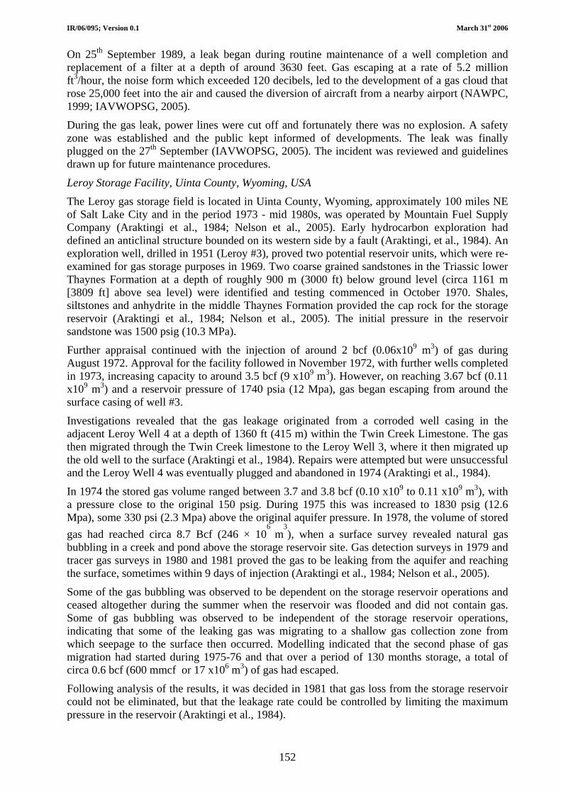
IR/06/095; Version 0.1 March 31st 2006
152
On 25th September 1989, a leak began during routine maintenance of a well completion and replacement of a filter at a depth of around 3630 feet. Gas escaping at a rate of 5.2 million ft3/hour, the noise form which exceeded 120 decibels, led to the development of a gas cloud that rose 25,000 feet into the air and caused the diversion of aircraft from a nearby airport (NAWPC, 1999; IAVWOPSG, 2005).
During the gas leak, power lines were cut off and fortunately there was no explosion. A safety zone was established and the public kept informed of developments. The leak was finally plugged on the 27th September (IAVWOPSG, 2005). The incident was reviewed and guidelines drawn up for future maintenance procedures.
Leroy Storage Facility, Uinta County, Wyoming, USA
The Leroy gas storage field is located in Uinta County, Wyoming, approximately 100 miles NE of Salt Lake City and in the period 1973 - mid 1980s, was operated by Mountain Fuel Supply Company (Araktingi et al., 1984; Nelson et al., 2005). Early hydrocarbon exploration had defined an anticlinal structure bounded on its western side by a fault (Araktingi, et al., 1984). An exploration well, drilled in 1951 (Leroy #3), proved two potential reservoir units, which were re-examined for gas storage purposes in 1969. Two coarse grained sandstones in the Triassic lower Thaynes Formation at a depth of roughly 900 m (3000 ft) below ground level (circa 1161 m [3809 ft] above sea level) were identified and testing commenced in October 1970. Shales, siltstones and anhydrite in the middle Thaynes Formation provided the cap rock for the storage reservoir (Araktingi et al., 1984; Nelson et al., 2005). The initial pressure in the reservoir sandstone was 1500 psig (10.3 MPa).
Further appraisal continued with the injection of around 2 bcf (0.06x10⁹ m3) of gas during August 1972. Approval for the facility followed in November 1972, with further wells completed in 1973, increasing capacity to around 3.5 bcf (9 x10⁹ m3). However, on reaching 3.67 bcf (0.11 x10⁹ m3) and a reservoir pressure of 1740 psia (12 Mpa), gas began escaping from around the surface casing of well #3.
Investigations revealed that the gas leakage originated from a corroded well casing in the adjacent Leroy Well 4 at a depth of 1360 ft (415 m) within the Twin Creek Limestone. The gas then migrated through the Twin Creek limestone to the Leroy Well 3, where it then migrated up the old well to the surface (Araktingi et al., 1984). Repairs were attempted but were unsuccessful and the Leroy Well 4 was eventually plugged and abandoned in 1974 (Araktingi et al., 1984).
In 1974 the stored gas volume ranged between 3.7 and 3.8 bcf (0.10 x10⁹ to 0.11 x10⁹ m3), with a pressure close to the original 150 psig. During 1975 this was increased to 1830 psig (12.6 Mpa), some 330 psi (2.3 Mpa) above the original aquifer pressure. In 1978, the volume of stored gas had reached circa 8.7 Bcf (246 × 10
6 m
3), when a surface survey revealed natural gas
bubbling in a creek and pond above the storage reservoir site. Gas detection surveys in 1979 and tracer gas surveys in 1980 and 1981 proved the gas to be leaking from the aquifer and reaching the surface, sometimes within 9 days of injection (Araktingi et al., 1984; Nelson et al., 2005).
Some of the gas bubbling was observed to be dependent on the storage reservoir operations and ceased altogether during the summer when the reservoir was flooded and did not contain gas. Some of gas bubbling was observed to be independent of the storage reservoir operations, indicating that some of the leaking gas was migrating to a shallow gas collection zone from which seepage to the surface then occurred. Modelling indicated that the second phase of gas migration had started during 1975-76 and that over a period of 130 months storage, a total of circa 0.6 bcf (600 mmcf or 17 x106 m3) of gas had escaped.
Following analysis of the results, it was decided in 1981 that gas loss from the storage reservoir could not be eliminated, but that the leakage rate could be controlled by limiting the maximum pressure in the reservoir (Araktingi et al., 1984).

IR/06/095; Version 0.1 March 31st 2006
153
The experience at the Leroy facility perfectly represents the problems encountered in aquifer storage reservoirs, which require gas injection at pressures higher than the initial value to displace water from the pores (Katz and Tek, 1981). The gas leakage was apparently related to a pressure triggered hydraulic seal failure in the reservoir cap rock (the middle Thaynes Formation).
Incidents at depleting oil and gasfields
Playa Del Rey and Los Angeles area oilfields
The Los Angeles region has been an area of intense hydrocarbon exploration and production since the latter part of the 19th Century (Chilingar and Endres, 2005). Over 70 oilfields have been discovered, most of them in the early part of the 20th Century, with hundreds of oil derricks having been drilled and blanketing the landscape. The majority of these oilfields are now abandoned, the area having been left with a legacy of old wells, the positions of which are often poorly known, but which now lie beneath densely populated urban areas. Oilfields in the Los Angeles area provide numerous instances of potentially explosive methane gas seeping to the surface and raising the possibility of a major incident. This problem has been most vividly illustrated at, for example, Fairfax (the Old Salt Lake Oilfield), Belmont (the Los Angeles City Oilfield) and Ballona Wetlands (aka Playa Vista) lying above the Playe Del Rey Oilfield (Hamilton and Meeham, 1992; Renwick and Sandidge, 2000; Chilingar and Endres, 2005).The change of land use has, therefore, inevitably led to problems.
Fairfax and Belmont gas leaks
The danger of gas seeping to the surface was demonstrated at Fairfax, LA, in March 1985, and again in 1989. In 1985, methane that had accumulated in the basement of the Ross Department Store ignited and caused an explosion that injured 23 people. Fires also broke out along surface cracks and fissures that developed nearby. The Fire Department decided to let the methane burn off over a period of many days. The escaping gas originated from the Old Salt Lake Oilfield lying immediately beneath the area and had migrated up along the Third Street Fault that reached surface beneath the department store, and at least two wells, one of which was a relatively modern inclined well that was found to be corroded below 366 m depth. The other was an old abandoned vertical well. Investigations revealed that the gas had leaked to the surface via a shallow ‘collector zone’ at around 15 m and continued to emerge through the pavement and surrounding areas whereupon it burnt for days after the explosion. High levels of gas were also found at a nearby school (Chilingar and Endres, 2005).
A very similar gas leak incident occurred on February 7th 1989 across the street from the 1985 explosion (Chilingar and Endres, 2005). The causes were found to be blocked ventilation wells and ongoing oil and gas production including corroded old wells. Quick actions and safety measures prevented a repeat of the 1985 fire and explosion. It is believed that the 1985 and 1989 Fairfax gas leaks were the result of the initiation of waste disposal or secondary recovery operations by pressure injection of oilfield wastewater back into the fields (Hamilton and Meehan, 1992). This has led to increased pressures, driving the gas out and up old wells with poorly completed or corroding and deteriorating steel casings and cements. It also periodically causes the opening of the Third Street Fault, further exacerbating the situation (Hamilton and Meehan, 1992).
A further leak and potential major hazard was detected in 1999 at the intersection of Wilshire and Curson streets just south of the La Brea Tar Pits, (which are about 1.6 km [1 mile] from the Fairfax incidents). Again, it was found that high-density commercial buildings had been developed in an area with old abandoned wells, requiring the installation of specialist ventilation equipment to prevent the build up and explosion of gas (Chilingar and Endres, 2005).
Following these incidents came the problem with the $200-million Belmont high school development, in Northwest downtown Los Angeles. Conceived in 1985 and dogged by trouble and delay, building finally commenced in 1997 but was halted by the discovery of high levels of
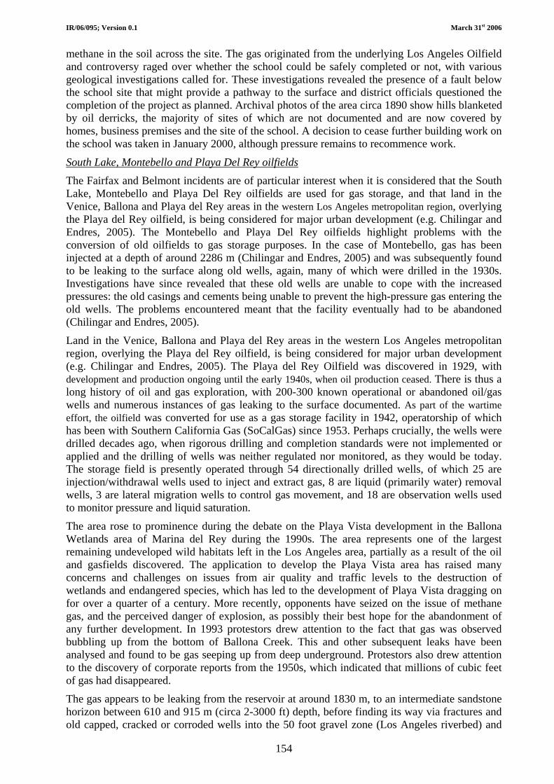
IR/06/095; Version 0.1 March 31st 2006
154
methane in the soil across the site. The gas originated from the underlying Los Angeles Oilfield and controversy raged over whether the school could be safely completed or not, with various geological investigations called for. These investigations revealed the presence of a fault below the school site that might provide a pathway to the surface and district officials questioned the completion of the project as planned. Archival photos of the area circa 1890 show hills blanketed by oil derricks, the majority of sites of which are not documented and are now covered by homes, business premises and the site of the school. A decision to cease further building work on the school was taken in January 2000, although pressure remains to recommence work.
South Lake, Montebello and Playa Del Rey oilfields
The Fairfax and Belmont incidents are of particular interest when it is considered that the South Lake, Montebello and Playa Del Rey oilfields are used for gas storage, and that land in the Venice, Ballona and Playa del Rey areas in the western Los Angeles metropolitan region, overlying the Playa del Rey oilfield, is being considered for major urban development (e.g. Chilingar and Endres, 2005). The Montebello and Playa Del Rey oilfields highlight problems with the conversion of old oilfields to gas storage purposes. In the case of Montebello, gas has been injected at a depth of around 2286 m (Chilingar and Endres, 2005) and was subsequently found to be leaking to the surface along old wells, again, many of which were drilled in the 1930s. Investigations have since revealed that these old wells are unable to cope with the increased pressures: the old casings and cements being unable to prevent the high-pressure gas entering the old wells. The problems encountered meant that the facility eventually had to be abandoned (Chilingar and Endres, 2005).
Land in the Venice, Ballona and Playa del Rey areas in the western Los Angeles metropolitan region, overlying the Playa del Rey oilfield, is being considered for major urban development (e.g. Chilingar and Endres, 2005). The Playa del Rey Oilfield was discovered in 1929, with development and production ongoing until the early 1940s, when oil production ceased. There is thus a long history of oil and gas exploration, with 200-300 known operational or abandoned oil/gas wells and numerous instances of gas leaking to the surface documented. As part of the wartime effort, the oilfield was converted for use as a gas storage facility in 1942, operatorship of which has been with Southern California Gas (SoCalGas) since 1953. Perhaps crucially, the wells were drilled decades ago, when rigorous drilling and completion standards were not implemented or applied and the drilling of wells was neither regulated nor monitored, as they would be today. The storage field is presently operated through 54 directionally drilled wells, of which 25 are injection/withdrawal wells used to inject and extract gas, 8 are liquid (primarily water) removal wells, 3 are lateral migration wells to control gas movement, and 18 are observation wells used to monitor pressure and liquid saturation.
The area rose to prominence during the debate on the Playa Vista development in the Ballona Wetlands area of Marina del Rey during the 1990s. The area represents one of the largest remaining undeveloped wild habitats left in the Los Angeles area, partially as a result of the oil and gasfields discovered. The application to develop the Playa Vista area has raised many concerns and challenges on issues from air quality and traffic levels to the destruction of wetlands and endangered species, which has led to the development of Playa Vista dragging on for over a quarter of a century. More recently, opponents have seized on the issue of methane gas, and the perceived danger of explosion, as possibly their best hope for the abandonment of any further development. In 1993 protestors drew attention to the fact that gas was observed bubbling up from the bottom of Ballona Creek. This and other subsequent leaks have been analysed and found to be gas seeping up from deep underground. Protestors also drew attention to the discovery of corporate reports from the 1950s, which indicated that millions of cubic feet of gas had disappeared.
The gas appears to be leaking from the reservoir at around 1830 m, to an intermediate sandstone horizon between 610 and 915 m (circa 2-3000 ft) depth, before finding its way via fractures and old capped, cracked or corroded wells into the 50 foot gravel zone (Los Angeles riverbed) and

IR/06/095; Version 0.1 March 31st 2006
155
thence to the surface. Furthermore, driving of piles into the poorly consolidated river terrace and wetland marsh sediments could provide more pathways for the migration of gas. Estimates for the rate of gas loss due to uncontrolled migration and/or seepage into the atmosphere at Playa Vista is put at perhaps one hundred million cubic feet per year. Gas storage in old oilfield storage facilities is thought particularly vulnerable due to leaks up the outside walls of old oil wells. Gas storage in old oilfield storage facilities is thought particularly vulnerable due to leaks up the outside walls of old oil wells. However, another major leakage route may be present in Playa Vista in that a large and previously unknown fault (the Lincoln Boulevard Fault) is now known to exist beneath the development area. The fault intersects the underground gas storage facility at a depth of 1830 m (6,000 feet) and could provide a permeable vertical pathway for the natural gas at depth to migrate to the near-surface, where it is trapped in the shallow gravel beds.
Protesters against the Playa Vista development have cited the Fairfax and Belmont incidents, highlighting the problems of gas seepages, with old wells and possible unknown faults in the area. Additionally, the Playa Vista development is being built on marshland and old river terrace deposits of the Los Angeles River, requiring pilings to be driven 50 feet into solid rock for some of the larger buildings. There is then the potential that each piling could act as a conduit, bringing methane from 50 feet below right up to the building. Consequently, the problems associated with the Playa Del Rey gas storage facility are not so much with previous high profile leaks and explosive incidents, but with the potential disasters. The Playa Vista development and associated problems clearly highlight the difficulties encountered with urban encroachment into areas historically reserved for oil and gas field operations. This is not just within the Los Angeles Basin, but anywhere with historical oil production.
Playa Del Rey gas storage incident
What is thought to have been the only incident involving the rapid escape of gas at SoCalGas’s Playa Del Rey storage facility in its 60 year history occurred on the 2nd April 2003 at around 6.10 a.m. A leak at a storage station at 8141 Gulana Ave. sprayed a mist of gas and crude oil over the local neighbourhood, coating cars, streets and homes with brown residue. Local residents described a loud rushing noise and a geyser rising up to 30 m (100 feet) into the air. Investigations found a safety mechanism was triggered when a mechanical valve in a compressor broke down. This resulted in a 25-minute venting of gas mixed with, for around 7 minutes, some accumulated oil that was present and acted as a lubricant in the transport pipes.
McDonald, Stockton, California
Sketchy reports exist for two explosions at an underground gas storage facility at McDonald, Stockton in California (e.g. Delta Protection Commission, 1997). The gas storage facility is a depleted gasfield operated by Pacific Gas and Electric (PG and E) some 360 miles north of the Los Angeles storage sites described above. The gas is stored over 1525 m (5,000 ft) below ground level and it is the largest of PG and E’s underground gas storage fields, providing approximately 25 percent of available gas supply during cold winter weather in the PG and E service area (Menconi and Sanders, 2006). Onsite there are above ground gas processing, compression and metering facilities used to inject and withdraw gas to and from the gas storage facility.
As suggested, reports are vague, but there have been two cases of explosions and fire at the facility. The first incident occurred in 1974 and the second on 1st October 1993. The second explosion was heard up to twenty miles away and resulted from an explosion in a moisture extractor, a piece of equipment that cleans the natural gas prior to injection into storage. Debris from the accident was thrown up to one-mile, causing damage to property, cars and boats in the area (Delta Protection Commission, 1997). The incident resulted in a 40% production loss and caused site damage of US$2 million and third party damage of US$50,000. The ensuing fires were extinguished by the facility's automated fire-extinguishing system.
Rough Gasfield, southern North Sea, UK Sector
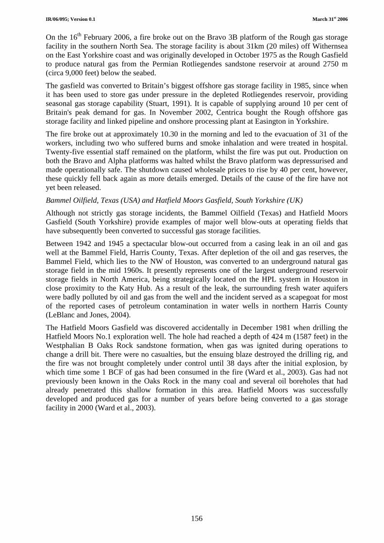
IR/06/095; Version 0.1 March 31st 2006
156
On the 16th February 2006, a fire broke out on the Bravo 3B platform of the Rough gas storage facility in the southern North Sea. The storage facility is about 31km (20 miles) off Withernsea on the East Yorkshire coast and was originally developed in October 1975 as the Rough Gasfield to produce natural gas from the Permian Rotliegendes sandstone reservoir at around 2750 m (circa 9,000 feet) below the seabed.
The gasfield was converted to Britain’s biggest offshore gas storage facility in 1985, since when it has been used to store gas under pressure in the depleted Rotliegendes reservoir, providing seasonal gas storage capability (Stuart, 1991). It is capable of supplying around 10 per cent of Britain's peak demand for gas. In November 2002, Centrica bought the Rough offshore gas storage facility and linked pipeline and onshore processing plant at Easington in Yorkshire.
The fire broke out at approximately 10.30 in the morning and led to the evacuation of 31 of the workers, including two who suffered burns and smoke inhalation and were treated in hospital. Twenty-five essential staff remained on the platform, whilst the fire was put out. Production on both the Bravo and Alpha platforms was halted whilst the Bravo platform was depressurised and made operationally safe. The shutdown caused wholesale prices to rise by 40 per cent, however, these quickly fell back again as more details emerged. Details of the cause of the fire have not yet been released.
Bammel Oilfield, Texas (USA) and Hatfield Moors Gasfield, South Yorkshire (UK) Although not strictly gas storage incidents, the Bammel Oilfield (Texas) and Hatfield Moors Gasfield (South Yorkshire) provide examples of major well blow-outs at operating fields that have subsequently been converted to successful gas storage facilities.
Between 1942 and 1945 a spectacular blow-out occurred from a casing leak in an oil and gas well at the Bammel Field, Harris County, Texas. After depletion of the oil and gas reserves, the Bammel Field, which lies to the NW of Houston, was converted to an underground natural gas storage field in the mid 1960s. It presently represents one of the largest underground reservoir storage fields in North America, being strategically located on the HPL system in Houston in close proximity to the Katy Hub. As a result of the leak, the surrounding fresh water aquifers were badly polluted by oil and gas from the well and the incident served as a scapegoat for most of the reported cases of petroleum contamination in water wells in northern Harris County (LeBlanc and Jones, 2004).
The Hatfield Moors Gasfield was discovered accidentally in December 1981 when drilling the Hatfield Moors No.1 exploration well. The hole had reached a depth of 424 m (1587 feet) in the Westphalian B Oaks Rock sandstone formation, when gas was ignited during operations to change a drill bit. There were no casualties, but the ensuing blaze destroyed the drilling rig, and the fire was not brought completely under control until 38 days after the initial explosion, by which time some 1 BCF of gas had been consumed in the fire (Ward et al., 2003). Gas had not previously been known in the Oaks Rock in the many coal and several oil boreholes that had already penetrated this shallow formation in this area. Hatfield Moors was successfully developed and produced gas for a number of years before being converted to a gas storage facility in 2000 (Ward et al., 2003).