
Applied Thermal Engineering -...
11
Research Paper Computational study of acoustic streaming and heating during acoustic hemostasis Maxim A. Solovchuk a,d,⇑ , Marc Thiriet b , Tony W.H. Sheu c,d, * a National Health Research Institutes, Institute of Biomedical Engineering and Nanomedicine, Taiwan b Sorbonne Universities, UPMC Univ Paris 06, UMR 7598, Laboratoire Jacques-Louis Lions, F-75005 Paris, France c Center of Advanced Study in Theoretical Sciences (CASTS), National Taiwan University, Taiwan d Department of Engineering Science and Ocean Engineering, National Taiwan University, No. 1, Section 4, Roosevelt Road, Taipei 10617, Taiwan highlights 3D three-field coupling physical model for investigation of acoustic hemostasis is presented. Acoustic streaming(AS) effect can reduce or completely stop the flow out of the wound. AS effect is studied for two wound shapes and different sonication angles. The study shows the theoretical possibility of sealing the bleeding site by focused ultrasound. Sonication angles between 450 and 900 should be considered in order to reduce blood flow out of the wound. article info Article history: Received 4 July 2016 Revised 5 May 2017 Accepted 8 June 2017 Available online 15 June 2017 Keywords: Acoustic hemostasis HIFU Navier-Stokes equations Acoustic streaming Westervelt equation abstract High intensity focused ultrasound (HIFU) has many applications ranging from thermal ablation of cancer to hemostasis. Although focused ultrasound can seal a bleeding site, physical mechanism of acoustic hemostasis is not fully understood yet. To understand better the interaction between different physical mechanisms involved in hemostasis a mathematical model for acoustic hemostasis is developed. This model comprises the nonlinear Westervelt equation and the bioheat equations in tissue and blood vessel. In a three dimensional domain, the nonlinear hemodynamic equations are coupled with the acoustic and thermal equations. Convective cooling and acoustic streaming effects are incorporated in the modeling study. Effect of acoustic streaming on the blood flow out of the wound has been studied for two wound shapes and different sonication angles. It was theoretically shown that if focused ultrasound beam is applied directly to the bleeding site, the flow out of the wound can be reduced due to the acoustic stream- ing effect. Bleeding can be completely stopped even for a big wound, if the focal point location, ultra- sound power and sonication angle are appropriately chosen. The sonication angles should be chosen in the range between 45° and 90°. The temperature around 70 °C can be achieved within a second on the blood vessel wall, thus showing the theoretical possibility of sealing the bleeding site by focused ultrasound. Ó 2017 Elsevier Ltd. All rights reserved. 1. Introduction Bleeding is one of the major causes of death after traumatic injuries [1]. Management of this type of injuries in 1987 in the USA, for example, accounted for $64.7 billion (in 1993 dollars) [2,3]. Hemorrhage is stopped by vessel ligation, clamping, and repair of the vessel [4,5]. Acoustic hemostasis is a new field of ultrasound research. Focused ultrasound has been successfully applied to the treatment of tumors in different areas of the bodies, including the breast, prostate, uterine fibroids and liver [6,7]. Other promising applica- tions of high intensity focused ultrasound (HIFU) include small blood vessel occlusion [8–11], hemostasis of bleeding vessels and organs [12–14]. In the latter case, the vessel wall aperture must be closed without affecting the vascular lumen to obviate both local and remote occlusions following the detachment of a blood http://dx.doi.org/10.1016/j.applthermaleng.2017.06.040 1359-4311/Ó 2017 Elsevier Ltd. All rights reserved. ⇑ Corresponding authors at: National Health Research Institutes, Institute of Biomedical Engineering and Nanomedicine, No. 35, Keyan Road, Zhunan, Taiwan and Department of Engineering Science and Ocean Engineering, National Taiwan University, Taiwan. E-mail addresses: [email protected] (M.A. Solovchuk), [email protected] (T.W.H. Sheu). Applied Thermal Engineering 124 (2017) 1112–1122 Contents lists available at ScienceDirect Applied Thermal Engineering journal homepage: www.elsevier.com/locate/apthermeng
Transcript of Applied Thermal Engineering -...
Applied Thermal Engineering 124 (2017) 1112–1122
Contents lists available at ScienceDirect
Applied Thermal Engineering
journal homepage: www.elsevier .com/locate /apthermeng
Research Paper
Computational study of acoustic streaming and heating during acoustichemostasis
http://dx.doi.org/10.1016/j.applthermaleng.2017.06.0401359-4311/� 2017 Elsevier Ltd. All rights reserved.
⇑ Corresponding authors at: National Health Research Institutes, Institute ofBiomedical Engineering and Nanomedicine, No. 35, Keyan Road, Zhunan, Taiwanand Department of Engineering Science and Ocean Engineering, National TaiwanUniversity, Taiwan.
E-mail addresses: [email protected] (M.A. Solovchuk), [email protected](T.W.H. Sheu).
Maxim A. Solovchuk a,d,⇑, Marc Thiriet b, Tony W.H. Sheu c,d,*
aNational Health Research Institutes, Institute of Biomedical Engineering and Nanomedicine, Taiwanb Sorbonne Universities, UPMC Univ Paris 06, UMR 7598, Laboratoire Jacques-Louis Lions, F-75005 Paris, FrancecCenter of Advanced Study in Theoretical Sciences (CASTS), National Taiwan University, TaiwandDepartment of Engineering Science and Ocean Engineering, National Taiwan University, No. 1, Section 4, Roosevelt Road, Taipei 10617, Taiwan
h i g h l i g h t s
� 3D three-field coupling physical model for investigation of acoustic hemostasis is presented.� Acoustic streaming(AS) effect can reduce or completely stop the flow out of the wound.� AS effect is studied for two wound shapes and different sonication angles.� The study shows the theoretical possibility of sealing the bleeding site by focused ultrasound.� Sonication angles between 450 and 900 should be considered in order to reduce blood flow out of the wound.
a r t i c l e i n f o
Article history:Received 4 July 2016Revised 5 May 2017Accepted 8 June 2017Available online 15 June 2017
Keywords:Acoustic hemostasisHIFUNavier-Stokes equationsAcoustic streamingWestervelt equation
a b s t r a c t
High intensity focused ultrasound (HIFU) has many applications ranging from thermal ablation of cancerto hemostasis. Although focused ultrasound can seal a bleeding site, physical mechanism of acoustichemostasis is not fully understood yet. To understand better the interaction between different physicalmechanisms involved in hemostasis a mathematical model for acoustic hemostasis is developed. Thismodel comprises the nonlinear Westervelt equation and the bioheat equations in tissue and blood vessel.In a three dimensional domain, the nonlinear hemodynamic equations are coupled with the acoustic andthermal equations. Convective cooling and acoustic streaming effects are incorporated in the modelingstudy. Effect of acoustic streaming on the blood flow out of the wound has been studied for two woundshapes and different sonication angles. It was theoretically shown that if focused ultrasound beam isapplied directly to the bleeding site, the flow out of the wound can be reduced due to the acoustic stream-ing effect. Bleeding can be completely stopped even for a big wound, if the focal point location, ultra-sound power and sonication angle are appropriately chosen. The sonication angles should be chosen inthe range between 45� and 90�. The temperature around 70 �C can be achieved within a second on theblood vessel wall, thus showing the theoretical possibility of sealing the bleeding site by focusedultrasound.
� 2017 Elsevier Ltd. All rights reserved.
1. Introduction
Bleeding is one of the major causes of death after traumaticinjuries [1]. Management of this type of injuries in 1987 in theUSA, for example, accounted for $64.7 billion (in 1993 dollars)
[2,3]. Hemorrhage is stopped by vessel ligation, clamping, andrepair of the vessel [4,5].
Acoustic hemostasis is a new field of ultrasound research.Focused ultrasound has been successfully applied to the treatmentof tumors in different areas of the bodies, including the breast,prostate, uterine fibroids and liver [6,7]. Other promising applica-tions of high intensity focused ultrasound (HIFU) include smallblood vessel occlusion [8–11], hemostasis of bleeding vessels andorgans [12–14]. In the latter case, the vessel wall aperture mustbe closed without affecting the vascular lumen to obviate bothlocal and remote occlusions following the detachment of a blood
HIFU
skin
bleeding site
internalorgan
Fig. 1. The schematic of acoustic hemostasis treatment.
Nomenclature
c0 speed of ultrasound in tissue, m/sci small signal sound speed increment, m/sc specific heat, J/kg �Cf ultrasonic frequency, HzF force vector per unit volume, N/m3
k wave numberkt thermal conductivity of tissue, W/m �CI sound intensity, W/m2
p acoustic pressure, N/m2
P fluid static pressure, N/m2
q ultrasound power deposition, W/m3
t time, sT temperature, �Cu blood flow velocity, m/sw velocity in z direction, m/swb blood perfusion rate, kg/m3 sx coordinate in the x directiony coordinate in the y direction
z coordinate in the z direction
Greek symbolsa absorption coefficient, Np/MHz mb nonlinearity coefficientd acoustic diffusivityk wavelength, ml shear viscosity of blood flow, kg/m sq density, kg/m3
x angular frequency, Hzs relaxation time, s
Subscriptst tissueb blood
M.A. Solovchuk et al. / Applied Thermal Engineering 124 (2017) 1112–1122 1113
clot fragment by hemodynamic force and its blockage in a down-stream vessel of smaller caliber. Therefore, the position of theultrasound focal point represents a critical aspect of acoustichemostasis. The ultrasound beam orientation and heating volumemust be carefully selected to avoid appearance of any intraluminalthrombus. Moreover, this technique is only suitable to superficialvessels.
Acoustic hemostasis is mainly studied experimentally. How-ever, the optimal strategy for the acoustic hemostasis remains tobe defined. The ultrasound frequency and intensity, exposure dura-tion, location of the focal point differ according to studies. Thefocus can be either fixed at the center of the wound or at its prox-imal or distal region. Ultrasound focus can be moved continuouslythroughout the wound. Sonication at a set of selected points can bealso carried out.
Several studies are related to punctured blood vessel [1,13,15].Under the same ultrasound parameters, the treatment time candiffer even by an order of magnitude for similar punctures [15].The difference can be attributed to the wound shape and the HIFUguidance. The ultrasound beam should be precisely located on thewound. If the location of the focal point is not properly determined,the exposure time needs to be highly increased for the same effi-ciency. In addition, physical processes should be well understoodto improve the treatment planning.
Acoustic hemostasis was also investigated numerically [16,17].Linear acoustic model was considered by the authors. However, forhigh ultrasound powers and large peak pressures used in acoustichemostasis, this assumption is not valid. At high intensities nonlin-ear wave propagation effects become important. Nonlinear propa-gation effects can enhance the local heating by several times[18,19]. Therefore in the current work nonlinear acoustic modelis considered. In Ref. [16], ultrasound propagation through differ-ent coupling materials between the biological tissues and trans-ducer during acoustic hemostasis was studied numerically.Heating in homogeneous media was considered. The temperatureincrease was modeled using the classical Pennes bioheat equation[20]. The amount of the dissipated heat was estimated by averag-ing the effect of blood perfusion over all tissues. Focused ultra-sound is able to produce hemostasis [1,13,15] in large bloodvessels up to 10 mm. For tissues with large blood vessels (diame-ters larger than 0.5 mm) Pennes bioheat equation is not valid andconvective blood flow cooling needs to be taken into account.Recently, a three-dimensional studies pointed out the influence
of blood flow and acoustic streaming on the temperature distribu-tion [18,21]. The proposed model was applied to get the tempera-ture elevation in liver tumor in a patient-specific geometry [22]. Inthe present paper the developed mathematical model is applied tothe acoustic hemostasis. Importance on the thermal and acousticstreaming effects will be addressed.
According to acoustic hemostasis experiments [13,15,23], thethermal effect exerted by focused ultrasound triggers hemostasis.The absorbed ultrasound energy in tissues is transformed intothermal energy. The resulting temperature elevation can soar upto 70 �C in about 1 s [13], thereby allowing sealing of the bleedingsite. Blood flow at the wound can in theory carry away a part of thedeposited energy. In the experiments [15], when the puncture sitewas exposed to air, a blood jet that appeared from the arterialinjury was stopped upon exposure of focused ultrasound. In mostexperimental studies, ultrasound beam is oriented roughly perpen-dicularly to the wound. In the present paper several sonicationangles and two wound shapes were studied. Sonication angleand focal point location can be optimized for bleeding arrest toreduce tissue damage and prevent thrombus risk.
2. Methods
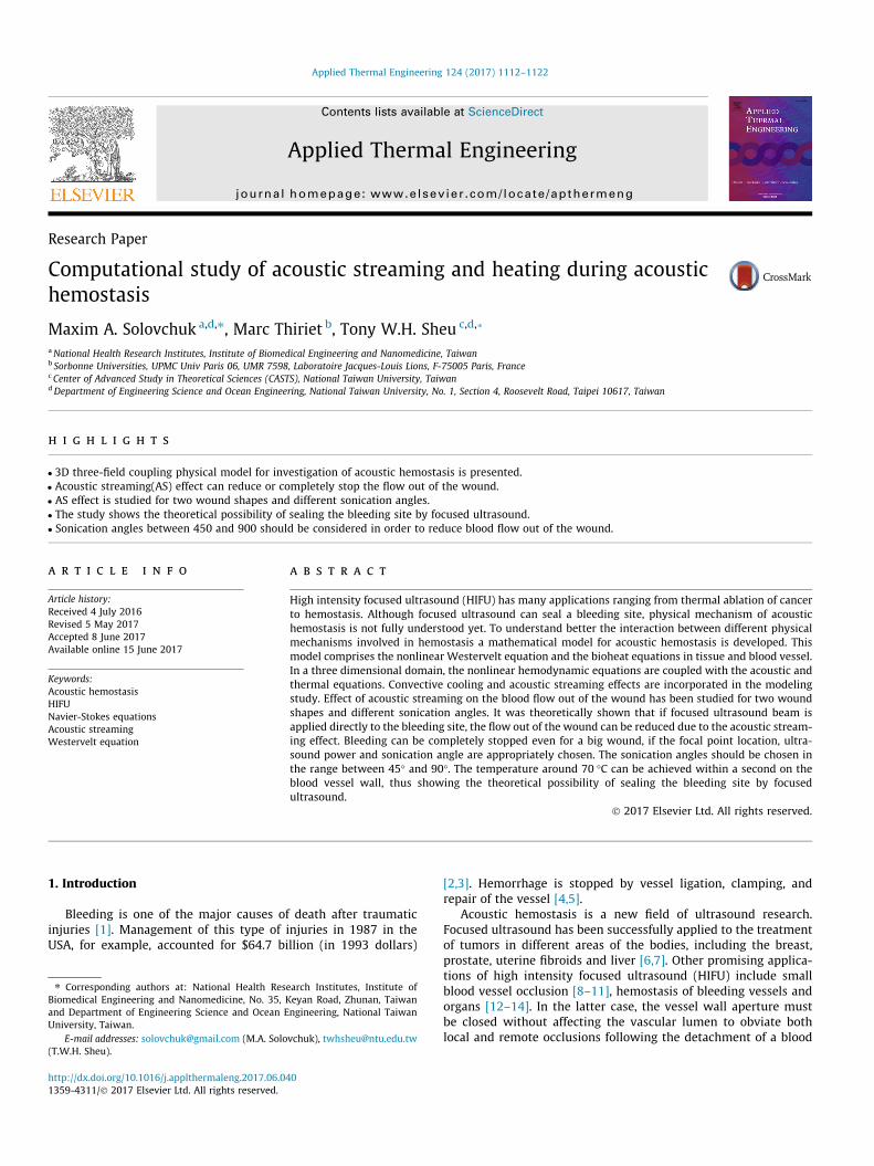
The schematic of acoustic hemostasis treatment is presented inFig. 1. Focused ultrasound device is located outside of the body.
1114 M.A. Solovchuk et al. / Applied Thermal Engineering 124 (2017) 1112–1122
There is a water layer between the transducer and the skin. Ultra-sound beam is focused at the bleeding site. Ultrasound energy canbe transformed into thermal energy and the temperature at thefocal area can be increased, which can help to seal the bleedingsite. Focused ultrasound can also induce some additional flowmotion (the effect is called acoustic streaming). Experimental stud-ies showed that acoustic streaming can sufficiently reduce or evenstop the blood flow out of the wound. However this effect is notvery well understood. In this paper we are going to study numer-ically how acoustic streaming effect can change the blood flowmotion out of the wound. For the construction of the mathematicalmodel for acoustic hemostasis it is necessary to describe acousticfield to compute the pressure and thermal fields to calculate thetemperature in tissue and blood vessel, and hydrodynamic fieldto estimate how acoustic field changes the blood flow velocity.
The three-dimensional (3D) acoustic-thermal-hydrodynamiccoupling model has been proposed to compute the pressure, tem-perature, and blood flow velocity [18]. The mathematical model[18,21] relies on the coupling of: (1) nonlinear Westervelt equationwith relaxation effects being taken into account; (2) heat equationsin biological tissues; and (3) acoustic streaming-induced hydrody-namic equations.
2.1. Nonlinear acoustic equation
Acoustic field generated by a HIFU source was modeled usingthe coupled system of two partial differential equations givenbelow [18]
r2p� 1c20
@2p@t2
þ d
c40
@3p@t3
þ b
q0c40
@2p2
@t2þXi
Pi ¼ 0
1þ si@
@t
� �Pi ¼ 2
c30cisi
@3p@t3
ð1Þ
The above system of equations takes into account the effects ofdiffraction, absorption, nonlinear propagation and relaxation. Inthe above, p is the sound pressure, b ¼ 1þ B
2A the coefficient of non-linearity, and d the diffusivity of sound originating from fluid viscos-ity and heat conduction, si the relaxation time and ci the smallsignal sound speed increment for the i-th relaxation process. Thefirst four terms in the first equation of the system (1) representthe classical Westervelt equation [24]. The new auxiliary variablePi is included to model the relaxation processes. In the presentpaper two relaxation processes (i ¼ 2) were considered.
For the linear acoustic equation the intensity is equal toIL ¼ p2=2qc0. For the nonlinear case the total intensity isI ¼P1
n¼1In, where In are the corresponding intensities for therespective harmonics nf0. The ultrasound power deposition perunit volume is calculated by
q ¼X1n¼1
2aðnf0ÞIn ð2Þ
The absorption coefficient in tissue a obeys the following frequencylaw a ¼ a0ðf=f 0Þg, where a0 ¼ 8:1 Np/m, g ¼ 1:0 and f 0 ¼ 1 MHz[25]. The unknown relaxation parameters si, ci in the differentialsystem (1) were calculated through the minimization of a meansquare error between the linear attenuation law and the relaxationmodel [18].
2.2. Radiation force and acoustic streaming hydrodynamic equations
Acoustic wave propagation in a medium exerts a force acting inthe direction of propagation, which is called the radiation force. Itcan be defined as a period averaged force acting on the medium bya sound wave. Under the linear acoustic propagation assumption,
this average force is equal to zero. So the radiation force representsthe second order nonlinear effects. Several mechanisms can con-tribute to the generation of this force, including reflection/scatter-ing at the interfaces, change of ultrasound energy during thepropagation due to the absorption and scattering [26]. Radiationforce can be used to access elastic tissue properties, for biomedicaldiagnostic applications, drug and gene delivery [27]. Good reviewabout biomedical applications of radiation force can be found in[26,28].
While ultrasound wave is propagating in the liquid, the liquidstarts moving in the direction of propagation and acoustic stream-ing appears. In the present study we are going to investigate howthe acoustic streaming effect can help to stop the bleeding. Duringacoustic hemostasis in order to seal the bleeding site, first it is nec-essary to reduce the flow out of the wound. Vaezy et al. [14] exper-imentally showed that radiation force, generated by the focusedultrasound device, was able to temporarily stop the bleeding inthe open wound. Blood jet from the puncture was stopped uponthe exposure of focused ultrasound. The ultrasound beam was per-pendicular to the blood vessel and was focused on the puncture inthe artery. It was shown that it was easier to produce hemostasiswhen the blood was pushed back by streaming. However, thetreatment time can differ by the order of magnitude for similarpunctures, ranging from ten to one hundred seconds [1,29]. Thedifference can be attributed to the wound shape, focal point loca-tion, beam orientation and ultrasound guidance. Most of the exper-imental studies considered the perpendicular orientation of bloodvessel and the ultrasound beam. In order to optimize the treat-ment, theoretical understanding of the acoustic streaming effecton the flow out of the wound is necessary. Different sonicationangles, focal point locations and wound shapes will be studied inthe present paper. It will be shown that these parameters can beoptimized during acoustic hemostasis. In the following sectionswe will show that even for the big wound with the length of6 mm, the bleeding can be completely stopped by the acousticstreaming effect, while without applying focused ultrasound about90% of mass flow comes out of the wound.
One of the first studies about acoustics streaming has been per-formed by Rayleigh [30], who studied circulation of air in Kundt’stubes. Later theoretical studies on the prediction of streamingeither in the tube or in the open domain have been performed byEckart [31], Nyborg [24,32] and Tjotta [33]. Simple analyticalexpression exists for the estimation of the streaming velocity in aplane progressive wave [33]:
v ¼ ð2aI=c0lÞð2aÞ2G;where v is the streaming velocity, l the viscosity of the medium, 2athe ultrasound beam width and G a geometric factor dependent onthe geometry of the problem. However, this analytical expressioncan be only applied for weakly focused transducers under linearacoustic approximation. However, at high intensities and at com-plex geometries nonlinear hydrodynamic equations should besolved.
In this study the flow in large blood vessels is assumed to beincompressible and laminar, for which the mass conservationequation has the form r � u ¼ 0. The equation for modeling theblood flow motion with the acoustic streaming effect being takeninto account is as follows [34,35,36]
@u@t
þ ðu � rÞu ¼ lqr2u� 1
qrPþ 1
qF ð3Þ
In the above, P is the static pressure, l (=0.0035 kg/m s) the shearviscosity of blood flow, and q the blood density. In Eq. (3), the radi-ation force vector F is assumed to act along the acoustic axis n and ithas the following form [24]
M.A. Solovchuk et al. / Applied Thermal Engineering 124 (2017) 1112–1122 1115
F � n ¼ � 1c0r~I ¼ q
c0ð4Þ
Gravity is known to significantly influence pulmonary bloodflow distribution according to the height and hence theventilation-perfusion ratio [37]. It also impacts the cerebral venousflow and the venous return in the inferior limbs in the standingposition, hence resulting in the presence of valves to counter back-flow during muscular contraction of leg skeletal muscles. In thepresent paper, the subject under consideration is in the lying posi-tion. Body forces, such as gravity and electromagnetic field, duringMRI, can nevertheless be easily added to the model.
2.3. Energy equation for tissue heating
In the current simulation study of thermal field the physicaldomain has been split into two subdomains for the perfused tissueand the flowing blood. In a region free of large blood vessels, theclassical Pennes bioheat equation [20] given below is employedto model the transfer of heat in the perfused tissue region
qt ct@T@t
¼ ktr2T �wb cb T � Tað Þ þ q ð5Þ
In the above bioheat equation q; c; k denote the density, specificheat, and thermal conductivity, respectively. The subscripts tand b refer to the tissue and blood domains. The notation Ta
denotes the arterial temperature. The variable wb (�0.5 kg/m3 s)in Eq. (5) is the perfusion rate for the tissue cooling in capillaryflows.
In the region inside the blood vessel, temperature rise was cal-culated by solving the following heat equation
qb cb@T@t
¼ kbr2T � qb cbu � rT þ q ð6Þ
where u is the blood flow velocity. In the above equation the biolog-ically relevant heat source, which is q, and the heat sink, which is�qb cbu � rT , are added to the conventional diffusion-type heatequation. It is noted here that the above thermal Eqs. (5) and (6)are coupled with the acoustic Eq. (1) for the acoustic pressurethrough the power deposition term q defined in Eq. (2). In orderto calculate the blood flow velocity u, shown on the right hand sideof Eq. (6), in a three dimensional geometry hydrodynamic equationsgiven in Eq. (3) should be solved. Focused ultrasound can induce anadditional mass flow in a fluid (acoustic streaming). The cooling dueto blood flow motion and acoustic streaming effect will be takeninto account. In Ref. [18] it was shown that in the high-intensityregime acoustic streaming velocity magnitude can be 3–30 timeslarger than the velocity in a blood vessel. Large velocity gradientscan be generated near the blood vessel wall, thereby leading tolarge shear stresses. The large shear stresses may cause damage ofthe vessel wall cells. Several experimental studies [38,39] showedthat the walls of the blood vessels were sometimes damaged afterultrasound irradiation at high powers.
2.4. Solution procedures and description of the problem
The nonlinear system of acoustic Eq. (1) is solved by the implicitfinite difference time domain method presented in [18]. The sec-ond order accurate scheme in time and sixth order accuratescheme in space are implemented for the solution of the system(1). Discretization of this system of differential equations is startedwith the approximation of the temporal derivative @
@t Pnþ1i shown in
the second equation of the system (1):
@
@tPnþ1i ¼ 1
2Dtð3Pnþ1
i � 4Pni þ Pn�1
i Þ ð7Þ
After some algebraic manipulation the second equation in the sys-tem (1) can be rewritten in the form as:
Pnþ1i ¼ 2
c30
cisi1þ 1:5si=Dt
@3pnþ1
@t3� si2Dt þ 3si
ð�4Pni þ Pn�1
i Þ ð8Þ
The above Pnþ1i is then substituted into the first equation of the sys-
tem (1).Temporal derivatives in the first equation of the system (1) are
approximated using the following second order accurate schemes:
@2p@t2
�����nþ1
¼ 2pnþ1 � 5pn þ 4pn�1 � pn�2
ðDtÞ2ð9Þ
@3p@t3
�����nþ1
¼ 6pnþ1 � 23pn þ 34pn�1 � 24pn�2 þ 8pn�3 � pn�4
2ðDtÞ3ð10Þ
The nonlinear term @2p2
@t2jnþ1 is linearized using the second order
accurate relation:
@2p2
@t2
�����nþ1
¼ @
@t@p2
@t
� �����nþ1
¼ 2@
@tpn@p
@t
����nþ1
þ pnþ1@p@t
����n
� pn@p@t
����n
!
¼ 2 2pnt p
nþ1t þ pnpnþ1
tt þ pnþ1pntt � ðpn
t Þ2 � pnpntt
� �ð11Þ
The above temporal derivatives are then substituted into the sys-tem (1) to get the Helmholtz equation. Helmholz equation is solvedimplicitly using the three-point sixth-order accurate scheme [18].Accuracy of the numerical solutions for acoustic pressure wasexamined in [18] by comparing them with the known analyticaland numerical solutions obtained by other authors [40,41]. The pre-dicted numerical results were also in good agreement with theexperimental data [18,21].
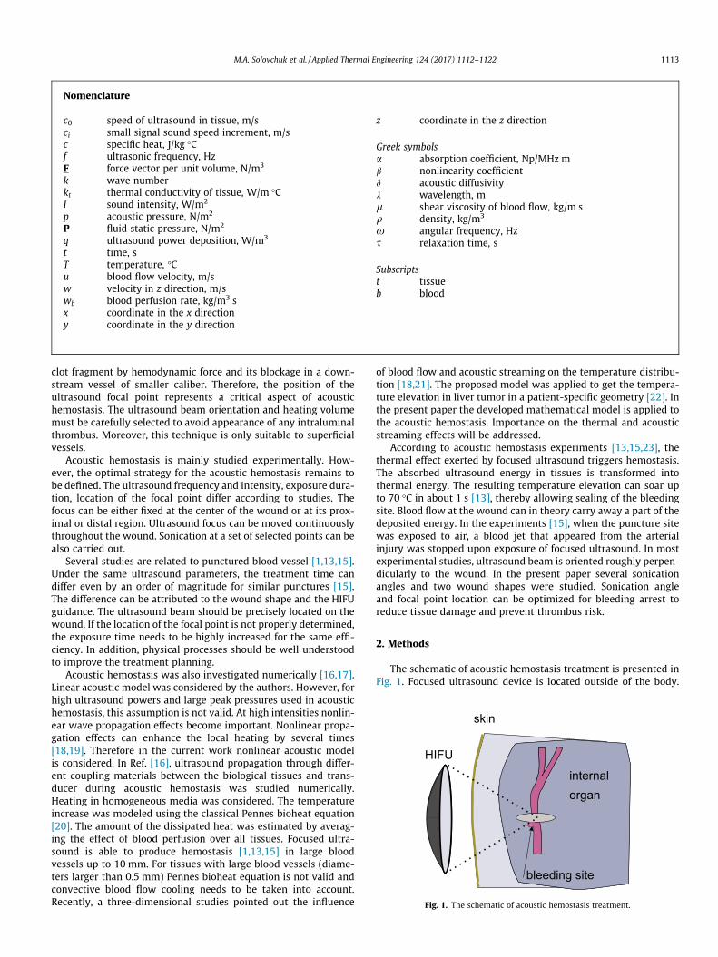
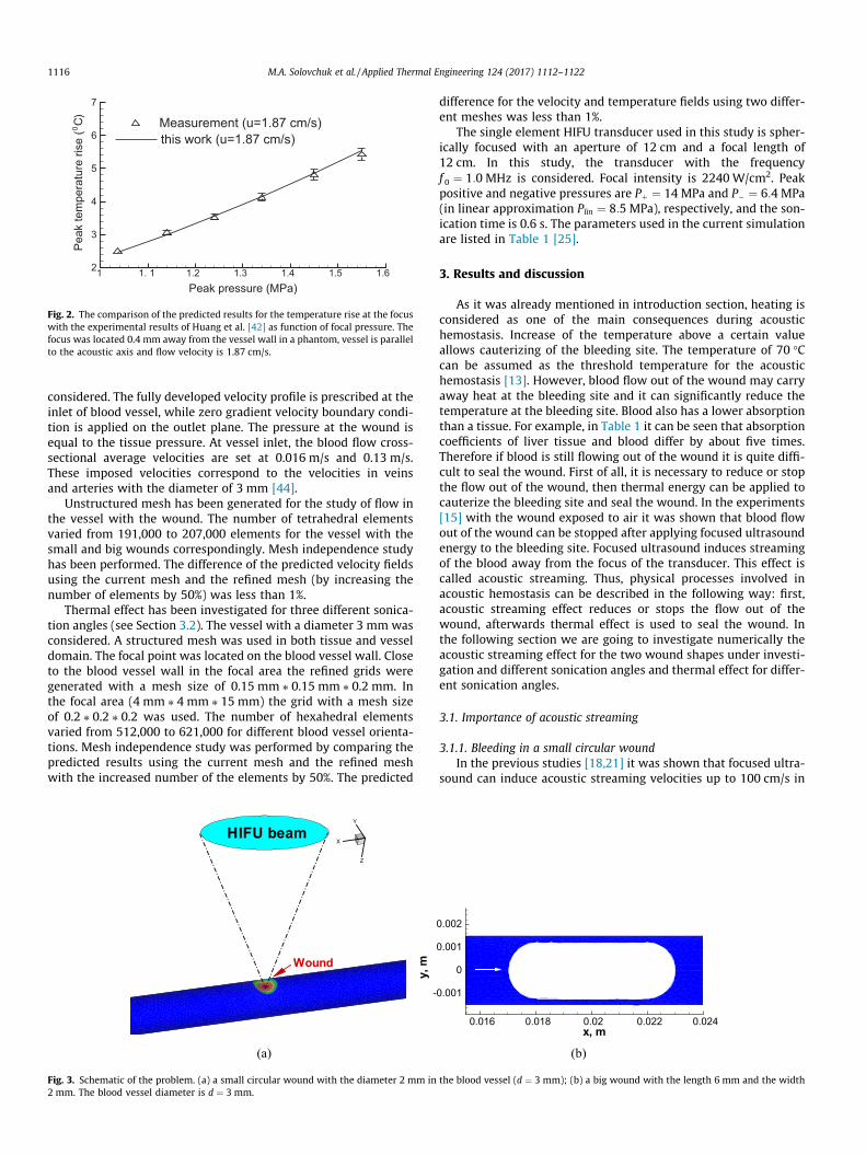
With the known acoustic pressure, the ultrasound power depo-sition in Eq. (2) and the acoustic streaming force in Eq. (4) were cal-culated. The acoustic streaming force was then substituted into Eq.(3) to compute blood flow velocity. Afterwards, temperatures inblood flow domain and in tissue were calculated. The initial tem-perature is equal to 37 �C. Finite-volume method has been appliedfor the analysis of the three-dimensional problem. A detaileddescription of the solution procedures can be found in our previousarticles [18,21,35]. The computational model for the calculation ofacoustic streaming velocity was validated by comparing the resultswith those of Kamakura et al. [36]. For the validation of the compu-tational model for the thermal field, with and without flow, thepredicted results were compared with the experimental resultsof Huang et al. [42]. Good agreement between the predicted andmeasured temperatures with and without flow has been found[42] as it can be seen in Fig. 2. We have also performed MRI mea-surements of temperature increase during focused ultrasoundtreatment in ex-vivo porcine muscle [43]. Excellent agreementbetween our numerical simulation results and experimental datahas been found [43].
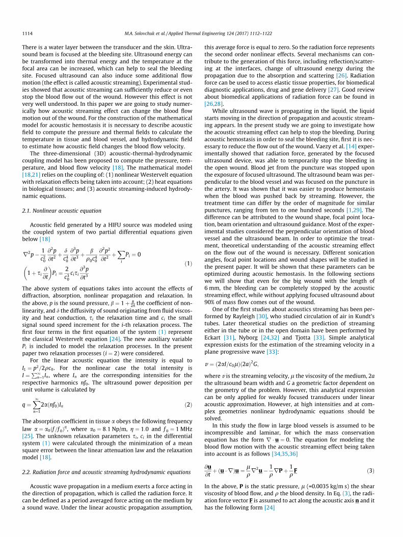
As we mentioned before, two main mechanisms of acoustichemostasis are considered in this paper: the stopping of the bloodflow out of the wound due to the radiation force (acoustic stream-ing effect) and sealing of the wound by high temperature. In orderto investigate the effect of acoustic streaming on the blood flow outof the wound, we are going to consider two different woundgeometries. Two wound shapes, namely, the small circular woundwith a diameter of 2 mm and a big long wound of 6 mm in lengthand 2 mm in width will be investigated as it can be seen in Fig. 3. Inthe present paper the vessel with a diameter of 3 mm is
1 1. 1 1.2 1.3 1.4 1.5 1.62
3
4
5
6
7
Measurement (u=1.87 cm/s)
Peak pressure (MPa)
this work (u=1.87 cm/s)
)C(
esirerutarep
metka e
P0
Fig. 2. The comparison of the predicted results for the temperature rise at the focuswith the experimental results of Huang et al. [42] as function of focal pressure. Thefocus was located 0.4 mm away from the vessel wall in a phantom, vessel is parallelto the acoustic axis and flow velocity is 1.87 cm/s.
1116 M.A. Solovchuk et al. / Applied Thermal Engineering 124 (2017) 1112–1122
considered. The fully developed velocity profile is prescribed at theinlet of blood vessel, while zero gradient velocity boundary condi-tion is applied on the outlet plane. The pressure at the wound isequal to the tissue pressure. At vessel inlet, the blood flow cross-sectional average velocities are set at 0.016 m/s and 0.13 m/s.These imposed velocities correspond to the velocities in veinsand arteries with the diameter of 3 mm [44].
Unstructured mesh has been generated for the study of flow inthe vessel with the wound. The number of tetrahedral elementsvaried from 191,000 to 207,000 elements for the vessel with thesmall and big wounds correspondingly. Mesh independence studyhas been performed. The difference of the predicted velocity fieldsusing the current mesh and the refined mesh (by increasing thenumber of elements by 50%) was less than 1%.
Thermal effect has been investigated for three different sonica-tion angles (see Section 3.2). The vessel with a diameter 3 mm wasconsidered. A structured mesh was used in both tissue and vesseldomain. The focal point was located on the blood vessel wall. Closeto the blood vessel wall in the focal area the refined grids weregenerated with a mesh size of 0.15 mm ⁄ 0.15 mm ⁄ 0.2 mm. Inthe focal area (4 mm ⁄ 4 mm ⁄ 15 mm) the grid with a mesh sizeof 0.2 ⁄ 0.2 ⁄ 0.2 was used. The number of hexahedral elementsvaried from 512,000 to 621,000 for different blood vessel orienta-tions. Mesh independence study was performed by comparing thepredicted results using the current mesh and the refined meshwith the increased number of the elements by 50%. The predicted
X
Y
Z
HIFU beam
Wound
(a)
y,m
-
Fig. 3. Schematic of the problem. (a) a small circular wound with the diameter 2 mm in2 mm. The blood vessel diameter is d ¼ 3 mm.
difference for the velocity and temperature fields using two differ-ent meshes was less than 1%.
The single element HIFU transducer used in this study is spher-ically focused with an aperture of 12 cm and a focal length of12 cm. In this study, the transducer with the frequencyf 0 ¼ 1:0 MHz is considered. Focal intensity is 2240 W/cm2. Peakpositive and negative pressures are Pþ ¼ 14 MPa and P� ¼ 6:4 MPa(in linear approximation Plin ¼ 8:5 MPa), respectively, and the son-ication time is 0.6 s. The parameters used in the current simulationare listed in Table 1 [25].
3. Results and discussion
As it was already mentioned in introduction section, heating isconsidered as one of the main consequences during acoustichemostasis. Increase of the temperature above a certain valueallows cauterizing of the bleeding site. The temperature of 70 �Ccan be assumed as the threshold temperature for the acoustichemostasis [13]. However, blood flow out of the wound may carryaway heat at the bleeding site and it can significantly reduce thetemperature at the bleeding site. Blood also has a lower absorptionthan a tissue. For example, in Table 1 it can be seen that absorptioncoefficients of liver tissue and blood differ by about five times.Therefore if blood is still flowing out of the wound it is quite diffi-cult to seal the wound. First of all, it is necessary to reduce or stopthe flow out of the wound, then thermal energy can be applied tocauterize the bleeding site and seal the wound. In the experiments[15] with the wound exposed to air it was shown that blood flowout of the wound can be stopped after applying focused ultrasoundenergy to the bleeding site. Focused ultrasound induces streamingof the blood away from the focus of the transducer. This effect iscalled acoustic streaming. Thus, physical processes involved inacoustic hemostasis can be described in the following way: first,acoustic streaming effect reduces or stops the flow out of thewound, afterwards thermal effect is used to seal the wound. Inthe following section we are going to investigate numerically theacoustic streaming effect for the two wound shapes under investi-gation and different sonication angles and thermal effect for differ-ent sonication angles.
3.1. Importance of acoustic streaming
3.1.1. Bleeding in a small circular woundIn the previous studies [18,21] it was shown that focused ultra-
sound can induce acoustic streaming velocities up to 100 cm/s in
x, m0.016 0.018 0.02 0.022 0.024
0.001
0
0.001
0.002
(b)
the blood vessel (d ¼ 3 mm); (b) a big wound with the length 6 mm and the width

X
Y
Z
Velocity, m/s
0.30.280.240.20.160.120.080.040.024
FlowHIFU beamHIFU beam
(a)
X
Y
Z
Velocity, m/s
0.260.240.20.160.120.080.040.024
FlowHIFU beamHIFU beam
(b)
Fig. 4. The predicted velocity (m/s) in vein (a) and artery (b) when the acoustic streaming effect is taken into account.
X
Y
Z
Velocity,m/s0.040.0350.0280.0250.020.0150.010.005
Flowbleeding
Flowbleeding
(a)
X
Y
Z
Velocity,m/s0.220.20.180.160.140.120.10.080.060.040.02
(b)
Fig. 5. The predicted velocity (m/s) in vein (a) and artery (b) without considering acoustic streaming effect.
Table 1Acoustic and thermal properties for the tissue and blood.
Tissue c0 ms
� �q kg
m3
� �c J
kg K
� �k W
mK
� �a Np
m
� �Tissue 1540 1055 3600 0.512 8:1fBlood 1540 1060 3770 0.53 1:5f
M.A. Solovchuk et al. / Applied Thermal Engineering 124 (2017) 1112–1122 1117
the blood vessel and can affect the ultrasound heating. When bloodvessel was placed perpendicularly to the acoustic axis, acousticstreaming velocity magnitude becomes smaller comparing withthat of the parallel blood vessel orientation.
When the focus of HIFU transducer is directed towards a bleed-ing site, the local absorption of acoustic energy supplies an extramomentum to the fluid and this force can result in streaming ofthe blood in the direction away from the focus of transducer. Usu-ally in the acoustic hemostasis experiments blood vessel waslocated perpendicularly to the acoustic axis. However it is not veryclear what blood vessel orientation is the optimal one. For the caseof big wound focal point locations and scanning paths can beplanned differently. We are therefore motivated to investigate
the effects of blood vessel orientation (sonication angle) and focalpoint location.
Let’s consider a hole (wound) on the blood vessel wall. Thediameter of this hole is 2 mm. The diameter of the blood vesselis 3 mm, and the maximum velocities are 3.2 cm/s (vein) and26 cm/s (artery). Acoustic streaming velocity magnitude is30 cm/s (without acoustic streaming the maximum velocity inthe vein is 3 cm/s). Acoustic streaming velocity magnitude is oneorder of magnitude larger than the blood flow velocity in the vein.
In Figs. 4 and 5 the velocity profiles in vein and artery are pre-sented with and without incident focused ultrasound. In Tables 2and 3 mass flow rates at the inlet and two outlets (outlet andwound) are presented in the vein and in the artery. Mass flow rate

Table 4The effect of acoustic streaming on the mass flow rate in the big wound in the vein(u ¼ 1:6 cm/s).
Mass flow rate Outlet Wound Inlet
Without AS 3% 97% 100%With AS 100% 0 100%
Table 5The effect of acoustic streaming on the mass flow rate in the big wound in the artery(u ¼ 13 cm/s).
Mass flow rate Outlet Wound Inlet
Without AS 26% 74% 100%With AS 47% 53% 100%
x, m
mas
sflo
wra
te(k
g/s)
0.017 0.018 0.019 0.02 0.021 0.022 0.0230
0.0001
0.0002
0.0003
0.0004
0.0005
0.0006
0.0007
Fig. 7. The predicted mass flow rate (kg/s) at the big wound for the cases withdifferent focal point locations, artery case.
Table 2Acoustic streaming effect on the mass flow rate in the small wound in the vein(u ¼ 1:6 cm/s).
Mass flow rate Outlet Wound Inlet
Without AS 22% 78% 100%With AS 100% 0 100%
Table 3Acoustic streaming effect on the mass flow rate in the small wound in the artery(u ¼ 13 cm/s).
Mass flow rate Outlet Wound Inlet
Without AS 55% 45% 100%With AS 71% 29% 100%
t, s
Mas
sflo
wra
te(k
g/s)
0 0.1 0.2 0.3 0.40
0.0001
0.0002
0.0003
0.0004
0.0005
0.0006
0.0007
x=0.0175 mx=0.02 m (Center)x=0.0225 m
Fig. 8. The predicted mass flow rate (kg/s) with respect to time in the wound for thecases with different focal point locations, artery case.
1118 M.A. Solovchuk et al. / Applied Thermal Engineering 124 (2017) 1112–1122
through the surface S is calculated byRR
Sq u!dS!, i.e. the flow of mass
m through a surface per unit time t. Mass flow rate at the vesselinlet is equal to 100%. Without AS, 78% of the total mass flowcomes out of the wound. If we switch the transducer, radiationforce will cause the acoustic streaming flow to occur. With theacoustic streaming effect being taken into account, the bleedingin the vein can be completely stopped. However, there is still asmall bleeding out of the artery. In the artery the blood flow outof the wound can be reduced by an amount from 45% to 29%. Inorder to stop blood flow out of the wound, higher power deposi-tions should be considered.
Simulations show that acoustic streaming velocity profilereaches the steady state within a very short time interval of0.12 s, within which bleeding can be stopped or sufficientlyreduced. This prediction is in agreement with the experimentalobservations [15,45–47]. Since the acoustic streaming velocitycan reach steady state within a very short time, only steady statevelocity contours in the present paper are plotted, unless other-wise stated.
In the next section we will show that under different sonicationangles blood flow can be stopped even in the artery.
x, m
z, m
0.014 0.016 0.018 0.02 0.022 0.024 0.026-0.001
0
0.001
0.002
0.003 Velocity, m/s0.280.240.20.160.120.080.04
Flow
(a)
Fig. 6. The predicted velocity magnitude (m/s) contours in the artery with the big wo
3.1.2. Bleeding in a big woundIn Tables 4 and 5 mass flow rates at the inlet and two outlets of
the blood vessel with a big wound are presented for the cases withand without considering acoustic streaming effect. The focal pointis located at the center of the wound. For a larger wound case it ismore difficult to stop bleeding. When we take into account theacoustic streaming effect the bleeding out of the wound in the veincan be stopped. However, there is still a flow of blood out of thewound in the artery. The blood flow out of the wound in the arteryis reduced from 74% to 53% of the total mass flow due to the acous-tic streaming effect. In Fig. 6 velocity profiles in the artery are
x, m
z, m
0.014 0.016 0.018 0.02 0.022 0.024 0.026-0.001
0
0.001
0.002
0.003Velocity, m/s
0.280.240.20.160.120.080.04
HIFUFlow
(b)
und for the cases with (right) and without (left) considering acoustic streaming.

t, s
Mas
sflo
wra
te(k
g/s)
0 0.1 0.2 0.3 0.40
0.0001
0.0002
0.0003
0.0004
0.0005
0.0006
0.0007
x=0.02 m (Center)Oscillations, 25 Hz
Fig. 9. The predicted mass flow rate (kg/s) with respect to time in the big wound fortwo cases: (1) focal point is located at the center of the wound (x ¼ 0:02) and (2)focal point is oscillating around the center of the wound with the frequency 25 Hz.
0.026
x, m
z, m
0.014 0.016 0.018 0.02 0.022 0.024-0.001
0
0.001
0.002
0.003 Velocity, m/s0.40.350.30.250.20.150.10.050
HIFUFlow
x,m
z, m
0.014 0.016 0.018 0.02 0.022 0.024-0.001
0
0.001
0.002
0.003 W, m/s0.080.050.02
-0.02-0.05-0.08-0.12-0.15-0.18
HIFUFlow
Fig. 11. The predicted velocity magnitude (m/s) contours (a and b) and stream lines (c apoint is located at the center of the wound in the artery. w - velocity component in z d
t, s
Mas
sflo
wra
te(k
g/s)
0 0.1 0.2 0.3 0.40
0.0002
0.0004
0.0006
0.0008
0.001
0.0012 angle 180angle 135angle 90angle 45angle 00
0
0
0
0
Fig. 10. The predicted mass flow rate (kg/s) with respect to time in the big woundfor the cases with different sonication angles in the artery.
t, s
mas
sflo
wra
te(k
g/s)
0.1 0.2 0.3 0.40
0.0002
0.0004
0.0006
0.0008
0.001
0.0012
angle 45_frontangle 45_rearangle 135_frontangle 135_rear
Fig. 12. The predicted mass flow rates (kg/s) with respect to time in the big woundfor the cases with different sonication angles and different locations of the focalpoint in the artery.
M.A. Solovchuk et al. / Applied Thermal Engineering 124 (2017) 1112–1122 1119
presented for the cases with and without focused ultrasound. It canbe seen that bleeding is stopped in the small focal area. This meansthat in the focal area we can seal the bleeding site by heating.
In Fig. 7 mass flow rate out of the wound is presented as thefunction of focal point location along the axis of the big wound.When the focal point is located at the rear of the wound, the largestmass flux and consequently the largest bleeding occur. When thefocal point is located close to the front of the wound(x ¼ 0:0175), the mass flux is minimal. Therefore to reduce thebleeding in the large wound, focal point should be located in frontof the wound. In Fig. 8 mass flow rate out of the wound is pre-sented with respect to time at different focal point locations.Within 0.12 s blood flow becomes steady. The smallest mass flowrate occurs at the condition when the focal point is located at thefront of the wound. The worst case happens when the focal pointis located at the rear of the wound.
Several ways of ultrasound sonications can be applied to stopbleeding in the wound. In the work of [12] mechanical scanningof HIFU probe was used to stop bleeding in a punctured artery.The frequency of the scanning was 15 or 25 Hz, the amplitude ofthe scanning was equal to the length of the wound (5–10 mm).In Fig. 9 the predicted evolution of the mass flow rate for the case
0.024x, m
z, m
0.014 0.016 0.018 0.02 0.022-0.001
0
0.001
0.002
0.003 Velocity, m/s0.350.30.250.20.150.10.050
HIFUFlow
x, m
z, m
0.014 0.016 0.018 0.02 0.022 0.024 0.026
-0.001
0
0.001
0.002
0.003 W, m/s0.160.080
-0.08-0.16-0.24
HIFUFlow
nd d) in the artery with the big wound for the sonication angles 45� and 135�. Focalirection.
0.026x, m
z, m
0.014 0.016 0.018 0.02 0.022 0.024
-0.001
0
0.001
0.002
0.003 Velocity, m/s0.40.350.30.250.20.150.10.050
HIFUFlow
(a)x, m
z, m
0.016 0.018 0.02 0.022 0.024
-0.001
0
0.001
0.002
0.003 Velocity, m/s0.40.350.30.250.20.150.10.050
HIFUFlow
(b)
Fig. 13. The predicted velocity magnitude (m/s) in the artery with the big wound for the cases with different locations of the focal point: (a) in front of the wound and (b) atthe rear of the wound. The sonication angle is 45�.
x, m
z,m
0.015 0.02 0.025-0.01
-0.005
0
0.005
T, C
70656055504540
wolF wolF
0
(a)x, m
z,m
0.015 0.02 0.025-0.01
-0.005
0
0.005
T, C
70656055504540
0
(b)x, m
z,m
0.015 0.02 0.025-0.01
-0.005
0
0.005
T, C
70656055504540
bloodvesselbloodvessel
0
(c)
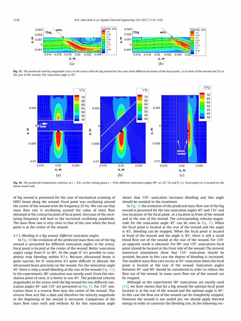
Fig. 14. The predicted temperature contours at t ¼ 0:6 s at the cutting plane y ¼ 0 for different sonication angles 90� (a), 45� (b) and 0� (c). Focal point (�) is located on theblood vessel wall.
1120 M.A. Solovchuk et al. / Applied Thermal Engineering 124 (2017) 1112–1122
of big wound is presented for the case of mechanical scanning ofHIFU beam along the wound. Focal point was oscillating aroundthe center of the wound with the frequency 25 Hz. We can see thatmass flow rate is oscillating around the value of mass flowobtained at the central location of focal point. Decrease of the oscil-lating frequency will lead to the increased oscillating amplitude.The mass flow rate is very close to that of the case when the focalpoint is at the center of the wound.
3.1.3. Bleeding in a big wound. Different sonication anglesIn Fig. 10 the evolution of the predicted mass flow out of the big
wound is presented for different sonication angles in the artery.Focal point is located at the center of the wound. Better sonicationangles range from 0� to 90�. At the angle 0� it’s possible to com-pletely stop bleeding within 0.1 s. Because ultrasound beam isquite narrow, for 0� sonication it’s quite difficult to allocate theultrasound beam precisely on the wound. For the sonication angle45� there is only a small bleeding at the rear of the wound (Fig. 11).In the experiments, 90� sonication was mostly used. From the sim-ulation point of view, it is better to use 45�. The predicted velocitymagnitudes in the artery with the big wound for two different son-ication angles 45� and 135� are presented in Fig. 11. For 135� son-ication there is a reverse flow near the center of the wound. Thisreverse flow acts like a dam and therefore the velocity magnitudein the beginning of the wound is increased. Comparison of themass flow rates with and without AS for this sonication angle
shows that 135� sonication increases bleeding and this angleshould be avoided in the treatment.
In Fig. 12 the evolution of the predicted mass flow out of the bigwound is presented for the two sonication angles 45� and 135� andtwo locations of the focal point: at a location in front of the woundand at the rear of the wound. The corresponding velocity magni-tude for the sonication angle 45� can be seen in Fig. 13. Whenthe focal point is located at the rear of the wound and the angleis 45�, bleeding can be stopped. When the focal point is locatedin front of the wound and the angle is 45�, there is still a smallblood flow out of the wound at the rear of the wound. For 135�an opposite result is obtained. For 90� and 135� sonications focalpoint should be located at the front side of the wound. The presentnumerical simulations show that 135� sonication should beavoided, because in this case the degree of bleeding is increased.The smallest mass flow rate occurs at 45� sonication when the focalpoint is located at the rear of the wound. Sonication anglesbetween 45� and 90� should be considered in order to reduce theflow out of the wound. In some cases flow out of the wound canbe stopped.
Although in the experiments 90� sonications are mostly used[15], we have shown that for a big wound the optimal focal pointlocation is at the rear of the wound and the optimal angle is 45�.In this case the flow out of the wound can be completely stopped.However the wound is not sealed yet, we should apply thermalenergy in order to cauterize the bleeding site. In the following sec-

x, m
z,m
0.016 0.018 0.02 0.022
-0.003
-0.002
-0.001
0
0.001
0.002
0.003 Velocity, m/s
0.320.280.240.20.160.120.080.04
(a)x, m
z,m
0.016 0.018 0.02 0.022 0.024
-0.002
0
0.002
0.004
Velocity, m/s0.320.280.240.20.160.120.080.04
(b)x, m
z,m
-0.002 0 0.002
0.115
0.12
0.125
0.13
Velocity, m/s
0.550.50.450.40.350.30.250.20.150.10.05
(c)
Fig. 15. The predicted acoustic streaming velocity vectors and the magnitudes contours at the cutting plane in the blood vessel without an externally applied flow (no bloodflow) for different sonication angles (a) 90�; (b) 45�; (c) and 0�. Focal point (�) is located on the blood vessel wall.
M.A. Solovchuk et al. / Applied Thermal Engineering 124 (2017) 1112–1122 1121
tion we are going to investigate the thermal effect of ultrasound fordifferent sonication angles.
3.2. Thermal effects
Let’s study the temperature distribution in the tissue and in theblood domain during acoustic hemostasis. In most of the experi-mental studies ultrasound beam was located perpendicularly tothe blood vessel. However, the optimal angle between the bloodvessel and ultrasound beam is not very clear and it is not alwayspossible to focus ultrasound beam perpendicular to the blood ves-sel. We are going to investigate how the sonication angle can affectthe temperature elevation. We assumed that acoustic streamingeffect has already stopped the flow out of the wound and the bloodvessel is intact. Focal point is located on the blood vessel wall.Blood flow velocity in the vein is 1.6 cm/s. In Fig. 14 the predictedtemperature contours at t ¼ 0:6 s are presented at the cutting
t, s
C,T
0.2 0.4 0.6 0.8
40
50
60
70
80angle 0angle 45angle 90angle 135
O
O
O
O
O
Fig. 16. The predicted temperature (�C) at the focal point as the function of time fordifferent sonication angles.
plane y ¼ 0 for three different sonication angles. We can see a verysmall temperature increase inside the blood vessel.
The predicted acoustic streaming velocity at the cutting plane inthe blood vessel without an externally applied flow is presented inFig. 15 for three different sonication angles. The acoustic streamingvelocity magnitudes are 34 cm/s, 36 cm/s and 60 cm/s for the son-ication angles 90�, 45� (or 135�) and 0� (or 180�), respectively. Theacoustic streaming velocity has the smallest value for 90� sonica-tion and the largest value for 0� sonication. For all sonicationangles, acoustic streaming velocity magnitude is up to an orderof magnitude larger than the velocity in blood vessel (1.6 cm/s invein and 13 cm/s in artery). Therefore cooling due to acousticstreaming effect can prevail over the blood flow cooling and cantherefore represent the main cooling mechanism.
In Fig. 16 the predicted temperature is presented at the focalpoint as the function of time for different sonication angles. Itcan be seen that for 90� sonication the predicted temperaturehas the largest value and for 0� sonication the predicted tempera-ture has the smallest value. For 45� and 135� sonications the pre-dicted temperatures are almost the same (about 1 �C difference),because acoustic streaming velocity magnitude (35 cm/s) is anorder of magnitude larger than the velocity in blood vessel(1.6 cm/s) and acoustic streaming is the main cooling mechanismin this case. The temperature around 70 �C on the blood vessel wallcan be reached at t ¼ 0:6 s for 90� sonication, for other sonicationangles it will take a longer time to reach the temperature 70 �C.This shows the possibility to stop bleeding theoretically. For asmaller blood vessel the effects of blood flow cooling and acousticstreaming will be smaller.
In the current subsection we assumed that there is no bloodflow coming out of the wound. In this case the temperature around70 �C can be reached quite rapidly (t < 1 s) and the wound can besealed within a short time period. Simulation shows that 90� son-ication should be chosen in order to optimize the treatment.
4. Conclusions
The mathematical model for the simulation of acoustichemostasis is proposed in the current paper. Our analysis is basedon the nonlinear Westervelt equation with the relaxation effectbeing taken into account and the bioheat equations are appliedin blood vessel and tissue domains. The nonlinear hemodynamicequation is also considered with the acoustic streaming effectbeing taken into account.

1122 M.A. Solovchuk et al. / Applied Thermal Engineering 124 (2017) 1112–1122
Both thermal and acoustic streaming effects have been investi-gated in the current paper. The importance of acoustic streamingwas examined for different blood vessel orientations and focalpoint locations. Acoustic streaming velocity magnitude is up to60 cm/s and this magnitude is several times larger than the veloc-ity in blood vessel. If focused ultrasound beam is applied directly tothe bleeding site, the flow out of a wound is considerably reduceddue to acoustic streaming. Bleeding can be even completelystopped depending on the blood vessel orientation and the focalpoint location. As a result, the wound can be quickly sealed. Simu-lations show that the temperature around 70 �C can be reachedwithin a second on the blood vessel wall, if there is no flow outof the wound. The temperature inside blood vessel remains almostunchanged. Sonication angles between 45� and 90� should be con-sidered in order to reduce blood flow out of the wound. This sim-ulation confirms the theoretical possibility of sealing the bleedingsite by means of focused ultrasound. The blood vessel remainspatent after the treatment.
Acknowledgement
The authors would like to acknowledge the financial supportfrom the Center for Advanced Study in Theoretical Sciences andfrom the Ministry of Science and Technology, R.O.C., under thegrant MOST-105-2221-E-400-005. This study was also supportedby NHRI’s project BN-104-PP-08.
References
[1] V. Zderic, A. Keshavarzi, M.L. Noble, M. Paun, S.R. Sharar, L.A. Crum, R.W.Martin, S. Vaezy, Hemorrhage control in arteries using high-intensity focusedultrasound: a survival study, Ultrasonics 44 (2006) 46–53.
[2] S. Vaezy, V. Zderic, Hemorrhage control using high intensity focusedultrasound, Int. J. Hypertherm. 23 (2007) 203–211.
[3] T.R. Miller, D.C. Lestina, Patterns in US medical expenditures and utilization forinjury, 1987, Am. J. Public Health 86 (1996) 89–93.
[4] O.M. Austin, H.P. Redmond, P.E. Burke, P.A. Grace, H.B. Bouchier, Vasculartrauma - a review, J. Am. Coll. Surg. 28 (1995) 59–70.
[5] M.O. Perry, Vascular trauma, Adv. Surgery 28 (1995) 59–70.[6] Y.F. Zhou, High intensity focused ultrasound in clinical tumor ablation, World J.
Clin. Oncol 2 (2011) 8–27.[7] T.A. Leslie, J.E. Kennedy, High intensity focused ultrasound in the treatment of
abdominal and gynaecological diseases, Int. J. Hypertherm. 23 (2007) 173–182.[8] K. Hynynen, V. Colucci, A. Chung, F. Jolesz, Noninvasive arterial occlusion using
MRI-guided focused ultrasound, Ultrasound Med. Biol. 22 (1996) 1071–1077.[9] J. Serrone, H. Kocaeli, T. Douglas Mast, M.T. Burgess, M. Zuccarello, The
potential applications of high-intensity focused ultrasound (HIFU) in vascularneurosurgery, J. Clin. Neurosci. 19 (2012) 214–221.
[10] P.W. Henderson, G.K. Lewis, N. Shaikh, A. Sohn, A.L. Weinstein, W.L. Olbricht, J.A. Spector, A portable high-intensity focused ultrasound device fornoninvasive venous ablation, J. Vasc. Surg. 51 (2010) 707–711.
[11] C.J. Shaw, J. Civale, K.J. Botting, Y. Niu, G. ter Haar, I. Rivens, D.A. Giussani, C.C.Lees, Noninvasive high-intensity focused ultrasound treatment of twin-twintransfusion syndrome: a preliminary in vivo study, Sci. Transl. Med. 8 (347)(2016) 347ra95.
[12] S. Vaezy, R. Martin, P. Kaczkowski, G. Keilman, B. Goldman, H. Yaziji, S. Carter,M. Caps, L. Crum, Use of high-intensity focused ultrasound to control bleeding,J. Vasc. Surg. 29 (1999) 533–542.
[13] S. Vaezy, R. Martin, L. Crum, High intensity focused ultrasound: a method ofhemostasis, Echocardiography 18 (2001) 309–315.
[14] S. Vaezy, R.W. Martin, U. Schmiedl, M. Caps, S. Taylor, K. Beach, S. Carter, P.Kaczkowski, G. Keilman, S. Helton, W. Chandler, P. Mourad, M. Rice, R. Roy, L.Crum, Liver hemostasis using high-intensity focused ultrasound, UltrasoundMed. Biol. 23 (1997) 1413–1420.
[15] S. Vaezy, R. Martin, H. Yazij, P. Kaczkowski, G. Keilman, S. Carter, M. Caps, E.Y.Chi, M. Bailey, L. Crum, Hemostasis of punctured blood vessels using high-intensity focused ultrasound, Ultrasound Med Biol. 24 (1998) 903–910.
[16] J.L. Teja, S.A. Lopez-Haro, L. Leija, A. Vera, A finite element simulation of highintensity focused ultrasound with polyacrylamide as coupling material foracoustic hemostasis, in: Proceedings of 2013 Pan American Health CareExchanges (PAHCE).
[17] X. Zeng, S. Mitchell, M. Miller, S. Barnes, J. Hopple, J. Kook, R. Moreau-Gobard,S. Hsu, A. Ahiekpor-Dravi, L.A. Crum, J. Eaton, K. Wong, K.M. Sekins, Acoustichemostasis of porcine superficial femoral artery: simulation and in-vivoexperimental studies, AIP Conf. Proc. 1481 (2012) 475–480.
[18] M.A. Solovchuk, T.W.H. Sheu, M. Thiriet, Simulation of nonlinear Westerveltequation for the investigation of acoustic streaming and nonlinear propagationeffects, J. Acoust. Soc. Am. 134 (2013) 3931–3942.
[19] M.A. Solovchuk, T.W.H. Sheu, M. Thiriet, Multiphysics modeling of liver tumorablation by high intensity focused ultrasound, Commun. Comput. Phys. 18(2015) 1050–1071.
[20] H.H. Pennes, Analysys of tissue and arterial blood temperature in the restinghuman forearm, J. Appl. Physiol. 1 (1948) 93–122.
[21] M.A. Solovchuk, T.W.H. Sheu, M. Thiriet, W.L. Lin, On a computational study forinvestigating acoustic streaming and heating during focused ultrasoundablation of liver tumor, J. Appl. Therm. Eng. 56 (2013) 62–76.
[22] M.A. Solovchuk, T.W.H. Sheu, M. Thiriet, Image-based computational model forfocused ultrasound ablation of liver tumor, J. Comput. Surg. 1 (2014) 4.
[23] S. Vaezy, M.L. Noble, A. Keshavarzi, M. Paun, A.F. Prokop, C. Cornejo, S. Sharar,E.Y. Chi, L.A. Crum, R.W. Martin, Liver hemostasis with high-intensityultrasound: repair and healing, J. Ultrasound Med. 23 (2004) 217–225.
[24] M.F. Hamilton, D.T. Blackstock, Nonlinear Acoustics, Academic Press, Boston,1998.
[25] F.A. Duck, Physical Property of Tissues - A Comprehensive Reference Book,Academic, London, 1990.
[26] A. Sarvazyan, Diversity of biomedical applications of acoustic radiation force,Ultrasonics 50 (2) (2010) 230–234.
[27] A. Dayton, S. Zhao, S.H. Bloch, P. Schumann, K. Penrose, T.O. Matsunaga, R.Zutshi, Application of ultrasound to selectively localize nanodroplets fortargeted imaging and therapy, Mol. Imag. 5 (3) (2006) 160–174.
[28] A.P. Sarvazyan, O.V. Rudenko, W.L. Nyborg, Biomedical applications ofradiation force of ultrasound: historical roots and physical basis, UltrasoundMed. Biol. 36 (9) (2010) 1379–1394.
[29] R.W. Martin, S. Vaezy, P. Kaczkowski, G. Keilman, S. Carter, M. Caps, K. Beach,M. Plett, L. Crum, Hemostasis of punctured vessels using Doppler-guided high-intensity ultrasound, Ultrasound Med. Biol. 25 (1999) 985–990.
[30] J.W.S. Rayleigh, On the circulation of air observed in Kundt’s tubes, and onsome allied acoustical problems, Philos. Trans. R. Soc. Lond. 175 (1884) 1–21.
[31] C. Eckart, Vortices and streams caused by sound waves, Phys. Rev. 73 (1948),676–76.
[32] W.L. Nyborg, Acoustic streaming due to attenuated plane waves, J. Acoust. Soc.Am. 25 (1953) 68–75.
[33] S. Tjotta, On some nonlinear effects in sound fields with special emphasis onthe generation of vorticity and the formation of streaming patterns, Arch.Math. Naturvidensk 55 (1959) 1–68.
[34] T.W.H. Sheu, M.A. Solovchuk, A.W.J. Chen, M. Thiriet, On an acoustics-thermal-fluid coupling model for the prediction of temperature elevation in livertumor, Int. J. Heat Mass Transfer 54 (17–18) (2011) 4117–4126.
[35] M.A. Solovchuk, T.W.H. Sheu, W.L. Lin, I. Kuo, M. Thiriet, Simulation study onacoustic streaming and convective cooling in blood vessels during a high-intensity focused ultrasound thermal ablation, Int. J. Heat Mass Transfer 55(2012) 1261–1270.
[36] T. Kamakura, M. Matsuda, Y. Kumamoto, M.A. Breazeale, Acoustic streaminginduced in focused Gaussian beams, J. Acoust. Soc. Am. 97 (1995) 2740–2746.
[37] M. Thiriet, Anatomy and Physiology of the Circulatory and VentilatorySystems, Springer, New York, 2013.
[38] G.R. ter Haar, M. Dyson, S.P. Smith, Ultrastructural changes in the mouseuterus brought about by ultrasonic irradiation at therapeutic intensities instanding wave fields, Ultrasound Med. Biol. 5 (1979) 167–179.
[39] G.R. ter Haar, Ultrasonic biophysics, in: C.R. Hill, J.C. Bamber, G.R. ter Haar(Eds.), Physical Principles of Medical Ultrasonics, John Wiley and Sons,Chichester, 2004, pp. 349–407 (chap. 12).
[40] H.T. O’Neil, Theory of focusing radiators, J. Acoust. Soc. Am. 21 (1949) 516–526.
[41] D.T. Blackstock, Connection between the Fay and Fubini solutions for planesound waves of finite amplitude, J. Acoust. Soc. Am. 14 (1966) 1019–1026.
[42] J. Huang, R.G. Holt, R.O. Cleveland, R.A. Roy, Experimental validation of atractable medical model for focused ultrasound heating in flow-through tissuephantoms, J. Acoust. Soc. Am. 116 (2004) 2451–2458.
[43] M.A. Solovchuk, S.C. Hwang, H. Chang, M. Thiriet, T.W.H. Sheu, Temperatureelevation by HIFU in ex-vivo porcine muscle: MRI measurement andsimulation study, Med. Phys. 41 (2014) 052903, http://dx.doi.org/10.1118/1.4870965.
[44] J.W. Hand, Ultrasound hyperthermia and the prediction of heating, in: F.A.Duck, A.C. Baker, H.C. Starritt (Eds.), Ultrasound in Medicine, Institute ofPhysics Publishing, Bristol, 1998 (Ch. 8).
[45] S. Harnof, Z. Zibly, A. Hananel, S. Monteith, J. Grinfeld, G. Schiff, I. Kulbatski, N.Kassell, Potential of magnetic resonance-guided focused ultrasound forintracranial hemorrhage: an in vivo feasibility study, J. Stroke Cerebrovasc.Dis. 23 (6) (2014) 1585–1591.
[46] C.J. Shaw, G.R. ter Haar, I.H. Rivens, D.A. Giussani, C.C. Lees, Pathophysiologicalmechanisms of high-intensity focused ultrasound-mediated vascularocclusion and relevance to non-invasive fetal surgery, J. R. Soc. Interf. 11(95) (2014) 20140029.
[47] R. Greaby, V. Zderic, S. Vaezy, Pulsatile flow phantom for ultrasound image-guided HIFU treatment of vascular injuries, Ultrasound Med. Biol. 33 (8)(2007) 1269–1276.


![Numericalstudyofflowfieldinducedbyalocomotivefish ...homepage.ntu.edu.tw/~twhsheu/member/paper/111-2007.pdfproblem was numerically studied by Ralph and Pedley [19], Demirdzic and](https://static.fdocuments.in/doc/165x107/611324c818cff51997455a0b/numericalstudyofiowieldinducedbyalocomotiveish-twhsheumemberpaper111-2007pdf.jpg)


