APPLIED SCIENCES AND ENGINEERING Robust...
10
APPLIED SCIENCES AND ENGINEERING 2017 © The Authors, some rights reserved; exclusive licensee American Association for the Advancement of Science. Distributed under a Creative Commons Attribution NonCommercial License 4.0 (CC BY-NC). Robust nanogenerators based on graft copolymers via control of dielectrics for remarkable output power enhancement Jae Won Lee, 1 * Hye Jin Cho, 2 * Jinsung Chun, 1 Kyeong Nam Kim, 1 Seongsu Kim, 3 Chang Won Ahn, 4 Ill Won Kim, 4 Ju-Young Kim, 1 Sang-Woo Kim, 3,5 Changduk Yang, 2† Jeong Min Baik 1† A robust nanogenerator based on poly(tert-butyl acrylate) (PtBA)–grafted polyvinylidene difluoride (PVDF) copolymers via dielectric constant control through an atom-transfer radical polymerization technique, which can markedly in- crease the output power, is demonstrated. The copolymer is mainly composed of a phases with enhanced dipole moments due to the p-bonding and polar characteristics of the ester functional groups in the PtBA, resulting in the increase of dielectric constant values by approximately twice, supported by Kelvin probe force microscopy measure- ments. This increase in the dielectric constant significantly increased the density of the charges that can be accumu- lated on the copolymer during physical contact. The nanogenerator generates output signals of 105 V and 25 mA/cm 2 , a 20-fold enhancement in output power, compared to pristine PVDF–based nanogenerator after tuning the surface potential using a poling method. The markedly enhanced output performance is quite stable and reliable in harsh mechanical environments due to the high flexibility of the films. On the basis of these results, a much faster charging characteristic is demonstrated in this study. INTRODUCTION Dielectric materials, commonly referred to as electrical insulators, have received much attention owing to their strong electron bonding, good support of electric fields, and low energy loss (1–3). In particular, the polarization and depolarization that occur in dielectrics as a result of an external electric field have been investigated as a means to efficiently charge and discharge electricity. This capability is very useful when ap- plied to capacitors ( 4–6). Dielectrics have also been widely used in many applications, such as transistors (7, 8), photovoltaic devices (9, 10), and electrical insulation (11). Recently, the triboelectric nanogenerator (TENG), which converts mechanical energy into electricity, has been suggested as a new energy-harvesting technology. Since 2012, it has been proven as a cost-effective, simple, and efficient technique for the realization of var- ious self-powered systems, such as sensors (12, 13) and charging systems (14, 15). However, greater output performance is essential for the implementation of TENG in practical applications. Although various strategies to enhance the output performance have been re- ported, an effective dielectric for creating the device with high per- formance should be developed because the output power is critically dependent on the density of the charges transferred (16, 17). To date, various dielectric materials, such as polydimethylsiloxane (PDMS) (18), poly(methyl methacrylate) (PMMA) (19), polyimide (PI) (20), polyvinylidene difluoride (PVDF) (21), and polytetrafluoroethylene (PTFE) (22), have been used without any modifications, and the re- sulting electrical signals were extremely weak. Very recently, mod- ification of properties, such as compressibility (16), surface potential (23), and hydrophobicity (24), in a few TENGs has been reported; however, most of them have focused of partial reports of the effects of output performance. The parameters mentioned above may also be interrelated to each other. Therefore, the establishment of an inter- related library for the development of dielectrics from a materials per- spective may be needed. PVDF, a dielectric polymer with a good piezoelectric/pyroelectric response and low acoustic impedance, has been considered as one of the most widely studied dielectric materials in mechanical energy– harvesting technologies. In particular, it can be formed in a variety of nanostructures, such as nanowires, nanofibers, and nanotubes, and can be flexible; therefore, the use of PVDF has been successfully demonstrated in a number of devices, such as capacitors, sensors, and TENGs (25–27). Following the principle that grafting one polymer onto another poly- mer backbone can combine the benefits of each parent polymer, we set out to design and synthesize PVDF graft copolymers to incorporate poly( tert -butyl acrylate) (PtBA) through an atom-transfer radical polymeri- zation (ATRP) technique as an efficient dielectric to enhance the output performance of the TENGs. Grafting of PtBA onto the PVDF backbone suppressed the formation of the b phases; hence, the PVDF-Gn graft co- polymers were mainly composed of a phases. As the grafting ratio in- creased to 18%, the dielectric constant values increased from 8.6 to 16.5 in the frequency ranging from 10 2 to 10 5 Hz, which was attributed to the increase of the net dipole moment of the materials, and supported by the Kelvin probe force microscopy measurements (KPFMs). The TENG fabricated with the graft copolymer generated an output voltage of 64.4 V and a current density of 18.9 mA/cm 2 , twice the enhancement in both, compared to pristine PVDF–based TENG. Further increase in the output performance to 105 V and 25 mA/cm 2 , a 20-fold enhance- ment in output power, was also obtained by tuning the surface potential with the poling method, which improved the charge-accepting charac- teristics. The enhanced output performance was quite stable and reliable in a harsh mechanical environment due to the high flexibility of the 1 School of Materials Science and Engineering, KIST-UNIST Ulsan Center for Convergent Materials, Ulsan National Institute of Science and Technology, Ulsan 44919, Republic of Korea. 2 Department of Energy Engineering, School of Energy and Chemical Engineering, Ulsan National Institute of Science and Technology, Ulsan 44919, Republic of Korea. 3 SKKU Advanced Institute of Nanotechnology, Sungkyunkwan University, Suwon 16419, Republic of Korea. 4 Department of Physics and Energy Harvest Storage Research Center, University of Ulsan, Ulsan 44610, Republic of Korea. 5 School of Advanced Materials Sciences and Engineer- ing, Sungkyunkwan University, Suwon 16419, Republic of Korea. *These authors contributed equally to this work. †Corresponding author. Email: [email protected] (C.Y.); [email protected] (J.M.B.) SCIENCE ADVANCES | RESEARCH ARTICLE Lee et al., Sci. Adv. 2017; 3 : e1602902 26 May 2017 1 of 9 on June 20, 2018 http://advances.sciencemag.org/ Downloaded from
Transcript of APPLIED SCIENCES AND ENGINEERING Robust...

SC I ENCE ADVANCES | R E S EARCH ART I C L E
APPL I ED SC I ENCES AND ENG INEER ING
1School of Materials Science and Engineering, KIST-UNIST Ulsan Center forConvergent Materials, Ulsan National Institute of Science and Technology, Ulsan44919, Republic of Korea. 2Department of Energy Engineering, School of Energyand Chemical Engineering, Ulsan National Institute of Science and Technology,Ulsan 44919, Republic of Korea. 3SKKU Advanced Institute of Nanotechnology,Sungkyunkwan University, Suwon 16419, Republic of Korea. 4Department ofPhysics and Energy Harvest Storage Research Center, University of Ulsan, Ulsan44610, Republic of Korea. 5School of Advanced Materials Sciences and Engineer-ing, Sungkyunkwan University, Suwon 16419, Republic of Korea.*These authors contributed equally to this work.†Corresponding author. Email: [email protected] (C.Y.); [email protected] (J.M.B.)
Lee et al., Sci. Adv. 2017;3 : e1602902 26 May 2017
2017 © The Authors,
some rights reserved;
exclusive licensee
American Association
for the Advancement
of Science. Distributed
under a Creative
Commons Attribution
NonCommercial
License 4.0 (CC BY-NC).
Robust nanogenerators based on graft copolymersvia control of dielectrics for remarkable outputpower enhancement
Jae Won Lee,1* Hye Jin Cho,2* Jinsung Chun,1 Kyeong Nam Kim,1 Seongsu Kim,3 Chang Won Ahn,4Ill Won Kim,4 Ju-Young Kim,1 Sang-Woo Kim,3,5 Changduk Yang,2† Jeong Min Baik1†
Dow
nloaded
A robust nanogeneratorbasedonpoly(tert-butyl acrylate) (PtBA)–graftedpolyvinylidenedifluoride (PVDF) copolymersvia dielectric constant control through an atom-transfer radical polymerization technique, which can markedly in-crease the output power, is demonstrated. The copolymer is mainly composed of a phases with enhanced dipolemoments due to the p-bonding and polar characteristics of the ester functional groups in the PtBA, resulting in theincrease of dielectric constant values by approximately twice, supported by Kelvin probe force microscopy measure-ments. This increase in the dielectric constant significantly increased the density of the charges that can be accumu-lated on the copolymer during physical contact. The nanogenerator generates output signals of 105 V and 25 mA/cm2,a 20-fold enhancement in output power, compared to pristine PVDF–based nanogenerator after tuning the surfacepotential using a poling method. The markedly enhanced output performance is quite stable and reliable in harshmechanical environments due to the high flexibility of the films. On the basis of these results, a much faster chargingcharacteristic is demonstrated in this study.
fro
on June 20, 2018http://advances.sciencemag.org/
m
INTRODUCTIONDielectric materials, commonly referred to as electrical insulators, havereceived much attention owing to their strong electron bonding, goodsupport of electric fields, and low energy loss (1–3). In particular, thepolarization and depolarization that occur in dielectrics as a result ofan external electric field have been investigated as a means to efficientlycharge and discharge electricity. This capability is very useful when ap-plied to capacitors (4–6). Dielectrics have also been widely used in manyapplications, such as transistors (7, 8), photovoltaic devices (9, 10), andelectrical insulation (11).
Recently, the triboelectric nanogenerator (TENG), which convertsmechanical energy into electricity, has been suggested as a newenergy-harvesting technology. Since 2012, it has been proven as acost-effective, simple, and efficient technique for the realization of var-ious self-powered systems, such as sensors (12, 13) and chargingsystems (14, 15). However, greater output performance is essentialfor the implementation of TENG in practical applications. Althoughvarious strategies to enhance the output performance have been re-ported, an effective dielectric for creating the device with high per-formance should be developed because the output power is criticallydependent on the density of the charges transferred (16, 17). To date,various dielectric materials, such as polydimethylsiloxane (PDMS)(18), poly(methyl methacrylate) (PMMA) (19), polyimide (PI) (20),polyvinylidene difluoride (PVDF) (21), and polytetrafluoroethylene(PTFE) (22), have been used without any modifications, and the re-
sulting electrical signals were extremely weak. Very recently, mod-ification of properties, such as compressibility (16), surface potential(23), and hydrophobicity (24), in a few TENGs has been reported;however, most of them have focused of partial reports of the effectsof output performance. The parameters mentioned above may also beinterrelated to each other. Therefore, the establishment of an inter-related library for the development of dielectrics from a materials per-spective may be needed.
PVDF, a dielectric polymer with a good piezoelectric/pyroelectricresponse and low acoustic impedance, has been considered as one ofthe most widely studied dielectric materials in mechanical energy–harvesting technologies. In particular, it can be formed in a varietyof nanostructures, such as nanowires, nanofibers, and nanotubes,and can be flexible; therefore, the use of PVDF has been successfullydemonstrated in a number of devices, such as capacitors, sensors,and TENGs (25–27).
Following the principle that grafting onepolymer onto another poly-mer backbone can combine the benefits of each parent polymer, we setout to design and synthesize PVDF graft copolymers to incorporatepoly(tert-butyl acrylate) (PtBA) through anatom-transfer radical polymeri-zation (ATRP) technique as an efficient dielectric to enhance the outputperformance of the TENGs. Grafting of PtBA onto the PVDF backbonesuppressed the formation of the b phases; hence, the PVDF-Gn graft co-polymers were mainly composed of a phases. As the grafting ratio in-creased to 18%, the dielectric constant values increased from 8.6 to 16.5in the frequency ranging from102 to 105Hz, whichwas attributed to theincrease of the net dipolemoment of thematerials, and supported by theKelvin probe force microscopy measurements (KPFMs). The TENGfabricated with the graft copolymer generated an output voltage of64.4 V and a current density of 18.9 mA/cm2, twice the enhancementin both, compared to pristine PVDF–based TENG. Further increase inthe output performance to 105 V and 25 mA/cm2, a 20-fold enhance-ment in output power, was also obtained by tuning the surface potentialwith the poling method, which improved the charge-accepting charac-teristics. The enhanced output performancewas quite stable and reliablein a harsh mechanical environment due to the high flexibility of the
1 of 9

SC I ENCE ADVANCES | R E S EARCH ART I C L E
film. A much faster charging property was also demonstrated inthis study.
on June 20, 20http://advances.sciencem
ag.org/D
ownloaded from
RESULTS AND DISCUSSIONThe PtBA-grafted PVDF copolymers were prepared with ATRP (Fig.1A), in accordance with previously established methods in the liter-ature (28). The grafting ratios were controlled as a function of var-ious reaction times (12 to 72 hours) under the same conditions,yielding three samples with a different number-average molecularmass (Mn = 180.0 to 218.5 kDa). In a careful inspection of the 1Hnuclear magnetic resonance (NMR) spectra of the samples (Fig. 1B),the composition of the graft copolymers was calculated on a molebasis from the integral ratio of two noticeable resonances at 2.3 to2.5 and 2.9 to 3.2 parts per million (ppm) attributed to head-to-headand head-to-tail configurations of PVDF and the signals at 1.4 to1.65 ppm associated with the tert-butyl group in PtBA using thefollowing equations (29)
x ¼ ðintegral1:4�1:65Þ=9ðintegral2:3�2:5 þ integral2:9�3:2Þ=2 ð1Þ
PtBA mole percent mol%ð Þ ¼ x1þ x
� 100 ð2Þ
The mole percent of PtBA in the graft copolymer was determinedas 10, 15, and 18%. Here, the graft copolymers were designatedPVDF-Gn, where Gn refers to the mole percent of PtBA grafting.In addition, as shown in Fig. 1C, the Fourier transform infrared(FTIR) spectra of the PVDF-Gn showed the appearance of the absorp-tion bands at 1725 cm−1 assigned to the stretching vibrations of theester carbonyl groups, in contrast with pristine PVDF. Also, as thegrafting ratios of PtBA were increased, we observed the graduallyenhanced intensity of the carbonyl bands relative to the methylenestretching bands of PVDF at about 1404 cm−1, which further sub-stantiates the PtBA content determined above.
As for a dielectric, the solutions were casted on a very flat SiO2/Sisubstrate with a blocking layer. After the annealing process, the film
Lee et al., Sci. Adv. 2017;3 : e1602902 26 May 2017
18
was peeled off from the substrate and glued on an Al film using aKapton film, followed by the attachment of the Al electrode tofabricate the TENG, as shown in Fig. 2 (A and B). The detailed ex-perimental procedures are also described in Materials and Methods.Figure 2B also shows that the resultant film appeared white and quiteflexible after it was peeled off. The TENG had an active area of 2 cm ×2 cm, with the spacer between the bottom electrode and the PVDF-Gnfilm made of four springs in each corner. The output voltages andcurrent densities of the TENGs were measured and plotted in Fig. 2Band fig. S1. A cycled compressive force of around 50 N at an appliedfrequency of 10 Hz was applied. The TENG with pristine PVDF filmshowed small ac-type electrical output performance of less than ap-proximately 32.9 V and 7.7 mA/cm2. For the PVDF-G10, the outputvoltage and current density were increased to 45 V and 8.3 mA/cm2,respectively. Furthermore, the highest enhancement (with an outputvoltage of 64.4 V and a current density of 18.9 mA/cm2) was observedin PVDF-G18 under the same mechanical force. To show the highoutput performance of the TENG, we used various polymers, suchas PI, PTFE, and polyvinyl chloride, as dielectrics in the TENGsand measured the electrical output performances. Figure S2 showsthat the TENGwith the PVDF-G18 film generated the largest outputvoltage and current density, compared with those with other poly-mers. The instantaneous power densities were also obtained bymeasuring the output voltages and current densities of the PVDF-G18–based TENG with external loads from 1 ohm to 1 gigohm, plotted inFig. 2C. At 10 megohms, approximately 0.45 mA/cm2 was obtained,a 20-fold enhancement in output power, compared with pristinePVDF–based TENG in fig. S3. The energy conversion efficiency ofPVDF-G18–based TENG was estimated as the ratio between theoutput energy produced by the TENG and the input energy appliedto the TENG. By considering the mass and the velocity of the toplayer, the kinetic energy (that is, the input energy) was calculatedto be 0.481 mJ. With an external load resistance of 10 megohms,the electrical energy produced by the TENG was approximately0.054 mJ. Thus, the maximum energy conversion was calculated tobe approximately 11.23%.
The transferred charge density of all samples significantly increasedwith the mole percent, showing agreement with the simulation andexperimental results in Fig. 2D and figs. S4 and S5. According to aprevious report (16), the dielectric constant of the dielectric plays avery important role in determining the electrical output performanceof the TENG. The total transferred charge density (s′) on the topelectrode of the TENG can be expressed as (30)
s0 ¼ �s0dgapdgap þ dPVDF=ePVDF
ð3Þ
where s0 is the triboelectric charge density at the equilibrium state;dgap and dPVDF are the gap distance and thickness of PVDF-basedfilms, respectively; and ePVDF is the dielectric constant of PVDF-basedfilms. According to Eq. (3), the obtained s′ can increase as the di-electric constant increases. Using the COMSOLMultiphysics software,we also calculated electrostatic potentials inside the TENG with PtBAmole percent, as shown in fig. S5. When the TENG is fully released, ifwe assume the electric potential (Ubottom) of the surfaces of the bottomlayer to be zero, the electric potential of the surfaces of the top di-electric layer (Utop) can be expressed as Utop = s′dgap/e0, where s′is the total transferred charge density, e0 is the vacuum permittivity
Fig. 1. Synthesis of PVDF-Gn graft copolymers. (A) Synthesis of PVDF-Gn graftcopolymers and photograph of the PVDF and PVDF-G18 NMP solutions. 1H NMR(B) and FTIR (C) of PVDF and PVDF-Gn.
2 of 9

SC I ENCE ADVANCES | R E S EARCH ART I C L E
on June 20, 2018http://advances.sciencem
ag.org/D
ownloaded from
of free space (8.854 × 10⁻¹² F m−1), and the gap distance (dgap) of theTENG can be assigned as dgap = 1 mm. The dielectric constant of thePVDF-Gn film was obtained from the results, measured to be 9.1 to16.5. It is clear that the potential increases with PtBA mole percent,meaning that the output power of the TENG is enhanced.
To show their practical application, we evaluated the capacitorcharging characteristic of the TENGs, which were integrated withan ac-to-dc converting circuit, as shown in fig. S6A. The convertingcircuit consists of one rectifier, three low capacitors (3 × 0.001 mF),and one capacitor (1, 2.2, 3.3, 10, 22, 33, 100, 220, 330, and 1000 mF)to convert the output signal from ac to dc. When a vertical compressiveforce of 50 N under a frequency of 10 Hz was applied, the capacitorswere charged up to approximately 4 V when a 1000-mF capacitor wasused. It was also clearly seen that the capacitor charge by the PVDF-G18–based TENG was much faster and the charged voltage was twicelarger, compared with those of pristine PVDF–based TENG (fig. S6B).
Figure 3 shows the flexibility and durability of the PVDF film–based TENG. To show this flexibility, we bent the films 3000 times,as shown in Fig. 3A, and measured the output current densities, as
Lee et al., Sci. Adv. 2017;3 : e1602902 26 May 2017
compared with those measured before the bending. As shown in Fig.3B, neither TENG exhibited a significant change in the output currentdensities before or after bending, indicating that the films are quitestable in harsh environments. The PVDF-G18–based TENG still gen-erated a higher output current than the pristine PVDF–based one. Theoutput current density generated by the PVDF-G18–based TENG alsodid not appear to change significantly at 18,000 cycles during the test.This result reveals the robustness and mechanical durability of TENGsin practical settings.
The enhancement in output power due to grafting was analyzed inmany ways because there are many factors influencing the outputpower, such as the surface roughness of the contact layers, the com-pressibility of the triboelectric materials, the dielectric properties, andthe surface potentials (16, 17, 23, 31). Furthermore, these factors maybe interrelated to each other, meaning that the main reason for theenhancement was not easy to find. First, we evaluated the surface mor-phology of the PVDF-Gn films measured using atomic force micros-copy (AFM), as shown in fig. S7A. The root mean square roughnessvalue was measured to be approximately 98.11 nm at the PVDF-G18,
Fig. 2. Fabrication of PVDF-Gn–based TENGs and its output performance. (A) Schematic diagrams of the fabrication process for the PVDF-Gn–based TENGs.(B) Photographs of a flexible PVDF-Gn film after it was peeled off and a PVDF-Gn–based TENG. (C) Output current densities generated by the PVDF-based TENGs as afunction of the PtBA mole percent ranging from 0 to 18%. (D) Output voltages, current densities, and output power densities of the PVDF-G18–based TENG with the resistanceof external loads from 1 to 109 ohms. (E) Charge densities generated by the PVDF-based TENGs as a function of the PtBA mole percent ranging from 0 to 18%. (F) Measuredvoltage of a commercial capacitor (1, 2.2, 3.3, 10, 22, 33, 100, 220, 330, and 1000 mF) charged with ac-to-dc signal converting circuit using PVDF-G18–based TENG.
3 of 9

SC I ENCE ADVANCES | R E S EARCH ART I C L E
on June 20, 2018http://advances.sciencem
ag.org/D
ownloaded from
and there was no significant change as the mole percent decreasedfrom 18 to 0%, as shown in fig. S7A. We strove to minimize the effectof the roughness by casting the solution on a very flat SiO2/Si substrateand peeling off the film to make a very flat PVDF surface because animportant factor in enhancing the output performance of the TENG isto increase its surface roughness. These results may imply that the ef-fect of the roughness on the output power is negligible.
The cross-sectional scanning electron microscopy (SEM) images ofthe PVDF-Gn films with the grafting ratio are shown in fig. S7B. Here,the thickness of all films was fixed to approximately 30 mm. All filmswere quite porous, which is most likely due to the slow solvent re-moval process at low temperature (~60°C). These porous structuresare effective in enhancing the output power because the outputperformance is significantly dependent on compressibility (16). Here,to measure the compressibility of the films, we evaluated resistance todeformation by external force using the Berkovich indenter, which in-duces a much higher local strain than uniaxial compression. Theloading and unloading curves measured by the nanoindentation teston the PVDF-based films are shown in fig. S8. The nanoindentationresults show that plastic collapse occurs in all samples during loadingand unloading. The loading-unloading curves for PVDF-based filmsshown in fig. S8A indicate their repeatable plastic deformation, withthe same displacement depth of approximately 1 mm when in uniaxialcompression. On the basis of the nanoindentation test (fig. S8B), onecan conclude that there is no change in the elastic modulus and hard-ness of PVDF-based films, meaning that the films exist with partiallyelastic recovery and not perfectly elastic recovery and are mixed via theelastic-plastic transition.
With two important factors excluded, we measured the frequency-dependent dielectric properties of the PVDF-based films over the fre-quency range of 102 to 106 Hz at room temperature, plotted in Fig. 4.To measure the dielectric constants, PVDF-based films were preparedon an Au/Si substrate, and Au as a top electrode was then depositedusing an e-beam evaporator. For the pristine PVDF film, the dielectricconstant was measured to be approximately 8.6 in the frequencyrange of 102 to 105 Hz, which is almost the same as in previous reports(32, 33). There is a significant drop in the dielectric constant in thehigher frequency range (105 to 106 Hz). This is because the dipole re-laxation of the polymers cannot catch up with the external oscillatingfield. As the grafting ratios in the backbone increased, the dielectricconstant gradually increased. In consequence, the PVDF-G18 showsa superior dielectric constant value of up to 16.5 (fig. S9). There is nosignificant change in the loss tangent (~0.03) of all samples, except
Lee et al., Sci. Adv. 2017;3 : e1602902 26 May 2017
those in the higher frequency range. This means that the dielectric con-stant values are quite reliable. In principle, the dielectric constant has astrong correlation with polarizability and free volume of the elementspresent in the materials, as formulated in the Clausius-Mossotti equa-tion (34). The p-bonding and polar characteristics of the ester groups(−COO–) in the PtBA are able to not only hold relatively great polar-izability but also increase the net dipole moment in the backbone. Theseare considered to be major factors contributing to the improvement ofdielectric constant values in the graft copolymers (34).
To investigate the relationship between the dielectric constant andoutput performance of the TENG, we compared the output currentsof PVDF-based TENGs as a function of measuring time, as plotted inFig. 5A. The output current increases with the mole percent, as alsoshown in Fig. 3. Note that the time taken for the output to reach 90%of the final current also increases with the mole percent from 3.15(±0.51) s to 14.48 (±0.58) s, as plotted in Fig. 5B. In general, in afilm-type capacitor, the accumulated charges (Q) can be expressed as
Q ¼ CV 1� e�tRC
h ið4Þ
where C, V, t, and R are the capacitance, input voltage, charging time,and resistance, respectively. Assuming that V is constant, C can becalculated using the equation C = e0erA/d, where e0, er, A, and dare the permittivity of free space (8.854 × 10⁻¹² F m−1), dielectric con-stant of the material, contact area (4 cm2), and distance (30 mm) be-tween the top and bottom electrodes, respectively. Thus, the chargescan be expressed with the dielectric constant in Fig. 5C. As the di-electric constant doubles, the charges increase by two times and thesaturation time also increases from 2.3 to 4.52 s, which agrees wellwith the experimental results. This indicates that the increase in thedielectric constant can enhance the maximum charge density that canbe sustained on the surface of the dielectric.
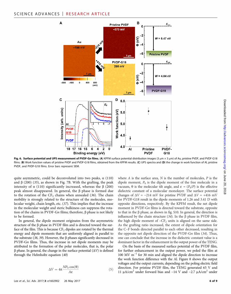
Finally, we further measured the surface potential difference of thepristine PVDF and PVDF-G18 to understand an important parameterthat can affect output performance (Fig. 6A) by the KPFM tools, com-pared to the Pt-coated Si tip. The surface potential values werecalculated as −156 mV for the Au film and −370 mV for the PVDFfilm, whereas PVDF-G18 showed a relatively higher potential value of+260 mV. Assuming that the surface potential of Al is not changedduring the full cycle, the measured surface potential values indicatethat the difference in work function between Al and PVDF-G18 is
Fig. 3. Mechanical bending, stability, and durability test of PVDF-Gn–based TENG. (A) Mechanical bending tests of the PVDF-based TENG. (B) Output current den-sities generated by pristine PVDF– and PVDF-G18–based TENGs before and after bending 3000 times. (C) Stability and durability test of the TENG under cycled com-pressive force of 50 N over 18,000 cycles.
4 of 9

SC I ENCE ADVANCES | R E S EARCH ART I C L E
on June 20, 2018http://advances.sciencem
ag.org/D
ownloaded from
smaller than that between Al and pristine PVDF, as shown in Fig. 6B. Thedecrease in work function with the grafting was supported by ultravioletphotoelectron spectroscopy (UPS) spectra, as shown in Fig. 6C. The workfunction can be determined from the difference between the incident lightenergy (hn = 21.22 eV) and the energy of the secondary cutoff (Ecutoff) asW = hn – (Ecutoff – EF). The onset of the secondary electron peak shiftedtoward a lower binding energy by 1.19 eV for pristine PVDF and 0.48 eVfor PVDF-G18, as compared with Al. On the basis of these results, thework function can be estimated to be approximately 5.55 (±0.19) eVand 4.84 (±0.16) eV in pristine PVDF and PVDF-G18, respectively(Fig. 6D), which agrees with the KPFM results. According to previous
Lee et al., Sci. Adv. 2017;3 : e1602902 26 May 2017
work, it is expected that the electron transfer from the Al to PVDF-G18is not effective; therefore, the output performance of the TENG should bedecreased because of the low electric potential generated between them.
The decrease of the work function in PVDF-G18 may be explainedin terms of microstructural change. The crystalline properties ofPVDF-based films were characterized by x-ray diffraction (XRD),compared with those of the PVDF film, and plotted in Fig. 7A.For the PVDF film, two representative peaks at 17.9° and 20.6° wereobserved. We thought that the two peaks would correspond to the(100) plane of the a phase and the (200) plane of the b phase, re-spectively. However, we found that the b (200) peak, which was
Fig. 4. Dielectric constant and loss tangent for PVDF-Gn films. Frequency dependence of (A) dielectric constant values and (B) loss tangent for PVDF-based filmswith various PtBA mole percents ranging from 0 to 18%.
Fig. 5. Relationship between the dielectric constant and output performance of PVDF-Gn–based TENG. (A) Measured output currents of the PVDF-based TENGwith the grafting ratio. (B) Saturated time and output current as a function of the PtBA mole percent ranging from 0 to 18%. Error bars represent SEM. (C) Calculatedcharging time of the capacitor increases from 2.3 to 4.52 s with the increase of the dielectric constant.
5 of 9
SC I ENCE ADVANCES | R E S EARCH ART I C L E
on June 20, 2018http://advances.sciencem
ag.org/D
ownloaded from
quite asymmetric, could be deconvoluted into two peaks, a (110)and b (200) (35), as shown in Fig. 7B. With the grafting, the peakintensity of a (110) significantly increased, whereas the b (200)peak almost disappeared. In general, the b phase is formed dueto the rotation of the CF2 chains when annealed (36). The chainmobility is strongly related to the structure of the molecules, mo-lecular weight, chain length, etc. (37). This implies that the increasein the molecular weight and steric bulkiness can suppress the rota-tion of the chains in PVDF-Gn films; therefore, b phase is not likelyto be formed.
In general, the dipole moment originates from the asymmetricstructure of the b phase in PVDF film and is directed toward the sur-face of the film. This is because CF2 dipoles are rotated by the thermalenergy and dipole moments that are uniformly aligned in parallel tothe substrate (38, 39). However, the b phases significantly decreased inPVDF-Gn films. Thus, the increase in net dipole moments may beattributed to the formation of the polar molecules, that is, the polarb phase. In general, the change in the surface potential (DV) is definedthrough the Helmholtz equation (40)
DV ¼ 4pNP0 cosðqÞ
Aeð5Þ
Lee et al., Sci. Adv. 2017;3 : e1602902 26 May 2017
where A is the surface area, N is the number of molecules, P is thedipole moment, P0 is the dipole moment of the free molecule in avacuum, q is the molecular tilt angle, and e = (P0/P) is the effectivedielectric constant of a molecular monolayer. The surface potentialchanges of DV = −214 mV for pristine PVDF and DV = +416 mVfor PVDF-G18 result in the dipole moments of 1.26 and 3.41 D withopposite directions, respectively. By the KPFM result, the net dipolemoment in PVDF-Gn films is directed toward the substrate, oppositeto that in the b phase, as shown in fig. S10. In general, the direction isinfluenced by the chain structure (34). In the b phase in PVDF film,the high dipole moment of –CF2 units is aligned on the same side.As the grafting ratio increased, the extent of dipole orientation forthe C–F bonds directed parallel to each other decreased, resulting inthe opposite net dipole direction of the PVDF-Gn film (34). Thus,one can conclude that the increase in the dielectric constant value is adominant factor in the enhancement in the output power of the TENG.
On the basis of the measured surface potential of the PVDF film,for further enhancement in the output power, we poled the film at100 MV m−1 for 30 min and aligned the dipole direction to increasethe work function difference with the Al. Figure 8 shows the outputvoltages and the output currents, depending on the poling electric fielddirection. For pristine PVDF film, the TENG generated 65 V and11 mA/cm2 under forward bias and −14 V and −2.7 mA/cm2 under
Fig. 6. Surface potential and UPS measurement of PVDF-Gn films. (A) KPFM surface potential distribution images (3 mm × 3 mm) of Au, pristine PVDF, and PVDF-G18films. (B) Work function values of pristine PVDF and PVDF-G18 films, obtained from the KPFM results. (C) UPS spectra and (D) the change in work function of Al, pristinePVDF, and PVDF-G18 films. Error bars represent SEM.
6 of 9

SC I ENCE ADVANCES | R E S EARCH ART I C L E
reverse bias. As the grafted PtBA reached 18%, the output voltage andcurrent density were measured to be 105 V and 25 mA/cm2 under for-ward bias and −39 V and −11 mA/cm2 under reverse bias. The signif-icant increase in the output power of PVDF-Gn results from thepositive charges on the surface of forward-polarized PVDF broughtinto contact with the aluminum, whereas the other side of its surfaceis covered by the back electrode.
Lee et al., Sci. Adv. 2017;3 : e1602902 26 May 2017
http://advaD
ownloaded from
CONCLUSIONIn summary, we reported a facile approach to enhance the outputpower of TENG with the successful synthesis of PtBA-grafted PVDFcopolymers for dielectric constant control. The copolymers wereprepared using the ATRP technique, and the PtBA was graftedup to 18%. In high-resolution XRD spectra, it was found that theb phases significantly decreased; thus, the copolymers were mainlycomposed of a phases with an enhanced dipole moment byp-bonding and polar characteristics of the ester functional groupsin the PtBA. As the grafting ratio increased to 18%, the dielectric con-stant values increased from 8.6 to 16.5 in the frequency range of 102
to 105 Hz, which we attributed to the increase of the net dipole mo-ment, supported by the KPFM measurements. This increase in thedielectric constant increased the density of the charges that could beaccumulated on the surface, generating output signals of 64.4 V and18.9 mA/cm2, twice the enhancement in both, compared to pristinePVDF–based nanogenerator. To prove this, we calculated the accumu-lated charges on the surface with different dielectric constant values,which showed an excellent correspondence with the measured outputcurrent values. The enhanced output performance is quite stable andreliable in harsh mechanical environments due to the high flexibilityof the films. Further increase in the output signals to 105 V and25 mA/cm2, a 20-fold enhancement in output power, was alsoachieved by poling the film to align the dipole direction, which im-proved the charge-accepting characteristics by increasing the workfunction of the copolymer. The enhanced output power resulted ina much faster charging property.
Fig. 7. XRD pattern of PVDF-Gn films. (A) High-resolution XRD patterns of pris-tine PVDF and PVDF-Gn films as a function of PtBA mole percent. (B) Expandedview of the second peak in (A). The peak can be deconvoluted into two peaks,a (110) (red) and b (200) (blue) phases.
on June 20, 2018nces.sciencem
ag.org/
Fig. 8. Output performance depending on the poling electric field direction. Output voltages and current densities for (A) pristine PVDF–based and (B) PVDF-G18–based TENGs under different poling electric field directions. (C) Circuit diagrams and different performances among TENGs fabricated under different poling electricfield directions.
7 of 9
SC I ENCE ADVANCES | R E S EARCH ART I C L E
on June 20, 2018http://advances.sciencem
ag.org/D
ownloaded from
MATERIALS AND METHODSMaterials and instrumentsPVDF [KF1100; Mn = 168.8 kDa, polydispersity index (PDI) = 2.94]was purchased from Kureha. tert-Butyl acrylate (tBA) was purchasedfrom Sigma-Aldrich and was passed through an aluminum oxide col-umn to remove the inhibitor before use. Copper(I) chloride (CuCl,99.999%) and 1,1,4,7,10,10-hexamethyltriethylenetetramine (HMTETA)were purchased from Alfa Aesar. 1-Methyl-2-pyrrolidone (NMP)was purchased from JUNSEI. All solvents were reagent grade, andall reagents were used as received. The molecular mass of PVDFand graft copolymers were measured by gel permeation chromatog-raphy (GPC) conducted at 23°C in N,N′-dimethylformamide (DMF)at a flow rate of 1 ml/min, using an Agilent 1260 Infinity GPC systemequipped with a PLgel 5 mmMixed B column (Polymer Laboratories)and differential refractive index detectors. Monodisperse PS standard(Polymer Laboratories) was used for calibration. 1H NMR wasperformed in deuterated DMF, using a 400-MR DD2 (Agilent)400-MHz spectrometer. The FTIR spectra were recorded on a 670-IR(Agilent) spectrophotometer.
Synthesis of PVDF-Gn graft copolymersPVDF (3.0 g) was dissolved in NMP (30 ml) at 60°C. Once the PVDFhad completely dissolved in NMP, tBA (18.02 g, 93.5 mmol), CuCl(0.03 g, 0.202 mmol), and HMTETA (0.127 g, 0.367 mmol) wereadded to the PVDF solution at room temperature under an argon at-mosphere. The reaction mixture was then heated at 120°C for a cer-tain reaction time (either 12, 24, or 72 hours). After cooling to roomtemperature, the copolymer solution was poured into water/methanol(1:4, v/v) and filtered off. The precipitated copolymer was stirredovernight in a large volume of hexane. The copolymer was then re-covered by filtration, redissolved in NMP, and precipitated into water/methanol (1:4, v/v). Last, the graft copolymers were dried under a vac-uum. For 1H NMR (400 MHz, C3D7NO), d (ppm) values were asfollows: 2.9 to 3.2 (br, 2H, −CF2–CH2–CF2–CH2–), 2.3 to 2.5 (br,2H, −CF2–CH2–CH2–CF2–), and 1.4 to 1.65 [br, 9H, −C(CH3)3].For PVDF-G10, the parameters used were as follows: Mn = 180.0 kDa,PDI = 1.58; for PVDF-G15, Mn = 201.8 kDa, PDI = 1.56; and forPVDF-G18, Mn = 218.5 kDa, PDI = 1.47.
Production of PVDF-based TENGIn the experiment, the synthesized PVDF-Gn solution was first castinto a film shape in a blocking layer on an SiO2/Si substrate anddried in the atmosphere at 60°C for 10 min to remove the DMF so-lution. This layer was then maintained at 90°C for 5 hours andcooled at room temperature. After the PVDF-Gn film layer waspeeled off from the substrate, the PVDF-Gn film of 30 mm was ob-tained. To fabricate the TENG, a Kapton film was glued between Alfoil and PVDF-Gn film, followed by the attachment of Al electrodeon the opposite side of the Kapton film, which acts as the top layer.The spacer between the bottom electrode and the PVDF-Gn filmwas made of four springs with a length of 5 mm in each corner. Last,PVDF-Gn–based TENGs were obtained. The effective area and gapdistance of both PVDF and PVDF-Gn films were 2 cm × 2 cm and1 mm, respectively.
Characterization and measurementsThe morphologies of PVDF-based films were further characterized bya field emission SEM. The dielectric constants of the PVDF-basedfilms were measured by an impedance analyzer (Agilent) over the fre-
Lee et al., Sci. Adv. 2017;3 : e1602902 26 May 2017
quency range of 102 to 106 Hz at room temperature. A pushing tester(model no. ET-126-4, Labworks Inc.) was used to create vertical com-pressive strain in the TENG. A Tektronix DPO 3052 digital phosphoroscilloscope and a low-noise current preamplifier (model no. SR570,Stanford Research Systems Inc.) were used for electrical measure-ments. Nanoindentation tests were carried out at a constant inden-tation strain rate of 0.05 s−1, with a maximum indentation depth of20 mm, with a Berkovich indenter, using the DCM II module inNanoindenter G200 (Agilent). The KPFM measurements werecarried out using Park Systems XE-100 with Pt/Cr-coated silicontips (tip radius, 25 nm; force constant, 3 N m−1; and resonance fre-quency, 75 kHz). KPFM images (3 mm × 3 mm) were scanned at ascanning speed of 0.5 Hz in the noncontact mode with a 2-Vac sig-nal with a frequency of 17 kHz. UPS (ESCALAB 250Xi, ThermoFisher) was performed using the He I (hv = 21.2 eV) photon lineof a He discharge lamp under ultrahigh vacuum conditions formeasurement of the work function.
SUPPLEMENTARY MATERIALSSupplementary material for this article is available at http://advances.sciencemag.org/cgi/content/full/3/5/e1602902/DC1fig. S1. Output voltages of PVDF-based TENGs.fig. S2. Output performances of different polymer-based TENGs.fig. S3. Output performance of pristine PVDF–based TENG with the resistance of external loads.fig. S4. Average current density and charge density.fig. S5. Calculated electrostatic potentials.fig. S6. Capacitor charging properties of pristine PVDF–based TENGs.fig. S7. AFM and SEM images of the PVDF-Gn films.fig. S8. Nanoindentation test for the PVDF-Gn films.fig. S9. Dielectric constant of PVDF-Gn films according to PtBA mole percents.fig. S10. Structures of PVDF and PVDF-Gn.
REFERENCES AND NOTES1. W. J. Sarjeant, J. Zirnheld, F. W. MacDougall, Capacitors. IEEE Trans. Plasma Sci. 26,
1368–1392 (1998).2. Y. Cao, P. C. Irwin, K. Younsi, The future of nanodielectrics in the electrical power industry.
IEEE Trans. Dielectr. Electr. Insul. 11, 797–807 (2004).3. S. Ducharme, An inside-out approach to storing electrostatic energy. ACS Nano 3,
2447–2450 (2009).4. B. Chu, X. Zhou, K. Ren, B. Neese, M. Lin, Q. Wang, F. Bauer, Q. M. Zhang, A dielectric
polymer with high electric energy density and fast discharge speed. Science 313,334–336 (2006).
5. S. Wu, W. Li, M. Lin, Q. Burlingame, Q. Chen, A. Payzant, K. Xiao, Q. M. Zhang, Aromaticpolythiourea dielectrics with ultrahigh breakdown field strength, low dielectric loss, andhigh electric energy density. Adv. Mater. 25, 1734–1738 (2013).
6. Q. Chen, Y. Shen, S. Zhang, Q. M. Zhang, Polymer-based dielectrics with high energystorage density. Annu. Rev. Mater. Res. 45, 433–458 (2015).
7. M.-H. Yoon, H. Yan, A. Facchetti, T. J. Marks, Low-voltage organic field-effect transistorsand inverters enabled by ultrathin cross-linked polymers as gate dielectrics. J. Am.Chem. Soc. 127, 10388–10395 (2005).
8. M. E. Roberts, N. Queraltó, S. C. B. Mannsfeld, B. N. Reinecke, W. Knoll, Z. Bao, Cross-linkedpolymer gate dielectric films for low-voltage organic transistors. Chem. Mater. 21,2292–2299 (2009).
9. M. T. Dang, L. Hirsch, G. Wantz, P3HT:PCBM, best seller in polymer photovoltaic research.Adv. Mater. 23, 3597–3602 (2011).
10. L. Huo, S. Zhang, X. Guo, F. Xu, Y. Li, J. Hou, Replacing alkoxy groups with alkylthienylgroups: A feasible approach to improve the properties of photovoltaic polymers.Angew. Chem. 123, 9871–9876 (2011).
11. S. Dadbin, M. Frounchi, M. H. Saeid, F. Gangi, Molecular structure and physical propertiesof E-beam crosslinked low-density polyethylene for wire and cable insulationapplications. J. Appl. Polym. Sci. 86, 1959–1969 (2002).
12. Z. Li, J. Chen, J. Yang, Y. Su, X. Fan, Y. Wu, C. Yu, Z. L. Wang, b-Cyclodextrin enhancedtriboelectrification for self-powered phenol detection and electrochemical degradation.Energy Environ. Sci. 8, 887–896 (2015).
13. J.-H. Kim, J. Chun, J. W. Kim, W. J. Choi, J. M. Baik, Self-powered, room-temperatureelectronic nose based on triboelectrification and heterogeneous catalytic reaction.Adv. Funct. Mater. 25, 7049–7055 (2015).
8 of 9

SC I ENCE ADVANCES | R E S EARCH ART I C L E
on June 20, 2018http://advances.sciencem
ag.org/D
ownloaded from
14. S. Wang, L. Lin, Z. L. Wang, Nanoscale triboelectric-effect-enabled energy conversion forsustainably powering portable electronics. Nano Lett. 12, 6339–6346 (2012).
15. Y. Yang, H. Zhang, Y. Liu, Z.-H. Lin, S. Lee, Z. Lin, C. P. Wong, Z. L. Wang, Silicon-basedhybrid energy cell for self-powered electrodegradation and personal electronics.ACS Nano 7, 2808–2813 (2013).
16. J. Chun, J. W. Kim, W.-s. Jung, C.-Y. Kang, S.-W. Kim, Z. L. Wang, J. M. Baik, Mesoporouspores impregnated with Au nanoparticles as effective dielectrics for enhancingtriboelectric nanogenerator performance in harsh environments. Energy Environ. Sci. 8,3006–3012 (2015).
17. J. Chen, H. Guo, X. He, G. Liu, Y. Xi, H. Shi, C. Hu, Enhancing performance of triboelectricnanogenerator by filling high dielectric nanoparticles into sponge PDMS film.ACS Appl. Mater. Interfaces 8, 736–744 (2016).
18. G. Zhu, Z.-H. Lin, Q. Jing, P. Bai, C. Pan, Y. Yang, Y. Zhou, Z. L. Wang, Toward large-scaleenergy harvesting by a nanoparticle-enhanced triboelectric nanogenerator.Nano Lett. 13, 847–853 (2013).
19. G. Zhu, C. Pan, W. Gu, C.-Y. Chen, Y. Zhou, R. Yu, Z. L. Wang, Triboelectric-generator-drivenpulse electrodeposition for micropatterning. Nano Lett. 12, 4960–4965 (2012).
20. Z. Zhao, X. Pu, C. Du, L. Li, C. Jiang, W. Hu, Z. L. Wang, Freestanding flag-type triboelectricnanogenerator for harvesting high-altitude wind energy from arbitrary directions.ACS Nano 10, 1780–1787 (2016).
21. P. Bai, G. Zhu, Y. S. Zhou, S. Wang, J. Ma, G. Zhang, Z. L. Wang, Dipole-moment-inducedeffect on contact electrification for triboelectric nanogenerators. Nano Res. 7, 990–997(2014).
22. P. Bai, G. Zhu, Z.-H. Lin, Q. Jing, J. Chen, G. Zhang, J. Ma, Z. L. Wang, Integratedmultilayered triboelectric nanogenerator for harvesting biomechanical energy fromhuman motions. ACS Nano 7, 3713–3719 (2013).
23. Y. S. Zhou, S. Wang, Y. Yang, G. Zhu, S. Niu, Z.-H. Lin, Y. Liu, Z. L. Wang, Manipulatingnanoscale contact electrification by an applied electric field. Nano Lett. 14, 1567–1572(2014).
24. K. Y. Lee, J. Chun, J.-H. Lee, K. N. Kim, N.-R. Kang, J.-Y. Kim, M. H. Kim, K.-S. Shin,M. K. Gupta, J. M. Baik, S.-W. Kim, Hydrophobic sponge structure-based triboelectricnanogenerator. Adv. Mater. 26, 5037–5042 (2014).
25. A. V. Shirinov, W. K. Schomburg, Pressure sensor from a PVDF film. Sens. Actuators A Phys.142, 48–55 (2008).
26. Y. Song, Y. Shen, H. Liu, Y. Lin, M. Li, C.-W. Nan, Enhanced dielectric and ferroelectricproperties induced by dopamine-modified BaTiO3 nanofibers in flexible poly(vinylidenefluoride-trifluoroethylene) nanocomposites. J. Mater. Chem. 22, 8063–8068 (2012).
27. M. Li, H. J. Wondergem, M.-J. Spijkman, K. Asadi, I. Katsouras, P. W. M. Blom,D. M. de Leeuw, Revisiting the d-phase of poly(vinylidene fluoride) for solution-processedferroelectric thin Films. Nat. Mater. 12, 433–438 (2013).
28. E. Fernández, C. Mijangos, J.-M. Guenet, M. T. Cuberes, D. López, New hydrogels based onthe interpenetration of physical gels of agarose and chemical gels of polyacrylamide.Eur. Polym. J. 45, 932–939 (2009).
29. F. Guan, L. Yang, J. Wang, B. Guan, K. Han, Q. Wang, L. Zhu, Confined ferroelectricproperties in poly(vinylidene fluoride-co-chlorotrifluoroethylene)-graft-polystyrene graftcopolymers for electric energy storage applications. Adv. Funct. Mater. 21, 3176–3188(2011).
30. Z.-H. Lin, G. Cheng, Y. Yang, Y. S. Zhou, S. Lee, Z. L. Wang, Triboelectric nanogenerator asan active UV photodetector. Adv. Funct. Mater. 24, 2810–2816 (2014).
Lee et al., Sci. Adv. 2017;3 : e1602902 26 May 2017
31. F.-R. Fan, L. Lin, G. Zhu, W. Wu, R. Zhang, Z. L. Wang, Transparent triboelectricnanogenerators and self-powered pressure sensors based on micropatterned plasticfilms. Nano Lett. 12, 3109–3114 (2012).
32. Z.-M. Dang, Y.-H. Lin, C.-W. Nan, Novel ferroelectric polymer composites with highdielectric constants. Adv. Mater. 15, 1625–1629 (2003).
33. B. Luo, X. Wang, Y. Wang, L. Li, Fabrication, characterization, properties and theoreticalanalysis of ceramic/PVDF composite flexible films with high dielectric constant and lowdielectric loss. J. Mater. Chem. A 2, 510–519 (2014).
34. Z. Ahmad, Polymer dielectric materials, in Dielectric Material, M. A. Silaghi, Ed. (Intech,2012), pp. 3–26.
35. H. Yu, T. Huang, M. Lu, M. Mao, Q. Zhang, H. Wang, Enhanced power output of anelectrospun PVDF/MWCNTs-based nanogenerator by tuning its conductivity.Nanotechnology 24, 405401 (2013).
36. R. Gregorio Jr., M. Cestari, Effect of crystallization temperature on the crystalline phasecontent and morphology of poly(vinylidene fluoride). J. Polym. Sci. B Polym. Phys. 32,859–870 (1994).
37. L. Xu, V. Selin, A. Zhuk, J. F. Ankner, S. A. Sukhishvili, Molecular weight dependence ofpolymer chain mobility within multilayer films. ACS Macro Lett. 2, 865–868 (2013).
38. Z. Hu, M. Tian, B. Nysten, A. M. Jonas, Regular arrays of highly ordered ferroelectricpolymer nanostructures for non-volatile low-voltage memories. Nat. Mater. 8,62–67 (2009).
39. S. Satapathy, S. Pawar, P. K. Gupta, K. B. R. Varma, Effect of annealing on phase transitionin poly(vinylidene fluoride) films prepared using polar solvent. Bull. Mater. Sci. 34,727–733 (2011).
40. A. Henning, G. Günzburger, R. Jöhr, Y. Rosenwaks, B. Bozic-Weber, C. Housecroft,E. C. Constable, E. Meyer, T. Glatzel, Kelvin probe force microscopy of nanocrystalline TiO2
photoelectrodes. Beilstein J. Nanotechnol. 4, 418–428 (2013).
AcknowledgmentsFunding: This work was supported by the Samsung Research Funding Center of SamsungElectronics under project number SRFC-TA1403-06. Author contributions: J.W.L., H.J.C., andJ.C. conceived the idea, analyzed the data, and wrote the manuscript. K.N.K. and S.K.conducted output measurements and prepared the figures. C.W.A., I.W.K., J.-Y.K., andS.-W.K. provided advice for the research and revised the manuscript. C.Y. and J.M.B. conceivedand supervised this study and provided intellectual and technical guidance. All authorsdiscussed the results and wrote and commented on the manuscript. Competing interests:The authors declare that they have no competing interests. Data and materials availability:All data needed to evaluate the conclusions in the paper are present in the paper and/orthe Supplementary Materials. Additional data related to this paper may be requested fromthe authors.
Submitted 20 November 2016Accepted 28 March 2017Published 26 May 201710.1126/sciadv.1602902
Citation: J. W. Lee, H. J. Cho, J. Chun, K. N. Kim, S. Kim, C. W. Ahn, I. W. Kim, J.-Y. Kim, S.-W. Kim,C. Yang, J. M. Baik, Robust nanogenerators based on graft copolymers via control of dielectricsfor remarkable output power enhancement. Sci. Adv. 3, e1602902 (2017).
9 of 9

output power enhancementRobust nanogenerators based on graft copolymers via control of dielectrics for remarkable
Sang-Woo Kim, Changduk Yang and Jeong Min BaikJae Won Lee, Hye Jin Cho, Jinsung Chun, Kyeong Nam Kim, Seongsu Kim, Chang Won Ahn, Ill Won Kim, Ju-Young Kim,
DOI: 10.1126/sciadv.1602902 (5), e1602902.3Sci Adv
ARTICLE TOOLS http://advances.sciencemag.org/content/3/5/e1602902
MATERIALSSUPPLEMENTARY http://advances.sciencemag.org/content/suppl/2017/05/22/3.5.e1602902.DC1
REFERENCES
http://advances.sciencemag.org/content/3/5/e1602902#BIBLThis article cites 39 articles, 1 of which you can access for free
PERMISSIONS http://www.sciencemag.org/help/reprints-and-permissions
Terms of ServiceUse of this article is subject to the
registered trademark of AAAS.is aScience Advances Association for the Advancement of Science. No claim to original U.S. Government Works. The title
York Avenue NW, Washington, DC 20005. 2017 © The Authors, some rights reserved; exclusive licensee American (ISSN 2375-2548) is published by the American Association for the Advancement of Science, 1200 NewScience Advances
on June 20, 2018http://advances.sciencem
ag.org/D
ownloaded from


![arXiv:1703.09528v3 [stat.ML] 4 Jul 2018Anh Tong and Jaesik Choi Ulsan National Institute of Science and Technology 50 UNIST-gil, Ulsan, South Korea, 44919 Abstract Analyzing time series](https://static.fdocuments.in/doc/165x107/5f1f3fd4a6f308609546ca02/arxiv170309528v3-statml-4-jul-2018-anh-tong-and-jaesik-choi-ulsan-national.jpg)