
Applied Hyd Trbns
92
PRESENTED BY Dr. S.SUYAMBAZHAHAN PRINCIPAL S.A.ENGINEERING COLLEGE CHENNAI - 600078
-
Upload
kadaikodi-paamaran -
Category
Documents
-
view
220 -
download
0
description
applied
Transcript of Applied Hyd Trbns
PRESENTED BY
Dr. S.SUYAMBAZHAHAN PRINCIPAL
S.A.ENGINEERING COLLEGECHENNAI - 600078
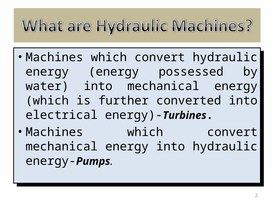
• Machines which convert hydraulic energy (energy possessed by water) into mechanical energy (which is further converted into electrical energy)-Turbines.
• Machines which convert mechanical energy into hydraulic energy-Pumps.
• Machines which convert hydraulic energy (energy possessed by water) into mechanical energy (which is further converted into electrical energy)-Turbines.
• Machines which convert mechanical energy into hydraulic energy-Pumps.
2
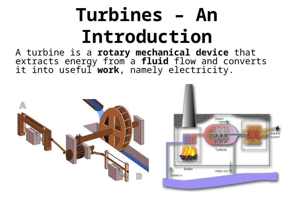
Turbines – An IntroductionA turbine is a rotary mechanical device that extracts energy from a fluid flow and converts it into useful work, namely electricity.

Hydraulic Turbines convert Hydraulic Energy possessed by water into Mechanical Energy which is further converted into Electrical Energy by Generator. This energy obtained is know as hydro-electric power which is one of the cheapest form of energy generation.
Hydraulic Turbines convert Hydraulic Energy possessed by water into Mechanical Energy which is further converted into Electrical Energy by Generator. This energy obtained is know as hydro-electric power which is one of the cheapest form of energy generation.
4
5
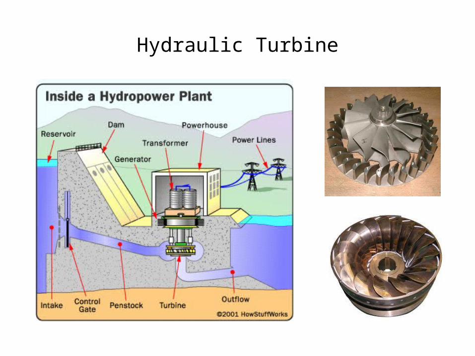
Hydraulic Turbine
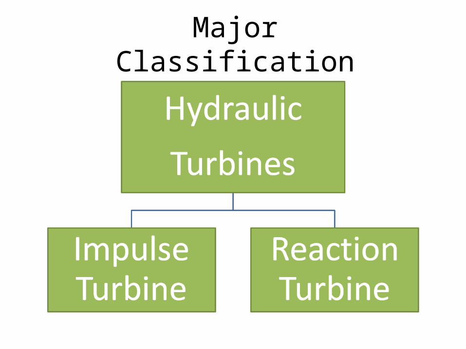
Major Classification
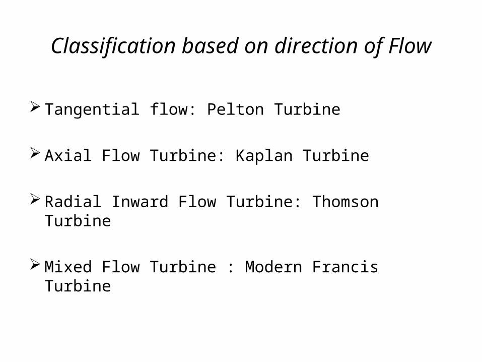
Classification based on direction of Flow
Tangential flow: Pelton Turbine
Axial Flow Turbine: Kaplan Turbine
Radial Inward Flow Turbine: Thomson Turbine
Mixed Flow Turbine : Modern Francis Turbine
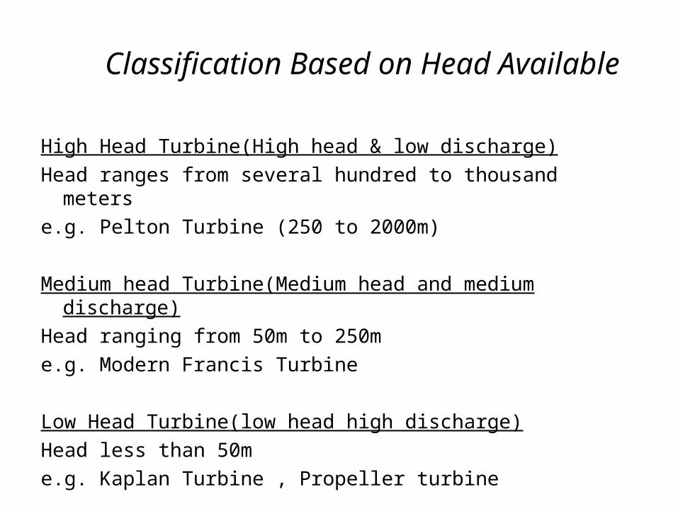
Classification Based on Head Available
High Head Turbine(High head & low discharge)Head ranges from several hundred to thousand meterse.g. Pelton Turbine (250 to 2000m)
Medium head Turbine(Medium head and medium discharge)Head ranging from 50m to 250me.g. Modern Francis Turbine
Low Head Turbine(low head high discharge)Head less than 50me.g. Kaplan Turbine , Propeller turbine
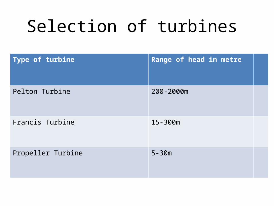
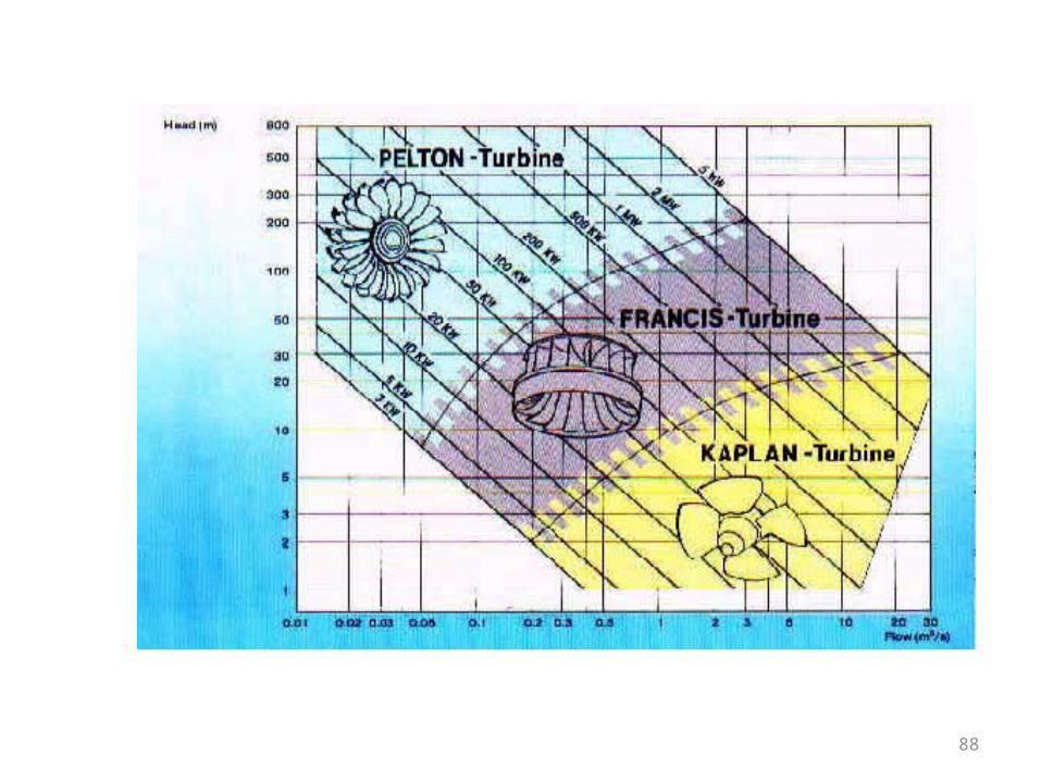
Selection of turbines
Type of turbine Range of head in metre
Pelton Turbine 200-2000m
Francis Turbine 15-300m
Propeller Turbine 5-30m
Reaction Turbine Reaction turbines are acted on by water, which changes
pressure as it moves through the turbine and gives up its energy.
They must be encased to contain the water pressure (or suction), or they must be fully submerged in the water flow.
Most water turbines in use are reaction turbines and are used in low (<30m/98 ft) and medium (30-300m/98–984 ft) head applications. In reaction turbine pressure drop occurs in both fixed and moving blades. It is largely used in dam and large power plants.
E.g. Francis Turbine, Kaplan Turbine.
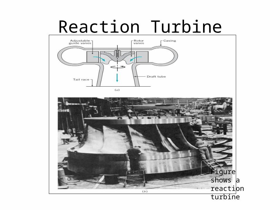
Reaction Turbine
Figure shows a reaction turbine
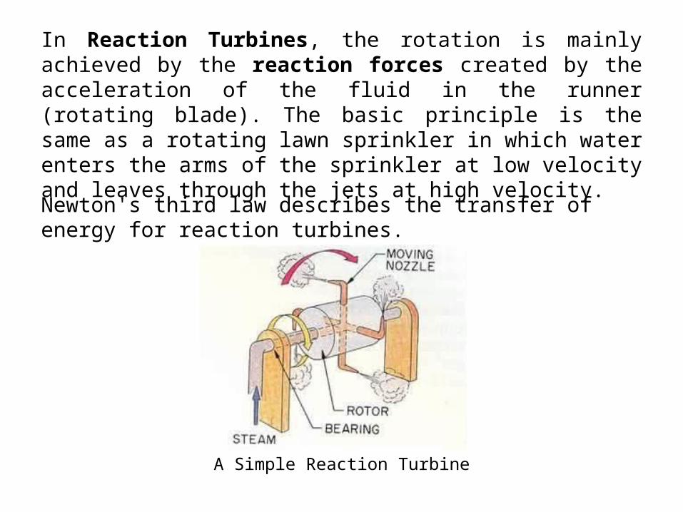
In Reaction Turbines, the rotation is mainly achieved by the reaction forces created by the acceleration of the fluid in the runner (rotating blade). The basic principle is the same as a rotating lawn sprinkler in which water enters the arms of the sprinkler at low velocity and leaves through the jets at high velocity.
Newton's third law describes the transfer of energy for reaction turbines.
A Simple Reaction Turbine
Reaction Turbine
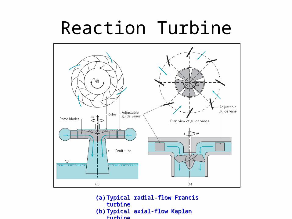
(a)(a) Typical radial-flow Francis turbineTypical radial-flow Francis turbine(b)(b) Typical axial-flow Kaplan turbine.Typical axial-flow Kaplan turbine.
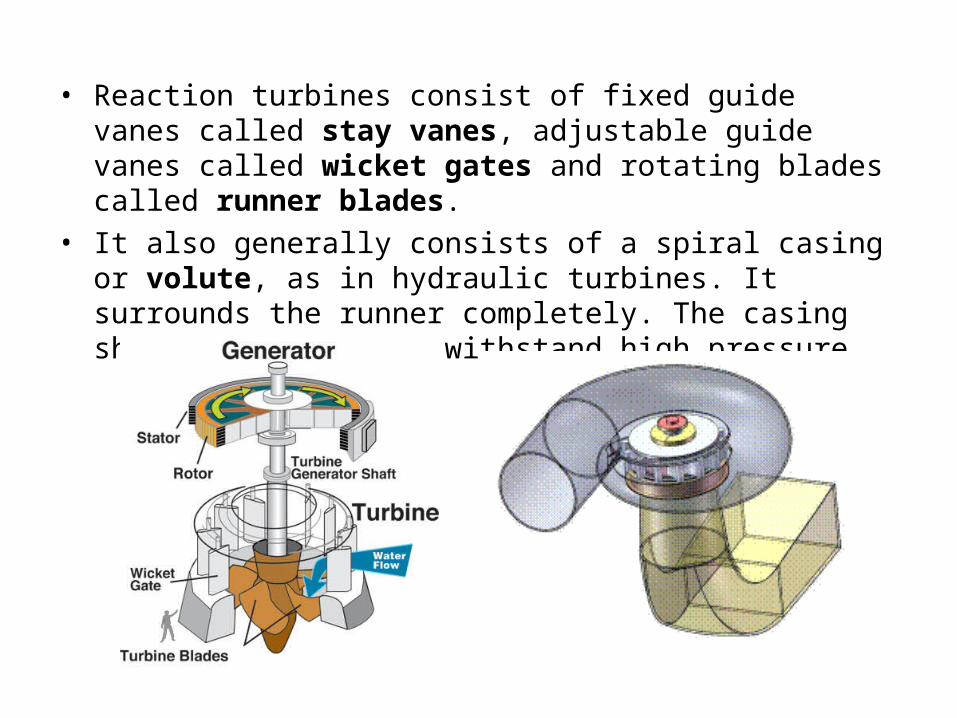
• Reaction turbines consist of fixed guide vanes called stay vanes, adjustable guide vanes called wicket gates and rotating blades called runner blades.
• It also generally consists of a spiral casing or volute, as in hydraulic turbines. It surrounds the runner completely. The casing should be strong to withstand high pressure.
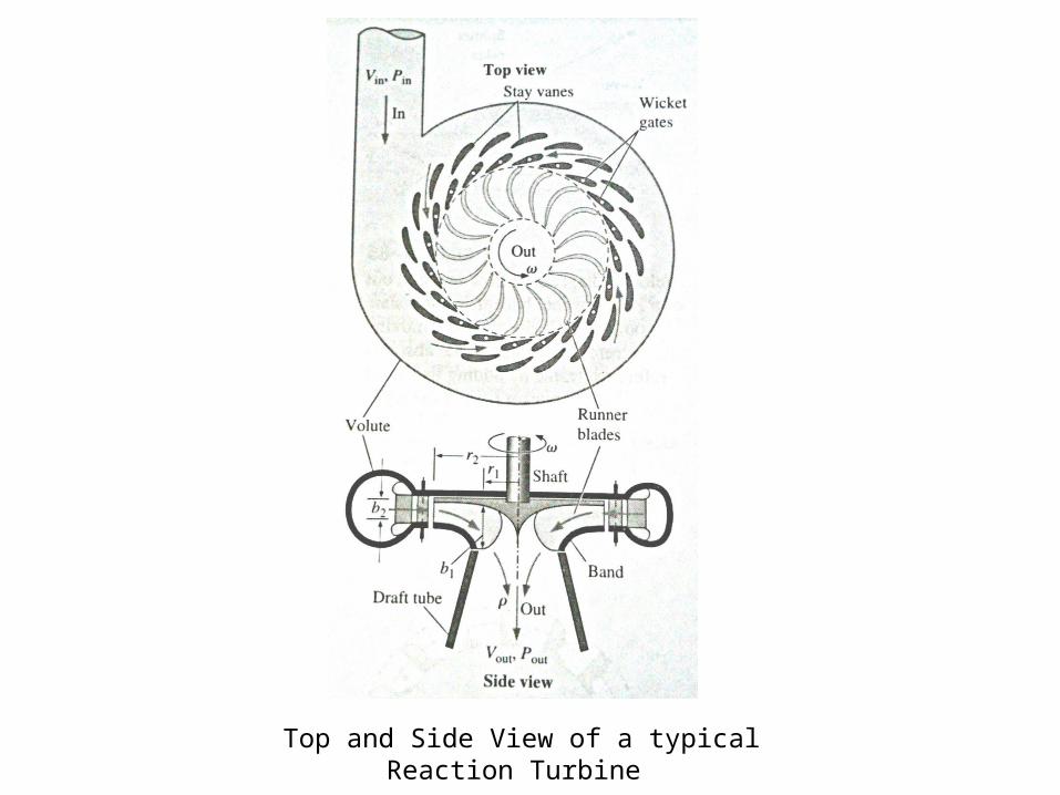
Top and Side View of a typical Reaction Turbine
• Fluid enters tangentially at high pressure, is turned toward the runner by the stay vanes as it moves along the volute, and then passes through the wicket gates with a large tangential velocity component.
• Momentum is exchanged between the fluid and the runner, and the runner rotates.
• Unlike impulse turbine, the water completely fills the casing of a reaction turbine.
• Reaction turbine generally produces more power than an impulse turbine.
• Wicket gates control volume flow rate.
Highlights of Reaction Turbine
There is both a pressure drop and a fluid relative speed change across the rotor.
Guide vanes act as nozzle to accelerate the flow and turn it in the appropriate direction as the fluid enters the rotor.
Part of the pressure drop occurs across the guide vanes and part occurs across the rotor.
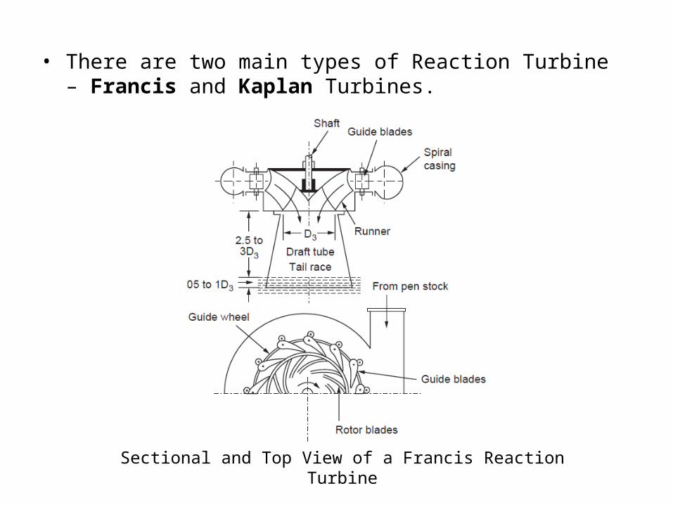
• There are two main types of Reaction Turbine – Francis and Kaplan Turbines.
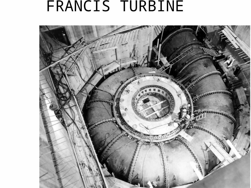
Sectional and Top View of a Francis Reaction Turbine
• Francis Turbine is the first hydraulic turbine with radial inflow. It was designed by an American scientist James Francis.
• If the water flows radially through the runner , from outwards to inwards then it is known as an inward radial flow turbine.
• Francis turbine is a reaction turbine as the energy available at the inlet of the turbine is a combination of kinetic and pressure energy.
20
• CASING: The runner is completely enclosed in an air-tight spiral casing. The casing and runner are always full of water.
• GUIDE MECHANISM: It consists of a stationary circular wheel on which stationary guide vanes are fixed. The guide vanes allow the water to strike the vanes of the runner without shock at inlet
• RUNNER: It is a circular wheel on which a series of curved radial guide vanes are fixed.
• DRAFT TUBE: It is used for discharging water from the outlet of the runner to the tail race.
21

FRANCIS TURBINE
FRANCIS TURBINE

RUNNER
GUIDE WHEEL
MOVABLE VANES
STATIONARY GUIDE VANES
24
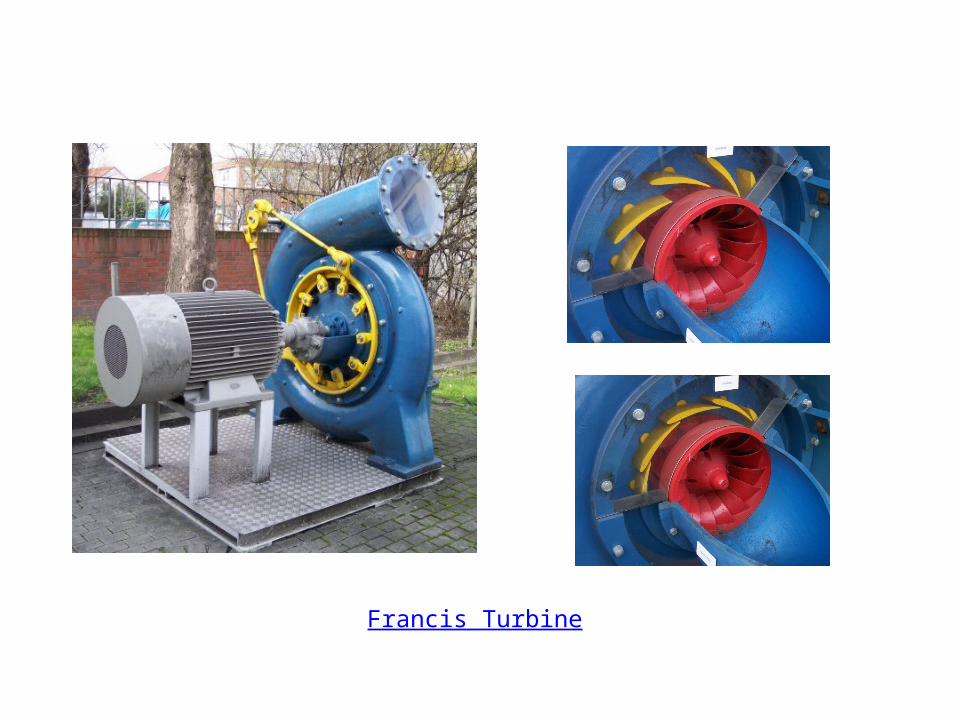
Francis Turbine
• Kaplan turbine is an axial flow reaction turbine. The water flows through the runner of the turbine in an axial direction and the energy at the inlet of the turbine is the sum of kinetic and pressure energy .
• In an axial flow reaction turbine the shaft is vertical. The lower end of the shaft is larger and is known as ‘hub’ or ‘boss’. It is on this hub that the vanes are attached. If the vanes are adjustable then it is known as kaplan Turbine and if the vanes are non adjustable then it is known as Propeller Turbine.
26
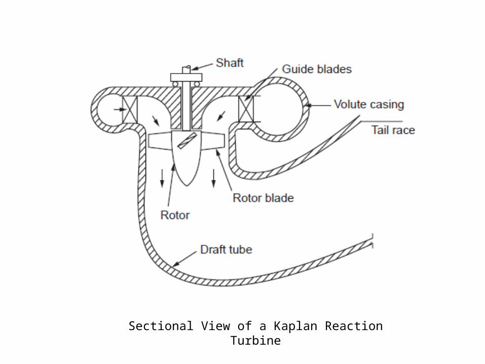
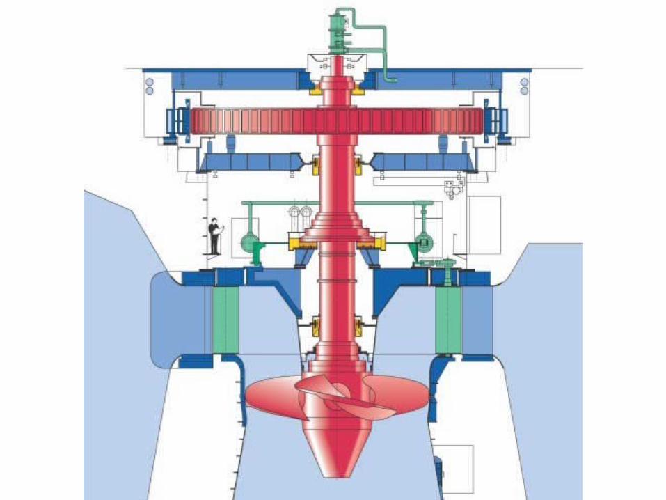
Sectional View of a Kaplan Reaction Turbine

KAPLAN TURBINE
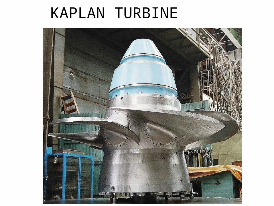
KAPLAN TURBINE
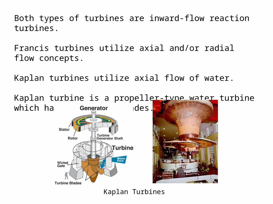
Both types of turbines are inward-flow reaction turbines.
Francis turbines utilize axial and/or radial flow concepts.
Kaplan turbines utilize axial flow of water.
Kaplan turbine is a propeller-type water turbine which has adjustable blades.
Kaplan Turbines
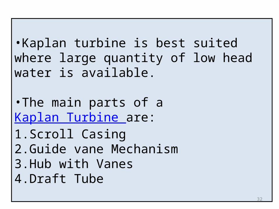
•Kaplan turbine is best suited where large quantity of low head water is available.
•The main parts of a Kaplan Turbine are:1.Scroll Casing2.Guide vane Mechanism3.Hub with Vanes4.Draft Tube
32
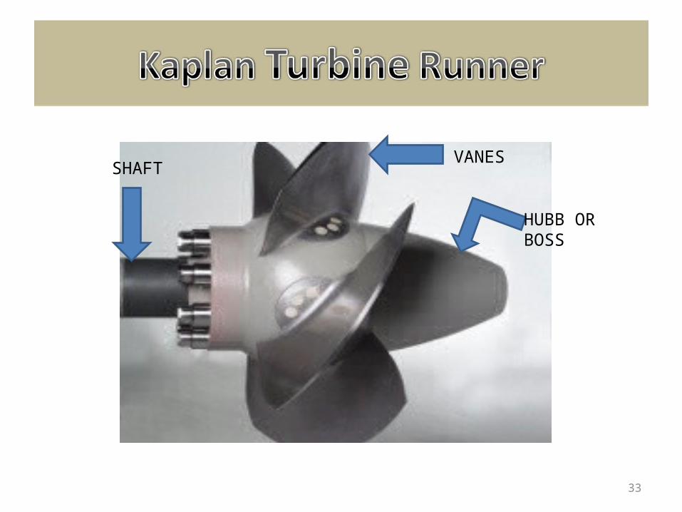
HUBB OR BOSS
VANESSHAFT
33
• The water enters the turbine through the guide vanes which are aligned such as to give the flow a suitable degree of swirl.
• The flow from guide vanes pass through the curved passage which forces the radial flow to axial direction.
• The axial flow of water with a component of swirl applies force on the blades of the rotor and looses its momentum, both linear and angular, producing torque and rotation (their product is power) in the shaft.
• The scheme for production of hydroelectricity by Kaplan Turbine is same as that for Francis Turbine.
34
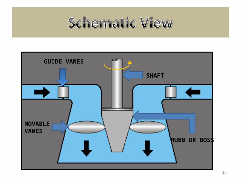
GUIDE VANES
MOVABLEVANES
SHAFT
HUBB OR BOSS
35
Impulse Turbine Impulse turbines change the velocity of a water jet. The jet
pushes on the turbine's curved blades which changes the direction of the flow. The resulting change in momentum (impulse) causes a force on the turbine blades.
Since the turbine is spinning, the force acts through a distance (work) and the diverted water flow is left with diminished energy.
An impulse turbine is one which the pressure of the fluid flowing over the rotor blades is constant and all the work output is due to the change in kinetic energy of the fluid.
E.g. Pelton Wheel
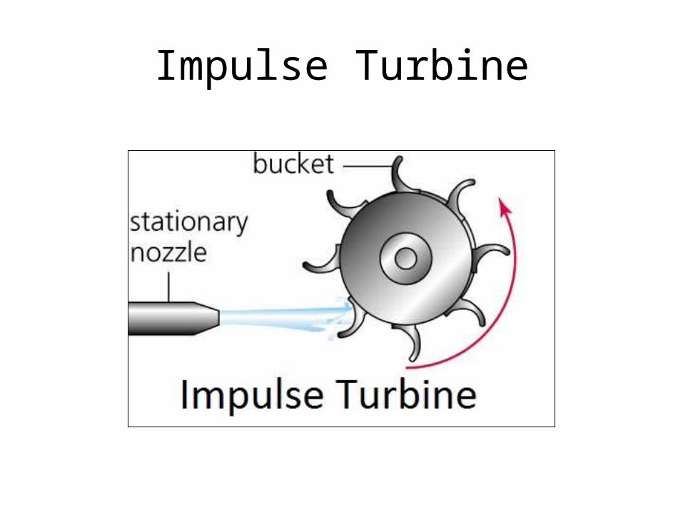
Impulse Turbine
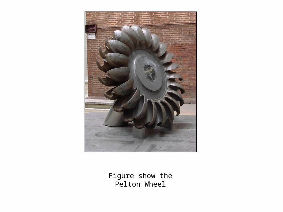
Figure show the Pelton Wheel
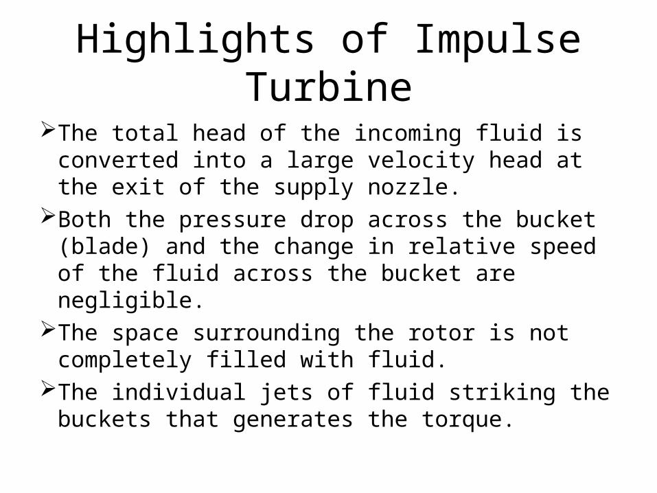
Highlights of Impulse Turbine
The total head of the incoming fluid is converted into a large velocity head at the exit of the supply nozzle.
Both the pressure drop across the bucket (blade) and the change in relative speed of the fluid across the bucket are negligible.
The space surrounding the rotor is not completely filled with fluid.
The individual jets of fluid striking the buckets that generates the torque.
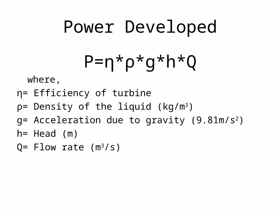
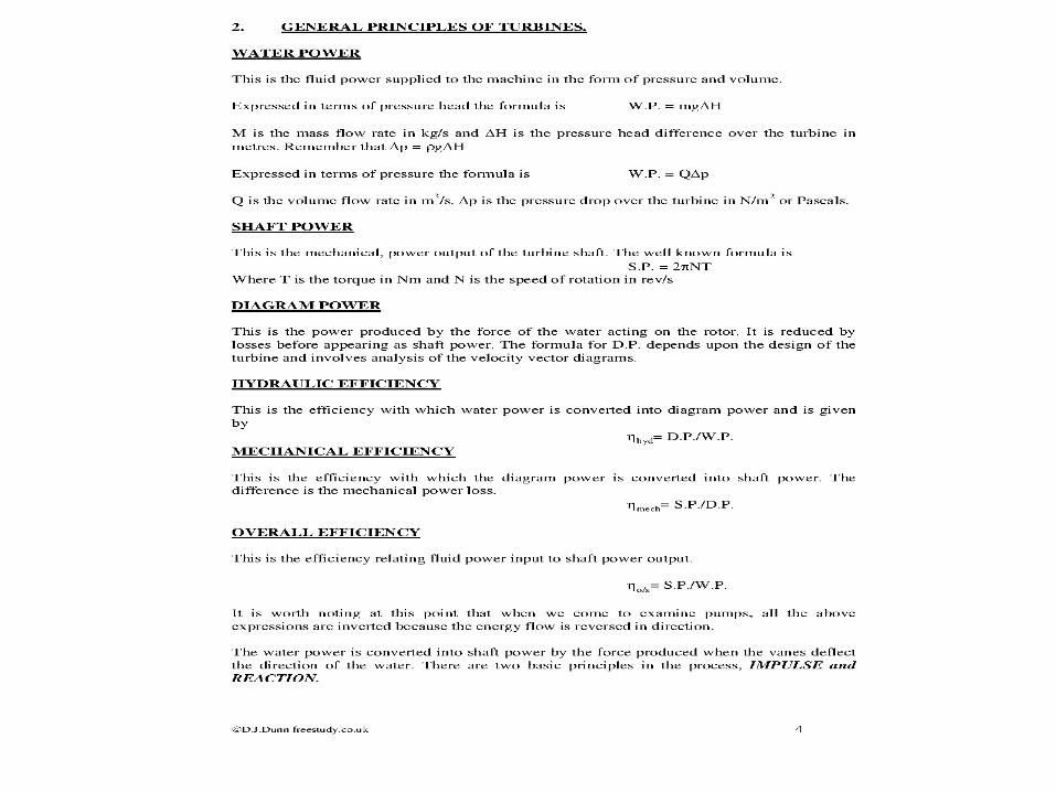
Power Developed
P=η*ρ*g*h*Qwhere,
η= Efficiency of turbineρ= Density of the liquid (kg/m3)g= Acceleration due to gravity (9.81m/s2)h= Head (m)Q= Flow rate (m3/s)

SPLITTER
BUCKETS OR VANES
RUNNER 41
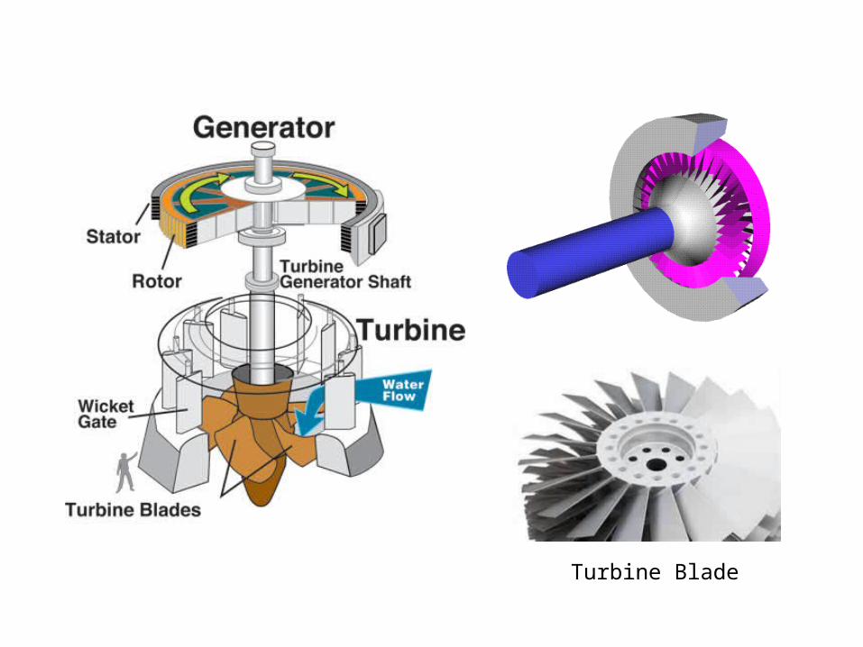
Turbine Blade
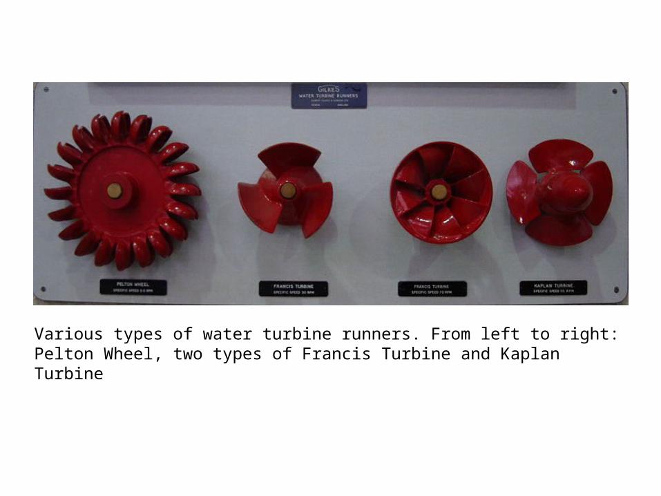
Various types of water turbine runners. From left to right: Pelton Wheel, two types of Francis Turbine and Kaplan Turbine

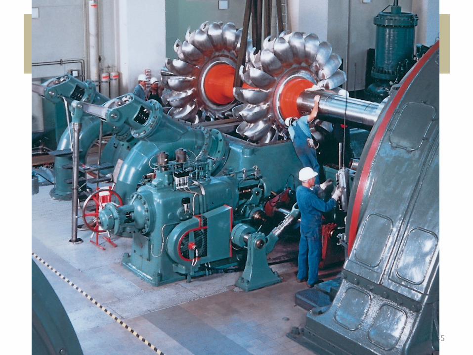
A Francis turbine runner, rated at nearly one million hp (750 MW), being installed at the Grand Coulee Dam, United States.
45
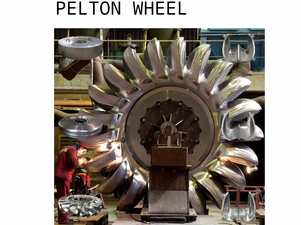
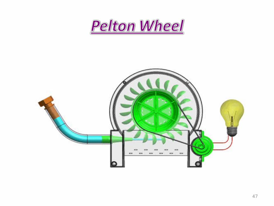
PELTON WHEEL
47
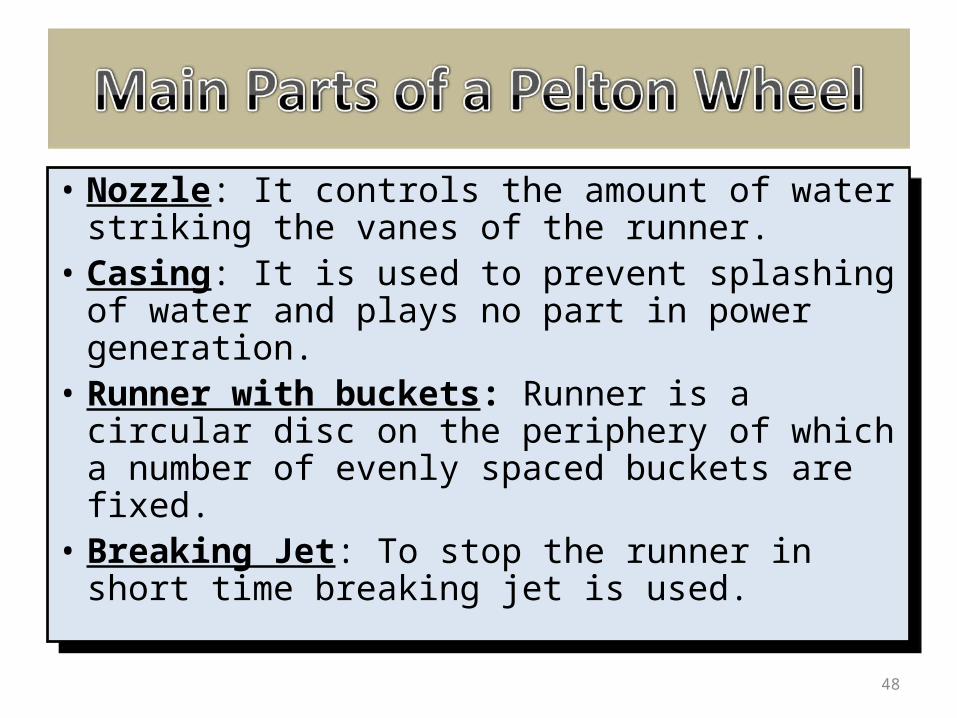
• Nozzle: It controls the amount of water striking the vanes of the runner.
• Casing: It is used to prevent splashing of water and plays no part in power generation.
• Runner with buckets: Runner is a circular disc on the periphery of which a number of evenly spaced buckets are fixed.
• Breaking Jet: To stop the runner in short time breaking jet is used.
48
• The high speed water coming out of the nozzle strikes the splitter which divides the jet into two equal streams. These stream flow along the inner curve of the bucket and leave it in the direction opposite to that of incoming jet. The high pressure water can be obtained from any water body situated at some height or streams of water flowing down the hills.
• The change in momentum (direction as well as speed) of water stream produces an impulse on the blades of the wheel of Pelton Turbine. This impulse generates the torque and rotation in the shaft of Pelton Turbine.
49
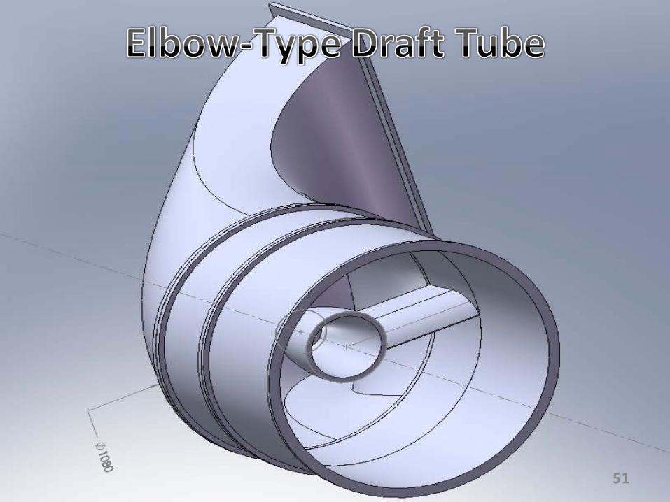
• The draft tube is a pipe of gradually increasing area which connects the outlet of the runner with the tailrace. One end of the draft tube is connected to the outlet of the runner while the other end is submerged below the level of water in the tail race.
• It creates a negative head at the outlet of the runner thereby increasing the net head on the turbine.
• It converts a large proportion of rejected kinetic energy into useful pressure energy
50
51
It is the operation by which the speed of the turbine is kept constant under all conditions of working load.
This is done automatically by a governor which regulates the rate flow through the turbines according to the changing load conditions on the turbine.
Governing of a turbine is absolutely necessary if the turbine is coupled to an electric generator which is required to run at constant speed under all fluctuating load conditions.
52
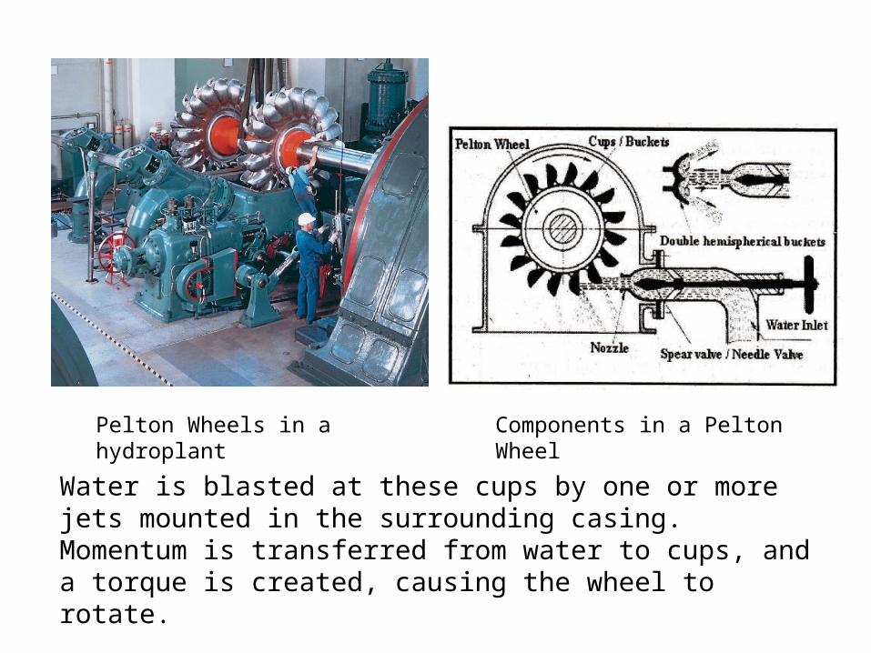
Pelton Wheels in a hydroplant Components in a Pelton Wheel
Water is blasted at these cups by one or more jets mounted in the surrounding casing. Momentum is transferred from water to cups, and a torque is created, causing the wheel to rotate.
This type of turbine is highly efficient.

54
55
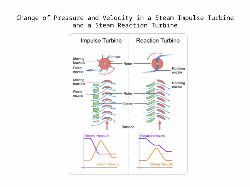
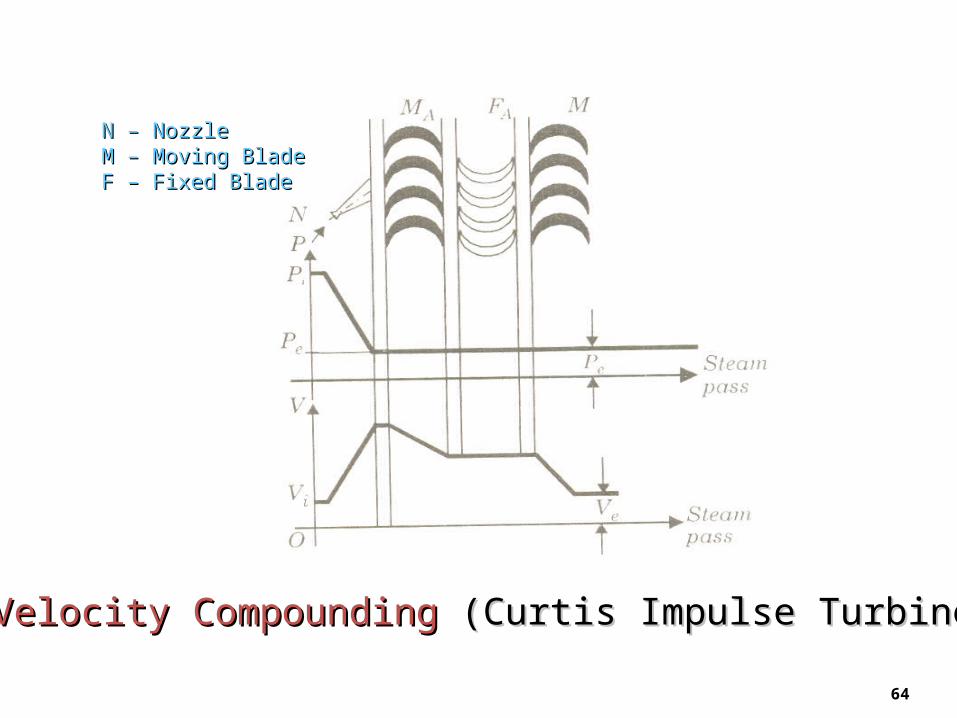
Change of Pressure and Velocity in a Steam Impulse Turbine and a Steam Reaction Turbine
59
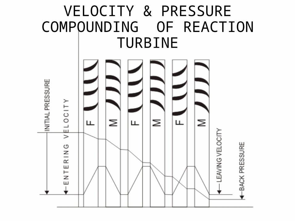
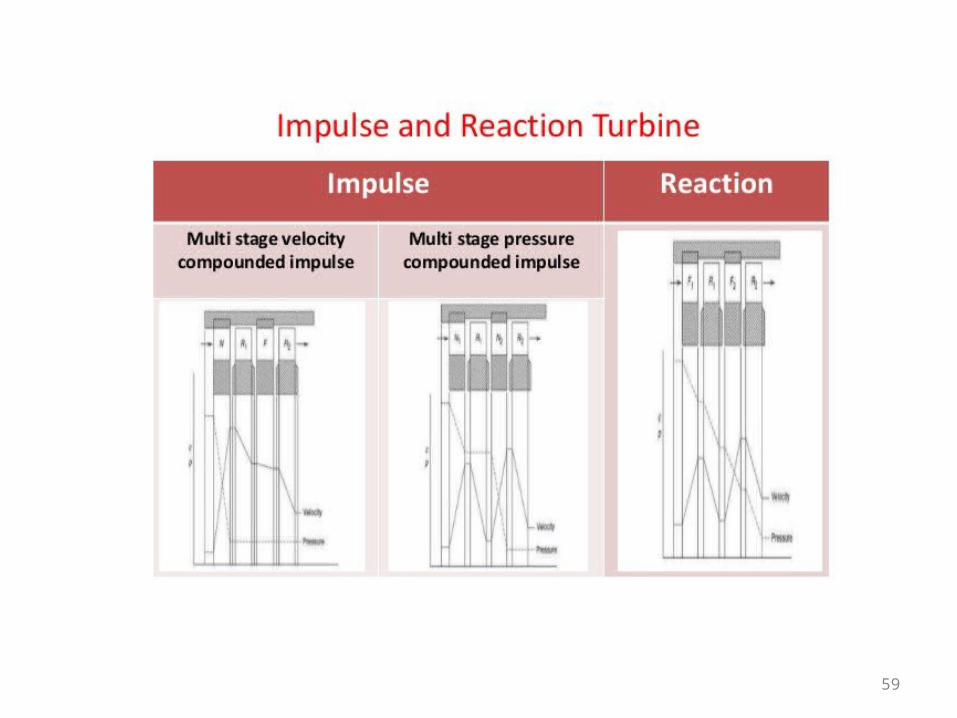
VELOCITY & PRESSURE COMPOUNDING OF REACTION TURBINE
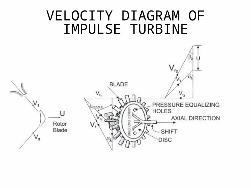
VELOCITY DIAGRAM OF IMPULSE TURBINE
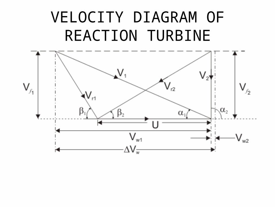
VELOCITY DIAGRAM OF REACTION TURBINE
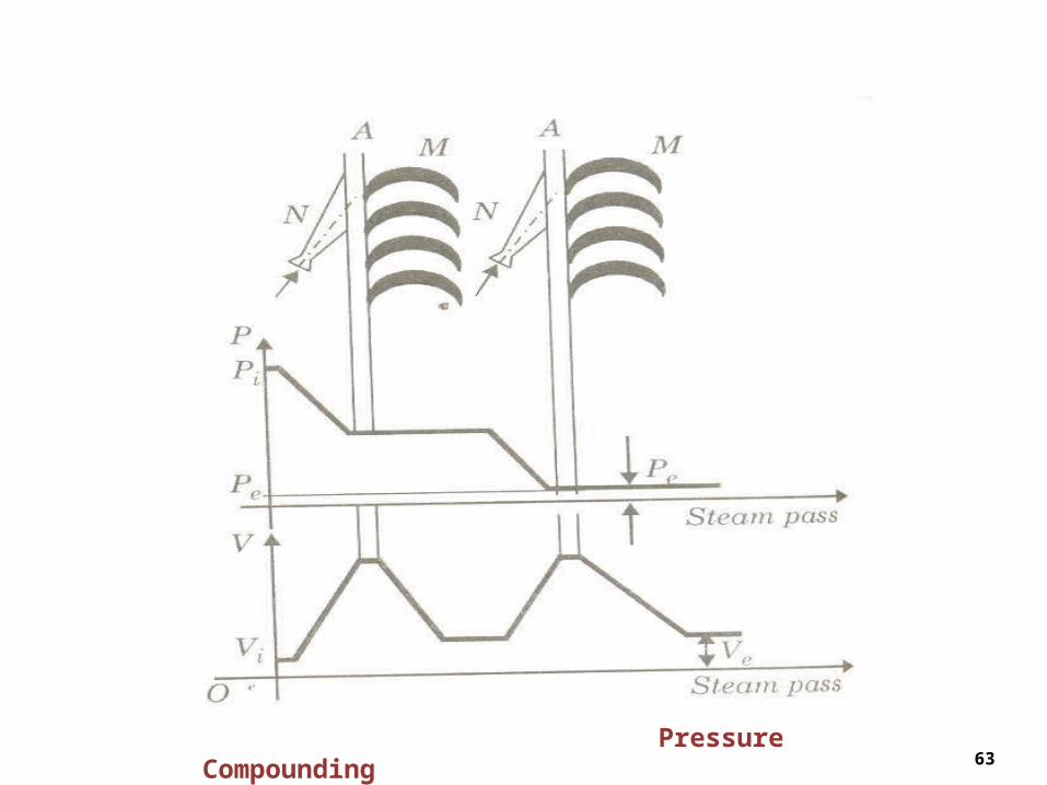
63 Pressure Compounding
64
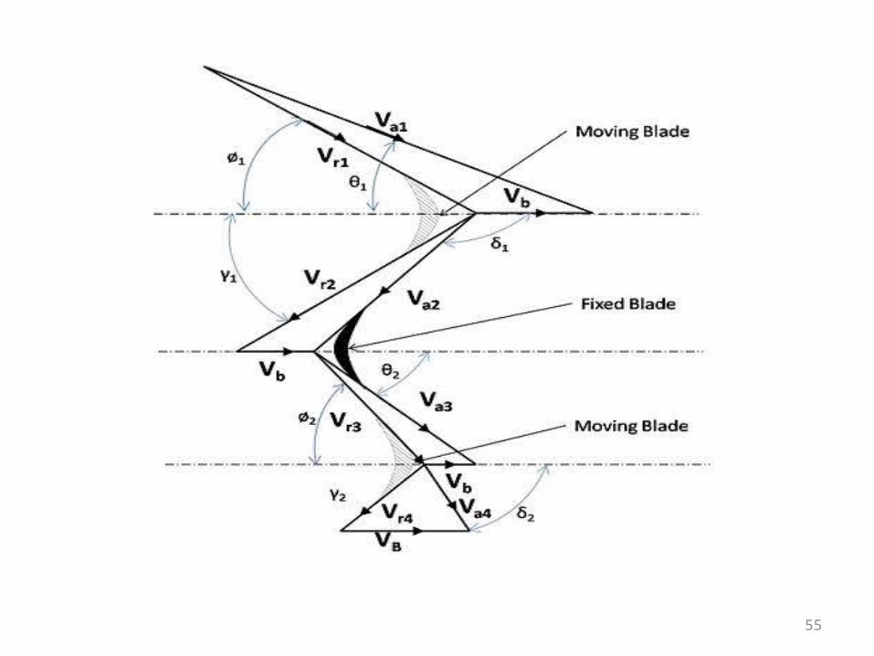
Velocity Compounding Velocity Compounding (Curtis Impulse Turbine)(Curtis Impulse Turbine)
N – NozzleN – NozzleM – Moving BladeM – Moving BladeF – Fixed BladeF – Fixed Blade
Characteristic curves of a Turbine
• These are curves which are characteristic of a particular turbine which helps in studying the performance of the turbine under various conditions. These curves pertaining to any turbine are supplied by its manufacturers based on actual tests.
• The data that must be obtained obtained in testing a turbine are the following:
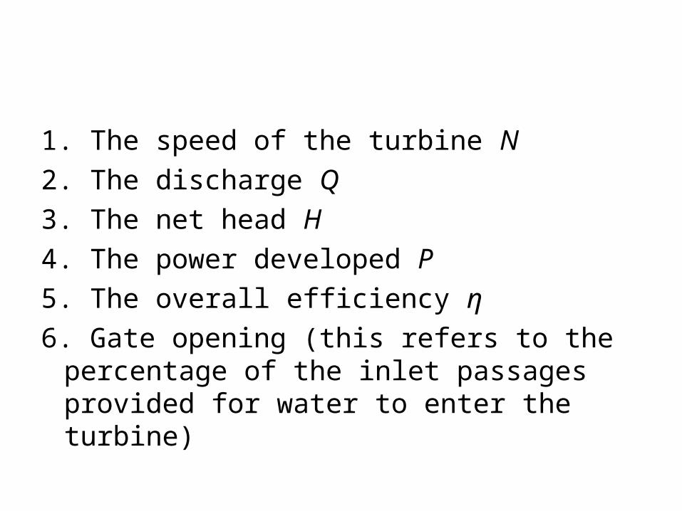
1. The speed of the turbine N2. The discharge Q3. The net head H4. The power developed P5. The overall efficiency η6. Gate opening (this refers to the percentage of
the inlet passages provided for water to enter the turbine)

• The characteristic curves obtained are the following:
• a) Constant head curves or main characteristic curves
• b) Constant speed curves or operating characteristic curves
• c) Constant efficiency curves or Muschel curves
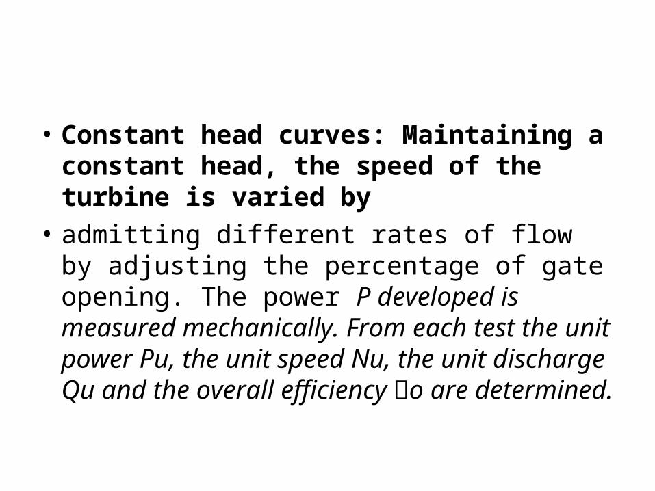
• Constant head curves: Maintaining a constant head, the speed of the turbine is varied by
• admitting different rates of flow by adjusting the percentage of gate opening. The power P developed is measured mechanically. From each test the unit power Pu, the unit speed Nu, the unit discharge Qu and the overall efficiency o are determined.
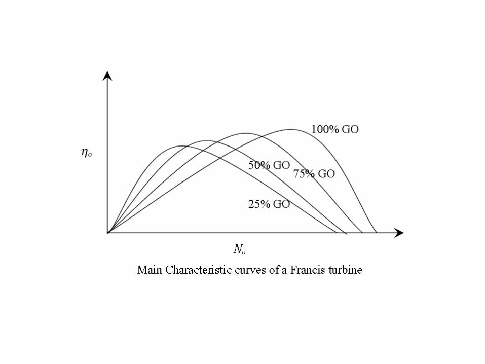
• The characteristic curves drawn are• a) Unit discharge vs unit speed• b) Unit power vs unit speed• c) Overall efficiency vs unit speed

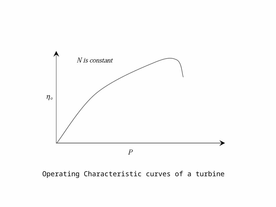
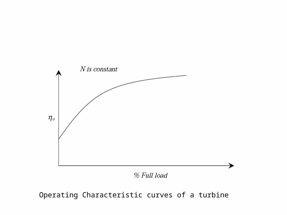
• Constant speed curves: In this case tests are conducted at a constant speed varying the
• head H and suitably adjusting the discharge Q. The power developed P is measured
• mechanically. The overall efficiency is aimed at its maximum value.
• The curves drawn are
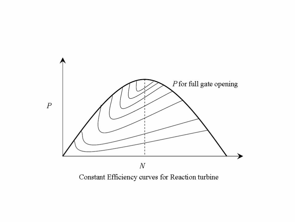
• Constant efficiency curves: These curves are plotted from data which can be obtained
• from the constant head and constant speed curves. The object of obtaining this curve is to
• determine the zone of constant efficiency so that we can always run the turbine with
• maximum efficiency.• This curve also gives a good idea about the
performance of the turbine at various• efficiencies.
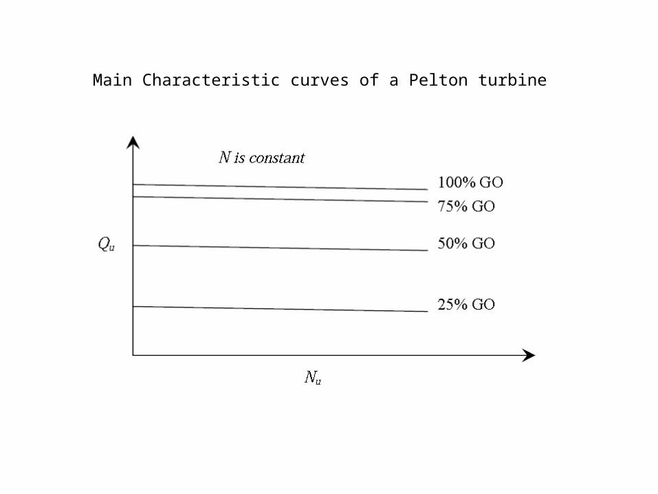
Main Characteristic curves of a Pelton turbine
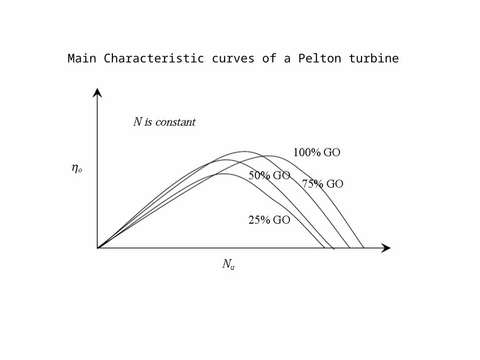
Main Characteristic curves of a Pelton turbine
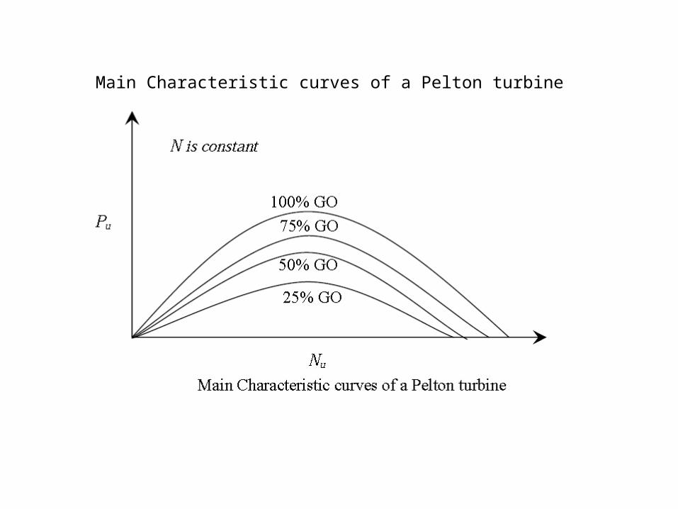
Main Characteristic curves of a Pelton turbine
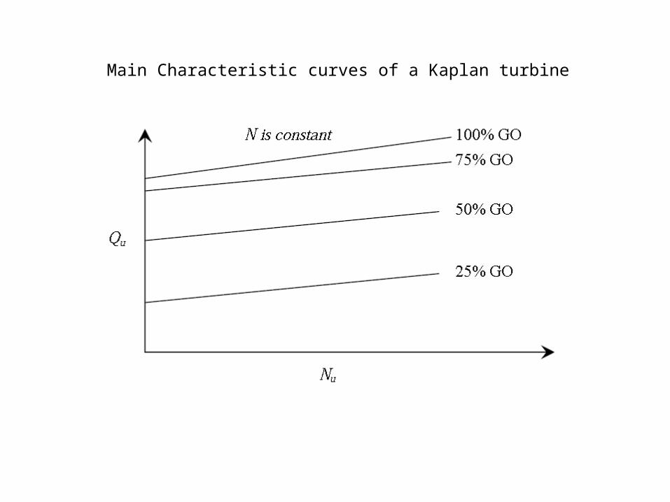
Main Characteristic curves of a Kaplan turbine
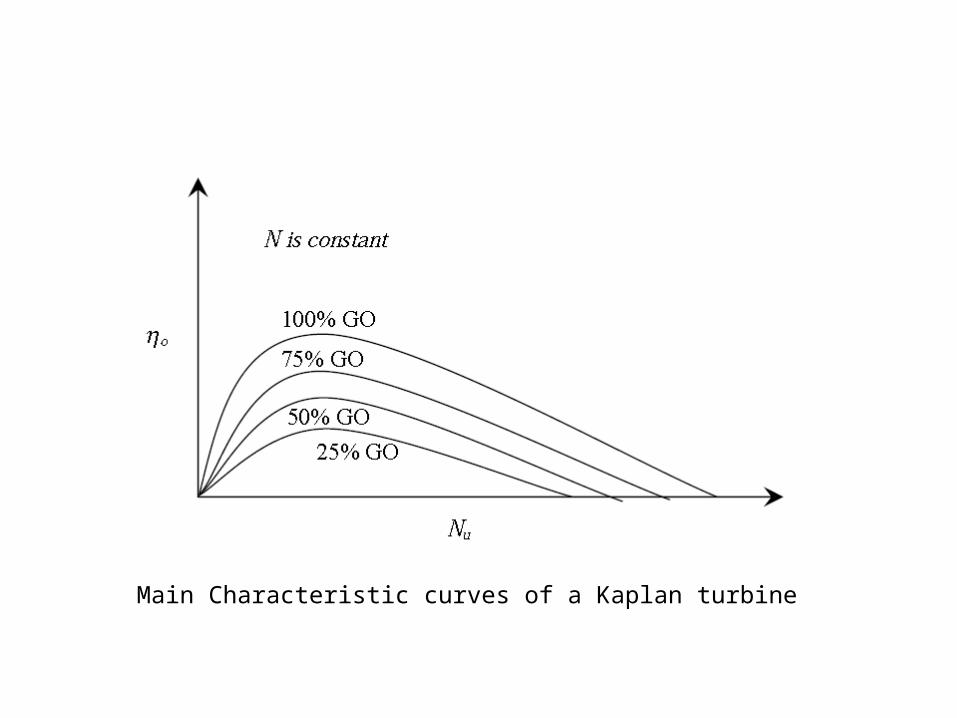
Main Characteristic curves of a Kaplan turbine

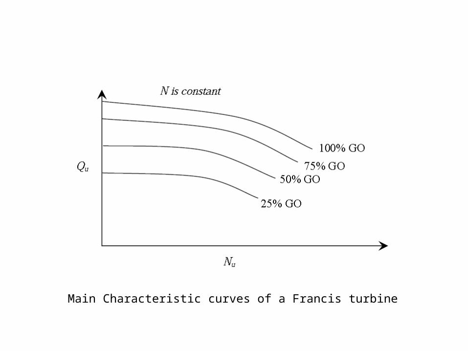
Main Characteristic curves of a Francis turbine
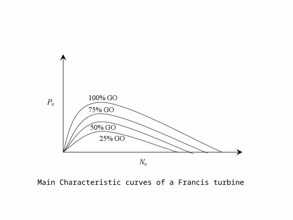
Main Characteristic curves of a Francis turbine
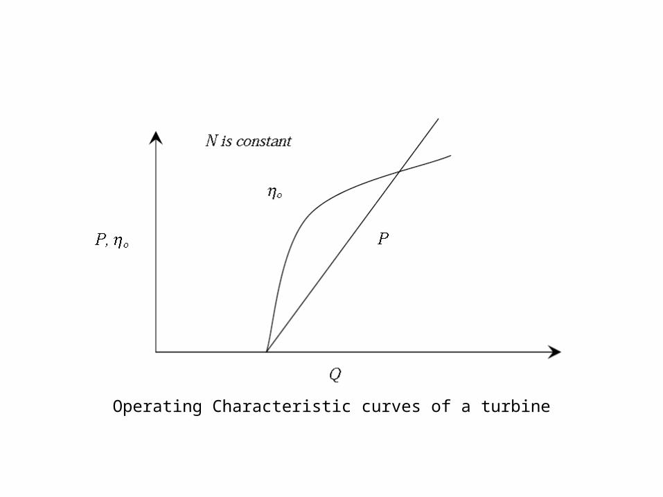
Operating Characteristic curves of a turbine
Operating Characteristic curves of a turbine
Operating Characteristic curves of a turbine
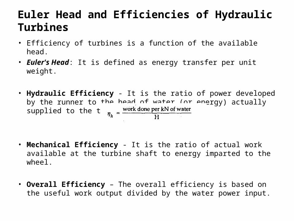
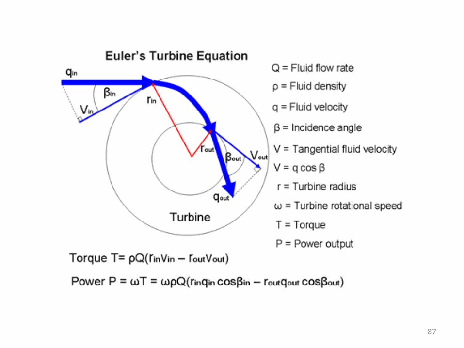
Euler Head and Efficiencies of Hydraulic Turbines
• Efficiency of turbines is a function of the available head.• Euler's Head: It is defined as energy transfer per unit weight.
• Hydraulic Efficiency - It is the ratio of power developed by the runner to the head of water (or energy) actually supplied to the turbine i.e.
• Mechanical Efficiency - It is the ratio of actual work available at the turbine shaft to energy imparted to the wheel.
• Overall Efficiency – The overall efficiency is based on the useful work output divided by the water power input.
87
88
COMPARISION OF TURBINES
In impulse turbines, the total head available is first converted into the kinetic energy.
In the reaction turbines, the fluid passes first through a ring of stationary guide vanes in which only part of the available total head is converted into kinetic energy.
The guide vanes discharge directly into the runner along the whole of its periphery, so that the fluid entering the runner has pressure energy as well as kinetic energy. The pressure energy is converted into kinetic energy in the runner.
89
90
COMPARISION OF TURBINES
91
VIDEOS

92