
Applications of piezo-actuated micro-robots in micro...
8
1 Applications of piezo-actuated micro-robots in micro-biology and material science J.-M. Breguet, W. Driesen, F. Kaegi, T. Cimprich Laboratoire de Systèmes Robotiques, Ecole Polytechnique Fédérale de Lausanne (LSRO-EPFL) Switzerland [email protected] Abstract This paper presents a few examples of manipulators and micro-robots based on piezo-actuators developed during the last 4 years in the Laboratoire de Systèmes Robotiques (LSRO) at EPFL. Three working principles will be described (bender, inch-worm, inertial drives) and illustrated through examples for various applications (neurology, micro- biology, electro discharge machining, nano-material testing and assembly of carbon nanotubes. Our goal is to demonstrate that an innovative mechanical design can make it possible to realize extremely simple manipulators working in the nanometer range for applications in micro-biology and nanotechnologies. 1. Introduction Actuators based on piezoceramic materials are rapidly getting increased market shares over well established drive systems such as electromagnetic motors. Compared to the latter, piezo actuators have a very high power to weight ratio, and can therefore be scaled down well and be made very compact. They are the ideal candidates for applications where submicron accuracy and very fast response are necessary. The use of new materials, especially high quality ceramics, has made it possible to guarantee a lifespan of these actuators compatible with the most demanding industrial applications, such as the semiconductor industry. Several companies (Physik Instrumente, NANO CONTROL, Nanomotion, …) [1-3] are proposing innovative piezo- based actuators with long range and nanometer resolution capabilities. Motors based on the ultrasonic principle remain the most common, but more and more products based on inertial drives or walking mechanisms are now also available (SmartAct, Piezomotor, …) [4, 5]. The Laboratoire de Systèmes Robotiques, has been active since more than 10 years in research on piezo actuators. Our goal is to demonstrate that an innovative mechanical design can make it possible to realize extremely simple manipulators working in the nanometer range for applications in nanotechnologies or micro-biology. This paper presents a few examples of manipulators and micro-robots developed during the last 4 years in our laboratory and shows a few applications. Three configurations of piezoelectric actuators (piezo tube, shear piezo, monolithic push-pull actuator) and various solutions for increasing the actuation range through amplification (bender) or stepping motion (inertial drive, inch-worm, ultrasonic) are described and illustrated through examples for various applications (neurology, micro-biology, nano material testing, assembly of carbon nanotubes, electro-discharge machining). y x OD ID L Typical specifications: L = 30 mm OD = 3.2 mm ID = 2.2 mm X, Y deflection = 6 μm @ 200V Axial deflection = 0.6 μm @ 200 V Natural frequency = 1’500 Hz Fig. 1: Bimorph [1] Fig. 2: Piezotube [1] 2. Actuator configuration: Piezo tube element 2.1. Amplification principle: Bimorph or bender actuator It is well known that piezo materials’ strain is limited to a few ppm. Several solutions can be proposed to amplify this movement. A very popular one is the bender, or bimorph configuration, composed of a piezo layer and a metal layer (Fig. 1). The piezo layer elongates or contracts while the metal layer is passive. The resulting strain bends the actuator. A piezotube features similar behavior: application of an opposite voltage to two opposite tube halves results into a
Transcript of Applications of piezo-actuated micro-robots in micro...

1
Applications of piezo-actuated micro-robots in micro-biology and material science
J.-M. Breguet, W. Driesen, F. Kaegi, T. Cimprich
Laboratoire de Systèmes Robotiques, Ecole Polytechnique Fédérale de Lausanne (LSRO-EPFL)
Switzerland
[email protected] Abstract This paper presents a few examples of manipulators and micro-robots based on piezo-actuators developed during the last 4 years in the Laboratoire de Systèmes Robotiques (LSRO) at EPFL. Three working principles will be described (bender, inch-worm, inertial drives) and illustrated through examples for various applications (neurology, micro-biology, electro discharge machining, nano-material testing and assembly of carbon nanotubes. Our goal is to demonstrate that an innovative mechanical design can make it possible to realize extremely simple manipulators working in the nanometer range for applications in micro-biology and nanotechnologies. 1. Introduction Actuators based on piezoceramic materials are rapidly getting increased market shares over well established drive systems such as electromagnetic motors. Compared to the latter, piezo actuators have a very high power to weight ratio, and can therefore be scaled down well and be made very compact. They are the ideal candidates for applications where submicron accuracy and very fast response are necessary. The use of new materials, especially high quality ceramics, has made it possible to guarantee a lifespan of these actuators compatible with the most demanding industrial applications, such as the semiconductor industry. Several companies (Physik Instrumente, NANO CONTROL, Nanomotion, …) [1-3] are proposing innovative piezo-based actuators with long range and nanometer resolution capabilities. Motors based on the ultrasonic principle remain the most common, but more and more products based on inertial drives or walking mechanisms are now also available (SmartAct, Piezomotor, …) [4, 5]. The Laboratoire de Systèmes Robotiques, has been active since more than 10 years in research on piezo actuators. Our goal is to demonstrate that an innovative mechanical design can make it possible to realize extremely simple manipulators working in the nanometer range for applications in nanotechnologies or micro-biology. This paper presents a few examples of manipulators and micro-robots developed during the last 4 years in our laboratory and shows a few applications. Three configurations of piezoelectric actuators (piezo tube, shear piezo, monolithic push-pull actuator) and various solutions for increasing the actuation range through amplification (bender) or stepping motion (inertial drive, inch-worm, ultrasonic) are described and illustrated through examples for various applications (neurology, micro-biology, nano material testing, assembly of carbon nanotubes, electro-discharge machining).
yx
OD
ID
L
Typical specifications:
L = 30 mm OD = 3.2 mm ID = 2.2 mm X, Y deflection = 6 μm @ 200V Axial deflection = 0.6 μm @ 200 V Natural frequency = 1’500 Hz
Fig. 1: Bimorph [1] Fig. 2: Piezotube [1] 2. Actuator configuration: Piezo tube element 2.1. Amplification principle: Bimorph or bender actuator It is well known that piezo materials’ strain is limited to a few ppm. Several solutions can be proposed to amplify this movement. A very popular one is the bender, or bimorph configuration, composed of a piezo layer and a metal layer (Fig. 1). The piezo layer elongates or contracts while the metal layer is passive. The resulting strain bends the actuator. A piezotube features similar behavior: application of an opposite voltage to two opposite tube halves results into a

2
bending of the tube. An arrangement with four electrodes allows for three degrees of freedom (two bending modes and one axial mode) (Fig. 2). Such actuators are well adapted for medium range strain (typically a few tens of μm) and presents a good dynamical behavior. The natural frequency of the tube presented in figure 2 is typically 1.5 kHz. 2.1.1. Application: Whisker stimulator By mechanically exciting a whisker of a mouse, interesting information can be collected on the neuronal response [6]. We were mandated by the Sensory Processing Laboratory (LSENS) at EPFL to develop a special device for this research. The main specification was to provide an actuator with 2 degrees of freedom (DOF) for generation of fast pulses (typically 1 ms) with a stroke of 100 μm. This device takes advantage of the high dynamic of a piezotube. The movement is further amplified with a long tip attached to the piezotube. The prototype shown in figure 3 has a natural frequency of 1 kHz.
mouse
w hisker
w hisker stimulator
Fig. 3: Whisker stimulator (left) and mouse-whisker attached to prototype (Prof. C. Petersen courtesy) (right)
3.5 ms impulse, 40μm@120Vp2p 1 ms impulse, 90μm@120Vp2p 1 ms impulse with shaper, 30μm@60Vp2p
Fig. 4: Whisker stimulator response to a sine wave excitation (left and center) and to input-shaped signal (right)
Fig. 4 shows the mechanical response of the device to an electrical impulse. On the left, the input signal is a 3.5 ms impulse with a sine wave shape (1 period). When the excitation frequency comes near to its mechanical natural frequency, the whisker stimulator’s response shows a large oscillation (Fig. 4, center). Using input shaping [7], the system can generate 1 ms pulses without any significant residual vibrations (Fig. 4, left). Input shaping is an interesting solution to overcome the mechanical limitations of a system [8]. 2.2. Stepping principle: Stick & Slip actuator and impact drive For an actuator range of several mm and more, an amplification based on a bender configuration is not sufficient anymore. The more significant increase in actuation range can be obtained through the application of a some kind of stepping principle such as the stick & slip or the impact drive principle [9-11]. Stick & Slip principle: an inertial mass (slider) is supported and guided by deformable legs (Fig. 5, left). Two modes of operation are possible: stepping- and scanning mode. In the stepping mode, each step consists of a slow deformation of the legs followed by an abrupt jump backwards. During the slow deformation, the mass follows the legs because of friction (stick), whereas it cannot follow the sudden jump because of its inertia (slip). The stepping-mode allows long displacements at a relatively high velocity (typically up to 5 mm/s). The resolution is limited to a step (typically 200-400nm). Once the position is within less than a step distance of the target, the legs are deformed slowly until the final position is reached. In this mode, called scanning-mode, the resolution is a fraction of a step (a few nm). An impact drive consists on three components: the main body, the actuator and the inertial (counter) weight. The main body is resting on the guiding surface with only the friction acting between both surfaces (Fig. 6). The motion is obtained as follows [10]: Starting from a completely extended (contracted) state, the actuator makes slow contraction (extension) causing an inertial force that does not exceed the static friction between main body and guiding surface. The main body keeps the position. At the end of the actuator range, the slow contraction (extension) is suddenly reversed into a very fast extension (contraction), resulting into an inertial force higher than the static friction, with a small step of the main body as a result.
input output
input output output

3
Both stick & slip actuators and impact drives are classified under the term “inertial drives”. In fact the essential difference between both stepping principles is just a matter of the mass ratio between the main body and the inertial mass. Moreover, stick & slip drives are mostly driven with saw tooth signals, while impact drives typically feature some kind of quadratic signal shape.
t
Elongation of tube (slow )
Initial position
PZT-tube (cut view )shaf t-guide
shaf t
Direction of movement
1 Step
Friction
Slow movem
Fast move
Point of rotation
Slip
Stick
Fig. 5: Stick & Slip (left) and impact drive (right)
working principles Fig. 6: Stick & Slip (left) and impact drive (right)
implemented with a piezotube 2.2.1. Application: 3 DOF manipulator The performances of the whisker stimulator described above have been improved in terms of working space using stepping motion generated with the piezo tube. Stick & Slip principle is used in the longitudinal direction of the piezotube, while impact drive is implemented for rotational movements (Fig. 6). Figure 7 show a first demonstrator that has been realized as proof of concept. It has 3DOF (two rotations and one translation). The end effector, e.g. a patch-clamp needle, is positioned with high speed (5mm/s) and high accuracy (<1μm) in a large working space (several cm3). The mechanical design can be much improved and simplified, but there are still some limitations to overcome. Right now there are no sensors integrated in the system and conventional sensors would limit the miniaturization. Also the control of the tip movement can be further enhanced using input-shaping as has been shown above in order to eliminate the needle vibrations.
Fig. 7: First demonstrator of the 3DOF manipulator
based on piezotube Fig. 8: Conceptual design of two manipulators working in
cooperation to make complex manipulation tasks
3. Actuator configuration: Shear mode piezo element If the excitation electrical field is applied perpendicular to the polarization field a piezoelectric element features a deformation in shear mode. Shear mode piezo actuators are often used for stick & slip actuators. 3.1. Stepping principle: Stick & Slip actuator based on shear mode piezo element The shear mode piezo is well adapted to be used in linear stages where space is the limiting factor. The actuator consists only of a substrate, a shear-mode piezo element, a mechanical contact interface and a moving part (Fig. 5, left). The contact interface acts as a guidance rail making the stage simple and compact. With a preload system, either magnetic or with an elastic element, a thrust force of a few Newtons is possible. On the other hand, only one degree of freedom per piezo layer is possible.
Fig. 9: 6 DOF system consisting of two cartesian manipulators (XYZ)
Fig. 10: Set up used for the assembly of multi walled carbon nanotube on AFM tips

4
3.1.1. Application: 6 DOF for micro handling and micro assembly in SEM Two cartesians 3 DOF manipulators have been designed for the assembly of multi walled carbon nanotubes (MWCNT) on AFM tips (Fig. 9). The CNTs have been grown on a razor blade that is fixed on one of the manipulator while the AFM tip is fixed on the opposite one (Fig. 10). Using the integrated sensors (50 nm resolution) and a visual feedback of the SEM the tip is brought into position and the CNT is fixed to the tip using deposition by focusing the electron beam on the desired region. The “coarse” approach is done automatically while the final alignment is still a telemanipulated task (Fig. 11) [12]. However, new research is conducted in the frame of the European project Nanohand [13] to make this assembly fully automatic.
Fig. 11: From left to right: alignment of the CNT with the AFM tip,
attachment of the CNT and separation of the CNT from the razor blade [12]
3.1.2. Application: Micro-indenter for nano material-testing in SEM The SEM environment induces several constraints. In addition to SEM compatibility (vacuum, electron beam, …) the set-up must allow an unhindered view of the indentation region. The indentation tip axis that is perpendicular to the sample surface has therefore to be inclined with respect to the beam axis of the SEM. The indenter device developed at LSRO [14] is compact in order to fit into a standard SEM chamber. All materials are vacuum compatible and the device is shielded electro-magnetically such that the SEM measurements are not disturbed.
Fig. 12: The LSRO SEM-Micro-Indenter: 1 load cell; 2 XY-positioning table; 3 sample holder; 4 tip holder and adapter; 5 piezo actuator, displacement sensor; 6 sample
coarse positioning.
Fig. 13 : a) Load displacement curve and b) SEM micrographs of an indentation with a wedge 60° indenter [14]
The indentation head (4) is composed of a mechanism with flexure hinges that holds the diamond tip. The head is driven by a stack piezo (5) with 20 μm range and integrated displacement sensor (strain gauge). The indentation head and its actuator are assembled on a coarse positioning stage (6) (also a flexure mechanism) and driven by a fine pitch precision screw, remotely controlled with a cable connected to a knob installed on the SEM chamber’s door. The stage is fixed on the main body by a dovetail sliding bearing. This mechanism allows testing samples with diverse heights using different load cells (with various sizes). An XY-stage (2) holds the load cell (1) and the sample (3). A stick-slip actuator drives the X-axis that is guided by a set of linear bearings. The range is 10mm and the nominal step size is 200nm. In addition this axis can also be used to scratch the sample with a maximum driving force of 200mN. The Y-axis also has a non-motorized 10mm coarse range and a fine adjustment with a stack piezo (not visible on the picture). This allows scratching the sample in the Y-direction over a range of 20mm, with high forces and high resolution. This device is regularly used by scientists at the EMPA-Thun for fundamental research on material science. A typical example is the study of cracks initiation and propagation during indentation in semi-conductor materials (Fig. 13) [15]. 3.2. Stepping principle: Inch-worm actuator Inch-Worm® principle is a well known system that has been proposed several years ago [16]. A similar system was proposed by S. Pan [17] that makes the device easier to fabricate. Contrary to the Inch-worm that is generally composed of two active clamps which relative position can be modified, Pan’s system relies on four passive clamps that will move all together in one direction while they will come back one after the other. Figure 14 (left) shows this working principle for a device based on shear-mode piezos.

5
3.2.1. Application: Micro electrode feeder for electro-discharge machining LSRO has applied Pan’s principle to move a small electrode very accurately for micro electro discharge machining (Micro-EDM). The main benefits are that the system automatically adapts to a large range of electrodes’ diameter (50 to 1’500 μm), the electrode is very well guided and the clamps can be used for electrically connection of the electrode. Moreover, the system is mechanically very simple, reliably and can be made very compact (Fig. 14, right). The industrial design has been further simplified (Fig. 15) using monolithic push-pull actuators (MPA), described in the next paragraph. Direction of advancing
electrode Shear mode PZT
1 step
electrode
Main specifications: Velocity 1 mm/s Resolution 50 nm Force 500 mN Electrode diameter 50 to 1’500 μm Dimension 30 x Ø12 mm
Fig. 14: Inch worm working principle and conceptual design of an electrode feeder
Fig. 15: Industrial prototype of the micro electrode feeder
4. Actuator configuration: Monolithic push-pull actuators (MPA) In order to further simplify the fabrication of micro-manipulator based on piezo actuators, LSRO has developed the monolithic push-pull actuator MPA [18]. Electrodes are patterned by screen-printing or lift-off methods on a piezo-ceramic substrate in a way that two or more segments, separated by small gaps, form the electrode arrangement for one actuator. In the simplest case, i.e. for a one-dimensional movement, two half-circles are arranged as shown in figure 16. The other side of the substrate may be patterned in the same way or covered completely by an electrode carrying the ground potential. When both electrode halves are actuated with an opposite voltage (typically +150V and -150V), an elongation in one segment and a contraction in the other segment of the actuator result into an in-plane lateral displacement of the contact point (e.g. sapphire half-sphere) (fig. 16).
Fig. 16: monolithic push-pull actuator description (left),
lateral view (right). Fig. 17: exploded view and prototype of a linear stage
based on monolithic push-pull actuators [18] 4.1. Stepping principle: MPA in Stick & Slip mode The MPA can operate in three different modes: Inch-worm, Stick & Slip and ultrasonic. A combination of the MPA and the inch-worm principle has been implemented in a second version of the micro electrode feeder described in paragraph 3.2.1, but is not further described here because it is patented. The next paragraph briefly describes micro-robots actuated by MPA in Stick & Slip mode. 4.1.1. Application: Micro-robots based on MPA actuators Figure 17 shows an exploded view and prototype of a linear stage where 3 actuators have been screen-printed on one piezoelectric substrate. The linear guiding of the slider is guaranteed by the use of 2 precision shafts sliding on two sapphire half-spheres. A preload is given by a permanent magnet [18]. The same principle was used to make a rotary stage. Figure 18 (left) shows the side of a mobile micro-robot where the disposition in a circular way of 3 pairs of half circles allows a rotating motion. Figure 18 (right) shows the same robot with mounted tool (micro-needle) which is preloaded by a mechanical spring. Several micro-robots such as the one shown in figure 18, have been fabricated and are integrated in micro-manipulation platform [19, 20]. Several degrees of freedom can be obtain in a single piezo-ceramic layer by patterning a circular electrode divided in 4 equivalent segments as shown in figure 19. This disposition allows to make X and Y motion of the sapphire half-sphere by switching the actuated electrode couples.
Electrode Clamps and shear-mode piezo elements

6
These 2 DOF monolithic piezo actuators provide a high degree of integration, low-cost batch process fabrication as well as miniaturization capability. Figure 19 shows a complete sheet of piezoelectric material with screen-printed electrode. MPA can therefore reliably be produced at low cost and easily be custom tailored.
1 cm
Fig. 18: Micro-robot with a rotary actuator for vertical positioning of micro-tools (e.g. micro-needle, micro-
tweezers, micro-pipette). The rotor is preloaded with a leaf spring [19]
Fig. 19: top left: principle of monolithic push-pull actuators for 2 DOF. Top right: piezo-ceramic sheet with patterned electrodes. Bottom: example of a 2 degrees of
freedom MPA, packaged and with its connector The 2 DOF MPA of figure 19 can be integrated in various manipulators, more or less complex. A nice example of what can be achieved is the micro-robot shown in figure 20. This robot has 3 DOF allowing positioning accurately a micro-tool in a workspace of about 3 cubic centimeters. Most of the parts can easily be fabricated by laser machining and assembled like Lego blocks. The robot is equipped with 2 sensors based on low cost CCD camera and a special target pattern. Each sensor can measure three degrees of freedom (two translations and one rotation) with submicron accuracy. Future development will permit to further miniaturize the sensor and to increase its resolution. Moreover, a special pattern on the target will make it possible to obtain absolute position information.
Fig. 20: a) prototype of a 4 degrees of freedom manipulator used in the
field of a microscope in microbiology b) disposition of several manipulators under a microscope
This micro-robot was specially designed for applications in micro-biology, and more specifically for micro-patch clamping. Micro-patch clamping consists on positioning accurately micro-electrodes on several cells simultaneously in order to apply an electrical signal and measure the response of the other cells. In this application it is important to be able to arrange a large number of robots under the microscope. The compact design proposed allows for up to 15 robots to work together on the stage of a commercial inverted microscope (Fig. 20).
Fig. 21: (right) Scheme of leg movement in ultrasonic mode with two sinus
signals with a phase shift of 90°. (bottom) the corresponding positions of the leg tip in the ellipse. (left) Mechanical design of the linear stage
Fig. 22: Several steps of less than 4nm done in open-loop with 2 sinus periods (φ = 900, 15 kHz, 80 Vp2p)
7
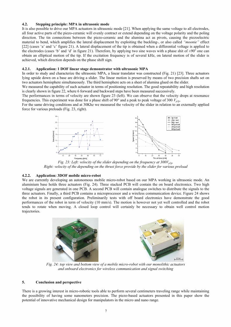
4.2. Stepping principle: MPA in ultrasonic mode It is also possible to drive our MPA actuators in ultrasonic mode [21]. When applying the same voltage to all electrodes, all four active parts of the piezo-ceramic will evenly contract or extend depending on the voltage polarity and the poling direction. The tin connections between the piezo-ceramic and the alumina act as pivots, causing the piezoelectric material to bend, which amplifies the lateral displacement by exploiting the buckling-, or also called “moonie” effect [22] (cases ‘a’ and ‘c’ figure 21). A lateral displacement of the tip is obtained when a differential voltage is applied to the electrodes (cases ‘b’ and ‘d’ in figure 21). Therefore, by applying two sine waves with a phase shit of ±90o one can obtain an elliptical motion of the tip. If the excitation frequency is of several kHz, on lateral motion of the slider is achieved, which direction depends on the phase shift sign. 4.2.1. Application: 1 DOF linear stage demonstrator with ultrasonic MPA In order to study and characterize the ultrasonic MPA, a linear translator was constructed (Fig. 21) [23]. Three actuators lying upside down on a base are driving a slider. The linear motion is preserved by means of two precision shafts set on two actuators hemisphere simultaneously. The third hemisphere acts on a sheet of alumina glued on the slider. We measured the capability of such actuator in terms of positioning resolution. The good repeatability and high resolution is clearly shown in figure 22, where 6 forward and backward steps have been measured successively. The performances in terms of velocity are shown figure 23 (left). We can observe that the velocity drops at resonance frequencies. This experiment was done for a phase shift of 90° and a peak to peak voltage of 300 Vp2p. For the same driving conditions and at 30Khz we measured the velocity of the slider in relation to an externally applied force for various preloads (Fig. 23, right).
Fig. 23: Left: velocity of the slider depending on the frequency at 300Vp2p.
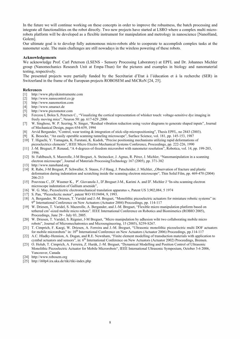
Right: velocity of the depending on the thrust force provide by the slider for various preload 4.2.2. Application: 3DOF mobile micro-robot We are currently developing an autonomous mobile micro-robot based on our MPA working in ultrasonic mode. An aluminium base holds three actuators (Fig. 24). Three stacked PCB will contain the on board electronics. Two high voltage signals are generated in one PCB. A second PCB will contain analogue switches to distribute the signals to the three actuators. Finally, a third PCB contains a microprocessor and a wireless communication device. Figure 24 shows the robot in its present configuration. Preliminarily tests with off board electronics have demonstrate the good performances of the robot in term of velocity (10 mm/s). The motion is however not yet well controlled and the robot tends to rotate when moving. A closed loop control will certainly be necessary to obtain well control motion trajectories.
Fig. 24: top view and bottom view of a mobile micro-robot with our monolithic actuators
and onboard electronics for wireless communication and signal switching 5. Conclusion and perspective There is a growing interest in micro-robotic tools able to perform several centimeters traveling range while maintaining the possibility of having some nanometers precision. The piezo-based actuators presented in this paper show the potential of innovative mechanical design for manipulators in the micro and nano range.
8
In the future we will continue working on these concepts in order to improve the robustness, the batch processing and integrate all functionalities on the robot directly. Two new projects have started at LSRO where a complex multi micro-robots platform will be developed as a flexible instrument for manipulation and metrology in nanoscience [NanoHand, Golem]. Our ultimate goal is to develop fully autonomous micro-robots able to cooperate to accomplish complex tasks at the nanometer scale. The main challenges are still nowadays in the wireless powering of these robots. Acknowledgements We acknowledge Prof. Carl Peterson (LSENS - Sensory Processing Laboratory) at EPFL and Dr. Johannes Michler group (Nanomechanics Research Unit at Empa-Thun) for the pictures and examples in biology and nanomaterial testing, respectively. The presented projects were partially funded by the Secrétariat d’Etat à l’éducation et à la recherche (SER) in Switzerland in the frame of the European projects ROBOSEM and MiCRoN [24, 25]. References [1] http://www.physikinstrumente.com [2] http://www.nanocontrol.co.jp [3] http://www.nanomotion.com [4] http://www.smaract.de [5] http://www.piezomotor.com [6] Ferezou I, Bolea S, Petersen C., “Visualizing the cortical representation of whisker touch: voltage-sensitive dye imaging in
freely moving mice”, Neuron 50: pp. 617-629 ,2006 [7] W. Singhose, W. P. Seering, N. Singer, “Resdual vibration reduction using vector diagrams to generate shaped inputs”, Journal
of Mechanical Design, pages 654-659, 1994 [8] Arvid Bergander, “Control, wear testing & integration of stick-slip micropositioning”, Thesis EPFL, no 2843 (2003). [9] K. Besocke, “An easily operable scanning tunneling microscope”, Surface Science, vol. 181, pp. 145-153, 1987 [10] T. Higuchi, Y. Yamagata, K. Furutani, K. Kudoh, “Precise positioning mechanisms utilizing rapid deformations of
piezoelectrics elements”, IEEE Micro Electro Mechanical Systems Conference, Proceedings, pp. 222-226, 1990 [11] J.-M. Breguet, P. Renaud, “A 4-degrees-of-freedom microrobot with nanometer resolution”, Robotica, vol. 14, pp. 199-203,
1996. [12] St. Fahlbusch, S. Mazerolle, J-M Breguet, A. Steinecker, J. Agnus, R. Pérez, J. Michler, “Nanomanipulation in a scanning
electron microscope”, Journal of Materials ProcessingTechnology 167 (2005), pp. 371-382 [13] http://www.nanohand.org [14] R. Rabe, J-M Breguet, P. Schwaller, S. Stauss, F-J Haug, J. Patscheider, J. Michler, „Observation of fracture and plastic
deformation during indentation and scratching inside the scanning electron microscope“, Thin Solid Film, pp. 469-470 (2004) 206-213
[15] Pouvreau C., Dr. Wasmer K., Pr. Giovanola J., Dr.Breguet J-M., Karimi A. and Dr. Michler J “In-situ scanning electron microscope indentation of Gallium arsenide”,
[16] W. G. May, Piezoelectric electromechanical translation apparatus », Patent US 3,902,084, 5 1974 [17] S. Pan, “Piezoelectic motor”, patent WO 9319494, 9, 1993. [18] A. Bergander, W. Driesen, T. Varidel and J.-M. Breguet, “Monolithic piezoelectric actuators for miniature robotic systems” in:
9th International Conference on New Actuators (Actuator 2004) Proceedings, pp. 114-117 [19] W. Driesen, T. Varidel, S. Mazerolle, A. Bergander, and J.-M. Breguet, “Flexible micro manipulation platform based on
tethered cm3-sized mobile micro robots”. IEEE International Conference on Robotics and Biomimetics (ROBIO 2005), Proceedings, June 29 – July 03, 2005.
[20] W. Driesen, T. Varidel, S. Régnier, J-M Breguet, ”Micro manipulation by adhesion wiht two collaborating mobile micro robots”, Journal of Micromechatronics and Microengineering, 15 (2005), S259-S267.
[21] T. Cimprich, F. Kaegi, W. Driesen, A. Ferreira and J.-M. Breguet, “Ultrasonic monolithic piezoelectric multi DOF actuators for mobile microrobots” in: 10th International Conference on New Actuators (Actuator 2006) Proceedings, pp.114-117
[22] A.C. Hladky-Hennion, A. Dogan, and R.E. Newnham, “Finite element modelling of transduction materials with application to cymbal actuators and sensors”, in: 6th International Conference on New Actuators (Actuator 2002) Proceedings, Bremen.
[23] O. Holub, T. Cimprich, A. Ferreira, Z. Hurák, J.-M. Breguet, “Dynamical Modelling and Position Control of Ultrasonic Monolithic Piezoelectric Actuator for Mobile Microrobots“, IEEE International Ultrasonic Symposium, October 3-6 2006, Vancouver, Canada
[24] http://www.robosem.org [25] http://i60p4.ira.uka.de/tiki/tiki-index.php


![[DESIGN] Piezo-Piezo to Pie](https://static.fdocuments.in/doc/165x107/5571f8bb49795991698df909/design-piezo-piezo-to-pie.jpg)

