Applications of Modeling and Simulation for Flight ... · PDF fileApplications of Modeling and...
10
Applications of Modeling and Simulation for Flight Hardware Processing at Kennedy Space Center Jessica L. Marshall Rensselaer Polytechnic Institute, Troy, NY 121801 I. Abstract The Boeing Design Visualization Group (DVG) is responsible for the creation of highly-detailed representations of both on-site facilities and flight hardware using computer-aided design (CAD) software, with a focus on the ground support equipment (GSE) used to process and prepare the hardware for space. Throughout my ten weeks at this center, I have had the opportunity to work on several projects: the modification of the Multi- Payload Processing Facility (MPPF) High Bay, weekly mapping of the Space Station Processing Facility (SSPF) floor layout, kinematics applications for the Orion Command Module (CM) hatches, and the design modification of the Ares I Upper Stage hatch for maintenance purposes. The main goal of each of these projects was to generate an authentic simulation or representation using DELMIA V5 software. This allowed for evaluation of facility layouts, support equipment placement, and greater process understanding once it was used to demonstrate future processes to customers and other partners. As such, I have had the opportunity to contribute to a skilled team working on diverse projects with a central goal of providing essential planning resources for future center operations. II. Introduction While traditionally CAD is used to design individual innovations from the ground up, it can also be used to model existing hardware as an important tool in the planning process. Its purpose is still the same: to aid in the visualization of ideas and concepts in order to gain a greater understanding of prospective options for resources. This is the mission of the Boeing DVG. When a facility, or customer, is looking to import new machinery into their current space or modify their existing hardware, they look to DVG to provide an accurate representation of the future operations and setups. This can be accomplished in terms of either stationary models or simulations of whole processes. This modeling helps customers to implement new hardware, enhance the decision-making process, and streamline their processes. Boeing DVG uses a CAD package created by Dassault Systemes, a French company that combined the modeling program CATIA V5 with the simulation program DELMIA V5. The main benefit of both software elements being produced by the same company is their compatibility with one another. Models can be created in CATIA and imported into DELMIA simulations while retaining all attributes with which they were originally designed. Additionally, the CATIA/DELMIA package is one of few existing CAD packages that can handle the large size of the final simulation files. As such, when DVG receives hardware that was designed in another CAD program, such as ProEngineer (Prof), the file is then translated into CATIA using a custom software package. Consistent use of the software allows for models to remain cohesive with one another given any future design modifications. Models created in CATIA can be anything from a single five-gallon bucket to an entire high bay. Models of facilities incorporate as many details as possible into the design, so as to provide a truly accurate representation of the actual, or what will be the actual, setup. Models of individual components are often created using photographs of existing machinery, engineering drawings, hand-drawn measurements, or point clouds from a laser scanner. These components are then compiled into full-facility models and used to plan for available space or modify current hardware locations. This practice can be also be used for flight hardware, systems, and vehicles, in order to represent operations for flight hardware processing on site. 1 NASA USRP Intern, Boeing Design Visualization Group, Kennedy Space Center https://ntrs.nasa.gov/search.jsp?R=20100031186 2018-05-11T14:36:44+00:00Z
Transcript of Applications of Modeling and Simulation for Flight ... · PDF fileApplications of Modeling and...

Applications of Modeling and Simulation for FlightHardware Processing at Kennedy Space Center
Jessica L. MarshallRensselaer Polytechnic Institute, Troy, NY 121801
I. AbstractThe Boeing Design Visualization Group (DVG) is responsible for the creation of highly-detailed
representations of both on-site facilities and flight hardware using computer-aided design (CAD) software, with afocus on the ground support equipment (GSE) used to process and prepare the hardware for space. Throughout myten weeks at this center, I have had the opportunity to work on several projects: the modification of the Multi-Payload Processing Facility (MPPF) High Bay, weekly mapping of the Space Station Processing Facility (SSPF)floor layout, kinematics applications for the Orion Command Module (CM) hatches, and the design modification ofthe Ares I Upper Stage hatch for maintenance purposes. The main goal of each of these projects was to generate anauthentic simulation or representation using DELMIA V5 software. This allowed for evaluation of facility layouts,support equipment placement, and greater process understanding once it was used to demonstrate future processes tocustomers and other partners. As such, I have had the opportunity to contribute to a skilled team working on diverseprojects with a central goal of providing essential planning resources for future center operations.
II. IntroductionWhile traditionally CAD is used to design individual innovations from the ground up, it can also be used to
model existing hardware as an important tool in the planning process. Its purpose is still the same: to aid in thevisualization of ideas and concepts in order to gain a greater understanding of prospective options for resources.This is the mission of the Boeing DVG. When a facility, or customer, is looking to import new machinery into theircurrent space or modify their existing hardware, they look to DVG to provide an accurate representation of thefuture operations and setups. This can be accomplished in terms of either stationary models or simulations of wholeprocesses. This modeling helps customers to implement new hardware, enhance the decision-making process, andstreamline their processes.
Boeing DVG uses a CAD package created by Dassault Systemes, a French company that combined themodeling program CATIA V5 with the simulation program DELMIA V5. The main benefit of both softwareelements being produced by the same company is their compatibility with one another. Models can be created inCATIA and imported into DELMIA simulations while retaining all attributes with which they were originallydesigned. Additionally, the CATIA/DELMIA package is one of few existing CAD packages that can handle thelarge size of the final simulation files. As such, when DVG receives hardware that was designed in another CADprogram, such as ProEngineer (Prof), the file is then translated into CATIA using a custom software package.Consistent use of the software allows for models to remain cohesive with one another given any future designmodifications.
Models created in CATIA can be anything from a single five-gallon bucket to an entire high bay. Modelsof facilities incorporate as many details as possible into the design, so as to provide a truly accurate representation ofthe actual, or what will be the actual, setup. Models of individual components are often created using photographsof existing machinery, engineering drawings, hand-drawn measurements, or point clouds from a laser scanner.These components are then compiled into full-facility models and used to plan for available space or modify currenthardware locations. This practice can be also be used for flight hardware, systems, and vehicles, in order torepresent operations for flight hardware processing on site.
1 NASA USRP Intern, Boeing Design Visualization Group, Kennedy Space Center
https://ntrs.nasa.gov/search.jsp?R=20100031186 2018-05-11T14:36:44+00:00Z

Another important element to accurate modeling is kinematics simulation. CATIA utilizes a kinematicspackage called Digital Mock Up (DMU) Kinematics. This workbench is used to add motion and simulationcommands to the model components while still in the CATIA program. An example of this is adding kinematicscommands to a model of a flight seat to allow for adjustments that will be made to the heights of the restraints forastronauts of different sizes. DMU Kinematics provides several different joint options that simulate realistic motionwith limits set by the user. This allows the user to replicate the motions of both individual components and entireproducts for use in simulations. It also allows for visualization of the commands and limits of each motion andhelps in determining the accessibility and clearances of the components when they are viewed in their respectivepositions.
These models, combined with their kinematics commands, are used to create simulations of the processesthat will be carried out by the customers. They are presented to the customers interactively using either DELMIAV5 or high-definition (HD) video files created using the software. These demonstrations allow customers to seetheir plans in a three-dimensional context. The DELMIA simulations illustrate the processes and show how theindividual hardware components will interact under the assigned scenarios. Meetings in which the simulations areshown allow for customers to give feedback and discuss issues and concerns based on the new representation.Ultimately, DELMIA allows the entire room to see the same "big picture" and thus ensure that everyone is on thesame page when discussing the future plans.
In working with DVG, my focus has been centered on four particular projects. The Multi-PayloadProcessing Facility (MPPF) is used for servicing equipment for space payloads, and is the planned center for futureOrion operations. Thus, the facility had to be reworked in order to provide the proper space and connections forOrion servicing operations and ground support. My objective was to modify the panels and additional componentsof the south wall of the MPPF High Bay according to the planned needs of the Orion program. This involvedtranslating locations of elements from both engineering drawings and ProE, creating new components as needed,and adding the appropriate textures taken from photographs of actual materials.
I was also involved in the weekly updating of the Space Station Processing Facility (SSPF) model. Eachweek the leads of the facility meet to discuss plans for adding, removing, or relocating hardware. In order to basedecisions off the most current data, members of DVG walk the SSPF High Bay and Intermediate (I) Bay and notethe location of each component in the facility. We then update the models using Design Vis software (a modelingprogram that works with CATIA and DELMIA) and produce drawings for the next week. These drawings are thenused to assess available space for prospective projects.
In terms of kinematics applications, I had the opportunity to work with the Orion Command Module (CM)and the Launch Abort System (LAS) in order to get the hatches to open and close. Each hatch is designed with asystem of complex hinges that must be operated simultaneously to recreate the realistic motion. It is necessary forsimulations of Orion servicing to have a modeled hatch capable of several positions in order to determine theaccessibility of the hatch from the service stands and design for the optimal locations of all connections and accessareas. h1 order to make this model as accurate as possible, I also added the appropriate textures, or materials, to thecomponents based on existing models.
My last major project was to demonstrate the addition of a maintenance hatch and frame to the structure ofthe Ares I Upper Stage. When servicing crews operate on the Ares I Upper Stage, they gain access through a maindoor on the outer structure of the section. There is concern that repeated access through this door would result inincreased wear and fatigue on the components of the flight door, thus reducing its life. I was asked to model anadditional frame component that would allow for a separate maintenance hatch to be added to the Upper Stageduring processing. The hatch could be removed and replaced as often as needed while preserving the flightstructure, and the flight door would then be reinstalled once servicing was completed.
Each of these objectives utilized different capabilities of the CATIA/DELMIA package. However, eachhad interesting applications and demonstrated how CAD modeling can be an essential planning resource.
2

III. ProcedureA. MPPF High Bay South Wall
For the modification of the MPPF High Bay South Wall (which was my primary focus) I was given bothengineering drawings of the 90% updated plans for the wall and a ProE file mapping the prospective locations of allthe panels. These drawings were generated using AUTOCAD software (another modeling program) by thecontractors that will be completing the work on the High Bay. The original AUTOCAD file was converted to aProE file, and then finally imported into CATIA later on. The draft of the wall was divided into three drawings: oneshowing the mechanical components and assemblies (ex. nozzles and doors), one showing the electrical (ex. powersupplies and lights), and another showing all of the elements combined. Additionally, I was given a drawingdepicting the items from the current arrangement that are to be demolished in order to allow for the new setup.Combined use of the drawings gave me a full view of the wall and a better understanding of the overall plans for themodified layout. Also included in the drawings were details of the individual components, which were crucial toimporting and creating the new parts for the assembly. A photograph of the current layout of the south wall isshown in Figure 1.
Fig. 1. Current MPPF High Bay South Wall
The ProE model provided a significant resource for obtaining measurements of the locations anddimensions of each component. Where the printed drawing could at times be difficult to comprehend based on itssmall print size, the model allowed for zoomed-in views of any section of the model. The outline of the ProE designwas overlaid into the CATIA model of the south wall, which allowed me to match the locations of the componentsand their measurements to the original plans with complete accuracy. Once again, the designs were separated intothe three sections: mechanical, electrical, and the total assembly. In the CATIA model these could be turned on oroff at will, in order to focus on the component at hand and reduce clutter.
The first step to modifying the wall was to compare the three drawings and note what needed to be addedand what needed to be relocated or removed. While the overall drawing that combined the mechanical and electricalcomponents was fairly accurate, it was still necessary to analyze any differences between the drawings to ensure thatnothing had been missed in the final printed drawing. As such, there were several components that appeared ineither one of the section drawings or the ProE model that did not appear in the overall drawing. These were addedalong with the other modified components, including several panels and cabinets, nozzles, breathing air units, doors,a cable tray, and other assorted elements. Any existing hardware that did not appear in the modified drawing waseither deleted or hidden for future consideration, if it was deemed likely that it could be replaced later on.
Each new assembly (or component) was created in a way that it could be relocated in the future by anotheruser. Every part was based off the same coordinate system and moved from a central point, so that it could bemoved in the future without disrupting any other elements of the model. This is important for any potentialmodifications that will be made, particularly because it should be designed such that anyone working with CAMshould be able to quickly update the model in the future.
Each new part was created as an extruded solid so that it could be saved for use in any model made throughCATIA or DELMIA. Even inset panels and the wall itself were converted to solid parts so that they would act asthree dimensional components. When possible, preexisting assemblies were imported into the design to retainconsistency between the servicing hardware used in the facilities. The measurements were obtained from the
3

outlines of the ProE design using either the measurement tools or constraints that were later converted into isolateddimensions. Any additional measurements, such as the diameter of a particular nozzle, came from real data ofexisting hardware. It was necessary to include not only the locations of the panels (for use in determining theconnection points of the service stands) but the protrusions of certain aspects of the wall (such as the nozzles or thecable trays). This, when combined with the rest of the MPPF High Bay assembly, allows for analysis of anyinteractions that should be noted or any interferences that may occur. This model is a tool in determining theoptimal placement of the ground support equipment (GSE) and helps streamline the servicing process.
The final step was to add the materials, or textures, to the parts to create a realistic view of the wall. Themajority of the textures, such as panel covers and doors, were taken from a facility material library containingtextures specific to the MPPF High Bay. This library was created by taking photographs of the desired materialsand converting them to CATIA material files using Adobe Creative Studio (CS). These textures were applied toeach component and individually sized to match the dimensions of the part. Textures can be anything from a flat,black panel door to the lettering on an exit sign. Several of the panels, however, required specific labeling of theircontents. In this case the lettering had to be created separately in Adobe CS and converted into a CATIA materialfile. They were then added to their respective parts and sized accordingly. The textures help the viewer to fullyvisualize the different elements of the wall.
B. SSPF MappingIn order to support members of DVG and the SSPF
facility operators in their weekly Monday planning meetings, Iwould walk down the High Bay (shown in Figure 2) and theIntermediate (I) Bay of the SSPF every Thursday morning. The iarea is separated into eleven footprints: eight in the High Bay(numbered from 1-8) and three in the I-Bay (labeled east, center,and west). These were divided among four members of theDVG team (myself included). We would walk the area beforethe bulk of the SSPF workers reported to work, so as to limit thecongestion of the area and gain a clear, stationary view of theupdated space before any hardware was moved for use duringthe day. Each footprint contains a combination of largehardware (ex. servicing structures), small hardware (ex. Fig. 2. SSPF High Bayequipment racks and cones), and flight hardware (InternationalSpace Station modules and components). While the servicing stands are fairly permanent and the flight hardwaredoes not move often (in eight weeks only once was a module relocated), the smaller items are moved around quiteoften, either in daily use or to make room for new equipment. Most areas are contained by a series of ropes that canbe moved around to redefine the confined section. The drawings take into account the locations of these ropes andshow how the facility is making use of each of these spaces.
I was generally given three footprints to focus on during our walk down. I noted the locations of each itemon a printed drawing. We would try to complete our work as quickly as possible, so as to not obstruct any work thatneeded to be performed in the facility and to maximize our own productivity. This being said, we would try to useconsistent notation, checking off each item as it had appeared the week before and sketching in new items. Eachmember developed their own notation for use in updating the drawings later that day.
We used Design Vis software to update the facility drawings. This program is of an older design and isthus rather difficult to navigate, however a member of the DVG team designed an interface for the program toenhance the user compatibility. A seed file is used which contains the overall layout of the SSPF. Into that model awork cell is loaded, being one of the eleven footprints. The loaded work cell shows all of the existing items andlocations based on the previously saved model from the week before. Because of the design of the program, it isgenerally necessary to follow a disciplined process in updating the footprint. For example, the program's version of
4

the "Undo" command only allows for one return step. Therefore it is important to be careful in updating the facility,particularly when deleting components.
The model is often best viewed from the top of the work cell, and commands are provided in the interfaceto quickly jump to a convenient view for each footprint. Commands for selecting, translating, and rotating an itemallow for existing elements to be moved about the drawing and placed in their new positions. Removed items canalso be deleted using the respective command key. A component library can be accessed through the software,containing hundreds of hardware elements that were created using the CATIA modeling software. Thesecomponents include anything from a badge board to ladders of several sizes to entire module servicing stations.Each component can be imported into the work cell and positioned appropriately using the command icons.
Finally, a saving process is followed to ensure that no parts have been accidentally placed outside of thefootprint boundaries and that the file tree is organized. Once the files is saved it can be printed out to be evaluated atthe next planning meeting and used for the next week's walk down.
C. Orion Hatch KinematicsThe Orion Command Module (CM) is composed of several elements, including the interior, the pressurized
shell, the unpressurized equipment, and the exterior. Attached to the CM is the Launch Abort System (LAS), whichallows for the crew to escape should anything go wrong within the first moments of their launch. The LAS is alsodivided into an interior and exterior model. Both the LAS (shown in Figure 3) and the CM are accessed throughhatch doors that align with one another for entry on the launch pad. To demonstrate the launch process and test anylimits on the swing degree of the hatch door, it was necessary to apply kinematics to the model.
Each hatch is designed with a system of complex hinges composed of eight major links. The hingesfunction simultaneously and are mounted to the inner frame of their respective modules. The CM incorporates apiston assembly into the function, allowing for added support to the hinges upon opening the hatch. The LAS uses aball joint, operating upon the same principle. Both hatches are set to open to a predetermined limit so as to notinterfere with any servicing equipment, or even one another.
The first step was to analyze the individual components and restructure the product tree in the CATIA file.Each product is composed of several parts, and each component in the hinge is generally isolated to its own product.To apply kinematics to a model, each product must be at the top level of the assembly (i.e. it cannot be a sublevel ofany other product). To do this I separated the components of the hinge from the rest of the hatch assembly andcreated new products from them. I then examined each element to determine how it would function in the hingecommand. The DMU Kinematics workbench allows the user to either convert existing constraints to joints or createjoints manually. For this particular assembly I chose to create the joints manually, so as to limit any undesiredconstraints that could be generated by the automatic function.
The hinge is primarily composed of revolute joints. Any parts that were set to move together, or that weremeant to remain fixed either to the frame of the CM or the hatch door itself were assigned a rigid command. Themotions of the piston assembly and its associated constraints and joints were also incorporated into the hingemechanism. After adding the joint constraints to each part interaction the mechanism is left with one degree of
freedom (or direction of movement), which in this case wasits ability to rotate. Because this was the desired motion, acommand was added to the rotation of the part attached to thefixed portion of the hinge to make it angle driven. This anglewas set to an arbitrary value in order to simulate the hinge,but was later changed based on observances of theinteractions between the hatch door and surroundingequipment. When the mechanism was reduced to zerodegrees of freedom, it was able to be simulated, and themotion of the door could be produced on command. Finally,the mechanism application was imported into the top level of
Fig. 3. Orion LAS Exterior with Open Hatch the assembly (i.e. the entire CM exterior file).
5
The same process was also followed for the LAS exterior hatch, which operates under the same function.The main difference between the two was the replacement of the piston assembly by a ball joint, which utilized aspherical joint in the kinematics of the assembly.
The last step was to apply textures to each of the files. Because this was one particular revision of theOrion design, textures could be copied from previous versions of the capsule in order to retain consistency betweenthe models. The way products are established in CATIA, any materials assigned in the top level of the assemblywill only show up in that level. Thus, if you were to open the hatch door outside of the central model, it would notappear to have any materials assigned. Instead, it was necessary to open each product of the top level assemblyindividually, apply the appropriate materials, and then import the links to the textures back into the main file. Whilethe hatch door kinematics only needed to be applied to the CM and LAS exterior, the textures needed to be appliedto all sections of the Orion design (with the exception of the Service Module (SM), of which I did not work with aspart of this project). Textures for the Orion assembly are stored in their own CATIA material library, along withmaterials for the Ares program.
I tiled the windows of CATIA so I could view both versions (the textured and the non) alongside oneanother. I then matched the material files at each level they appeared for each individual element. When completed,I then imported these textures back into the top level product, producing a model with significantly more realisticappearances.
D. Ares I Upper Stage HatchFor the hatch on the Upper Stage (US) exterior, it was desired to add an extra frame component to the
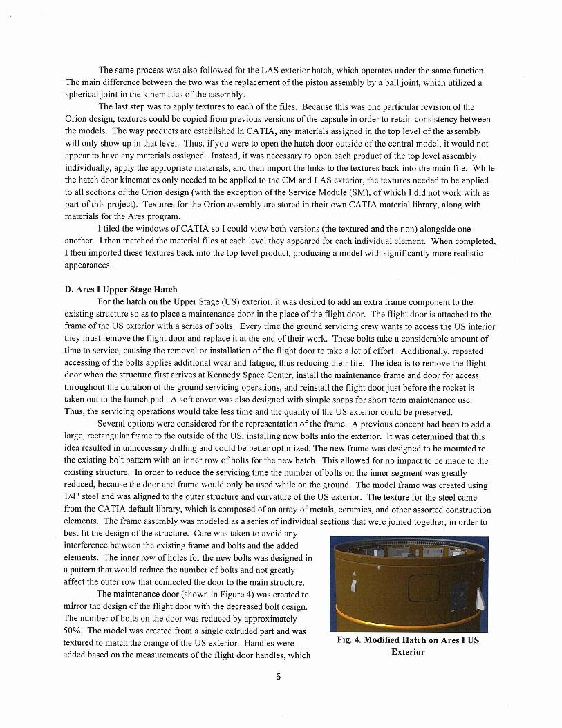
existing structure so as to place a maintenance door in the place of the flight door. The flight door is attached to theframe of the US exterior with a series of bolts. Every time the ground servicing crew wants to access the US interiorthey must remove the flight door and replace it at the end of their work. These bolts take a considerable amount oftime to service, causing the removal or installation of the flight door to take a lot of effort. Additionally, repeatedaccessing of the bolts applies additional wear and fatigue, thus reducing their life. The idea is to remove the flightdoor when the structure first arrives at Kennedy Space Center, install the maintenance frame and door for accessthroughout the duration of the ground servicing operations, and reinstall the flight door just before the rocket istaken out to the launch pad. A soft cover was also designed with simple snaps for short term maintenance use.Thus, the servicing operations would take less time and the quality of the US exterior could be preserved.
Several options were considered for the representation of the frame. A previous concept had been to add alarge, rectangular frame to the outside of the US, installing new bolts into the exterior. It was determined that thisidea resulted in unnecessary drilling and could be better optimized. The new frame was designed to be mounted tothe existing bolt pattern with an inner row of bolts for the new hatch. This allowed for no impact to be made to theexisting structure. In order to reduce the servicing time the number of bolts on the inner segment was greatlyreduced, because the door and frame would only be used while on the ground. The model frame was created using1/4" steel and was aligned to the outer structure and curvature of the US exterior. The texture for the steel camefrom the CATIA default library, which is composed of an array of metals, ceramics, and other assorted constructionelements. The frame assembly was modeled as a series of individual sections that were joined together, in order tobest fit the design of the structure. Care was taken to avoid anyinterference between the existing frame and bolts and the addedelements. The inner row of holes for the new bolts was designed ina pattern that would reduce the number of bolts and not greatlyaffect the outer row that connected the door to the main structure.
The maintenance door (shown in Figure 4) was created tomirror the design of the flight door with the decreased bolt design.The number of bolts on the door was reduced by approximately50%. The model was created from a single extruded part and wastextured to match the orange of the US exterior. Handles were Fig. 4. Modified Hatch on Ares I US
added based on the measurements of the flight door handles, which Exterior
6

were designed to be accessible on the servicing platforms. A soft cover was also modeled, as a solid piece using thesame inner section of the new frame. This cover would likely be applied using snaps attached to the maintenanceframe and would eventually be made of a flexible material.
This same design was also used for a similar hatch on the Ares I Inter-Stage (IS) model, with the onlynotable difference being that this particular hatch was set to match the white exterior of the IS. Each of thesecomponents can be hidden or shown at will, allowing the user to view different scenarios of the hatch assembly,which is then used in simulations of the various servicing processes. When completed, the products were saved tothe file for use in future demonstrations.
IV. Results and DiscussionA. MPPF High Bay South Wall
When completed, 106 additions were made to the south wall. The majority of these items were servicepanels that will house power supplies and other operational equipment. Each panel was individually detailed anddimensioned according to its description in the AutoCAD drawings and the ProE file. Additionally, several itemswere removed from the wall, such as valves and other connections that will not be necessary for the new program.Many of these items that were deemed possible to be used again in the future were simply hidden in the model, sothat they could be called back without the need of generating a new part.
While the outward facade of the modified wall appears cluttered, it will provide the appropriate interfacesand servicing supplies for the operations of the Orion program. Because of the large number of additions to thewall, many of the panels are within a marginal degree of one another. One of the purposes of modeling the wall inthis way is to analyze the positioning of these panels and ensure that once construction occurs none of theconnections will interfere with one another. The additions are detailed in Table 1 below. Listed are the quantities ofeach component that were added to the south wall of the High Bay. This includes the modification of the loweraccess door to a double door capable of the transfer of larger hardware. However, it does not take into account thespecific items that were removed from the wall - these components were minimal as compared to the componentsthat remained in the new model of the High Bay. Instead, the table highlights the large array of components thatwill be necessary for Orion ground support operations.
Table 1. MPPF High Bay South Wall Modifications.Z3 Doors (including modified double door) 4 Power Cabinets1 Cable Tray 3 Potable Water (PW) Supplies1 Fire Alarm (FA) 2 Control Electronics System (CES) Panels4 Phone Outlets 7 Gaseous Nitrogen (GN2) Supplies2 Graphics Processing Units (GPU) 3 Ground Cooling System (GCS) Panels3 Test and Operations (TO) Panels 3 Ground Special Power (GSP) Supplies3 Communications (COMM) Panels 3 O erational Television (OTV) Cameras2 Kennedy Ground Control System (KGCS) Racks 4 Switches3 KGCS Panels 3 Hy er of Vent Interface Panels (HVIP)3 Exit Signs 14 Power Supplies2 Power Conduits 7 Ground Operations Processing (GOP) Panels5 Environmental Control Systems (ECS) Ducts 5 OTV Panels1 Hose Reel 3 Breathing Air (BA) Units2 Ground Plates 5 Timin and Countdown (TCD) Interfaces
Many of the connection points are intended for use by the Orion Crew Exploration Vehicle (CEV) servicestands that will be constructed in the High Bay. The CEV is composed of the Command Module (CM) and theService Module (SM). The service stands are designed with a platform for each level of access to the CEV. Theupper doors on the wall of the High Bay reflect the egress points from the platforms. Egress stairs will be built from
2 Acronyms: NASA Scientific and Technical Information (STI)
7

those doors to the outside of the building in the case of any emergency procedures. The panels and interfaces aredesigned to accommodate the needs of the service stands.
When the south wall (shown before and after modification in Figure 5) is combined with its five associatedwalls (ceiling and floor included), a model is produced of the entire MPPF High Bay. This is a crucial element inplanning the operations of this facility, as any equipment that will be brought in can be analyzed in either CATIA orDELMIA so as to determine the optimal positioning of the components and connection points. Any clearances canalso be tested ahead of time, so that there are no surprises when the actual components are placed in the High Bay.Even the ceiling with its lighting construct has been modeled in CATIA, allowing for a realistic view of the workspace and accurate renderings of the room to be produced.
DELMIA allows the user to show the customer each step of a process via simulations and HD video files.For example, a simulation can demonstrate the transport of the Orion CEV into the MPPF, its installation into theservice stands, and any procedures that will be followed in the servicing of the capsule (i.e. a hatch being opened foraccess by technicians). The simulation often includes modeled technicians that are created using the CATIAErgonomics Design & Analysis Human Builder, which allows the user to place the body into any position necessary(ex. a kneeling technician vs. one reaching for an object). These modeled technicians are a valuable resource indetermining the accessibility of the design, and thus affect the overall structure of both the process and the modelitself. The tools in CATIA allow the user to explore avariety of options, testing clearances and measurementsalong with analyzing the general efficiency of the process,long before any of the steps are put into action. Duringmeetings with the customers, the simulation is shown anddirected by the people who model them, while thecustomers have the opportunity to express any concerns orchanges based on the new data. This instantaneousfeedback allows for open discussion of the best practicesfor the facility and a forum for determining new analysesthat will aid in the design of the new operations.
saw
Fig. 5. MPPF High Bay South Wall Beforeaccounted for in the digital representation. Its purpose, Modification (Top) and After (Bottom)along with that of the MPPF model, is to optimize thefacility's utilization of space. The drawings produced by the Design Vis software are used, as well, as a tool forinteractively presenting the layout for discussion. The difference is that while the particular MPPF model describedpreviously is focused on future modifications, the model of the SSPF is based off of current properties andequipment. Additionally, the model of the SSPF is not entirely three-dimensional as the MPPF was, in that only thefloor of the room is modeled, although the components placed there are in 3D.
The model (and the associated drawings) indicate the most up-to-date locations of all the equipment presentin both the SSPF High Bay and the I-Bay. When the drawings of each individual footprint are produced they areshown at a weekly meeting in which the facility owners discuss plans for the building. The drawings allow theowners to note open spaces for any potential equipment or operations. They also provide a view of the spacerequirements for each existing operation. While in the past the hardware moved considerably more often due to theheight of the assembly of the International Space Station (ISS), the current day-to-day operations are still motiveenough to continue mapping the facility for process and usage optimization, as well as future facility use.
The Design Vis software that is used to generate these drawings is considerably outdated by traditionalstandards of display and user compatibility, yet it serves its function with simplicity and an interface tailored to thespecific needs of the facility updating process. The component library is a valuable resource for retainingconsistency, both within the models and between different facilities on site. For example, a ground plate that is used
B. SSPF MappingThe model of the SSPF is similar to the model of
the MPPF in that each piece of hardware in the facility is
8
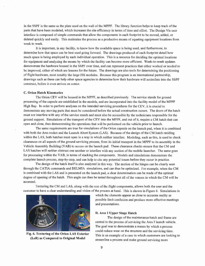
Fig. 6. Texturing of the Orion LAS Exterior(Left) as Compared to Original Model
in the SSPF is the same as the plate used on the wall of the MPPF. The library function helps to keep track of theparts that have been modeled, which increases the site efficiency in terms of time and effort. The Design Vis userinterface is composed of simple commands that allow the components in each footprint to be moved, added, ordeleted quickly and easily. This maintains the process as a productive means of equating equipment locations fromweek to week.
It is important, in any facility, to know how the available space is being used, and furthermore, todetermine how that space can be best used going forward. The drawings produced of each footprint detail howmuch space is being employed by each individual operation. This is a resource for deciding the optimal locationsfor equipment and analyzing the means by which the facility can become more efficient. Week-to-week updatesdemonstrate the hardware housed in the SSPF over time, and can represent practices that either worked or needed tobe improved, either of which are lessons for the future. The drawings are also tools for determining the positioningof flight hardware, most notably the large ISS modules. Because this program is an international partnership,drawings such as these can help other space agencies to determine how their hardware will assimilate into the SSPFconstruct, before it even ar rives on center.
C. Orion Hatch Kinematics
The Orion CEV will be housed in the MPPF, as described previously. The service stands for groundprocessing of the capsule are established in the models, and are incorporated into the facility model of the MPPFHigh Bay. In order to perform analyses on the intended servicing procedures for the CEV, it is crucial todemonstrate any moving parts that must be considered before the actual construction occurs. The doors of the hatchmust not interfere with any of the service stands and must also be accessible by the technicians responsible for theground support. Simulations of the transport of the CEV into the MPPF, and out of it, require a CM hatch that canopen and close, thus demonstrating the operations that will be performed on the vehicle prior to launch.
The same requirements are true for simulations of the Orion capsule on the launch pad, when it is combinedwith both the Ares rocket and the Launch Abort System (LAS). Because of the design of the CM hatch residingwithin the LAS, both hatches must open in a way in which neither interfere. Modeling, such as this, is used to checkclearances on all aspects of the ground servicing process, from its initial transport in the MPPF to its assembly in theVehicle Assembly Building (VAB) to access on the launch pad. These clearance checks ensure that the CM andLAS hatches will neither obstruct one another or interfere with any section of the mobile launcher. The same goesfor processing within the VAB, in terms of stacking the components. Models and simulations demonstrate thecomplete launch process, step-by-step, and can help to cite any potential issues before they occur in practice.
The design of the hatch itself is also analyzed in this way. The motion of the hinges can be clearly seenthrough the CATIA commands and DELMIA simulations, and can thus be optimized. For example, when the CMis combined with the LAS and is presented on the launch pad, a clear determination can be made of the optimaldegree of opening of the hatch. This angle can then be tested throughout all of the venues in which the CM will beaccessed.
Texturing the CM and LAS, along with the rest of the flight components, allows both the user and thecustomer to have a clear understanding and vision of the process at hand. This is shown in Figure 6. Simulations in
which the elements appear as close to accurate reality as• possible limit confusion and produce more effective meetings
and presentations.
D. Ares I Upper Stage HatchThe design of the maintenance hatch and frame are
central to the process of servicing the Ares I launch vehicle.The goal was to demonstrate a means by which a processcould reduce wear on the structure and the servicing time.This is an example of a case in which customers are looking tostreamline a process and make ground servicing more
9

efficient. Both hatches, one located on the Upper Stage and one located on the Inter-Stage, are designed to beaccessible by technicians while the vehicle is being supported in the VAB. This determination was made based onthe access measurements of the modeled technicians using the respective CATIA workbench. As with the hatchdoors of the Orion capsule, the design of the modified frame and door assembly was monitored for any interferencesbetween the existing structure and the addition.
Simulations in DELMIA will show the step-by-step process, in which the initial transport with the originalflight door will be shown as the vehicle is brought into the VAB. The flight door will then be removed, or hidden inthe model, and replaced by the installation of the maintenance frame and door. Throughout the servicing processesrepresented by DELMIA the maintenance hatch and the soft cover can be interchanged depending on the needs ofthe operation. In order to show the vehicle as flight-ready, the maintenance section can be hidden in all depictionsand the flight door can be reinstated.
As with the other models, the textures applied to the model create a realistic view of the structure. Theclear vision of the process allows for an open forum for discussion, in which everyone is on the same page in termsof the presentation based on the given data. In this way the customer can determine the next step in the designprocess and evaluate whether or not the model demonstrates a component that satisfies all assigned needs.
V. ConclusionsThe key to future operations on site is to optimize the resources we have now and design processes that will
be efficient and productive. It is essential to the design process to have a means of presenting and representing thecustomers' ideas in a way that can be quickly modified and incorporated into the overall model. In the case of theMPPF High Bay, this is reflective of the preparations being made for the next generation of space vehicle andassociated ground operations. The design of the Orion CEV will affect how the facilities which with it operates willbe designed, along with the access requirements of the Ares vehicle. For the SSPF, this is an example of optimizingthe current operations and preparing for both the immediate and long-term future needs. Modeling and simulatingthese facilities and hardware will help Kennedy Space Center to streamline their ground support processes andprepare for new programs in the future.
AcknowledgmentsJ.L. Marshall would like to thank her mentor, Kristin Lucas, along with Robert Edwards, Bob Humeniuk,
and the rest of the Boeing DVG team.
References2Heimerl, Lynn. Acronym Listing. NASA Scientific and Technical Information (STI). NASA Center for AeroSpace Information(CASI). http://www.sti.nasa.aov/nasaonly/acronym/main.html . [cited 28 July 2010].
10