APPLICATIONS OF MO METAL AND - China Tungsten · APPLICATIONS OF MO METAL AND ITS ALLOYS WRITTEN...
16
M APPLICATIONS OF MO METAL AND ITS ALLOYS WRITTEN FOR IMOA BY DR. JOHN SHIELDS, JR, FAFM, OF CLIMAX SPECIALTY METALS CLEVELAND, OHIO (1995) O I A © INTERNATIONAL MOLYBDENUM ASSOCIATION
Transcript of APPLICATIONS OF MO METAL AND - China Tungsten · APPLICATIONS OF MO METAL AND ITS ALLOYS WRITTEN...

M
A P P L I C AT I O N S O FM O M E T A L A N D
I T S A L L O Y S
WRITTEN FOR IMOA BY DR. JOHN SHIELDS, JR, FAFM, OFCLIMAX SPECIALTY METALS CLEVELAND, OHIO (1995)
OIII AAA
© INTERNATIONAL MOLYBDENUM ASSOCIATION
2
Molybdenum metal and its alloys are used in a varietyof markets including electrical and electronic devices,materials processing, glass manufacturing, hightemperature furnaces and equipment, and aerospace &defense applications. The properties that makemolybdenum metal and its alloys the materials of choicein these markets include thermal and electricalconductivity, thermal expansion, high-temperaturestrength, vapor pressure, environmental stability, andresistance to abrasion and wear. This report attemptsto provide the reader with an understanding of just whythis unique material is used in its many applications. Ashort primer on techniques for fabricating and workingwith molybdenum follows the applications discussion.
This market is probably the largest for molybdenum andits alloys. It includes applications such as mandrel wirefor manufacturing lamp filaments, wire leads andsupport structures for lighting and electronic tubemanufacture, powders for specially formulated circuitinks and the tooling used to apply them to multi-layercircuit boards, internal components for microwavedevices, high-performance electronic packaging, and
heat sinks for solid state power devices. A subset of thismarket is comprised of electrical and electronicequipment used in the medical industry. Many of theinternal components of X-ray tubes, from the targetitself to support structures and heat shields, aremanufactured from molybdenum and molybdenummetal alloys. Molybdenum also finds its way into X-raydetectors, where sheet with precisely controlled gauge isused.
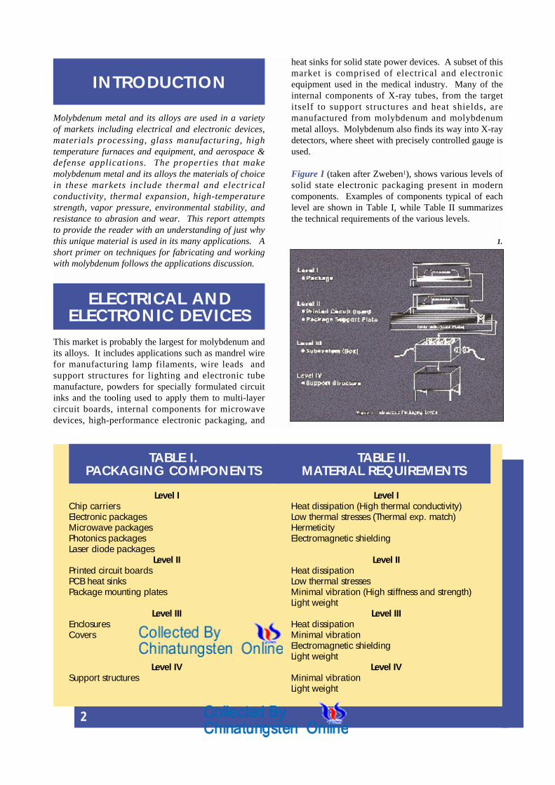
Figure I (taken after Zweben1), shows various levels ofsolid state electronic packaging present in moderncomponents. Examples of components typical of eachlevel are shown in Table I, while Table II summarizesthe technical requirements of the various levels.
INTRODUCTION
ELECTRICAL ANDELECTRONIC DEVICES
TABLE II.MATERIAL REQUIREMENTS
Level I Level IChip carriers Heat dissipation (High thermal conductivity)Electronic packages Low thermal stresses (Thermal exp. match)Microwave packages HermeticityPhotonics packages Electromagnetic shieldingLaser diode packages
Level II Level IIPrinted circuit boards Heat dissipationPCB heat sinks Low thermal stressesPackage mounting plates Minimal vibration (High stiffness and strength)
Light weightLevel III Level III
Enclosures Heat dissipationCovers Minimal vibration
Electromagnetic shieldingLight weight
Level IV Level IVSupport structures Minimal vibration
Light weight
TABLE I.PACKAGING COMPONENTS
1.

3
Molybdenum is typically used in Level I and IIcomponents, where thermal expansion matching,thermal conductivity, and to a lesser extent stiffness, areimportant issues. Table III lists some physicalproperties of a variety of materials commonly used inelectronic packaging. The first group is devicematerials, whose properties and performancecharacteristics drive the selection of other materials inelectronic packages. The second group of materialsconsists of non-metallic substrates and circuit boardmaterials. The third group contains several metals incommon use for electronic packages.
The heat created by the device must be removed to
ensure reliable operation. In addition, the thermalexpansion created by the heating must be preventedfrom causing excessive stresses that could develop frommismatches between packaging materials. In militarydevices, minimum weight and high stiffness are addedrequirements. The advantages conferred bymolybdenum and molybdenum-containing compositessuch as Cu/Mo/Cu are clearly shown in the table. Thelast two columns are specific properties, normalized bythe specific gravity (r/r H2O) of each material. Thehigh modulus and conductivity of molybdenum more than compensate for its density, with the resultthat it still enjoys significant advantage in specificproperties.
TABLE III.PHYSICAL PROPERTIES OF ELECTRONIC PACKAGING MATERIALS
Material CTE, 10-6 K-1 k, W/m.K E, GPa r, g/cm3 kspec., W/m.K Espec., GPa
Si 4.1 135 113 2.3 59 0
GaAs 5.8 39 85 5.3 7 0
Al2O3 6.5 20 380 3.9 5 97
BeO 6.7 250 330 2.9 86 114
AlN 4.5 250 330 3.2 78 103
Epoxy 60 0.3 3 1.2 0 3
Al (1100) 23 221 69 2.7 82 26
Cu 17 400 117 8.9 45 13
Mo 5 140 324 10.2 14 32
Kovar® 5.9 17 131 8.3 2 16
Cu/Invar®/Cu 5.2 176* 138 8.4 21* 16(20/60/20) 53** 6**
Cu/Mo/Cu 5.7 208* 269 10.0 21* 27(13/74/13) 170** 17**
Cu/Mo/Cu 8.6 311* 186 9.7 32* 19(33/33/33) 251** 26**
Mo 15 Cu 7.0 160 280 10.01 16 28
Mo 30 Cu 7.5* 176* 240* 9.64 18* 25*
W 10 Cu 6.5 180 330 17.0 11 19
*In-plane **Through-thickness
(infiltrated powdercomposite)
(rolled powdercomposite)
(infiltrated powdercomposite)

4
Molybdenum finds application as a buffer between therelatively low-expansion materials used in integratedcircuit (IC) packages and the copper normally used tosupply electrical power to the devices and to removeheat from them as well. It is even finding application asa replacement for the silicon substrates used in somedevices. Figure 2 illustrates a multichip moduleapplication where molybdenum has displaced silicon asthe device substrate. This particular application usesthin film technology to apply the various layers whichmake up the device. Power rectifiers use largequantities of molybdenum sheet that is stamped andplated with nickel, copper, or rhodium to provide boththermal expansion control and heat management. Thesedevices find application in diesel-electric and electricrailroad engines and industrial motor power suppliesand controls. Pressed and sintered heat sinks for smallelectrical devices (Figure 3) are ubiquitous in theconsumer goods arena.
Cladding molybdenum with copper results in a material(Cu/Mo/Cu, or CMC)whose properties can be tailoredto the application at hand. Figure 4 illustrates the effectof copper cladding thickness on thermal conductivity ofCMC. The copper also increases the thermal expansioncoefficient of the composite as illustrated in Figure 5,allowing a good match with ceramic substrate materialssuch as alumina (Al2O3) and beryllia (BeO). Figure 6illustrates a CMC application in military electronics.The high-density surface mount avionics board shownin the figure employs a CMC constraining core tomodify the expansion of the epoxy resin board so that itis compatible with the alumina chip carriers that aremounted directly on the board. The ability to employsurface mounting allows designers to employ higherdensity circuitry and reduce the overall volume of thecomponents. CMC brings the added benefit of highelastic modulus to the assembly, resulting in reducedsusceptibility to vibration-induced failures.
Several groups have also worked on molybdenum-copper analogues to the tungsten-copper powdercomposites that have been long available2,3. Thesematerials are available commercially in variouscompositions and shapes. Powder composites offer thepotential advantage of isotropic properties and lesshysteresis in thermal expansion, probably due to thegreater triaxiality of the internal stress distribution1.They also offer greater flexibility in tailoring thermalproperties because varying powder blends issignificantly less cumbersome than manufacturingdifferent cladding ratios on rolled sheet.
THERMAL CONDUCTIVITY OFCu-CLAD MoAverage Between -40C and 100C
In plane Throughthickness
350.0
300.0
250.0
200.0
150.0
100.0
50.0
0.00 5 10 15 20 25 30 35
% Cu per side
TC, W/m*K
CTE OF Cu-CLAD MoAverage Between -55C and 125C
1.0E-05
8.0E-06
6.0E-06
4.0E-06
2.0E-06
0.0E+000 5 10 15 20 25 30 35
% Cu per side
CTE,1/K
2.
3.
4.
5.
6.

5
Hot Work ToolingHigh-temperature strength and resistance to deformationplay an important role in this segment. Aerospaceforgers employ tooling made of molybdenum alloys toforge engine materials at high temperature. Extrusionhouses have found molybdenum alloys to be ideal forcertain applications in the brass industry. Molybdenum -tungsten alloys are used in the handling of molten zinc,due to their chemical compatibility with that material.The processing of many electronic components, whetherit be by sintering the ceramic material used in high-
performance circuit boards or the metallization ofsilicon wafers, requires molybdenum metal components.
Table IV lists a variety of molybdenum alloycompositions that are commercially available, alongwith the approximate one-hour recrystallizationtemperature for the alloy. The precise recrystallizationtemperature will depend also upon the manufacturinghistory of the particular product form being considered(a large forging with 60-65% reduction will recrystallizeat a higher temperature than wire with 99.9%+reduction in cross-section). There are three broadclasses of molybdenum alloys: those strengthened byreactive metal carbides, those strengthened bysubstitutional elements, and those stabilized by amechanically dispersed second phase. Alloys designedto take advantage of a combination of these differentapproaches also can be found.
MATERIALSPROCESSING
TABLE IV.COMMERCIALLY AVAILABLE MOLYBDENUM ALLOYS
Alloy Nominal Composition, Wt. % TRecryst., C
Pure Mo 100 Mo 1100
Carbide-Strengthened
TZM 0.5 Ti, 0.08 Zr, 0.03 C 1400
TZC 1.2 Ti, 0.3 Zr, 0.1 C 1550
MHC 1.2 Hf, 0.05 C 1550
ZHM 0.4 Zr, 1.2 Hf, 0.12 C 1550
HWM-25 (Combination) 25 W, 1.0 Hf, 0.07 C 1650
Substitutional
25 W 25 W 1200
30 W 30 W 1200
5 Re 5 Re 1200
41 Re 41 Re 1300
50 Re 47.5 Re 1300
Dispersed-Phase
PSZ 0.5 vol % ZrO2 1250
MH 150 ppm K, 300 ppm Si 1800
KW 200 ppm K, 300 ppm Si, 100 ppm AL 1800
MLR 0.7 La2O3 1800
MY 0.55 yttrium mixed oxide 1300

6
The carbide-strengthened alloys are normally employedwhere high-temperature strength is required. Figure 7is a composite plot of the strength of several of thesealloys as a function of test temperature4, with a similarplot for pure molybdenum. The scatter bands on thefigure were derived from a variety of points determinedfor samples having differing processing histories, andare typical of the range of properties available incommercially available materials.
The high strength at elevated temperatures combinedwith high thermal diffusivity inherent in molybdenummake the carbide-strengthened alloys attractive for hot-work tooling applications. Figure 8 illustrates the useof TZM tolling in the Gatorizing®, or isothermalforging, process used to forge superalloy engine discs.In this process, the tooling and workpiece are both
heated to the forging temperature, and the disc is formedsuperplastically. The entire tooling stack and workpieceare contained in a vacuum chamber, in order to avoidformation of volatile oxides of molybdenum. Thistechnique is capable of producing highly defined discforgings that require much less machining than thoseproduced by conventional techniques. This practice hasproduced integrally bladed discs on an experimental basis.
These alloys also find application in conventional hotwork tooling as well. A primary reason for this is theirresistance to thermal shock and cracking. One way toillustrate the advantage inherent in molybdenum in suchapplications is by the use of a parameter developed forthermal fatigue. The thermal fatigue resistanceparameter is given by:
P = s y x kE x CTE
where sy = Yield Strengthk = Thermal ConductivityE = Elastic ModulusCTE = Coefficient of Thermal Expansion
High yield strength (resistance to plastic deformation)and thermal conductivity (dissipation of thermalgradients and stresses), or low modulus and coefficientof thermal expansion (both related to the degree ofthermal stress developed), give high values for P (adesirable result). Table V summarizes the values of Pobtained for iron-base, nickel-base, and molybdenumtooling materials using room temperature values for theformula’s components. While the steel has a distinctadvantage in strength, and both the steel and nickelalloys have advantage in modulus, the high thermalconductivity and low coefficient of expansion formolybdenum make it the preferred material for thermalshock applications. TZM and MHC alloys both findapplication in the extrusion of copper and copper alloys.The die design requirements are somewhat differentfrom those normally used by tool designers, primarilybecause of molybdenum’s low coefficient of thermalexpansion. Significantly more shrink fit is required formolybdenum than for steel or nickel alloy dies in nickelalloy cases, so that the die does not loosen as theassembly heats up to its normal operating temperature.Once this is accounted for, the molybdenum diesperform very well.
1200
1000
800
600
400
200
400 200016001200800
TZC, MHC
Mo
Test temperature,°C
Ten
sile
str
engt
h, M
Pa
TZM
TABLE V. VALUES OF THETHERMAL FATIGUE PARAMETER FOR SEVERAL MATERIALS
Material sy, MPa k, W/m.K E, GPa CTE, 10-6
C-1
PH-13 1227 28 215 12 .013Ni-base 500 10-20 200 10-12 .002-.005Mo 620 140 324 5 .054
7.
8.

7
Molten Metal ProcessingAluminum die casters use molybdenum to solve thermalchecking and cracking problems that otherwise cannotbe eliminated. In this case, TZM inserts, cores and pinsare used in areas prone to hot checking. Molybdenum’scost makes the cost of tooling quite high in comparisonto steel if the entire tool is manufactured from moly.Rapid solidification equipment using rotating disc androtating drum technology benefits from the use of TZMand MHC alloys. Here again, the high-temperaturestrength of these materials and their resistance tothermal shock failures permits the processing of highermelting point materials by this technique than would beotherwise possible. Figure 9 illustrates this applicationin the melting of highly reactive metal powders.Another unique application for molybdenum alloys is inthe handling of molten zinc. At one point in time,tungsten was thought to be the only material resistant tocorrosion by molten zinc. Alloying molybdenum withtungsten resulted in an equally resistant material at agreatly reduced cost. The Mo-25% and Mo-30%tungsten alloys evolved from this work, and are widelyused for impellers, pump components, and piping thathandle molten zinc.
Thermal Spray ProcessingA significant amount of molybdenum powder isconsumed by thermal spray applications. In thistechnology, molybdenum metal powder is blended withbinders rich in chromium and nickel, then plasma-sprayed on piston rings and other moving parts wherewear is a critical performance issue. The older wirespray process still accounts for the majority ofmolybdenum consumed in the market. In both cases,
the material to be sprayed is fed through a hightemperature gas jet. This jet may be generated by aplasma torch or a high velocity gas torch. The feedmaterial is melted in the flame, and droplets are carriedby the jet to the surface of a substrate, where they impactthe surface and freeze rapidly5. With time, a coating isbuilt up on the substrate’s surface. Composite or gradedcoatings can be produced by controlling the compositionof the feed material to the jet.
Piston rings (Figure 10) are coated with puremolybdenum, or alloy powder blends. The paper andpulp industry also employs the coatings for wear andcorrosion resistance. A variety of compositions ispossible by blending with other powder components.The most common alloy blends contain varying amountsof Ni, Cr, B, and Si. The powders used in sprayapplications are markedly different from those used to
10.
9.
8
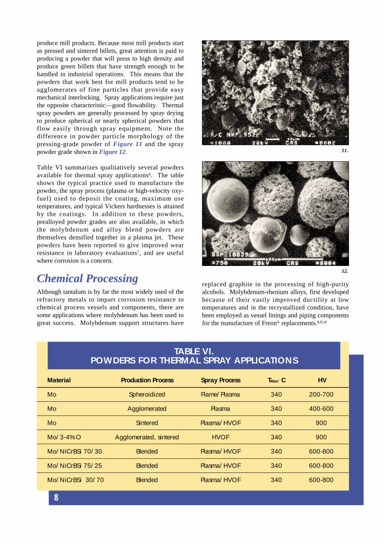
produce mill products. Because most mill products startas pressed and sintered billets, great attention is paid toproducing a powder that will press to high density andproduce green billets that have strength enough to behandled in industrial operations. This means that thepowders that work best for mill products tend to beagglomerates of fine particles that provide easymechanical interlocking. Spray applications require justthe opposite characteristic—good flowability. Thermalspray powders are generally processed by spray dryingto produce spherical or nearly spherical powders thatflow easily through spray equipment. Note thedifference in powder particle morphology of thepressing-grade powder of Figure 11 and the spraypowder grade shown in Figure 12.
Table VI summarizes qualitatively several powdersavailable for thermal spray applications6. The tableshows the typical practice used to manufacture thepowder, the spray process (plasma or high-velocity oxy-fuel) used to deposit the coating, maximum usetemperatures, and typical Vickers hardnesses is attainedby the coatings. In addition to these powders,prealloyed powder grades are also available, in whichthe molybdenum and alloy blend powders arethemselves densified together in a plasma jet. Thesepowders have been reported to give improved wearresistance in laboratory evaluations7, and are usefulwhere corrosion is a concern.
Chemical ProcessingAlthough tantalum is by far the most widely used of therefractory metals to impart corrosion resistance tochemical process vessels and components, there aresome applications where molybdenum has been used togreat success. Molybdenum support structures have
TABLE VI.POWDERS FOR THERMAL SPRAY APPLICATIONS
Material Production Process Spray Process TMax’ C HV
Mo Spheroidized Flame/Plasma 340 200-700
Mo Agglomerated Plasma 340 400-600
Mo Sintered Plasma/HVOF 340 900
Mo/3-4% O Agglomerated, sintered HVOF 340 900
Mo/NiCrBSi 70/30 Blended Plasma/HVOF 340 600-800
Mo/NiCrBSi 75/25 Blended Plasma/HVOF 340 600-800
Mo/NiCrBSi 30/70 Blended Plasma/HVOF 340 600-800
replaced graphite in the processing of high-purityalcohols. Molybdenum-rhenium alloys, first developedbecause of their vastly improved ductility at lowtemperatures and in the recrystallized condition, havebeen employed as vessel linings and piping componentsfor the manufacture of Freon® replacements.8,9,10
11.
12.

9
Because of its compatibility with many molten glasscompositions, molybdenum has found application inhandling equipment, tooling, and furnace construction.The most common use for molybdenum is as electrodesfor the melting of glass. Because glasses are electricallyconductive when molten, molybdenum electrodes canbe used to increase the energy input in conventionallyfired furnaces and thereby increase the throughput of thefurnaces. There are as many electrode designs as thereare design firms, but all immerse the molybdenumelectrode into the furnace where it is protected fromoxidation by the glass itself. Figure 13 illustrates acommon type of design, wherein the electrodes areintroduced through the side of the glass furnace11. Thisnecessitates protection of the portion of the electrodeexposed to the atmosphere from oxidation. This can bedone by internal or external cooling by the use ofprotective atmospheres or by protective coatings basedon molybdenum silicides12. The advantage of thisdesign is that, as the electrode wears in the furnace, itcan be replaced by adding on to its external end, and
pushing the newly extended electrode into the bath.
Molybdenum is not the only potential electrodematerial. Table VII summarizes the advantages anddisadvantages of several materials that are in use orhave been in used in the past. Molybdenum'sadvantages in creep resistance, glass compatibility, andresistance to thermal shock all outweigh the increasedcost with respect to most of the other materials.
GLASSMANUFACTURING
TABLE VII.GLASS MELTING ELECTRODE MATERIALS
Advantages Disadvantages Advantages Disadvantages
Molybdenum Inconel 600
High current density Oxidation Corrosion resistant 1200 C maximum
Excellent strength Incompatible with lead glass Moderate cost Low strength above 1200 C
Thermal shock Moderately high Moderate strength Poor sag resistanceresistance material cost
1700 C capability
Excellent total cost
Carbon Platinum
Very low cost Requires reducing conditions Extraordinarily stable Extremely expensive
2000 C capability Low current densities 1400 C capability Poor in reducing conditions
Bubble formation High frequencies (10 khz)
Iron Tin Oxide
Low cost Colors glass No coloration Oxidation
Oxidation 1350 C capability Low shock resistance
13.

10
Molybdenum’s strength and stability at elevatedtemperature make it an attractive material forconstruction of high-temperature furnaces and thefixtures and tooling associated with them. Figure 14shows the vapor pressure of molybdenum as a functionof temperature13. Molybdenum’s high melting pointmeans that at typical operating temperatures for vacuumfurnaces, volatilization of internal components madefrom molybdenum or molybdenum alloys will benegligible. Figure 15 illustrates an all-metal hot zoneemployed in a modern vacuum furnace. Metal hotzones offer the utmost in vacuum cleanliness for thoseheat treating applications that cannot tolerate carbon oroxygen contamination. (Titanium, niobium, andtantalum are all metals that require environments free ofoxygen and carbon.) The increasing use of hot isostaticpressing (HIP) to consolidate powder materials andimprove the integrity of cast metals has also boosted theneed for molybdenum products. Molybdenum and itsalloys are widely used as materials of construction forHIP vessels, being found in their heating elements,mantles, and support structures .
The ceramic processing industry also makes extensiveuse of molybdenum components for fixtures andsintering boats. Molybdenum and its alloys are thematerials of choice for sintering ceramic nuclear fuels,while the oxide ceramics processed by the electronicsindustry are nearly universally sintered in hydrogen onmolybdenum carriers.
In these applications, the long-term mechanical stabilityof components is important. Figure 16 shows thestress-rupture behavior of molybdenum and the carbide-strengthened alloys4. The strength advantage andresistance to recrystallization conferred to these alloys isreflected in their greater creep resistance at moderatetemperatures (<1500 C). Above these temperatures,especially for longer times, the microstructures of thesematerials recrystallize and they lose their strength. Forapplications requiring creep resistance at 1500 C andabove, the dispersion-strengthened alloys are superior.Figure 17 illustrates this in a dramatic way, showing thecreep rates measured on pure molybdenum,potassium/silicon doped molybdenum, and lanthanum-doped molybdenum at 1800 C14. Note that the scale islogarithmic, and not linear. The doped alloys areseveral orders of magnitude better than puremolybdenum under these conditions. These materialsare typically employed in applications such as sinteringboats and trays for nuclear fuels and ceramics.
HIGH-TEMPERATUREFURNACES AND
EQUIPMENT
VAPOR PRESSURE OF MOLYBDENUM METAL
1.0E+031.0E+03
1.0E+021.0E+02
1.0E+011.0E+01
1.0E+001.0E+00
1.0E-011.0E-01
1.0E-021.0E-02
1.0E-031.0E-03
1.0E-041.0E-04
1.0E-051.0E-05
1.0E-061.0E-06
1.0E-071.0E-071,000,000 2,0002,000 3,0003,000 4,0004,000 5,0005,000 6,0006,000
Temperature, CTemperature, C
Vapor pressure, torrVapor pressure, torr
Typical vacuum furnace limitTypical vacuum furnace limit
14.
15.
16.
17.
11
Compatibility with hot gases and strength attemperature are the typical properties that result inmolybdenum being used in this market area.Molybdenum’s poor oxidation resistance prevents itfrom being used in a wider variety of applications thatcould use its high strength, but in rocket and reactivegas valves, where high performance is required for arelatively short time, it finds application. For certain ofthese components, the metal injection molding processis being developed because of its potential forsignificant material and machining savings.Molybdenum is also being employed in munitionsapplications, a relatively new application.
Molybdenum alloys, like all materials, are seldom usedin their applications as they are produced by the mill orthe raw materials manufacturer. They must be formed,joined to other components, machined, and otherwisechanged into an engineered component. This sectionbriefly summarizes a few of the more important pointsregarding the use of these materials in manufacturedcomponents.
MachiningMolybdenum metal and its alloys are machinable by allthe common metal removal processes. Many shopsaround the world have manufactured a wide variety ofparts in a range of sizes from all the molybdenumalloys The materials are capable of being machinedwith excellent surface finishes and to exactingtolerances.
Several points must be borne in mind when preparing tomachine molybdenum or any of its alloys. Whilemolybdenum retains its strength to high temperatures, itis not particularly strong at ambient temperatures.Neither is its ductility as great as carbon steel or brass.Furthermore, its (relatively speaking) high ductile-brittletransition temperature means that it is susceptible tostress risers and other geometric features that mightinitiate cracks.
Machines should be rigid and free from backlash, andwork should be securely clamped. Close attention
should be paid to tool sharpness. Dull tools can tear thematerial instead of cutting it cleanly, and createmicrocracks that limit the life of the component beingmachined. High speed tools are generally adequate, aslong as they are kept sharp. Carbide grades performwell, particularly where problems arise due to theabrasiveness of chips and dust. The tendency formolybdenum to form discontinuous chips and abrasivedust is one reason why inexperienced shops sometimesare over-optimistic about their ability to machine thesematerials economically. Carbide tools also prove theireconomic worth in jobs where long uninterrupted cutsare required, due to their better life between regrinds.
Much heavy machining, such as ingot scalping andrough turning, is accomplished without lubrication. Forbest finishing work, lubrication flushes dust away fromthe tool/workpiece interface and provides cooling aswell. Chlorinated solvents were once the coolant ofchoice for fine finish machining of molybdenum and itsalloys, but environmental and health concerns with theuse of such coolants has reduced their use to near zerolevels.
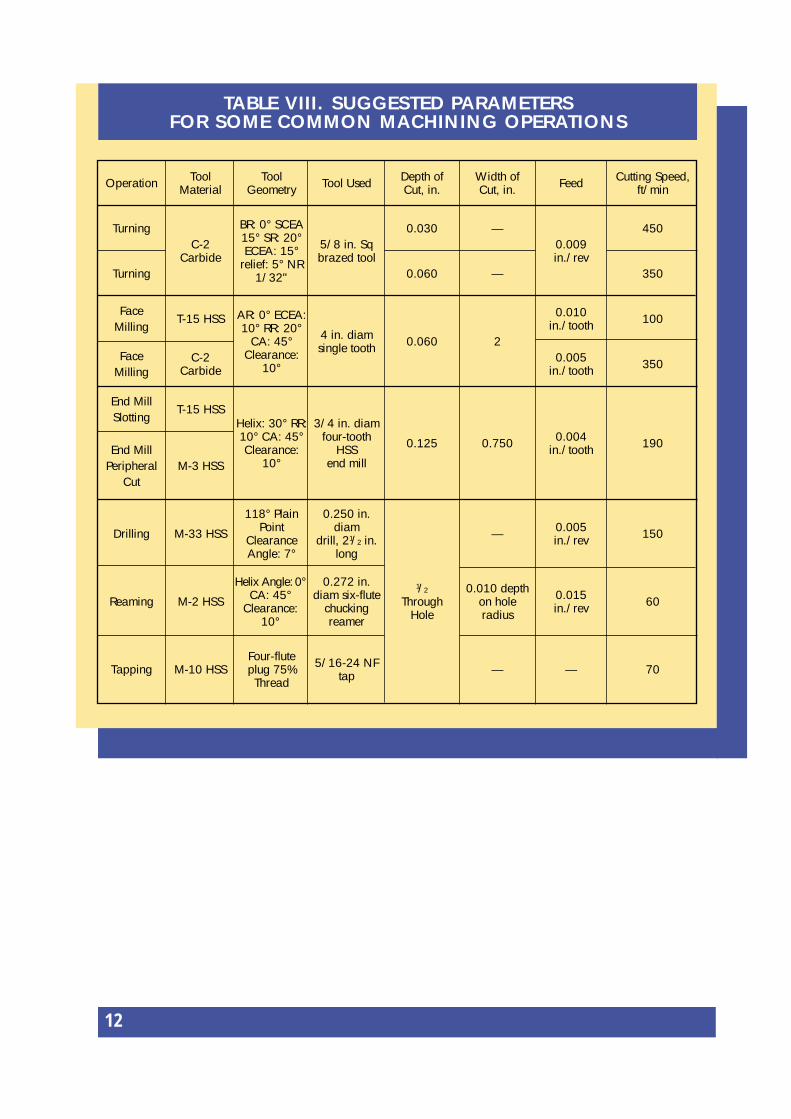
Table VIII (see over page) summarizes the results of anextensive research program funded by the U. S AirForce into the appropriate techniques for machiningmolybdenum and its alloys15. The parameters in thetable are a good starting point for machining thesematerials. Experimentation on any specific job willallow a shop to optimize their procedures and minimizetheir manufacturing cost.
Other machining processes such as grinding, photo-etching, and electrical discharge machining are alsocommonly performed on molybdenum and its alloys.Care must be exercised when EDMing molybdenumand its alloys because the surface zone frequentlycontains a recast layer. This structure is susceptible tomicrocracking and should be removed by mechanical orchemical polishing prior to placing the part in service.Grinding also has the potential to cause overheating andsurface cracking in these materials if sufficient amountsof coolant are not employed. Manufacturers of grindingwheels and abrasives have a variety of wheelcompositions that are designed to be employed for arange of applications. They can be a valuable source ofinformation and technical assistance in choosing wheelcompositions and grinding practices.
AEROSPACE ANDDEFENCE
APPLICATIONS
MANUFACTURINGCONSIDERATIONS
12
TABLE VII I . SUGGESTED PARAMETERSFOR SOME COMMON MACHINING OPERATIONS
Operation ToolMaterial
Tool Geometry Tool Used Depth of
Cut, in.Width ofCut, in. Feed Cutting Speed,
ft/min
Turning
Turning
C-2Carbide
BR: 0° SCEA15° SR: 20°ECEA: 15°
relief: 5° NR1/32"
5/8 in. Sq brazed tool
0.030
0.060
—
—
0.009in./rev
450
350
FaceMilling
FaceMilling
T-15 HSS
C-2Carbide
AR: 0° ECEA:10° RR: 20°
CA: 45°Clearance:
10°
4 in. diamsingle tooth 0.060 2
0.010in./tooth
0.005in./tooth
100
350
End MillSlotting
End MillPeripheral
Cut
T-15 HSS
M-3 HSS
Helix: 30° RR:10° CA: 45°Clearance:
10°
3/4 in. diamfour-tooth
HSSend mill
0.125 0.750 0.004in./tooth 190
Drilling M-33 HSS
118° PlainPoint
ClearanceAngle: 7°
0.250 in.diam
drill, 21/2 in.long
1/2
ThroughHole
— 0.005in./rev 150
Reaming M-2 HSS
Helix Angle: 0°CA: 45°
Clearance:10°
0.272 in.diam six-flute
chuckingreamer
0.010 depthon holeradius
0.015in./rev 60
Tapping M-10 HSSFour-fluteplug 75%Thread
5/16-24 NFtap — — 70

13
Forming and MetalworkingMolybdenum and its alloys can be formed by allcommon metalworking practices such as bending,punching, stamping, drawing, and spinning. As in thecase of the machining practices discussed above,consideration must be given to the mechanical behaviorof the materials. The ductile-brittle transitiontemperature of molybdenum and its alloys is increasedby such factors as increased strain rate and triaxiality ofapplied stresses. The ability to work the materialsuccessfully will thus depend upon the surface conditionof the material, the size of the section being formed, andthe speed of the deformation. In bending operations,this means that the bend radius which can besuccessfully bent without cracking will be a function ofthe sheet thickness. Thicker sections may requireheating above room temperature to remain in the ductileregime, due to the greater triaxiality of stress presentduring the forming operation. In addition, molybdenumand its alloys are typically anisotropic in their ductilityproperties, unless special processing has been employedto equalize the directionality of deformation in thematerial. When bending sheet, for example, orientingthe bend axis of a blank perpendicular to the dominantrolling direction will result in better performance, asmeasured by the propensity to crack on bending and theminimum bend radius which can be successfullyproduced. Figure 1816 shows recommendedtemperatures to be used when forming molybdenummetal of varying section thicknesses. Formingtemperatures for the carbide-strengthened alloys are 50-100 C higher for any section thickness, due to theirgreater sensitivity to embrittling factors.
Operations that employ shearing, such as stamping,punching, and blank shearing, are particularly sensitiveto the formation of planar cracks in the sheet beingformed. These defects are commonly calleddelaminations; they are in fact intergranular crackswhich propagate along the planar grain boundarieswhich develop during the rolling of sheet and plate.Tool clearances and edge condition are the majorcontributors to this phenomenon17. Dull and damagedtool blades are invitations to delamination. Clearancesbetween blades, or between punch and die in stampingoperations, should be in the range of 5-8% per side tominimize delamination. Sheet up to 0.5 mm thick canbe successfully sheared at ambient temperature. Preheattemperatures of 65-95 C are recommended for sheetbetween 0.5 and 1.2 mm thick. In the range of 1.5 mm-3.2 mm, the preheat temperature should be increased toabout 350 C, and 600 C preheat is necessary to shearplate of 6.3 mm thick. The method of heating is limitedonly by the creativity of the operator. Linear gasburners, infra-red lights, air furnaces, hand-held torches,and hot plates have all been successfully employed asheat sources for shearing operations.
JoiningMolybdenum and its alloys can be successfully weldedand brazed, but welding is normally employed only forapplications not subjected to great stress. The weld andsurrounding recrystallized zone in the base metal havesignificantly lower strength, and a much higher ductile-brittle transition temperature than the surroundingmaterial which is unaffected by the welding process.This tends to concentrate the deformation in the weld
18.
24002400F
20002000
16001600
12001200
800800
400400
0
0.050.050.00.0 0.100.10 0.150.15 0.200.20 0.250.25 0.3030 0.3535
TE
MP
ER
AT
UR
ET
EM
PE
RA
TU
RE
SHEET THICKNESS or BAR DIAMETER – in.SHEET THICKNESS or BAR DIAMETER – in.

14
zone, and the triaxial stresses produced by the constraintof the base metal can result in brittle fracture. There areapplications where welded structures perform quitewell, and all common welding techniques have beenemployed to join molybdenum and its alloys. Generallyspeaking, the lower the heat input required, the morereliable the weld. Electron-beam welds, with theirnarrow weld and heat-affected zones, are lesssusceptible to failure than GTA welds which requirelarge amounts of heat input.
Oxygen is also a bad actor in welded components. Ittends to segregate to grain boundaries, further reducingductility. For this reason, the arc-cast alloys whichgenerally contain higher carbon levels, are somewhatmore readily welded than the powder metallurgyanalogues. The carbide-strengthened alloys are alsomore forgiving than pure molybdenum for the samereason. Most welding of molybdenum components isperformed inside high purity inert gas chambers tominimize oxygen pickup.18
The doped alloys generally do not weld as successfullyas the other alloys, because the volatile alloy elementsin the materials produce gassy welds. Rhenium alloysare quite weldable. The well-known rheniumductilizing effect19 renders these alloys ductile atcryogenic temperatures even in the as-solidified orrecrystallized condition. As noted earlier, this propertyhas been utilized to design and fabricate large chemicalpressure vessels by weld cladding Mo-Re toinexpensive plate steel alloys8-10.
Brazing is also in common use for joining molybdenumand its alloys. Commercial brazing alloys are availablethat have flow points ranging from 630 C through 1400 C. Compositions vary widely, with mostcontaining precious metals. Nickel-base alloys are alsoavailable. This is another area where manufacturers ofbrazing compounds and equipment can provideexcellent technical assistance. In most cases, it will bedesired that the brazing temperature be below therecrystallization temperature of the alloy to be brazed.In this manner, the improvement in strength and ductile-brittle transition behavior which accrues withmechanical working can be retained.
● Molybdenum and its alloys are used in a
broad spectrum of markets, in applications
that vary from traditional “smokestack
industry” uses through cutting edge electronic
device design and manufacturing.
● The properties that have made these
materials so attractive–strength at high
temperature, high stiffness, excellent thermal
conductivity, low coefficient of thermal
expansion, and chemical compatibility with a
variety of environments–will continue in the
future to be required in demanding
applications.
● A considerable base of fabrication
knowledge and manufacturing organizations
also exists, permitting these materials to be
fabricated into useful components so that new
applications can be readily brought to market.
● Because of these factors, it is expected that
the demand for molybdenum and its alloys will
continue to be strong, and that growth will
occur as new applications and alloys come
into production.
AcknowledgementsBoth the author and IMOA would like to thank thefollowing for their valuable help in reading andcommenting on the text: Dr. G. KNERINGER (Plansee AG)Dr. G. LEICHTFRIED (Plansee AG)Mr. R. D. NICHOLSON (Climax Specialty Metals)Dr. G. A. TIMMONS, FASM,(Consultant to Climax Specialty Metals)
SUMMARY

15
Figure List1. Schematic representation of packaging levels in electronicdevice applications..
2. Multichip module substrate using molybdenum. Thecomponent consists of 4000 Å Cu, 200 Å Cr, 8 µm polyimide,0.030" Mo, 200 Å Cr, and a patterned 8µm photoresist.(Courtesy Fujitsu of America)
3. Pressed and sintered molybdenum heat sinks, which arewidely used in consumer electrical and electronic devices,shown with assembled diodes.
4. Thermal conductivity of copper/molybdenum/copper(CMC), as a function of copper thickness on each side.
5. Thermal expansion of copper/molybdenum/copper (CMC),as a function of copper thickness on each side.
6. Military avionics circuit board employing CMC for thermalmanagement. The CMC plane inside the board providesexcellent heat dissipation and controls the overall thermalexpansion of the assembly so that ceramic chip carriers can besurface mounted to the epoxy laminate board.
7. Strength of carbide-strengthened molybdenum alloys as afunction of testing temperature.
8. Isothermal forging of an aerospace alloy disc, using TZMtooling. (Courtesy of United Technologies/Pratt & Whitney)
9. Rapid solidification of reactive metal alloys employs a Mo-MHC disc because of its high conductivity and resistance tothermal fatigue. (Courtesy of United Technologies/Pratt &Whitney)
10. Thermal spray coating is used to improve the performancecharacteristics of automotive piston rings. (Courtesy PerfectCircle Corporation).
11. Typical molybdenum/alloy powder blend used for pressingand sintering. Note the quasi-dendritic structure that allows forgood mechanical strength in the as-pressed condition.
12. Typical molybdenum alloy powder blend used for thermalspray applications. Note the spherical shape that permits goodflowability and efficient spray gun operation.
13. A standard glass-melting electrode design. Asmolybdenum is eroded from the electrode tip during operation,new electrode segments can be added onto the unexposedportion of the electrode, and the electrode can be inserteddeeper into the bath.
14. Vapor pressure of molybdenum as a function oftemperature. Molybdenum’s high melting point means that itsvapor pressure is quite small at operating temperatures of mostvacuum furnaces.
15. A typical industrial vacuum furnace, employing an allmolybdenum hot zone. (Courtesy of Vacuum FurnaceSystems, Inc.)
16. Stress-rupture behavior of molybdenum and its carbide-strengthened alloys.
17. Creep rates of several molybdenum-base materials at1800 C. Note the significant advantage of lanthanum-dopedmaterials at this very high temperature.
18. Preheat temperatures recommended for formingmolybdenum, as a function of section thickness.
Footnotes1. Carl Zweben, "Metal-Matrix Composites for ElectronicPackaging", JOM 12, pp 15-23 (July, 1992).2. T.W. Kirk, S. G. Caldwell, and J. J. Oakes, "Mo-CuComposites for Electronic Packaging Applications",Advances in P/M and Particulate Materials, Vol. 9, J. M.Capus and R. M. German, Eds, pp 115-122, Metal PowderIndustries Federation, Princeton, NJ (1992).3. K. S. Hwang, S. C. Yang, and W. S. Wang, "Mo-Cu HeatSinks Made by Co-Sintering and Infiltration Techniques",Proc. P/M '95 Conference, American Powder MetallurgyInstitute, Princeton, NJ (In Press).4. John A. Shields, Jr., "Molybdenum and Its Alloys",Advanced Materials and Processes 142, 4, p 28(October, 1992).5. Herbert Herman, "Advances in Thermal SprayTechnology", Advanced Materials and Processes 140, pp 41-45 (April, 1990).6. Courtesy H. C. Starck, Goslar, Germany.7. S. Sampath, V. Anand, and S. F. Wayne, "Microstructureand Properties of Plasma Sprayed Mo/NiCrBSi Coatings",Thermal Spray Research and Applications (Proc. 3rdNational Thermal Spray Conference, Long Beach), pp 755-760, ASM International, Materials Park, OH (1991).8. Vinci M. Felix and David A. Wells, "Extrusion ofSeamless Molybdenum Rhenium Alloy Pipes", U. S. PatentNo. 5,263,349 (Nov. 23, 1993).9. Oswald R. Bergmann, Vinci M. Felix, Walter J. Simmons,and Richard H. Tietjen, "Explosively Bonding MetalComposites". U.S. Patent No. 5,323,955 (June 28, 1994).10. Vinci M. Felix and Yong J. Park, "Alloys ofMolybdenum, Rhenium and Tungsten", U.S. Patent No.5,372,661 (Dec. 13, 1994).11. Peter R. H. Davies and R. D. Argent, "Use ofMolybdenum by the Glass Industry in the Glass MeltingProcess", Physical Metallurgy and Technology ofMolybdenum and Its Alloys, K. H. Miska, M. Semchyshen,and E. P. Whelan, eds, pp 47-51, Climax Specialty Metals,Cleveland, OH (1985).12. H. P. Martinz, G. Leichtfried, P. Wilhartitz, J. Disam, K.Lübbers, "Interaction of Molybdenum with Molten Glass",Annual Meeting of the American Ceramic Society 1995,Cincinnati (proceedings to be published).13. H. A. Jehn and K.K. Schulze, "High-Temperature Gas-Metal Reactions of Molybdenum and Its Alloys", PhysicalMetallurgy and Technology of Molybdenum and ItsAlloys, K.H. Miska, M. Semchysen and E.P. Whelan, eds, pp 107-117, Climax Specialty Metals, Cleveland, OH (1985).14. Courtesy Metallwerk Plansee, Reutte, Austria.15. "Final Report on Machining of Refractory Metals,Chapter V-Machining of Molybdenum TZM Alloy", ASDTDR-581, Metcut Research Associates (July, 1963).16. W. L. Bruckart, "The Production and Quality ofMolybdenum Mill Products", Fabrication of Molybdenum,pp 39-62, ASM, Materials Park, OH(1959).17. J. A. Shields, Jr. and B. Mravic, "Factors Affecting theDelamination of P/M Molybdenum Sheet During Stamping",Advances in Powder Metallurgy and ParticulateMaterials-1991, Vol.9, American Powder MetallurgyInstitute, Princeton, NJ(1991).18. A. J. Bryhan, "Joining of Molybdenum Base Metals andFactors Which Influence Ductility", WRC Bulletin 312,Welding Research Council, New York, NY(1986).19. R. I. Jaffee, C. T. Sims, and J. J. Harwood, "The Effect ofRhenium on the Fabricability and Ductility of Molybdenumand Tungsten", Proceedings of the 3rd InternationalPlansee Seminar, pp 380-411, Reutte, Austria (1958).

THE INTERNATIONAL MOLYBDENUM ASSOCIATION (IMOA)was set up in 1989 and it has quickly earned its reputation as the focalpoint of reference for the molybdenum industry. There are membercompanies from every sector of the Western world’s industry andChina is also now represented. Although IMOA is registered underBelgian law, its secretariat is based in London.
The Association’s activities centre around:
• the promotion of molybdenum as a competitively priced and abundant material, which gives to the products in which it is used maximum performance at minimum cost;
• molybdenum in relation to health, safety and the environment. With the increasing amount of legislation on metals, IMOA
provides a central service which saves individual companies time and money;
• the collection of statistics on the molybdenum market. Production, consumption and inventory data is collected and summarised both regularly and confidentially;
• the organisation of regular meetings and conferences at which the industry can meet to exchange views, make new business contactsand learn about the latest technical innovations;
• preparation of guidelines on sampling and assaying procedures.
Treibacher Industrie AGA-9330 Treibach - Althofen,AUSTRIA.Tel: + 43 4262 5050; Fax: + 43 4262 2005
Sadaci NVLangerbruggekaai 13, 9000 Gent,BELGIUM.Tel: + 32 92 540 511; Fax: + 32 92 540 571
Placer Dome Canada Ltd600 - 1055 Dunsmuir Street,P.O. Box 49305, Bentall Postal Station,Vancouver,British Columbia, V7X 1L3,CANADA.Tel: + 1 604 682 7082; Fax: + 1 604 661 3785
Highland Valley CopperP.O. Box 10024, Pacific Centre,Suite 3000, 700 West Georgia Street,Vancouver,British Columbia, V7Y 1A1,CANADA.Tel: + 1 604 688 2211; Fax: + 1 604 688 0646
Codelco ChileHuerfanos 1270, Santiago,CHILE.Tel: + 56 2 690 3440; Fax: + 56 2 690 3366
Compañía Minera Disputada de Las Condes Avda. Predo de Valdivia 291,Casilla 181 78, Santiago,CHILE.Tel: + 56 2 230 6000; Fax: + 56 2 230 6448
Molibdenos y Metales S.A.Huerfanos 812, Santiago,CHILE.Tel: + 56 2 638 4526; Fax: + 56 2 633 4429
Capital Resources International Ltd137 Qianmen Xi Dajie, Beijing,CHINA 100031.Tel: + 86 10 608 5408 16; Fax: + 86 10 608 541718
F W Hempel & CoLeopoldstrasse 16, D-40211 Düsseldorf,GERMANY.Tel: + 49 211 168 060; Fax: + 49 411 168 0644
H C Starck GmbH & Co KGIm Schleeke 78 - 91, Postfach 25 40,D-38615 Goslar,GERMANY.Tel: + 49 5321 7510; Fax: + 49 5321 751192
Metherma GmbHArnheimer Str. 103, D-40489 Düsseldorf,GERMANY.Tel: + 49 211 408 0071; Fax: + 49 211 407 126
Outokumpu PolaritSF 95400 Tornio,FINLAND.Tel: + 358 698 4521; Fax: + 358 698 452 603
Jialing Investment Development (China ) LtdRoom 1904-7 & 13, Bank of America Tower,12 Harcourt Road, Central,HONG KONG.Tel: + 852 2810 7703; Fax: + 852 2810 8689
Sinomoly LtdRm 1601/2, Shui On Centre,6-8 Harbour Road, Wanchai,HONG KONG.Tel: + 852 2824 0990; Fax: + 852 2824 1315
Kohsei Co., LtdMarukashiwa Building,6F 1-6-1 Honcho Nihonbashi,Chuo-ku, 103 Tokyo,JAPANTel: + 81 3 3270 0303; Fax: + 81 3 3270 7504
Grupo Industrial Minera MexicoBaja California 200, 4° p., Colonia Roma Sur, 06760 Mexico DF,MEXICOTel: + 52 5 574 2964; Fax: + 52 5 264 7664
Scandinavian Steel ABBirger Jarlsgatan 15, S-11145 Stockholm,SWEDEN.Tel: + 46 8 679 5110; Fax: + 46 8 611 6434
Glencore International AGBaarerstrasse 37, P.O. Box 4562, CH-6304 Zug,SWITZERLANDTel: + 41 42 227 722; Fax: + 41 42 210 791
Société Générale de Surveillance SA1 Place des Alpes, CP 2152, CH-1211 Geneva 1,SWITZERLAND.Tel: + 41 22 739 9111; Fax: + 41 22 732 3522
Adams Metals Ltd78 Meadow, Godalming, Surrey GU7 3HT,UK.Tel: + 44 1483 860 836; Fax: + 44 1483 861 079
Alex Stewart (Assayers) LtdCaddick Road, Knowsley Industrial Estate, Merseyside LL34 9ER,UK.Tel: + 44 151 548 7777; Fax: + 44 151 548 0714
Alfred H Knight Intl LtdEccleston Grange, Prescot Road, St Helens, Merseyside WA10 3BQ,UK.Tel: + 44 1744 733757; Fax: + 44 1744 27062
Avesta Sheffield LtdP.O. Box 161, Shepcote Lane, Sheffield S9 1TR,UK.Tel: + 44 114 244 3311; Fax: + 44 114 261 1033
Ayrton & Partners Ltd4 The Sanctuary, Westminster,London SW1P 3JS,UK.Tel: + 44 171 222 4321; Fax: + 44 171 222 5862
Brandeis LtdSalters’ Hall, Fore Street, London EC2P 2NU,UK.Tel: + 44 171 638 5877; Fax: + 44 171 638 3031
Derek Raphael & Co Ltd18 Spring Street, London W2 3RA,UK.Tel: + 44 171 486 9931; Fax: + 44 171 935 0179
Lambert International LtdLambert House, 4 Granard Business Centre,Bunn’s Lane, Mill Hill, London NW7 2BZ,UK.Tel: + 44 181 906 4844; Fax: + 44 181 906 4733
Noranda Sales Corporation20 Bedfordbury, Covent Garden,London WC2N 4TP,UK.Tel: + 44 171 497 2046; Fax: + 44 171 497 2527
Chem-Met Co6419 Yochelson Place, P.O. Box 819, Clinton,Maryland 20735-0819,USA.Tel: + 1 301 868 3355; Fax: + 1 301 868 8946
Comsup Commodities Inc1 Bridge Plaza North, Fort Lee, NJ 07024,USA.Tel: + 1 201 947 9400; Fax: + 1 201 461 7577
Cyprus Climax Metals Co1501 W. Fountainhead Pkwy, P.O. Box 22015,Tempe, AZ 85285 - 2015,USA.Tel: + 1 602 929 4400; Fax: + 1 602 929 4410
Kennecott Utah Copper Corp8315 West 3595 South, P.O. Box 6001,Magna, Utah 84044-6001,USA.Tel: + 1 801 252 3000; Fax: + 1 801 252 3292
Magma Copper Co7400 North Oracle Road, Suite 200, Tucson,Arizona 85704,USA.Tel: + 1 520 575 5600; Fax: + 1 520 575 5616
Osram Sylvania IncHawes Street, Towanda, PA 18848,USA.Tel: + 1 717 268 5000; Fax: + 1 717 268 5113
Powmet IncP.O. Box 5086, 2625 Sewell Street,Rockford, IL 61125,USA.Tel: + 1 815 398 6900; Fax: + 1 815 398 6907
Thompson Creek Metals Co5241 S. Quebec Street, Ste 103,Englewood, CO 80111,USA.Tel: + 1 303 740 9022; Fax: + 1 303 740 9016
LIST OF MEMBERS
INTERNATIONAL MOLYBDENUM ASSOCIATIONUnit 7 Hackford Walk, 119-123 Hackford Road, London SW9 0QT, ENGLAND.
Tel: + 44 171 582 2777 Fax: + 44 171 582 0556