Applications of Light Polarization in Vision
57
Applications of Light Polarization in Vision Lecture #18 Thanks to Yoav Schechner et al, Nayar et al, Larry Wolff, Ikeuchi et al
Transcript of Applications of Light Polarization in Vision

Applications of Light Polarization in Vision
Lecture #18
Thanks to Yoav Schechner et al, Nayar et al, Larry Wolff, Ikeuchi et al

Mic
hael
Opr
escu
, w
ww
.pho
to.n
et
Reconstructing Shape of Transparent Objects
Separating Reflected and Transmitted Scenes
Removing Specularities
Removing Haze and Underwater Scattering Effects
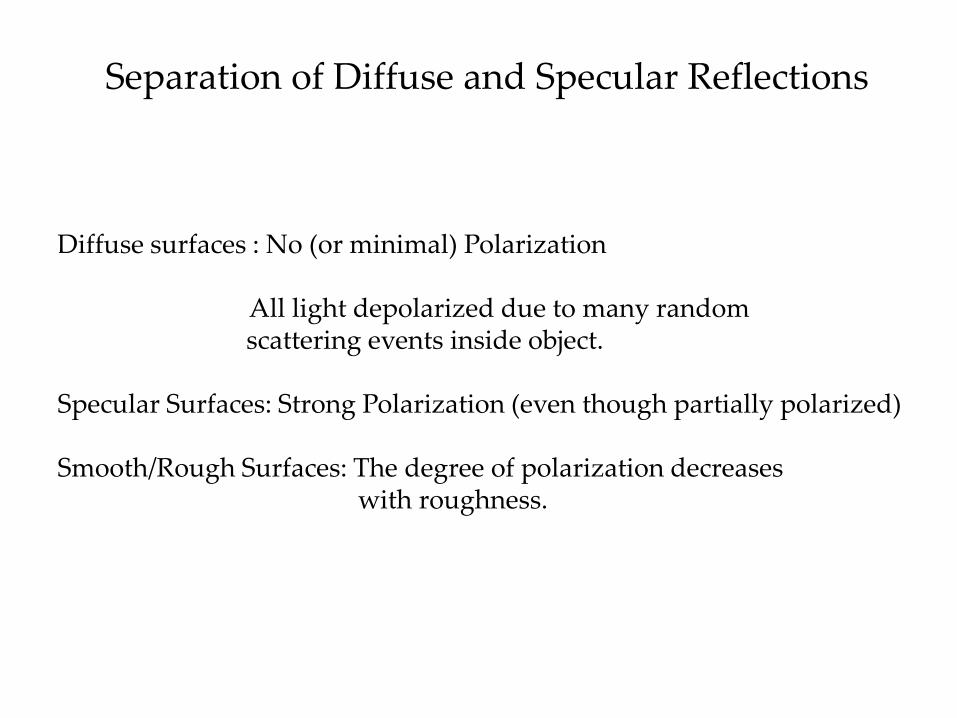
Separation of Diffuse and Specular Reflections
Diffuse surfaces : No (or minimal) Polarization All light depolarized due to many random scattering events inside object. Specular Surfaces: Strong Polarization (even though partially polarized) Smooth/Rough Surfaces: The degree of polarization decreases with roughness.

Active Illumination
•Completely remove specular reflections using polarized light when the filters are 90 degrees apart.
•Commonly used in industrial settings.
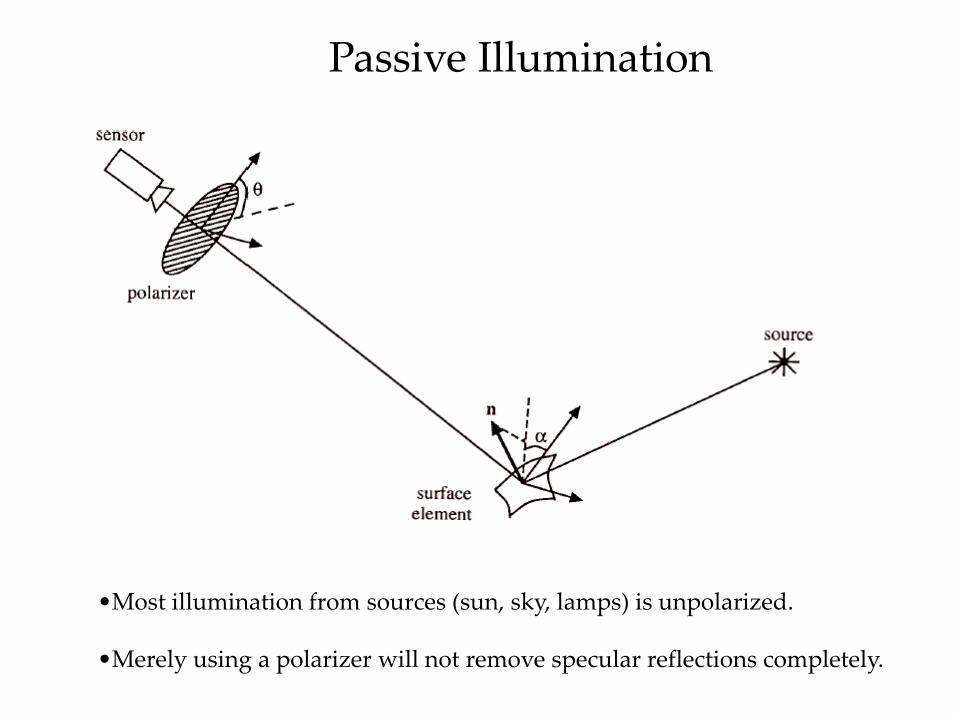
Passive Illumination
•Most illumination from sources (sun, sky, lamps) is unpolarized. •Merely using a polarizer will not remove specular reflections completely.
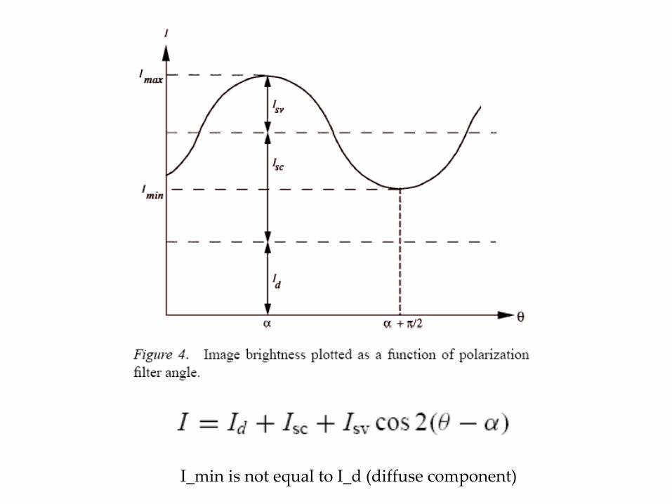
I_min is not equal to I_d (diffuse component)

polarizer
maxθ
180 o
minI
maxI
maxθ
3 general measurements suffice
Polarization vector determination
Polarization Measurements
camera

Determining the Polarization Cosine Curve
Using Vector Notation:
Three measurements suffice to determine the cosine curve.

Degree of Polarization
•Varies between 0 and 1. •If zero, then there is no polarization Only diffuse component present.
•If one, only specular component present.
•If degree of polarization does not change as polarizer is rotated, then there is no guarantee that specular component is completely removed (I_sc may still be present).

Fresnel Ratio
•I_sc and I_sv depend on refractive index and angle of incidence.
•I_sc and I_sv are related to fresnel coefficients:
is fresnel coefficient perpendicular to plane of incidence
is fresnel coefficient parallel to plane of incidence

Fresnel Ratio
Metals Dielectrics
•Hard to separate diffuse and specular parts for metals. •Easier for dielectrics (good for non-normal incidences).
Brewster angle

Dichromatic Model for Removing Specularities Completely
•Specularities are only reduced in intensity using polarization. •They are removed completely only for the Brewster angle of incidence.
•Nayar et al. use additional color constraints in dichromatic model to remove reflections completely. • Assume a local patch where the highlight and its surrounding area have the same diffuse component.

Semi-Reflections
Mic
hael
Opr
escu
, w
ww
.pho
to.n
et
•Both Reflected and Transmitted light are polarized. •But they are polarized differently.
•They depend on the orientation of the transparent layer.
•Reflections are removed completely only at Brewster Angle of Incidence.

window
Transparent Layers
camera

reflected scene RI
ϕϕ
window
Semi-Reflections transmitted
scene TI
camera

polarizer
ϕϕ
reflected scene rI
window camera
transmitted scene tI
r rI
r rI
0.2
0.4
0.6
0.8
20 60 40 80 ϕ
r r
Yoav Schechner, Joseph Shamir, Nahum Kiryati ‘99
Optical coding

polarizer r rI
r rI
ϕϕ
reflected scene rI
window
transmitted scene tI
t tI
t tI
0.2
0.4
0.6
0.8
20 60 40 80 ϕ
r r
t=1-r
Yoav Schechner, Joseph Shamir, Nahum Kiryati ‘99
camera
Optical coding

Yoav Schechner, Joseph Shamir, Nahum Kiryati ‘99
Experiment
window
reflected scene I r
I t transmitted
scene
observed image

Yoav Schechner, Joseph Shamir, Nahum Kiryati ‘99
Optical coding
window
reflected scene I r
I t transmitted
scene
observed image
I
t I + / 2 [ I = r I r ] t

Yoav Schechner, Joseph Shamir, Nahum Kiryati ‘99
window
reflected scene I r
I t transmitted
scene
observed image
I
I = [ r I r + t I t ] / 2
Optical coding

Yoav Schechner, Joseph Shamir, Nahum Kiryati ‘99
2 Linear equations I = [ r I r + t I t ] / 2 t I + / 2 [ I = r I r ] t
Window at 27 o Solve for 2 unknowns: I R I T ,
_
I
r r _ r 2 2 _
I
r r _ 2 _ r 2
I R Reflected
_
I
r r _ r 2
I
r r _ r 2
I T Transmitted
Digital decoding

The inclination of an invisible surface
0
0.4
0.4 _
0.8 _
20 10 30 40 50 ϕ
27 o
positive crosstalk
37 o
negative crosstalk
17 o
I T
Transmitted
I R
Reflected

clear day moderate haze very hazy
ww
w.h
azec
am.n
et
Imaging through Haze
Object + haze layers Scene structure Info about the aerosols
Recover: Previous work
Pure image processing Grewe & Brooks ’98, Kopeika ’98 Oakley & Satherley ’98
Physics based Nayar & Narasimhan ’99
Polarization filtering Shurcliff & Ballard ’64
Instant Dehazing: Yoav Schechner, Srinivasa Narasimhan, Shree Nayar

scattering
Airlight A
direct transmission
T
Imaging through Haze
camera
object radiance
R
Instant Dehazing: Yoav Schechner, Srinivasa Narasimhan, Shree Nayar

camera
object radiance
R Airlight A
scattering direct transmission
T
0
1
z
ze β−−1∞⋅ A
0
1
z
ze β− ),( yxR⋅
),( ),( ),(total yxAyxTyxI +=
z is a function of (x,y)
Multiplicative & additive models - similar dependence
Color

Polarization and Haze
polarizer
camera A
A
direct transmission
Along the line of sight, polarization state is distance invariant
Assume: The object is unpolarized 2/T @ all orientations
Plane of rays determines airlight components A A >
A A _
A A + ≡pAirlight degree of polarization
p=0 unpolarized A = A p=1 polarized =0 A
Instant Dehazing: Yoav Schechner, Srinivasa Narasimhan, Shree Nayar

I I
Trivial case
… still, there is a dominant polarization
Instant Dehazing: Yoav Schechner, Srinivasa Narasimhan, Shree Nayar
Life is tough…
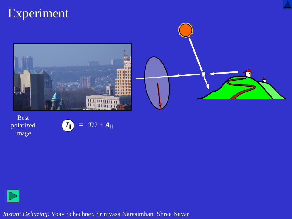
Best polarized
image
Experiment
I = A T/2 +
Instant Dehazing: Yoav Schechner, Srinivasa Narasimhan, Shree Nayar

Worst polarized
image
Experiment
= I T/2 + A
Instant Dehazing: Yoav Schechner, Srinivasa Narasimhan, Shree Nayar

I A + = 2 / T
I + = 2 / T A
2 input images:
Model
camera
object radiance
R airlight A
transmission T
_
βz e R T − = transmission
−
∞ = βz e A A - 1 airlight
A A A A +
≡ p polarization degree
Recovery
for known ∞ A p ,
βz e p I I I I R −
− − + = / ) ( ) ( radiance
( )/p − − − = I I e z 1 β depth ∞ A

I A + = 2 / T
I + = 2 / T A
2 input images:
Model
camera
βz e R T − = transmission
−
∞ = βz e A A - 1 airlight
_ A A A A +
≡ p polarization degree
saturated airlight
∞ A airlight
polarization p
Recovery
for known ∞ A p ,
βz e p I I I I R −
− − + = / ) ( ) ( radiance
( )/p − − − = I I e z 1 β depth ∞ A

Best polarized
image
I
Dehazing Experiment
Instant Dehazing: Yoav Schechner, Srinivasa Narasimhan, Shree Nayar

R
Dehazed image
Dehazing Experiment
Instant Dehazing: Yoav Schechner, Srinivasa Narasimhan, Shree Nayar

Range map
depth
)( , )( x,yIx,yIcomponent images
Airlight saturation polarization
∞Ap
)( yx,zβlog ( )
∞
− − − = pA
I I e z 1 β

Best polarized
image
I
Dehazing Experiment
Instant Dehazing: Yoav Schechner, Srinivasa Narasimhan, Shree Nayar

R
Dehazed image
Dehazing Experiment
Instant Dehazing: Yoav Schechner, Srinivasa Narasimhan, Shree Nayar
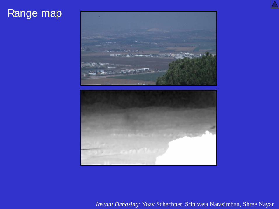
Range map
Instant Dehazing: Yoav Schechner, Srinivasa Narasimhan, Shree Nayar

total( , ) ( , ) ( , )I x y S x y B x y= +
effectiveobject ( , )L x y⋅
0
1
z
ze η−
0
1
z
1 ze η−− B∞
⋅+
z is a function of (x,y)
Color
- object with blur
light B veiling
S signal

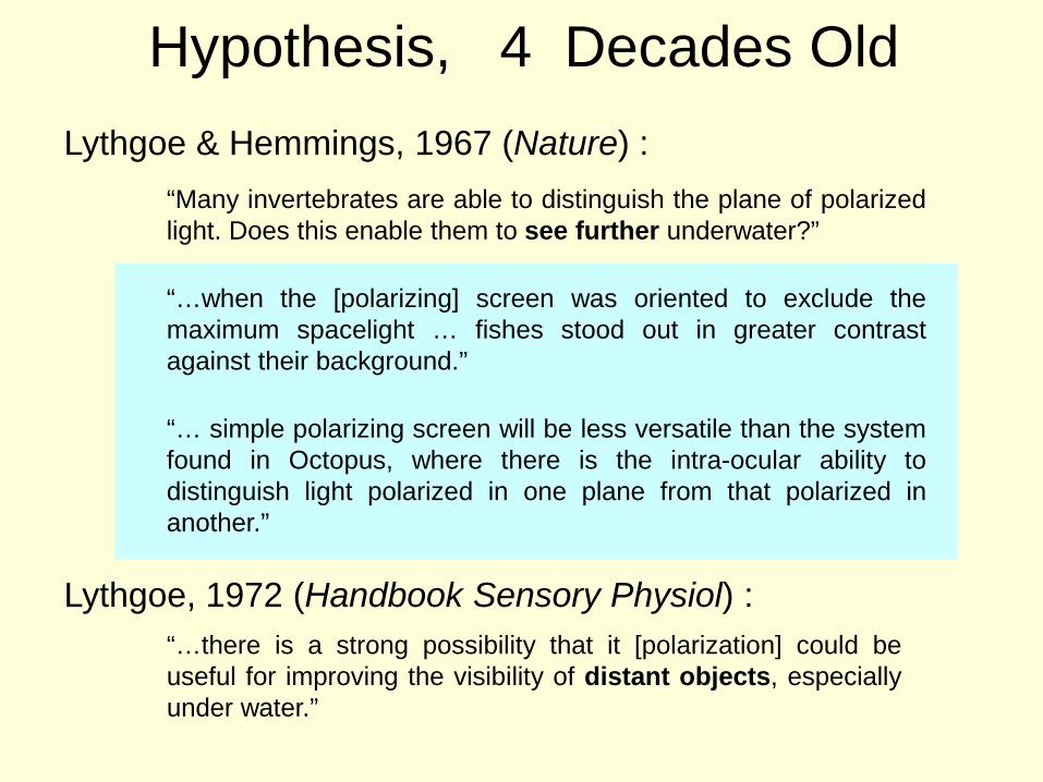
Hypothesis, 4 Decades Old
Lythgoe & Hemmings, 1967 (Nature) : “Many invertebrates are able to distinguish the plane of polarized light. Does this enable them to see further underwater?”
Lythgoe, 1972 (Handbook Sensory Physiol) : “…there is a strong possibility that it [polarization] could be useful for improving the visibility of distant objects, especially under water.”
Hypothesis, 4 Decades Old Lythgoe & Hemmings, 1967 (Nature) :
“Many invertebrates are able to distinguish the plane of polarized light. Does this enable them to see further underwater?”
“…when the [polarizing] screen was oriented to exclude the maximum spacelight … fishes stood out in greater contrast against their background.”
“… simple polarizing screen will be less versatile than the system found in Octopus, where there is the intra-ocular ability to distinguish light polarized in one plane from that polarized in another.”
Lythgoe, 1972 (Handbook Sensory Physiol) : “…there is a strong possibility that it [polarization] could be useful for improving the visibility of distant objects, especially under water.”

Polarization of Veiling Light
• Veiling light is partially polarized
B
B
Y. Schechner & N. Karpel, polarization-based recovery

Image Components
L light B veiling
S signal scattering
Veiling light = Spacelight = Path radiance = Backscatter
Schechner, Karpel, underwater vision
24

Signal Polarization
• Specular reflection : weaker than in air • Rough surfaces : naturally depolarize
• Multiple scattering • Signal decreases with distance / veiling-light increases
Y. Schechner & N. Karpel, polarization-based recovery
At large distance: signal polarization has a negligible effect
(Supported by Shashar, Sabbah & Cronin 2004)

Polarization Photography 25

Past Polarization-Based Methods
I min
Raw images
I max
Polarization-difference imaging
I max I min I max I min
I max I min
Degree of polarization

Model
2 input images:
camera
Recovery

2 input images:
Recovery
camera

Aqua-polaricam
Y. Schechner & N. Karpel, underwater imaging

Experiments

Best polarization image
Eilat, 26m underwater
I min
Experiment
Y. Schechner & N. Karpel, underwater imaging

Naive White Balancing
Y. Schechner & N. Karpel, underwater imaging
26m underwater

26m underwater
Y. Schechner & N. Karpel, underwater imaging

Range Map
Attenuation
Image components
backscatter
Y. Schechner & N. Karpel, underwater imaging

Shape Reconstruction of Transparent Objects Miyazaki et al
•Incident light is completely unpolarized. •Index of refraction is given. •Exploit relation between degree of polarization and angle of incidence (Surface normal).

Relationship between DOP and Angle of Incidence
Two-way ambiguity in recovered angle of incidence:
Manually disambiguate, use multiple views or use prior knowledge (convex, concave, etc).

Recovered Shape

Volumetric Scattering and its Applications to Computer Vision and Computer Graphics
Lectures #18, #19, #20
NEXT WEEK