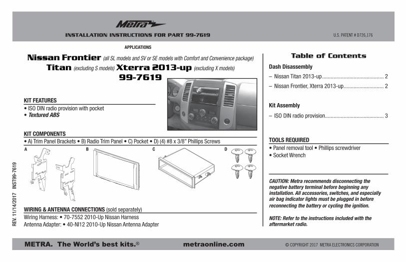
APPLICATIONS Nissan Frontier Titan (excluding S models ... · Nissan Frontier (all SL models and SV...
8
METRA. The World’s best kits. ® metraonline.com © COPYRIGHT 2017 METRA ELECTRONICS CORPORATION REV. 11/14/2017 INST99-7619 CAUTION: Metra recommends disconnecting the negative battery terminal before beginning any installation. All accessories, switches, and especially air bag indicator lights must be plugged in before reconnecting the battery or cycling the ignition. NOTE: Refer to the instructions included with the aftermarket radio. Table of Contents APPLICATIONS INSTALLATION INSTRUCTIONS FOR PART 99-7619 ® U.S. PATENT # D726,176 • ISO DIN radio provision with pocket • Textured ABS • A) Trim Panel Brackets • B) Radio Trim Panel • C) Pocket • D) (4) #8 x 3/8” Phillips Screws KIT FEATURES KIT COMPONENTS WIRING & ANTENNA CONNECTIONS (sold separately) Wiring Harness: • 70-7552 2010-Up Nissan Harness Antenna Adapter: • 40-NI12 2010-Up Nissan Antenna Adapter • Panel removal tool • Phillips screwdriver • Socket Wrench TOOLS REQUIRED Nissan Frontier (all SL models and SV or SE models with Comfort and Convenience package) Titan (excluding S models) Xterra 2013-up (excluding X models) 99-7619 A B C D Dash Disassembly – Nissan Titan 2013-up ........................................... 2 – Nissan Frontier, Xterra 2013-up............................ 2 Kit Assembly – ISO DIN radio provision......................................... 3
Transcript of APPLICATIONS Nissan Frontier Titan (excluding S models ... · Nissan Frontier (all SL models and SV...
METRA. The World’s best kits.® metraonline.com © COPYRIGHT 2017 METRA ELECTRONICS CORPORATION
REV.
11/
14/2
017
INS
T99-
7619
CAUTION: Metra recommends disconnecting the negative battery terminal before beginning any installation. All accessories, switches, and especially air bag indicator lights must be plugged in before reconnecting the battery or cycling the ignition.
NOTE: Refer to the instructions included with the aftermarket radio.
Table of ContentsAPPLICATIONS
INSTALLATION INSTRUCTIONS FOR PART 99-7619
®
U.S. PATENT # D726,176
• ISO DIN radio provision with pocket• Textured ABS
• A) Trim Panel Brackets • B) Radio Trim Panel • C) Pocket • D) (4) #8 x 3/8” Phillips Screws
KIT FEATURES
KIT COMPONENTS
WIRING & ANTENNA CONNECTIONS (sold separately)Wiring Harness: • 70-7552 2010-Up Nissan HarnessAntenna Adapter: • 40-NI12 2010-Up Nissan Antenna Adapter
• Panel removal tool • Phillips screwdriver • Socket Wrench
TOOLS REQUIRED
Nissan Frontier (all SL models and SV or SE models with Comfort and Convenience package) Titan (excluding S models) Xterra 2013-up (excluding X models)
99-7619
A B C D
Dash Disassembly
– Nissan Titan 2013-up ........................................... 2
– Nissan Frontier, Xterra 2013-up ............................ 2
Kit Assembly
– ISO DIN radio provision......................................... 3
99-7619
®
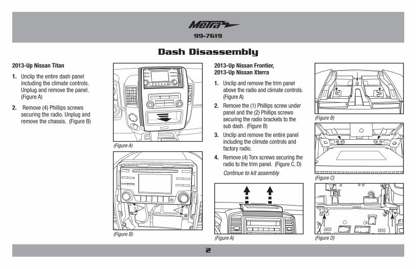
2013-Up Nissan Titan
1. Unclip the entire dash panel including the climate controls. Unplug and remove the panel. (Figure A)
2. Remove (4) Phillips screws securing the radio. Unplug and remove the chassis. (Figure B)
Dash Disassembly
(Figure A)
(Figure A)(Figure B)
(Figure C)
(Figure B)
(Figure D)
2
2013-Up Nissan Frontier, 2013-Up Nissan Xterra
1. Unclip and remove the trim panel above the radio and climate controls. (Figure A)
2. Remove the (1) Phillips screw under panel and the (2) Phillips screws securing the radio brackets to the sub dash. (Figure B)
3. Unclip and remove the entire panel including the climate controls and factory radio.
4. Remove (4) Torx screws securing the radio to the trim panel. (Figure C, D)
Continue to kit assembly
99-7619
®
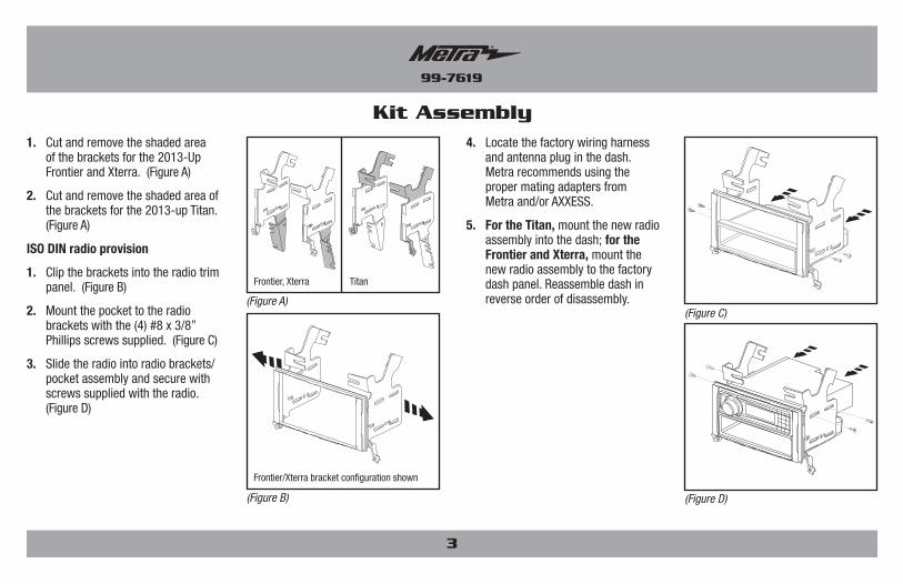
Kit Assembly
(Figure B)
(Figure C)
(Figure D)
(Figure A)
1. Cut and remove the shaded area of the brackets for the 2013-Up Frontier and Xterra. (Figure A)
2. Cut and remove the shaded area of the brackets for the 2013-up Titan. (Figure A)
ISO DIN radio provision
1. Clip the brackets into the radio trim panel. (Figure B)
2. Mount the pocket to the radio brackets with the (4) #8 x 3/8” Phillips screws supplied. (Figure C)
3. Slide the radio into radio brackets/pocket assembly and secure with screws supplied with the radio. (Figure D)
4. Locate the factory wiring harness and antenna plug in the dash. Metra recommends using the proper mating adapters from Metra and/or AXXESS.
5. For the Titan, mount the new radio assembly into the dash; for the Frontier and Xterra, mount the new radio assembly to the factory dash panel. Reassemble dash in reverse order of disassembly.
3
TitanFrontier, Xterra
Frontier/Xterra bracket configuration shown
METRA. The World’s best kits.® metraonline.com © COPYRIGHT 2017 METRA ELECTRONICS CORPORATION
REV.
11/
14/2
017
INS
T99-
7619
KNOWLEDGE IS POWEREnhance your installation and fabrication skills by enrolling in the most recognized and respected mobile electronics school in our industry.Log onto www.installerinstitute.com or call 800-354-6782 for more information and take steps toward a better tomorrow.
Metra recommends MECP certified technicians
INSTALLATION INSTRUCTIONS FOR PART 99-7619
®

INSTRUCCIONES DE INSTALACIÓN PARA LA PIEZA 99-7619
APLICACIONES
REV.
11/
14/2
017
INS
T99-
7619
PRECAUCIÓN: Metra recomienda desconectar el terminal negativo de la batería antes de comenzar cualquier instalación. Todos los accesorios, interruptores y, especialmente, las luces indicadoras de airbag deben estar enchufados antes de volver a conectar la batería o comenzar el ciclo de ignición.
Nota: Remítase a las instrucciones incluidas con el radio de posventa.
Indice
METRA. The World’s best kits.® metraonline.com © COPYRIGHT 2017 METRA ELECTRONICS CORPORATION
U.S. PATENT # D726,176
• Provisión de radio ISO DIN con cavidad• ABS texturizado
• A) Soportes del panel de moldura • B) Panel de moldura para radio • C) Cavidad • D) (4) tornillos Phillips #8 de 3/8”
CARACTERÍSTICAS DEL KIT
COMPONENTES DEL KIT
CABLEADO Y CONEXIONES DE ANTENA (se venden por separado)
Arnés de cableado: • Arnés 70-7552 para Nissan 2010 y más recientes
Adaptador de antena: • Adaptador de antena 40-NI12 para Nissan 2010 y más recientes
• Herramienta para quitar paneles • Destornillador Phillips • Llave para dados
HERRAMIENTAS REQUERIDAS
Desmontaje del tablero
– Nissan Titan 2013 y mas ...................................... 2
– Nissan Frontier, Xterra 2013 y mas ....................... 2
Ensamble del kit
– Provisión de radio ISO DIN con cavidad ................ 3
Nissan Frontier (todos los modelos SL y modelos SV y SE con comodidad y conveniencia paquete) Titan (excluidos los modelos S) Xterra 2013-y mas (excluidos los modelos X)
99-7619
A B C D

99-7619
Desmontaje del tablero
2
Nissan Titan 2013 y mas
1. Desenganche todo el panel del tablero, incluyendo los controles del clima. Desconecte y quite el panel. (Figura A)
2. Quite los (4) tornillos Phillips que sujetan el radio. Desconecte y quite el chasís. (Figura B)
(Figura A)
(Figura A)(Figura B)
(Figura C)
(Figura B)
(Figura D)
Nissan Frontier 2013 y mas Nissan Xterra 2013 y mas
1. Desenganche y quite el panel de moldura de arriba del radio y los controles del clima. (Figura A)
2. Quite el tornillo Phillips (1) de debajo del panel y los (2) tornillos Phillips que sujetan los soportes del radio al sub tablero. (Figura B)
3. Desenganche y quite todo el panel, incluyendo los controles del clima y el radio de fábrica.
4. Quite los (4) tornillos Torx que sujetan el radio al panel de la moldura. (Figura C, D)
Continue to kit assembly

99-7619
Ensamble del kit
3
(Figura B)
(Figura C)
(Figura D)
(Figura A)
1. Corte y quite el área sombreada de los soportes para la Frontier y Xterra 2013 y más recientes. (Figura A
2. Corte y quite el área sombreada de los soportes para la Titan 2013 y más recientes. (Figura A
Provisiones de unidad central ISO DIN.
1. Enganche los soportes en el panel de la moldura del radio. (Figura B)
2. Monte la cavidad en los soportes del radio con los (4) tornillos Phillips #8 de 3/8” suministrados. (Figura C)
3. Deslice el radio en el ensamble de los soportes del radio/cavidad y sujételo con los tornillos suministrados con el radio.
4. Ubique el arnés de cableado de fábrica y el conector de la antena en el tablero. Metra recomienda el uso de adaptadores adecuados de acoplamiento de Metra y/o de AXXESS.
5. Para la Titan, monte el nuevo ensamble de radio en el tablero; para la Frontier y la Xterra, monte el nuevo ensamble de radio en el panel del tablero de fábrica. Vuelva a armar el tablero al revés de como lo desarmó.
TitanFrontier, Xterra
Configuración del soporte de Frontier/Xterra muestra

INSTRUCCIONES DE INSTALACIÓN PARA LA PIEZA 99-7619
REV.
11/
14/2
017
INS
T99-
7619
KNOWLEDGE IS POWEREnhance your installation and fabrication skills by enrolling in the most recognized and respected mobile electronics school in our industry.Log onto www.installerinstitute.com or call 800-354-6782 for more information and take steps toward a better tomorrow.
Metra recomienda técnicos con certificación del Programa de Certificación en Electrónica Móvil (Mobile Electronics Certification Program, MECP).
EL CONOCIMIENTO ES PODERMejore sus habilidades de instalación y fabricación inscribiéndose en la escuela de dispositivos electrónicos móviles más reconocida y respetada de nuestra industria. Regístrese en www.installerinstitute.com o llame al 800-354-6782 para obtener más información y avance hacia un futuro mejor.
METRA. The World’s best kits.® metraonline.com © COPYRIGHT 2017 METRA ELECTRONICS CORPORATION