APPLICATIONS IN THE - NASA · PRELIMINARY DESIGN STUDY OF QUIET INTEGRAL ... APPLICATIONS IN THE...
294
a4479d I I CR 120969 FINAL REPORT PRELIMINARY DESIGN STUDY OF QUIET INTEGRAL FAN LIFT ENGINES FOR VTOL TRANSPORT APPLICATIONS IN THE 1980's BY G.R. Rabone E. Paulson GENERAL ELECTRIC COMPANY ." .. Prepared for NATIONAL AERONAUTICS AND SPACE ADMINISTRATION NASA Lewis Research Center Contract NAS3-14404 R. Roelke, Contract Manager https://ntrs.nasa.gov/search.jsp?R=19730018069 2018-07-27T15:10:34+00:00Z
Transcript of APPLICATIONS IN THE - NASA · PRELIMINARY DESIGN STUDY OF QUIET INTEGRAL ... APPLICATIONS IN THE...
a4479d I
I
C R 120969
F I N A L R E P O R T
P R E L I M I N A R Y D E S I G N S T U D Y OF Q U I E T I N T E G R A L F A N L I F T E N G I N E S F O R V T O L T R A N S P O R T
A P P L I C A T I O N S I N T H E 1980's
BY G.R. R a b o n e E . Paulson
GENERAL ELECTRIC COMPANY
." .. Prepared for
NATIONAL AERONAUTICS AND SPACE ADMINISTRATION
NASA L e w i s R e s e a r c h C e n t e r C o n t r a c t NAS3-14404
R. R o e l k e , C o n t r a c t Manager
https://ntrs.nasa.gov/search.jsp?R=19730018069 2018-07-27T15:10:34+00:00Z

4. Title and Subtitle
Fina l Report Preliminary Design Study of Qu ie t In t eg ra l Fan L i f t Engines f o r VTOL Transport Appl ica t ions i n t h e 1980's
7. Authork)
G.R. Rabone and E. Paulson ~
9. Performing Organization Name and Address
General E l e c t r i c Company Cinc inna t i , Ohiofiynn, Massachusetts
5. Report Date
6. Performing Organization Code June 1973
8. Performing Organization Report No.
10. Work Unit No.
11. Contract or Grant No. NAS3-14404
12. Sponsoring Agency Name and Address 13. Type of Report and Period Covered
Contrac tor Report
National Aeronautics and Space Administration Washington, D.C. 20546
17. Key Words (Suggested by Author(s))
14. Sponsoring Agency Code
18. Distribution Statement
NASA Dis t r ibu t ion
I
15. Supplementary Notes
19. Security Classif. (of this report) 20. Security Classif. (of this page) 21. NO. of Pages Unclass i f ied Unclassified
280
Contract Manager, R. Roelke NASA Research Center , Cleveland, Ohio 44135
22. Price'
-


TABLE OF CONTENTS
Page
ABSTRACT
1
5 INTRODUCTION
6 TASK I
6 GENERAL ENGINE DESIGN REQUIREMENTS
6 OBJECTIVES
6 CYCLE PARAMETRIC STUDY
COMPONENT S I Z I N G ArJD WEIGHTS S i z i n g P a r a m e t r i c Weights
11 11 12
13 WEIGHT FACTOR DEVELOPMENT
15 ACOUSTIC STUDY
19 RESULTS
23 REVISED ENGINE: REQUIREMENTS
24 ADDITIONAL RESULTS
25 RECOMMENDATIONS FOR TASK II/III
28 TASK I1
28 28 28
SELECTED ENGINE CHARACTERISTICS C o m p o n e n t P a r a m e t e r s Margins
29 29 29 30 31
MATERIALS SELECTION Select ion C r i t e r i a Material Forecasts A d d i t i o n a l C o n s i d e r a t i o n s R e p r e s e n t a t i v e Stress Leve l s
32 33 35 37 38 38 40
FAN AND COMPRESSOR DESIGN Fan A e r o d y n a m i c D e s i g n Supercharger A e r o d y n a m i c D e s i g n Fan and Supercharger Mechanical D e s i g n
R e q u i r e m e n t s Approach D e s i g n
iii

TABLE OF CONTENTS (Continued)
Page - Compressor Aerodynamic Design Flowpath Design Casing Treatment Blading Compressor Mechanical Design
BUSTOR DESIGN Requirements Combustor Aerodynamic Design F i r e Sa fe ty Engine Emissions
TURBINE DESIGN HP Turbine Aerodynamic Design Fan Drive Turbine Aerodynamic D e s i g n O u t l e t Guide Vane Turbine Cooling Design Cooled Turbine Performance High Pressure Turbine Mechanical Design
Requirements S t a t o r Rotor
Requirements S t a t o r Rotor Sha f t and Coupling
Low Pressure Turbine Mechanical Design
FRAMES DESIGN Main Frame Rear Frame
DUCT AND NOZZLE AERODYNAMIC DESIGN Fan Duct Core Duct Duct and Nozzle Mechanical Design
VECTORING SYSTEN DESIGN
BEARINGS, SEALS AND LUBE SYSTEM[ DESIGN Lubr ica t ing System Main Sha f t Bearings S e a l s
CONTROLS AND ACCESSORIES DESIGN In t roduc t ion System Desc r ip t ion Component Descr ip t ion
41 42 43 44 44
46 46 46 48 49
49 49 50 52 53 53 54 54 54 55 56 57 57 58 58
60 60 61
62 62 62 63
65
66 66 71 72
72 72 73 75
iv

TABLE OF CONTENTS ( C o n c luded)
TASK I11
ENGINE SERVICE REQUIREMENTS C o m m e r c i a l A i r c r a f t R e q u i r e m e n t s Pos tu la ted VTOL Mission E n g i n e Service L i f e D u t y C y c l e Maneuver Loads O t h e r E n g i n e Se rv ice C o n s i d e r a t i o n s
ACOUSTIC DESIGN CONSIDERATIONS C o m p o n e n t A n a l y s i s C o m p o n e n t P red ic t ion Technique C o m p o n e n t A c o u s t i c Features A c o u s t i c T r e a t m e n t D e s i g n
ENGINE ACOUSTIC ANALYSIS O b j e c t i v e s VTO Prof i les C o n s t i t u e n t Leve l s C o n s t i t u e n t s Suppression
ENGINE PERFORMANCE CHARACTERISTICS C o m p u t e r R e p r e s e n t a t i o n T y p i c a l R e s u l t s - U n i n s t a l l e d
INSTALLATION AERODYNAMICS AND ENGINE S T A B I L I T Y
TRANSIENTS AND STARTING CHARACTERISTICS
RESULTS
DISCUSSION OF RESULTS
CONCLUSIONS AND RECOMMENDATIONS
Page
80
80 80 80 81 82 84 86
86 86 87 89 91
92 92 93 93 94
95 95 96
97
99
102
103
105
SYMBOLS
V
107

LIST OF TABLES
Table I__
I.
I1 0
111.
I V .a
V .
V I e
V I I .
V I I I .
I X *
X.
X I *
X I I .
X I 1 1 D
X I V .
X V .
XVI 0
XVII *
XVIII e
XIX.
Turbine Cooling Technology.
Page
111
I_
Turbine Cooling Summary. 112
Summary R e s u l t s of I n i t i a l S i z i n g (Non-Geared). 113
Summary Resu l t s of. I n i t i a l S i z i n g (Geared Configurat ion) . 114
Non-Geared Reversed Flow Combustor. 115
Geared Reversed Flow Combustor. 116
I n t e g r a l L i f t Engine e ,117
Fan Design Parameter Summary. 118
ILFlAl Fan and Supercharger Vector Diagrams and Blading Summary. 119
ILF2A1 Fan and Supercharger Vector Diagrams and Blading Summary. 121
IW2A2 Fan and Supercharger Vector Diagrams and Blading Summary. 123
ILFlAl Compressor Vector Diagrams and Blading Summary. 125
ILF2A1 Compressor Vector Diagrams and Blading Summary. 129
ILFlAl Compressor and Supercharger Design Parameter Summary, 133
ILF2A1 Compressor and Supercharger Design Parameter Summary, 134
ILF2A1 Compressor and ILF2A2 Supercharger Design Parameter Summary, 135
E f f e c t of Casing Treatment on S t a l l Margin, 136
Core Turbines Vector Diagram Details. 13'7
Fan Drive Turbine Blading Summary. 138
v i

LIST OF TABLES (Concluded)
Table
XX.
=I.
XXII.
XXIII *
XXLV d
xxv.
XXVI *
XXVII.
X X V I I I .
ILFlAl Fan Drive Turbine Vector Diagram Details.
ILF2A1 Fan Drive Turbine Vector Diagram Details.
ILF2A2 Fan Drive Turbine Vector Diagram Details.
HP Turbine Cooling Design I n t e g r a l L i f t Fan Engines.
LP Turbine Cooling Design I n t e g r a l L i f t Fan Engine,
ILFlAl Turbine Performance I n t e g r a l L i f t Fan Engine.
ILF2A1 and ILF2A2 Turbine Performance I n t e g r a l L i f t Fan Engine.
Acoust ic S p l i t t e r Design.
Noise Cons t i t uen t s ,
Page
139
140
141
142
143
144
-
145
146
147
v i i

LIST OF ILLUSTRATIONS
Figure
1.
2.
3.
4.
5 .
6,
7.
8.
9.
10.
-11.
12.
13
14.
15.
16
17,
18.
19 0
20 a
21 e
22 0
Non- Geared Parametr ic Engine e
Geared Parametr ic Engine,
Re la t ion Between T i p Speed and Poly t ropic Ef f i c i ency f o r Parametr ic Study.
I n t e g r a l L i f t Fan Study Task I Se lec ted Re la t ion Between Fan P/P and T ip Speed.
I n t e g r a l L i f t Fan Engine Study Task I Parametr ic Data.
I n t e g r a l L i f t Fan Engine Study Task I Parametr ic Data.
I n t e g r a l L i f t Fan Engine Study Task I Paranfetric Data.
I n t e g r a l L i f t Fan Engine Study Task I Parametr ic Data.
I n t e g r a l L i f t Fan Engine Study Task I Parametr ic Data.
S i z i n g Procedures - Dimensions, Non-Geared Configurat ions.
S i z i n g Procedures - Dimensions, Geared Configurat ion.
E f f e c t of Fan Pressure Ra t io on POD S ize .
500 Foot S i d e l i n e Def in i t ion .
Acoust ic S p l i t t e r Suppression C h a r a c t e r i s t i c s .
I n l e t Suppression Requirements.
E f f e c t of Fan Suppression on T o t a l Noise.
N o i s e Cons t i t uen t s a t 10% Design Thrust,,
E f f e c t of Cycle Ex t rac t ion Ra t io on Jet Noise.
E f f e c t of C y c l e T4 on Jet Noise.
E f f e c t of Thrust on Suppressed Noise.
E f f e c t of Pressure Rat io on Noise.
Comparison of Non-Geared and Geared Suppressed Noise.
148
149
150
15 1
15 2
153
154
155
156
157
158
159
160
161
162
163
164
165
166
167
168
169
v i i i

LIST OF ILLUSTRATIONS (Continued)
Figure
23 .,
24 e
25
26
27 a
28 e
29.
30.
31.
32.
33 n
34 0
35 e
37 0
38
39 e
40
41
42 .,
43 0
44 El
45 e
EfIoc t of' Bludo Number on Non-Geared Noise.
Geared Unshrouded Fan Suppressed Noise.
Non-Geared Unshrouded Fan Suppressed Noise.
E f f e c t of Fan Pressure Ra t io on SFC.
E f f e c t of Fan Pressure Rat io on A Cru i se Fuel.
E f f e c t of Fan Pressure Rat io on Fan T ip Diameter.
E f f e c t of Fan Pressure Rat io on POD Weight.
Non-Geared Weight Cons t i t uen t s (.
Geared Weight C ons t it uent s.
Merit Fac to r Cons t i tuents .
E f f e c t of Fan Tip Speed.
E f f e c t of Fan Tip Speed.
E f f e c t of Fan P res su re Ratio and Tip Speed.
E f f e c t of Fan Pressure Ra t io and T i p Speed,
E f f e c t of C y c l e T4 and Core P/P.
E f f e c t of C y c l e T4 and Core P/P,
E f fec t of Ex t r ac t ion .
E f f e c t of Time i n L i f t .
E f f e c t of Range - VTOL Airplane.
E f f e c t of A l t e r n a t e STOL Mission.
E f f e c t of A l t e r n a t e Airplane,
Engine Weight Resu l t s - Recommended.
Weight Fac to r Resu l t s - Recommended,
Page
170
171
172
173
174
175
176
177
178
179
180
181
182
183
184
185
186
187
188
189
190
191
192
i x

LIST OF ILLUSTRATIONS (Continued)
Figure
46 e
47 9
48 *
49.
50.
51.
52.
53.
54.
55.
56.
57 .
58.
59.
60.
61.
62 e
63 e
64 e
65 I )
66 I)
67 e
68
E f f e c t of LPT Loading and Tip Speed on Number of LP Turbine S tages .
E f f e c t of LPT Loading on Engine Weight.
E f f e c t of LPT Loading on To ta l Weight Fac tor .
Noise Cons t i t uen t s .
T o t a l Noise Level wi th Turbine.
R e s u l t s - Bare Engine Weight.
Resu l t s - T o t a l Weight Fac tor .
E f f e c t of Tq and P/P Core on Fan Turbine I n l e t Temperature and Cooling Requirements.
Task II/III Component Arrangement.
Fans ILF2A1 and ILFlA1 Parametric Study.
Fan ILF2A2 Parametr ic Study.
Fan Flow Path I L F l A 1 .
Fan Flow Path ILF2A1.
Fan Flow Path ILF2A2.
Fan ILFlAl Performance Map.
Fan ILF2A1 Performance Map.
Fan ILF2A2 Performance Map.
Supercharger ILFlA1 and ILF2A1 Operat ing Line Performance.
Supercharger ILF2A2 Operat ing Line Performance.
Compressor Flow Path ILFlAl.
Compressor Flow Path ILF2A1 and ILF2A2,
Epoxy/Graphite Fan.
Fan.
193
194
195
196
197
198
199
200
201
202
203
204
205
206
207
208
209
210
211
212
213
214
215
X

LIST OF ILLUSTmTIONS (Continued)
Figure
69
70.
71.
72.
73 *
74.
75 (t
76.
77 s
78 e
79 0
80 a
81 a
82.
83.
84.
85 e
86
87 e
88.
89 a
90 e
91.
ILFlA1 Compressor Parametr ic Study.
ILF2A1 Compressor Parametric Study,
ILFlA1 Compressor Performance Map.
ILF2A1 Compressor Performance Map.
Ci rcumferent ia l Groove Casing Treatment Configurat ion.
Compressor Average Metal Temperature a
Combustor Flowpath ILFlA1.
Combustor Flowpath ILF2A1 and ILF2A2.
High Pressure Turbine Flowpath ILFlA1.
High Pressure Turbine Flowpath ILF2A1 and ILF2A2.
OGV Loss V s . D-Factor,
Low Pres su re Turbine Flowpath ILFlA1.
Low Pressure Turbine Flow Path ILF2A1.
Low Pressure Turbine Flow Pa th ILF2A2.
High P res su re Turbine Disc Stress. ,
Frame Arrangement.
Turbine R e a r Frame.
Trunnion Support.
Fan Duct Flowpath ILFlAl.
Fan Duct Flowpath ILF2Al.
Fan Duct Flowpath ILF2A2,
Core Duct Flowpath ILFlA1,
Core Duct Flowpath ILF2A1 and ILF2A2,
Page
216
21%
P
218
219
220.
221
222
223
224
224
225
226
2 27
228
229
230
23 1
232
233
234
235
236
237
x i

LIST OF ILLUSTRATIONS (Continued)
Figure
92 a
93.
94 0
95 e
96 e
97.
98.
99
100
101.
102.
103.
104 e
105.
106.
107 e
108.
109 *
110.
111.
112.
113 e
114.
115
Fan Duct D e t a i l .
Pod Cutaway.
Engine Support Beam.
Vectoring and Support System Cross Sec t ion .
I n t e g r a l L i f t Fan Lubr ica t ion System Schematic.
Cont ro ls & Accessor ies Schematic.
Control Block Diagrams.
Pump/Turbine C h a r a c t e r i s t i c s .
Cont ro ls & Accessor ies Package.
Con t ro l s and Accessor ies Packaging Schematic.
Engine Steady Maneuver Load Requirements.
Engine V e r t i c a l Landing Maneuver Load Requirements.
Engine Unpowered F l i g h t Maneuver Loads.
Engine Frequent Maneuver Load Requirements.
Engine Inf requent Maneuver Load Requirements.
ILFlAl V e r t i c a l Takeoff Noise (1.25 P/P).
ILF241 V e r t i c a l Takeoff Noise (1.20 P/P).
ILF2A2 V e r t i c a l Takeoff Noise (1.20 P/P).
V e r t i c a l Takeoff I n t e g r a l L i f t Fans.
Fan Suppression - ILFlAl.
Fan Suppression - ILF2A1.
Fan Suppression - ILF2A2.
I n l e t Noise Reduction Assumptions,
Unins ta l led Performance - Sea Level S t a t i c , 90° Day,
Page
23 8
239
240
241
242
243
244
245
246
247
. 248
249
25 0
25 1
25 2
25 3
25 4
255
25 6
25 7
25 8
25 9
260
26 1
-
xi i

LIST OF ILLUSTRATIONS (Concluded)
F igure
116.
117 ~
118.
119.
120.
121
122.
123
124.
125 e
126.
127 *
128.
129 e
130.
131
132
133
134
Page - Unins ta l led Performance - Sea Level S t a t i c , Standard Day, 262
Unins ta l led Performance - Sea Leve l S t a t i c , 90' Day. 263
I n t e g r a l L i f t Fan C h a r a c t e r i s t i c s . 264
Pod and Vectoring System Arrangement.
I n l e t and Exhaust Door Schematic
265
266
I n l e t Door Cross Sec t ion . 267
Exhaust Door C r o s s Sec t ion . 268
Typical VTOL Transport . 269
Objec t ive - Recovery of Assumed In l e t Design. 270
Objec t ive D i s t o r t i o n Parameter of Assumed I n l e t Design, 271
Crossflow V e l o c i t y Rat io as a Function of Power S e t t i n g . 272
Procedure f o r Est imat ing I n l e t D i s t o r t i o n E f f e c t s on Performance . 273
Crosswind D i s t o r t i o n E f f e c t s on Compressor Performance. 274
Crosswind D i s t o r t i o n E f f e c t s on Fan Performance.
Typical Takeoff Tra jec tory .
275
276
Typical Takeoff T ra j ec to ry . 277
E f f e c t of I n s t a l l a t i o n f o r T y p i c a l T ra j ec to ry Poin ts . 278
E f f e c t of I n s t a l l a t i o n f o r Typical T ra j ec to ry Poin ts . 279
Ef fec t of I n s t a l l a t i o n f o r T y p i c a l T ra j ec to ry Resul t s . 280
x i i i

SUMMARY
Prel iminary design s t u d i e s were conducted f o r t h r e e low n o i s e i n t e g r a l
l i f t fan engines c o n s i s t e n t with commerical c e r t i f i c a t i o n i n 1980's.
Important engine c h a r a c t e r i s t i c s are summarized i n t h e fol lowing t a b l e .
Weights i n d i c a t e d inc lude a l l commercially requi red f e a t u r e s of f i r e s a f e t y
and containment
Engine
Bypass Ra t io
FN F l a t Rated t o 90" F
Noise Rat ing P o i n t , 90" F
Fan Tip Diameter - i n .
Engine Max. D i a m e t e r - i n .
Overa l l Length - i n .
Length/Diameter
Overa l l Weight (with Treatment) l b
Overa l l Weight (without Treatment) l b a
Lift /Weight Ra t io , 90" Day 3 Volume - f t .
Lift/Volume - l b / f t .
F r o n t a l Area - f t .
L i f t / F r o n t a l Area l b / f t e
PNdB @ 500' S i d e l i n e , 1 2 @ 10,000 l b .
SFC
Fan P/P
Overall P/P
Fan Tip Speed
Turbine I n l e t Temperature " F
3
2
2
ILFlAl
12.6
12 500
10,000
57.1
69.8
43.5
0.62
1050
9 80
11.9
96
130
21
595
96
0.36
1.25
10
11 80
2500
ILF2A1
11.6
12,500
10 9 000
60
74
50.6
0.68
1140
1070
10.9
126
99
26
480
95
0.36
1.20
7
1060
2000
ILF2A2
11.7
12 500
10,000
60
74
54.5
0.74
1250
11 70
10
136
92
28
445
95
0.36
1.20
7
855
2000
O f paramount importance w a s low n o i s e and t h i s w a s r e f l e c t e d i n every f a c e t
of t h e s tudy; cyc le s e l e c t i o n , weight and envelope.
a t t a i n i n g t h i s n o i s e level along wi th assumptions and u n c e r t a i n t i e s involved is
descr ibed i n t h e body of t h e r e p o r t .
The design r a t i o n a l e f o r

ILFlAl Features
Fan Pressure Ratio 1.25 Bypass 12.6 Fan Tip Speed 1180 ' /sec Turbine In l e t 2500' F
ILFOAl Features
Fan Pressure Ratio 1.20 Bypass 11.6 Fan Tip Speed 1060 ' /sec Turbine In l e t 2000' F
ILF2A2 Features
Fan Pressure Ratio 1.2 Bypass 11.6 Fan Tip Speed 855 ' /sec Turbine In l e t 2000' F
2

The cyc les f o r t h e t h r e e pre l iminary designs were s e l e c t e d based on t h e
r e s u l t s of a parametr ic s tudy of t h e no i se , weight, and performance charac te r -
i s t i c s of more than f o r t y candida te designs. A s imple weight merit f a c t o r
based upon an assumed VTOL mission was u t i l i z e d as an o v e r a l l measure of
envelope, weight, and performance e f f e c t s and compared wi th t h e n o i s e levels f o r each cycle .
Component aerodynamic and mechanical des igns were completed f o r each
component, using materials and technology c o n s i s t e n t with t h e 1980 time
per iod . Emphasis w a s p laced on achieving a compact design with a s m a l l
number of s t ages which i n t u r n allowed a s imple r o t o r and s t r u c t u r a l arrange-
ment. Engine system l ayou t s were completed i n t h e f i n a l phase of t h e e f f o r t
and engine of f design performance estimates completed f o r a range of ope ra t ing
condi t ions . Weight a n a l y s i s based on t h e layouts and component des igns
i n d i c a t e t h a t l i f t t o weight r a t i o s of from 10-12 w i l l r e s u l t from t h e s e l e c t e d
cyc les . This level of t h r u s t t o weight r a t i o i s a consequence of t h e very low
engine no i se requirement (about 84 PNdB f o r one engine a t 500' s i d e l i n e and
10,000 l b e t h r u s t on a 90" day) .
The payoff i n use of advanced technology i s r e f l e c t e d i n t h e favorable
s i z e , weight and volume of t h e engines , p a r t i c u l a r l y t h e 2500" F T 4 ILFlA1.
Weight and s i z e c h a r a c t e r i s t i c s r e s u l t from t h e a p p l i c a t i o n of advanced
composite materials i n t h e f a n , compressor, and duc t ; use of a compact 7:l 4-stage o r 10: l 5-stage compressor; a high space r a t e reverse l i n e r flow
combustor l oca t ed over t h e compressor; and a very highly-loaded 3-stage fan
t u r b i n e wi th an OGV system.
Considering t h e a p p l i c a t i o n of t h e s e conceptsg several component areas
s tood out wi th regard t o need f o r s u b s t a n t i a l f u t u r e development. The most
prominent of t h e s e are:
Techniques f o r fan and core source n o i s e reduct ion and suppress ion
I n s t a l l a t i o n aerodynamics f o r compatible a i r f rame/engine design
Composite b lade , shroud, and d o v e t a i l design and cons t ruc t ion
3

5-stage, 10:1 P /P core compressor
Low emission r eve r se l i n e r flow combustor w i th 2500" F T
Very h igh ly loaded fan t u r b i n e
A l l e l e c t r o n i c f u e l c o n t r o l s
4
4

INTRODUCTION
Recognition has been inc reas ing concerning t h e need f o r s a f e , q u i e t ,
and economical aLr t r a n s p o r t a t i o n between c i t y cen te r s of from 200 t o 500
m i l e d i s t ance . A V/STOL commerical t r a n s p o r t having a passenger capac i ty of
from 100 t o 150 appears t o have t h e p o t e n t i a l of c o n t r i b u t i n g t o meeting
t h i s need i n combination wi th o t h e r a i r and s u r f a c e systems i n t h e 1985
t i m e frame.
NASA Ames and NASA L e w i s are sponsoring indus t ry s t u d i e s on bo th n e a r
term V/STOL research v e h i c l e s and p o t e n t i a l 1985 commercial t r a n s p o r t s .
The p resen t work of t h i s r e p o r t is concerned wi th provid ing pre l iminary
designs of several i n t e g r a l fan l i f t engines to NASA L e w i s which i n t u r n
provide i n s i g h t s i n t o r equ i r ed f u t u r e developments. Data provided inc lude :
component c h a r a c t e r i s t i c s , engine performance, engine design c h a r a c t e r i s t i c s ,
n o i s e estimates, and engine weight and envelope.
The work w a s d iv ided i n t o t h r e e phases: A cyc le paramet r ic s tudy t o
select t h e cyc le s f o r f u r t h e r s tudy , pre l iminary component des igns f o r t h e
s e l e c t e d c y c l e s 9 and engine system l ayou t s w i t h n o i s e and weight estimates.
The e f f o r t w a s completed over a fourteen-month pe r iod s t a r t i n g on June 2 4 ,
-1970 and ending on August 31, 1971.
5

TASK I
GENERAI, ENGINE DESIGN REQUIREMENTS
I n i t i a l Design Requirements as set f o r t h i n t h e s ta tement of work are
as fol lows :
1. Maximum s i d e l i n e n o i s e a t 500' of 95 PNdB f o r one engine.
2 .
3 .
4.
5 . Hot p a r t TBO a t service ma tu r i ty of 10,000 cyc le s .
10,000 l b . FN f o r 90" day.
30 second contingency r a t i n g a t 11,000 l b . FN.
0.3 second response t i m e f o r 10% FN i n c r e a s e above 60% t h r u s t .
6 . Cold p a r t l i f e 5000 hours a t service matur i ty .
7. Capab i l i t y f o r vec to r ing 15" forward and 45' a f t .
8. No v i s i b l e smoke.
9. FAA t e n t a t i v e a i rwor th iness s tandards f o r V/STOL.
Addi t iona l design requirements imposed by t h e na tu re of t h e a p p l i c a t i o n
w e r e low c o s t , s i m p l i c i t y , and low weight , c o n s i s t e n t w i th o t h e r requirements .
OBJECTIVES
The o b j e c t i v e s of Task I were t o survey a wide range of cyc le parameters
and determine t h e i r e f f e c t on o v e r a l l engine envelope s i z e , weight , performance,
n o i s e c h a r a c t e r i s t i c s , and on a s imple weight merit f a c t o r r e f l e c t i n g a conibin-
a t i o n of weight , s i z e , and performance. From t h e s e r e s u l t s a recommendation
w i l l b e made as t o t h e two o r t h r e e cyc les t o b e s e l e c t e d f o r more d e t a i l e d
design dur ing Tasks I1 and 111.
CYCLE PAMMETRIC STUDY
A s p l i t f low fan conf igu ra t ion w a s chosen f o r t h e b a s e l i n e case. See
Figures 1 and 2. Both geared and d i r e c t d r i v e conf igura t ions were eva lua ted
i n Task I.
s y s t e m a t i c a l l y va r i ed .
Base l ine cyc le s were s e l e c t e d , about which parameters were
The Task I b a s e l i n e cyc le s which were s e l e c t e d were:
6

Non Geared Geared
1 .4 Fan P res su re Rat io 1 . 3
10 Overall P res su re Ra t io 10
2500 Turbine I n l e t Temperature F 2500
1.3 '8"28' 1200
Ex t rac t ion Rat io 1 ,3 ----
(1165 UT/&-)
8.8 $, Bypass Ra t io
Fan T i p Speed 90" F 1069 (1035 U T / 6 - )
12.4
Components s e l e c t e d f o r the baseline non-geared conf igu ra t ion included
a high t ip-speed s p l i t f low fan. A high tip-speed axial flow compressor9
a high space rate ca rbure t ing combustor, a s ing le - s t age h igh p res su re t u r b i n e ,
a highly-loaded low p res su re t u r b i n e , s h o r t duct w i th acous t i c s s p l i t t e r s ,
and a t runca ted core nozzle . The components f o r t h e geared des ign are the
same except f o r a lower tip-speed f a n and a more moderate low p res su re t u r b i n e
loading. These c h a r a c t e r i s t i c s being c o n s i s t e n t w i t h the f a n and low-pressure
t u r b i n e speed mismatch made poss ib l e wi th t h e u s e of t h e r educ t ion gear ing ,
The choice of a highly-loaded f a n t u r b i n e w a s d i c t a t e d by a d e s i r e f o r a s h o r t
engine, and the r e a l i z a t i o n of t h e relative unimportance of SFC f o r a n engine
used only a few minutes of every mission.
S p e c i f i c c h a r a c t e r i s t i c s of components assumed i n Task I were:
In t eg ra t ed OGV and frame
Unshrouded Graphite/Polyimide composite b l ade
Reduced v e l o c i t y parameter = cons t .
Radius r a t i o - > 0.37
1 .4 t i p s o l i d i t y
Wm6A = 41.3
20% s t a l l margin
np a f u n c t i o n of co r rec t ed t i p speed (Figure 3)
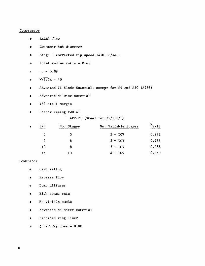
Compress o r
Axial flow
Constant hub diameter
Stage 1 correc ted t i p speed 1450 f t / s e c .
I n l e t r ad ius r a t i o = 0.65
np = 0.89
Wm6A = 40
Advanced T i Blade Material, except f o r S9 and S10 (A286)
Advanced N i D i s c Material
18% s t a l l margin
S t a t o r cas ing FWD-A1
AFT-Ti ( S t e e l f o r 15/1 P/P>
- P/P No. Stages No. Var iab le Stages Mex i t
5 5 2 + IGV 0.292
5 6 2 + IGV 0.286
10 8 3 + IGV 0.288
15 10 4 + IGV 0,250
Comb us t o r
Carburet ing
Reverse flow
Dump d i f f u s e r
High space rate
No v i s i b l e smoke
Advanced N i s h e e t material
Machined r i n g l i n e r
A P/P dry loss = 0.08
8

riB = 0,985
70' /sec ). r e fe rence v e l o c i t y
P a t t e r n f a c t o r - 0.2
H/L = 2.5
High P res su re Turbine
Axial flow
e Sing le s t a g e
nT = 0.89
'coolant Loading (JGAHI2U ) =1.0
P Advanced N i based b lade material
= f (T & T 1, Table I and I1 3 42
Advanced N i based d i s c material
Low Pres su re Turbine
Non-Geared
Axial f low
Stages as requi red
n t = f ( loading) JGAH/2U
0,89 1.7
0.85 2.5
P
= f (T54 15 T3) Table I & I1 'coolant OGV AP/P = 0.02 - 0.03
Swi r l = 20" - 40"
Exltt r a d i u s r a t i o - > 0.55
Frames and Ducts
Containment allowance i n weight
I n t e g r a l t u r b i n e frame/OGV
Duct t rea tment i n t e g r a l w i t h s t r u c t u r e
Geared
Axial flow
2 Stage
Loading 1-1 3
'coolant = f (T54 T31 Table I &
O W AP/P - 0.02
Swi r l = 20"
Exit r a d i u s 0 ,55
Duct l e n g t h = engine l e n g t h
9

Aluminum and composite f a n frame
Separated flow
AP/P f a n duc t IQI 0.02
AP/P core duct * 0.01
Fan and core nozzle C = 0.99
Truncated core nozzle
Trunnions on ou te r r i n g
V
Bearings
6 e Max. Dn = 3 . 2 x 10 f o r l a r g e f r o n t bear ing
e Ausformed M-40 Material
Cont ro ls and Accessories
0
8
0
Q
Gearing
8
10
Bleed d r iven accesso r i e s
Impingement a i r s t a r t i n g
Swiveling engine vec to r ing
Fuel /Oi l hea t exchanger (geared f a n )
Gear Loss - 0.005
Maximum 5 sun gea r s
K Fac tor = 600
Minimum pin ion p i t c h diameter = 3.5 inches
Minimum r i n g p i t c h diameter
S t e e l g e a r s , s h a f t s and bear ings
Root stress = 45,000 l b . / i n ,
Other components T i c o n s i s t e n t w i t h 1975 demonstrator
Double herr ingbone, toothwidth - < p i t c h diameter
2
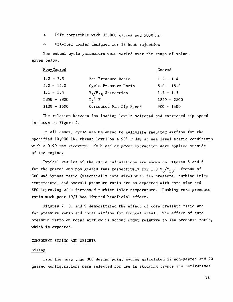
Life-compatible with 35,000 cyc les and 5000 h r .
ta Oil - fue l coo le r designed f o r 1% h e a t r e j e c t i o n
The a c t u a l cyc le parameters were va r i ed over t h e range of va lues
given below *
Non-Geared Geared
1 .2 - 1.5 Fan Pressure Ra t io 1 . 2 - 1.4
5.0 - 15.0 Cycle P res su re Ra t io 5 , O - 15.0
1.1 - 1.5 V8/VZ8 Ex t r ac t ion 1.1 - 1.5
1850 - 2800 T40 F 1850 - 2800
1100 - 1600 Corrected Fan Tip Speed 900 - 1400
The r e l a t i o n between fan loading l e v e l s s e l e c t e d and co r rec t ed t i p speed
is shown on Figure 4 .
I n a l l cases, cyc le w a s balanced t o c a l c u l a t e requi red a i r f low f o r t h e
s p e c i f i e d 10,000 l b . t h r u s t level on a 90' F day a t sea l e v e l s t a t i c cond i t ions
wi th a 0,99 ram recovery. No b leed o r power e x t r a c t i o n were app l i ed o u t s i d e
of t h e engine.
Typica l r e s u l t s of t h e cyc le c a l c u l a t i o n s are shown on Figures 5 and 6
f o r t h e geared and non-geared fans r e spec t ive ly f o r 1 . 3 V8/V28e
SFC and bypass r a t i o ( e s s e n t i a l l y core s i z e ) w i th f a n p res su res t u r b i n e i n l e t
temperature , and o v e r a l l p re s su re r a t i o are as expected wi th core s i z e and
SFC improving wi th increased t u r b i n e i n l e t temperature . Pushing core p re s su re
r a t i o much p a s t 1 0 / 1 has l i m i t e d b e n e f i c i a l e f f e c t .
Trends of
F igures 7 , 8, and 9 demonstrated t h e e f f e c t of core p re s su re r a t i o and
f a n p res su re r a t i o and t o t a l a i r f l o w (o r f r o n t a l area). The e f f e c t of core
pressure r a t i o on t o t a l a i r f l o w i s second o rde r relative t o fan p res su re r a t i o ,
which i s expected,
COMPONENT SIZING AND WEIGHTS
S i z i n g
From t h e more than 300 design p o i n t cyc le s c a l c u l a t e d 22 non-geared and 20
geared conf igu ra t ions w e r e s e l e c t e d f o r use i n s tudying t r ends and d e r i v a t i v e s
11

about t h e s e l e c t e d b a s e l i n e cases.
one a t a time t o eva lua te e f f e c t of t i p speed, f a n p re s su re r a t i o , V /V o v e r a l l p re s su re r a t i o , and t u r b i n e i n l e t temperature , on no i se , weight ,
performance and m e r i t f a c t o r .
Parameters were sys t ema t i ca l ly v a r i e d
8 28'
Actual s i z i n g of components w a s d e l i b e r a t e l y kept c o n s i s t e n t by a
sys temat ic procedure which used f ixed va lues of f a n and compressor s p e c i f i c
f low and f i x e d r e l a t i o n s h i p between core compressor t i p diameter arid h igh
p res su re t u r b i n e p i t c h diameter . Fan i n l e t r a d i u s r a t i o and low p res su re
t u r b i n e exit r ad ius r a t i o were not allowed t o f a l l below 0.36 and 0.55
r e s p e c t f u l l y . Reduction gear s i z e was pos tu l a t ed as a f u n c t i o n of speed
r educ t ion r a t i o . Low p res su re t u r b i n e loading f o r t h e non-geared cases w a s
allowed t o vary s l i g h t l y t o achieve an i n t e g r a l number of s t a g e s , us ing a
l as t s t a g e loading less than average t o l i m i t e x i t s w i r l . Case I A of
Table I11 w a s undertaken t o e v a l u a t e t h e e f f e c t of us ing a very h igh f a n
t u r b i n e loading .
Resu l t s of t h e s i z i n g procedure, and t h e cases s e l e c t e d f o r a d d i t i o n a l
eva lua t ion are shown on Tables I11 and IV and Figures 10 and 11.
Parametr ic Weights
The paramet r ic weights f o r t he cases l i s t e d on Table IV and Figure 11
were generated by making pre l iminary designs of t he b a s e l i n e engine ' s
components, and then applying scale f a c t o r s t o c o r r e c t f o r s i z e . Th i s
procedure w a s used t o produce a l a r g e number of weight estimates being
c o n s i s t e n t among themselves, bu t wi th reduced abso lu te accuracy i n l i n e
w i t h t h e o b j e c t i v e s of t h e paramet r ic p o r t i o n of t h e s tudy.
@eigh t /Bas e Weight )
Component
Rotors
S t a t o r s
Combus t o r
S t r u c t u r e s
Duct i a g
B.earings & Sea l s
Drives
Augment o r
C&A
Nozzle
C (Diameter/Base Diameter)
Exponent "C"
2.80
2.60
2.20
1.75
2.2Q
2.30
2,OO 2.00
1.80
2.50
12

The r e s u l t s of t h e procedure descr ibed above are shown on T a b l e s V and V I ,
WEIGHT FACTOR DEVELOPMENT
I n o rde r no t t o l i m i t comparisons among candida te cyc les t o c h a r a c t e r i s t i c s
of t h e i s o l t a t e d engine, a s imple mission weight (mer i t ) f a c t o r w a s evolved
wi th t h e ob jec t ive of genera t ing a number which would be a more r e a l i s t i c
eva lua t ion of an " i n s t a l l e d " propuls ion sys t e m ,
This weight f a c t o r i s t h e summation of f ive weight elements as l i s t e d below:
Engine weight
Fuel used i n l i f t
POD weight p e r l i f t engine
Acoust ic t rea tment weight
Incremental c r u i s e f u e l
The base mission and a i r p l a n e assumptions were as fol lows:
10 x 10,000 l b . l i f t engines wi th gimbaled vec to r ing
2 x 24,000 l b . vec to rab le c r u i s e engines
L i f t engine i n s t a l l e d i n two engine pods (See Figure 12)
@ Airplane TOGW = 109,500 1bse
2 Wing area = 841 f t a
Cd = 0.03
Cruise @ Mo = 0.75 20,000 f t ,
500 NM range
2 minutes at 80% FN i n l f f t / m i s s i o n
4 minutes a t i d l e l m i s s i o n
Basic engine weight is as ca l cu la t ed .

Fuel used by l i f t engine per mission i s c a l c u l a t e d by t h e cyc le
performance SFC and t h e assumed time i n l i f t and a t i d l e .
POD weight pe r engine is ca l cu la t ed from t h e t o t a l number of square
f e e t of s h e e t metal, inc luding a n allowance f o r i n l e t and exhaust door s ,
r equ i r ed t o cover a f ive-engine pod wi th gimbaled engines .
l b / f t w a s assumed,
t o be c o n s i s t e n t wi th t h e s i n g l e engine b a s i s of t h e weight f a c t o r .
A weight of 2.7 2 The t o t a l weight ca l cu la t ed i s then d iv ided by f i v e
The weight of duc t and i n l e t a c o u s t i c t rea tment i s included as
c a l c u l a t e d . The weight of t h e a c o u s t i c t reatment is c o n s i s t e n t wi th t h e noise
d a t a presented i n t h e a c o u s t i c s ec t ion .
The incrementa l c r u i s e f u e l ca l cu la t ed i s intended t o be a measure of
how t h e phys ica l s i z e of t h e l i f t engine pod a f f e c t s t h e f u e l used by the
c r u i s e engines dur ing t h e c r u i s e p o r t i o n of t h e mission.
pod drag is c a l c u l a t e d f o r t h e five-engine pod, and t h i s drag i s cor rec ted
i n t o a n equ iva len t f u e l weight pe r l i f t engine.
An incremental
Where : y = 1 . 4
M L=I c r u i s e Mach no.
Po = ambient s ta t ic p res su re
= pod wetted t o t a l area Awet Cdf = 0.002 F r i c t i o n Drag Coef f i c i en t
CR = 1.05 Roughness Factor
F'p = 1.60/(L/D)
L/D = pod Fineness Rat io
0
3 $. 0.0025(L/D) P res su re Drag Form Factor
Kn a d d i t i o n t 9 the b a s e l i n e mission descr ibed above, alternate miss ions
and a l t e r n a t e a i r p l a n e s were eva lua ted i n o rde r t o determine the s e n s i t i v i t y
weight f a c t o r t o assumed miss ion and a i r c r a f t .
A l t e r n a t e MZssions
1 minute i n l i f t , 4 minutes i n l i f t
200 and 800 NM range
Max, TOGW (STOL) Mo = 0.8 35OOs, 200 NM range
14

81 t e r n a t e Airplane (STOL)
G- 4 x 10,000 l b , l i f t engines
e 2 x 21,000 lb, c r u i s e engines
0,75 20,000' 500 W
e? 0,80 35,000' 2000 NMI:
ACOUSTIC STUDY
Considering the importance of t h e no i se a s p e c t s of t he s tudy , g r e a t care
w a s t aken t o apply c o n s i s t e n t methods of eva lua t ion t o a l l engines , Unsup-
pressed noise p r e d i c t i o n s were based on t h e fo l lowing assumptions,
Q Vertical Engine Axis
a Angles from I n l e t I < 90' no t p e r t i n e n t
@ Aircraft ou t of Ground E f f e c t (less a t t e n u a t i o n wi th d i s t a n c e )
Fan Noise - Analy t ica l /Empfr ica l
8 Jet Noise - SAE Extrapola ted f o r Je t V e l o c i t i e s less than 180Oe/sec
No Relative Veloc i ty E f f e c t on Jet Noise
@ Turbine Noise - Empir ical
Q 500' S i d e l i n e as Defined i n F igure 13
Suppressed no i se estimates were made assuming t h a t advances i n a c o u s t i c
technology between t h e p re sen t t i m e and t h e 19809s time period would provide
an a d d i t i o n a l A5 PNdB f a n source n o i s e r educ t ion , Th i s A5 PNdB source
r educ t ion i s i d e n t i f i e d where it is used. Severa l p o s s i b i l i t i e s c u r r e n t l y pre-
s e n t themselves which appear t o have p o t e n t i a l ; s e r r a t e d leading edge r o t o r
OF s t a t o r , cas ing t rea tment f o r boundary l a y e r and c o n t r o l , leaned o u t l e t
guide vanes, and s l o t t e d r o t o r blades. Severa l of t h e s e are c u r r e n t l y under
i n v e s t i g a t i o n i n o t h e r NASA sponsored programs
1cn cases where t u r b i n e suppress ion is c a l l e d f o r , t h % s is provided by
a p p l i c a t i o n of suppress ion material t o t h e jenner and outer t u r b i n e exit
f lowpath,
15

For purposes of t he a c o u s t i c paramet r ic s tudy , f a n duct suppression
c a p a b i l i t y w a s reduced t o a s imple empi r i ca l ly der ived r e l a t i o n between
L/H, H / X , and duc t t ransmiss ion 105s.
and i l l u s t r a t e d on Figure 14.
These r e l a t i o n s h i p s are descr ibed
An important c o n s t i t u e n t of o v e r a l l n o i s e is t h a t of t h e forward
r a d i a t e d f a n n o i s e which is heard i n the a f t quadrant . For t h e Task I paramet r ic s tudy , F igure 15 was developed, based upon experimental d a t a
a v a i l a b l e a t the time.
t o be 1 0 PNdB less than t h e exhaust r a d i a t e d no i se . Thus a t 110' from
t h e i n l e t , i f t h e exhaust no i se (unsuppressed) is 100 PNdB t h e i n l e t
r a d i a t e d n o i s e a t t h a t angle i s 90 PNdB. Th i s i n l e t no i se level then
s t a y s cons tan t as the exhaust is suppressed.
I n l e t r ad ia t ed no i se i n t h e rear quadrant i s assumed
Since a p p l i c a t i o n of suppress ion material is only e f f e c t i v e i n reducing
turbo-machinery no i se , duct and core j e t n o i s e are very important c o n s t i t u e n t s
i n t h e o v e r a l l no i se c h a r a c t e r i s t i c s of t h e engine. The e f f e c t of j e t no i se
" f loor" i s i l l u s t r a t e d on Figure 16.
added, t h e c l o s e r t h e t o t a l no i se approaches t h e j e t no i se .
he re i s , t h a t beyond a p o i n t , providing a d d i t i o n a l duc t t rea tment i s decreas ingly
e f f e c t i v e i n reducing o v e r a l l no ise .
t h e only way t o lower system no i se is by a d d i t i o n a l r educ t ion i n d u c t and
c o r e e x i t v e l o c i t y , Duct ex i t v e l o c i t y is e s s e n t i a l l y a func t ion of only f a n
p res su re r a t i o , whi le c o r e exit v e l o c i t y is p r imar i ly a func t ion of t u r b i n e
energy e x t r a c t i o n level , and a secondary func t ion of t u r b i n e i n l e t temperature.
The cyc le s f i n a l l y s e l e c t e d f o r d e t a i l e d pre l iminary des ign i n Task I1 and 111
heav i ly r e f l e c t t h e s t rong e f f e c t of j e t no i se on o v e r a l l engine noise .
A s more and more f a n suppress ion is
The s i g n i f i c e n c e
As t h i s j e t n o i s e " f loor" i s approached,
Figure 17 is an i l l u s t r a t i o n of t h e e f f e c t of f a n p re s su re r a t i o on t h e
r e l a t i o n s h i p between f a n no i se , j e t no i se , and t u r b i n e no i se , f o r a non-
geared engine. Unsuppressed f a n no i se is g iven as a band here t o r e f l e c t
a range of t i p speeds as ind ica t ed as w e l l as t h e u n c e r t a i n t y involved i n
t h e absence of a s p e c i f i c aerodynamic blade des ign ( a s ide from a n assumed
2 chord r o t o r - s t a t o r spac ing) .
r a t i o of 1.5 i s very clear,
The j e t n o i s e f l o o r problem a t f a n p res su re
Any amount of r o t o r n o i s e suppression w i l l not
16

allow more than a t o t a l n o i s e reduct ion of more than about 5 PNdB below
t h e unsuppressed fan l e v e l , A t f a n p re s su re r a t i o of 1 ,2 , however, t h e
20 PNdB d i f f e r e n c e between t h e j e t n o i s e f l o o r and t h e unsuppressed fan
n o i s e i n d i c a t e s t h a t duct suppress ion material w i l l b e very e f f e c t i v e i n
t h e reduct ion of o v e r a l l system no i se .
r e q u i r e increased suppress ion a t low fan p res su re r a t i o s because t h e lower
t i p speeds implied draw t h e t u r b i n e b l ade pass ing frequency i n t o a more
heav i ly weighted spectrum region of t h e PNdB estimates.
t u r b i n e turbomachinery n o i s e adds i n very l i t t l e because of t h e h igh t u r b i n e
speed made p o s s i b l e by t h e r educ t ion gear ing i n t h e low p res su re system,
Turbine turbomachinery n o i s e w i l l
For a geared engine ,
A s previous ly d iscussed , cyc le e x t r a c t i o n has an e f f e c t on o v e r a l l
engine no i se . Th i s e f f e c t f o r an engine wi th f an p res su re r a t i o of 1,4, 2500' F T 4 9 and an o v e r a l l p re s su re r a t i o of 10/1 is shown i n Figure 18,
The r e s u l t s shown i n t h e f i g u r e r e q u i r e t h a t e x t r a c t i o n be set as low as
p o s s i b l e , c o n s i s t e n t w i th reasonable t u r b i n e exi t design parameters of
d i f f u s e r des ign , and exi t guide vane loading level,
The e f f e c t of t u r b i n e i n l e t temperature and o v e r a l l p re s su re r a t i o is
shown f o r fan p res su re r a t i o of 1 . 4 on Figure 19.
e x t r a c t i o n , a wide l a t i t u d e can b e allowed i n t h e s e l e c t i o n of cyc le parameters
(o the r than f an p res su re r a t i o ) wi thout a f f e c t i n g n o i s e apprec iab ly .
For moderate levels of
It i s gene ra l ly r e a l i z e d t h a t i n normal ope ra t ion of a VTOL a i r p l a n e ,
requirements f o r excess power f o r c o n t r o l and f o r engine-out ope ra t ion d i c t a t e
t h a t normal t h r u s t dur ing takeoff w i l l probably be i n t h e range of 80% of
maximum t h r u s t . For t h i s reason, t h e d a t a on F igure 20 were generated. It
i s clear from t h i s f i g u r e t h a t t h e o p e r a t i o n a l mode of t h e engines during
VTOL has a s t r o n g e f f e c t on o v e r a l l no i se . I n t h e case eva lua ted , up t o
LO PNdB o v e r a l l reduct ion is obta ined by ope ra t ing t h e engine a t 80% of i t s
maximum t h r u s t r a t i n g , In t h i s F igu re , and i n those which fo l low t h e f l o o r
shown r e p r e s e n t s t h e sum of t h e j e t and t u r b i n e n o i s e c o n s t i t u e n t s .
17

Figure 21 p resen t s t h e e f f e c t of fan suppression, and j e t p l u s t u r b i n e
n o i s e f l o o r on o v e r a l l n o i s e l e v e l .
s p l i t t e r s i n t h e fan duct t o achieve suppress ion comparable t o t h a t achieved
on t h e non-geared engine wi th two s p l i t t e r s because of t h e s h o r t e r duct
and r e s u l t i n g reduced L/H. See Figures 1, 2 , and 14. The important conclusion
t o b e drawn from t h i s c h a r t , a long wi th F igure 16, is t h a t t o o b t a i n t h e f u l l
b e n e f i t of low fan p res su re (1.2) on o v e r a l l n o i s e , cons iderable t u r b i n e
t reatment may b e requi red t o reduce t h e j e t p lus t u r b i n e f l o o r of t h e non-geared
conf igura t ion t o t h e level of t h e geared conf igura t ion . A t t h e h ighe r f an
p res su re r a t i o of 1 , 3 , i t can b e seen from Figure 2 2 t h a t t h e n o i s e of t h e
geared and non-geared conf igu ra t ions are comparable.
The geared engine r e q u i r e s t h r e e exhaust
Another important parameter t o be considered w a s t h e e f f e c t of number of
fan b lades on o v e r a l l no i se . A s shown on Figure 23, i nc reas ing t h e number
of b l ades from 4 0 t o 70 can reduce o v e r a l l n o i s e from 1 t o 5 PNdB depending on
t h e degrees of suppress ion suppl ied . A s i s shown i n t h e f i g u r e , however, t h e
h ighe r f requencies of t h e inc reased number of b l ade conf igura t ion reduce t h e
e f f e c t i v e n e s s of a f i x e d number of s p l i t t e r s due t o a reduct ion i n t h e H/X
parameters. A conf igura t ion wi th a high number of b lades may thus r e q u i r e an
a d d i t i o n a l s p l i t t e r t o achieve maximum p o t e n t i a l n o i s e reduct ion .
F igures 2 4 , and 25 are summary c h a r t s f o r o v e r a l l n o i s e as a func t ion of
t h e 100% FN fan p res su re f o r bo th geared and non-geared engines . F igure 2 4
i n d i c a t e s t h a t t h e t a r g e t of less than 100 PNdB can b e achieved by a geared
engine wi th a fan p res su re r a t i o of less than approximately 1.33, provided t h r e e
duct s p l i t t e r s are used, o r two duct s p l i t t e r s wi th t h e A5 PNdB source reduct ion
as previous ly descr ibed. Figure 25 i n d i c a t e s approximately t h e same range
of f an p res su re r a t i o t o o b t a i n t h e less than 100 PNdB t a r g e t using two
s p l i t t e r s f o r a non-geared engine,
t h e geared f an p r e s s u r e r a t i o would have t o be reduced t o 1.25, and non-geared
approximately t o t h e same level, bu t wi th increased t u r b i n e suppress ion and
u t i l i z a t i o n of t h e A5 PNdB source reduct ion assumption. The a d d i t i o n a l p o i n t
shown on Figure 25 marked T 4 = 1850' I?, P/P core = 7 , is an a d d i t i o n a l
i n d i c a t i o n t h a t cyc le changes at cons tan t Vg/VZg do n o t have s i g n i f i c a n t
e f f e c t on t h e o v e r a l l n o i s e c h a r a c t e r i s t i c s of t h e engine.
I n o rde r t o achieve a level of 95 PNdB,
18
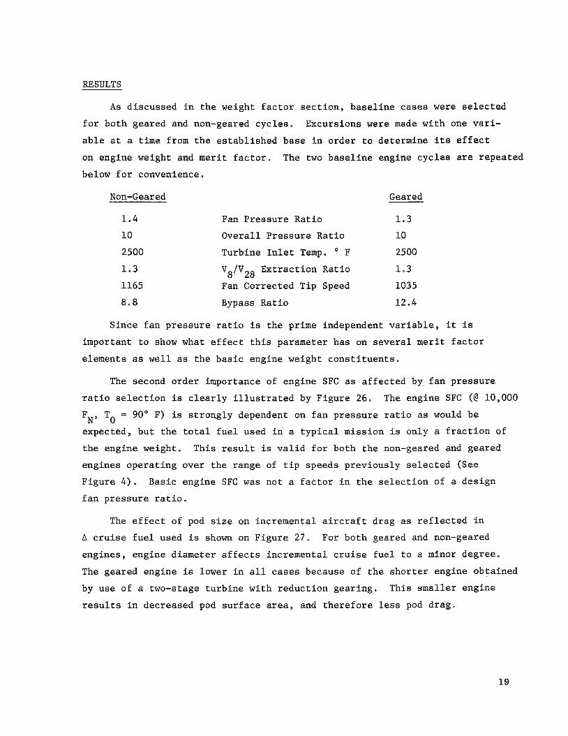
A s discussed i n t h e weight f a c t o r s e c t i o n , b a s e l i n e cases were s e l e c t e d
f o r both geared and non-geared cycles.
a b l e a t a t i m e from t h e e s t ab l i shed base i n order t o determine i t s e f f e c t
on engine weight and merit f a c t o r .
below f o r convenience.
Excursions were made wi th one vari-
The two b a s e l i n e engine cyc lee are repea ted
Non-Geared
1 .4
10
2500
1.3
1165
8,8
Geared
Fan P res su re Rat io 1.3
Overa l l P re s su re Rat io 10
Turbine I n l e t Temp. O F 2500
'8"28 Fan Corrected Tip Speed 1035
Bypass Rat io 12.4
Ex t rac t ion Rat io 1.3
Since f a n p res su re r a t i o is the prime independent v a r i a b l e , it is
important t o show what e f f e c t t h i s parameter has on several merit f a c t o r
elements as w e l l as t h e b a s i c engine weight c o n s t i t u e n t s .
The second order importance of engine SFC as a f f e c t e d by f a n p res su re
r a t i o s e l e c t i o n is c l e a r l y i l l u s t r a t e d by Figure 26.
FN, To = 90" F) is s t rong ly dependent on f an p res su re r a t i o as would be
expected, bu t t h e t o t a l f u e l used i n a t y p i c a l mission i s only a f r a c t i o n of
t he engine weight. This r e s u l t i s v a l i d f o r both t h e non-geared and geared
engines ope ra t ing over t h e range of t i p speeds prev ious ly s e l e c t e d (See
F igure 4 ) . Basic engine SFC w a s no t a f a c t o r i n t h e s e l e c t i o n of a des ign
f a n p res su re r a t i o .
The engine SFC (@ 10,000
The e f f e c t of pod s i z e on incremental a i r c r a f t drag as r e f l e c t e d i n
A c r u i s e f u e l used i s shown on Figure 27. For both geared and non-geared
engines , engine diameter a f f e c t s incremental c r u i s e f u e l t o a minor degree.
The geared engine is lower i n a l l cases because of t h e s h o r t e r engine obtained
by use of a two-stage t u r b i n e wi th r educ t ion gear ing . This smaller engine
r e s u l t s i n decreased pod s u r f a c e area, and t h e r e f o r e less pod drag .
19

The effect of f an p re s su re r a t i o on fan t i p diameter is shown on
Figure 28. While having a r e l a t i v e l y s m a l l e f f e c t on A c r u i s e f u e l , engine
diameter and length are shown on Figure 29 t o have a very major impact on
engine pod weight. The design of t h e pod s t r u c t u r a l e lements , s k i n , and
i n l e t and exhaust doors and a c t u a t i o n systems are going t o b e very s t r o n g l y
a f f ec t ed by engine volume. A nominal va lue of 2.7 l b s / f t of s u r f a c e area
was used i n t h i s s tudy . The e f f e c t of fan p re s su re r a t i o on pod s i z e is
most c l e a r l y i l l u s t r a t e d by Figure 12. Geared fan pod weight is less than
non-geared f o r t h e same fan p res su re r a t i o because of reduced pod depth
brought about by t h e s h o r t e r geared engine. A conclusion he re would b e
t h a t i f low fan p res su re r a t i o were s e l e c t e d f o r purposes o f , say , very low
n o i s e , every approach must b e exhausted t o achieve minimum engine l eng th
t o minimize engine volume.
2
F igures 30 and 31 i l l u s t r a t e t h e con t r ibu t ion of non-geared and geared
engine component weights t o t h e t o t a l engine weights as a func t ion of fan
p re s su re r a t i o . Examination of t h e s e curves i n d i c a t e s t h a t f o r t h e range
of p re s su re r a t i o covered as excursions from t h e b a s e l i n e cases, t h a t engine
weight is r e l a t i v e l y cons tan t due t o the counter a c t i n g e f f e c t s of weight
changes i n t h e low and high p res su re spoo l s , where a l i g h t e r fan i s o f f s e t
by a l a r g e r s i z e core engine. It must be remembered t h a t a l l of t h e s e d a t a
t h u s f a r d i scussed have been generated a t a cons tan t t u r b i n e i n l e t temperature
2500" F.
T o t a l weight f a c t o r c o n s t i t u e n t s t h a t is, engine, pod and f u e l weight
f o r bo th b a s e l i n e engines are shown on Figure 32 , as a func t ion of fan
p re s su re r a t i o f o r t h e moderate t i p speed schedule.
geared curve l abe led t h i r d (3rd) s p l i t t e r i s shown t o achieve equal no i se
suppression. The t h i r d s p l i t t e r i s requi red because of the sho r tnes s of
t h e geared engine duct . Engine weight and pod weight are c l e a r l y t h e areas
of i n t e r e s t i n improving o v e r a l l weight f a c t o r . The weight f a c t o r e lements
of A c r u i s e f u e l , l i f t f u e l , and a c o u s t i c t rea tment w i l l n o t y i e l d s u b s t a n t i a l
reduct ions . I n terms of o v e r a l l t o t a l weight f a c t o r , optimum fan p res su re
r a t i o appears t o be between 1.35 and 1.45 f o r t h e non-geared engine , and
between 1.3 and 1.4 f o r t h e geared engine.
The top band on t h e
20

The e f f e c t of varying f a n t i p speed is shown on Figures 33 and 34 f o r
non-geared and geared engines r e spec t ive ly . For a non-geared, h igher t i p
speeds inc rease b a s i c engine weight, b u t r e s u l t i n fewer low p res su re
tu rb ine s t a g e s , making a s h o r t e r engine wi th i ts saving i n pod weight,
t rend becomes inc reas ing ly apparent a t t h e lowest f a n p re s su re ( 1 , 3 ) i n v e s t i -
gated. I n the case of t h e geared engine, of course t h i s is not t h e case,
s i n c e we are dea l ing wi th a cons tan t number of low p res su re t u r b i n e s t a g e s ,
A t t h e lowest p re s su re r a t i o i n v e s t i g a t e d (1.2) however, gear s i z e and
weight begin t o have an e f f e c t on engine weight and f an diameter because
of t he increased s i z e and weight of t h e reduct ion gear (see Figure 2)
needed t o achieve the requi red speed r a t i o between t h e low p res su re t u r b i n e
and f a n spool .
The s o l i d d o t s on these f i g u r e s and those which fo l low i n d i c a t e t h e l o c a t i o n
of t h e b a s e l i n e cyc le po in t w i th in the mat r ix of da t a .
on F igure 36 l abe led LPT Y = 2.0 j u s t below the b a s e l i n e case ind ica t ed P
t h e advantage t o be obtained from use of a more h igh ly loaded low p res su re
t u r b i n e than t h e nominal va lue of Z 1 . 7 . The use of t h i s more h ighly
loaded t u r b i n e r e s u l t e d i n reducing t h e number of s t a g e s from 4 t o 3 .
r e s u l t i n g l i g h t e r and s h o r t e r engine y i e l d s t h e ind ica t ed improvement i n
weight f a c t o r , and p o i n t s toward a probable d i r e c t i o n of increased b e n e f i t f o r
t h e d i r e c t d r i v e approach.
This
Cons t i t uen t s f o r t hese graphs are shown on Figures 35 and 36.
The d a t a poin t
The
It would be expected t h a t t u r b i n e i n l e t temperature would have a major
impact on t o t a l weight f a c t o r due t o a h igher t u r b i n e i n l e t temperature
r e s u l t i n g i n a smaller l i g h t e r core engine, up t o t h e po in t where the need
f o r excess ive cool ing a i r reduces any advantage i n f u r t h e r i nc reas ing temper-
a t u r e . F igures 37 and 38 show t h e e f f e c t of t u r b i n e i n l e t temperature and
o v e r a l l c y c l e p re s su re r a t i o on t o t a l weight ( m e r i t ) f a c t o r f o r non-geared
and geared engines. Strong t r ends i n d i c a t e t h a t f o r a non-geared engine ad-
vantages of increased T
r a t i o beyond 10/19 a choice of T
system may w e l l be d i c t a t e d by cons ide ra t ions of s i m p l i c i t y inhe ren t i n a
moderate T and a small number of compressor s t a g e s , In t h e case of the
s t i l l e x i s t i n g beyond 2500" F and cyc le p re s su re 4 and c y c l e p re s su re r a t i o i n t h e non-geared 4
4
21

geared fan , l i t t l e advantage i n o v e r a l l weight f a c t o r is obtained above
2400" F and o v e r a l l p re s su re r a t i o of 10/1 because of i nc reas ing gear weight
and r e l a t i v e l y cons tan t engine length . Comparison of t he two curves w i l l
i n d i c a t e t h a t t h e non-geared engine has g r e a t e r p o t e n t i a l f o r b e t t e r weight
f a c t o r than t h e geared engine e
The f i n a l engine parameter which w a s i n v e s t i g a t e d w a s V /V e x t r a c t i o n 8 28' r a t i o . Figure 39 i n d i c a t e s t h a t small v a r i a t i o n s around t h e b a s e l i n e value
y i e l d a p r e d i c t a b l e t rend . In any event , e x t r a c t i o n level w i l l very l i k e l y ,
i n t h e f i n a l a n a l y s i s , b e e s t a b l i s h e d by a c o u s t i c requirements (see Figure 1 8 )
I n o rde r t o a s su re t h a t t h e r e s u l t s were no t b i a s e d unduly by t h e mission
assumptions, t h e weight f a c t o r s of t h e b a s e l i n e engines were generated us ing
t h e a l t e r n a t e missions and a l t e r n a t e a i r p l a n e s descr ibed i n t h e weight f a c t o r
s e c t i o n . The r e s u l t s of t h e a n a l y s i s are descr ibed on Figures 40, 4 1 , 42 and
4 3 . Examination of t h e s e curves i n d i c a t e t h a t t h e range of t h e primary design
parameter t o b e s e l e c t e d (fan p res su re r a t i o ) i s not a t a l l a f f e c t e d by t h e s e
d i f f e r e n t mission assumptions.
Figures 44 and 45 are summary c h a r t s showing c ross hatched areas having
t h e p o t e n t i a l t o meet t h e s t a t e d n o i s e requirements. A s can b e seen on t h e
c h a r t s , t h e b e s t engine meeting t h e n o i s e requirements appears t o b e a non-geared
design with a fan pressure r a t i o of 1 . 3 t o 1.35 and a t u r b i n e i n l e t temperature
of 2500 t o 2700" F.
wi th a non-geared engine except when t h e non-geared engine is designed f o r
low t u r b i n e i n l e t temperatures . Geared engine designs were dropped from f u r t h e r
cons idera t ion at t h i s p o i n t f o r t h e fol lowing reasons:
I n t h e case of t h e geared design, i t is no t compet i t ive
no n o i s e advantage over d i r e c t d r i v e
h i g h e r development r i s k than d i r e c t d r i v e due t o advanced tech-
nology gear ing requi red @
Considerat ion w a s thereby narrowed t o two regions:
22

Low T4 Moderate T4
1800- 2000 Tqe F 2 500- 2600
1'2-1.25 Fan Pressure Ra t io 1.25-1.3
6- 8 Core Pressure Ra t io 10
1.2-1,3
1000-1200
3
% 95
* 90
% 2
Q8/Q2 8 U,/J-Fi
1.2-1.3
1100-1400
No. Fan Turblrie Stages 3-4
PNdB @ 8,000 l b
PNdB @ 10,080 l b . Q 98
%I 95
LPT $p 2-2 5
on of h i g h e r t u r b i n e 16 g i n a l l y s e l c e t c d f o r t h e
seudy is suppartad &vera1 rcmoirio: The 1
with t h e h ighe r t u loaditig (2 to 2b!3 co does n o t have an iBpar
is d r e l a t i v e l y m a l l f r e e t i o n e€ the to ta l weight f ag to r .
that &nd &ib@lic i ty deinand a@ ttl tbirie stages &IB p s ~ i s l b l e . Th i s
e f f e c t is Shown on f i g w e 46 where incfe&@$d Ladding can fcsult i n 1 to i! sfAg@g:,
t e f f e c t on a v e r a l l w@f$ht €ac to r siiwe l i f t h e 1 used
The rcalizatfon
saving Of fh@g&z ua'virlgl $I% r e f l e e t a d %a figuree 47 afld 48 which show
i n e wei$ht arid t o t a l weight f$e&ar advasttages which dr@ ava f l ab fe
to Wo typiedf cyal@@ i a th@ region df g t . F i n a l l y , NASA
of h igh ly load
wi th suf E i c i e n t mam@fizm eo Bssure t h t h e r i s k s wigh
w6tlld B6f b@ &ifidti@
compactness also l e d t o t h e recofmnendation of a more advanced
h ighe r loadin&, t i p lp@ed and a x i a l vel
.%I engZne of t h e 1
L, STOL, md & airerafk rombitied wi th cons ide ra t ions of probable
l i f e Gngine opera t ia f ia l edures l e d , a t t h i s p o i n t , t o r ev i sed d
n t s , p a r t i c u l a r l y i n t h e area of no i se . The new requirements are
l i s t e d below, wi th fht? o r i g i n a l l i s t e d as r e fe rence .

Orig ina l Revised
10,000 l b . Maximum t h r u s t 90" day 12,500 l b . - Noise Rat ing t h r u s t 10,000 l b
< 95 f o r 1 engine @ 500' s i d e l i n e PNdB < 100 f o r 12 engines @ 10,000 l b 10,000 lb .
11,000 l b . Engine ou t emergency 13,000 l b .
The e f f e c t of t h e r ev i sed n o i s e requirements is very s u b s t a n t i a l
s i n c e t h e equ iva len t s i n g l e engine no i se t a r g e t is now approximately 88
relative t o an o r i g i n a l requirement of 9 5 . In add i t ion , i t w a s r equ i r ed t o
b e t t e r t h e < 100 t a r g e t by as wide a margin as poss ib l e , hopefu l ly i n t h e
range of 4 o r 5 PNdB.
ADDIT IONAL RESULTS
Noise d a t a were recomputed us ing the rev ised engine s i z e and n o i s e r a t i n g
p o i n t criteria. Noise c o n s t i t u e n t s as a func t ion of fan p res su re r a t i o are
shown on Figure 49 . The f an j e t n o i s e w a s computed by two methods, bo th of
which are shown.
wi th a l i n e a r log-log e x t r a p o l a t i o n below 1000 f e e t / s e c .
The SAE p r e d i c t i o n is based on t h e s tandard SAE method
The modified f an jet method is based on co ld jet n o i s e d a t a supp l i ed by
NASA - L e w i s . These d a t a i n d i c a t e t h a t a c t u a l no i se w i l l be i n the range
3 t o 4 PNdB lower than t h a t computed by t h e e x t r a p o l a t i o n of t h e s tandard SAE
method. Note t h a t f o r t h e da t a shown h e r e t h e fan r equ i r e s two s p l i t t e r s p l u s
5 PNdB source n o i s e reduct ion wh i l e t he t u r b i n e r equ i r e s 2 s p l i t t e r s . T o t a l
n o i s e generated is shown on Figure 50 f o r two levels of fan suppress ion . With
t h e use of two s p l i t t e r s t h e ob jec t ive l e v e l cannot b e m e t a t any fan p res su re
r a t i o w i t h i n t h e range of t h e i n v e s t i g a t i o n . Three s p l i t t e r s p lus A5 PNdB
source r educ t ion are r equ i r ed t o achieve < 100 PNdB. A fan design p res su re
r a t i o of 1 .3 is as high as i t is p o s s i b l e t o set wi thout exceeding t h e 100
PNdB l i m i t , and t h i s w i t h no margin. Reducing fan design p res su re r a t i o down
t o 1.2 r e s u l t s i n a n o i s e of about 95 PNdB. Noise requirements have thus
e s t a b l i s h e d a maximum design fan p res su re r a t i o of 1.3.
Engine b a r e weight and engine weight f a c t o r s are shown on Figures 51* and
52* f o r t h e cyc le s of i n t e r e s t . Resul t s are gene ra l ly similar t o those using
* Resu l t s shown he re are f o r engine having 25 percent more t h r u s t than engine descr ibed up t o and inc luding Figure 4 5 ,
24

t h e o r i g i n a l design requirements , t h e 1 . 3 fan p res su re r a t i o design wi th t h e
h ighes t T y i e l d s t h e lowest ba re engine weight and t h e b e s t t o t a l weight
f a c t o r . For t h e low T des igns , very l i t t l e d i f f e r e n c e e x i s t s i n t h e f a c t o r s
between €an p res su re r a t i o of 1 .2 and 1.25. The t r end f o r bo th , however,
i n d i c a t e s t h a t i nc reas ing T 4 r e s u l t s i n s u b s t a n t i a l improvements i n bo th
weight and weight f a c t o r . With t h e s e d a t a a v a i l a b l e , t h e s t a g e i s thus
set f o r s e l e c t i o n of t h e s p e c i f i c engines f o r use i n t h e component (Task 11)
and engine layout (Task 111) phases of t h e pre l iminary design s tudy.
4
4
RECOMMENDATIONS FOR TASKS II/III
From t h e o u t s e t of t h e d e l i b e r a t i o n s on engine s e l e c t i o n i t w a s clear
t h a t two main branches might b e p r o f i t a b l y inves t iga t ed . One approach j u s t
meeting t h e n o i s e requirements w i t h t h e lowest engine weight and b e s t t o t a l
weight f a c t o r , and another meeting t h e n o i s e requirements wi th a wide margin,
wi th not as a t t ract ive a weight , b u t having a low t u r b i n e i n l e t temperature
and an uncooled fan tu rb ine . I m p l i c i t i n t h i s approach is t h a t t h e lower
temperature engine wi th the lower n o i s e r ep resen t s a lower r i s k des ign ,
p a r t i c u l a r l y wi th regard t o no i se .
f o r t h e l i gh twe igh t engine is n o t , however, considered t o be an i t e m of r i s k
s i n c e cu r ren t commerical t r a n s p o r t engines ope ra t e i n t h i s range, and t h e
l i f t engine i s planned f o r use i n t h e 1980's.
The t u r b i n e i n l e t temperature s e l e c t e d
The l igh tweight engine recommended w a s as fol lows:
bypass r a t i o 12.6
fan p res su re r a t i o 1 .25
fan co r rec t ed t i p speed 1180
o v e r a l l p re s su re r a t i o 1 0 / 1
t u r b i n e i n l e t temperature 2500' F
No. HP t u r b i n e s t a g e s
No. LP t u r b i n e s t a g e s
1
3
average LP t u r b i n e loading 2.5
e x t r a c t i o n V8/V28 1 .3
25

I n t h i s case, t h e 1.25 fan pressure r a t i o w a s s e l e c t e d t o provide a
s m a l l n o i s e margin relative t o t h e maximum value of 1 .3 (see Figure 50).
The more conserva t ive engine recommended w a s as fol lows:
bypass r a t i o 11.6
fan p res su re r a t i o
f an co r rec t ed t i p speed
1 .2
1060
o v e r a l l p re s su re r a t i o 7
8 t u r b i n e i n l e t temperature 2000" F
e No. HP t u r b i n e s t a g e s 1
c l ~ No. LP t u r b i n e s t a g e s 3
I, average LP t u r b i n e loading 2 .o
e e x t r a c t i o n v8/V28 1 .3
The method of s e l e c t i o n of level of t u r b i n e i n l e t temperature i s shown
on Figure 53, is p o s s i b l e t o go wi thout needing t o begin cool ing t h e low p res su re system.
A t u r b i n e i n l e t temperature of nea r 2000" F i s as f a r as i t
I n o rde r t o more thoroughly i n v e s t i g a t e t h e p o t e n t i a l of t i p speeds
below 1000 f ee t l s econd , which some i n v e s t i g a t o r s b e l i e v e w i l l produce sub-
s t a n t i a l n o i s e reduct ion , i t was recommended t h a t a t h i r d design b e undertaken,
e s s e n t i a l l y a modi f ica t ion of t h e low T 4 approach.
bypass r a t i o 11.6
fan pres su re r a t i o 1 .2
f an co r rec t ed t i p speed 855
o v e r a l l p re s su re r a t i o 7
t u r b i n e i n l e t temperature 2000' F
No. HP t u r b i n e s t a g e s 1
No, LP t u r b i n e s t ages 4
average LP t u r b i n e loading 2.2
e x t r a c t i o n V /V 1 .3 8 28
26

Tip speed of t h i s t h i r d engine w a s set wi th regard t o achieving a
subsonic relative t i p v e l o c i t y at t h e n o i s e r a t i n g p o i n t , and l i m i t i n g the
number of fan t u r b i n e s t a g e s t o 4 with average loading less than 2.5. Qbjec-
t i v e fan design s t a l l marg-in i s t o be t h e same.
These t h r e e designs were mutually recommended and approved f o r t h e
Task I1 and Task I11 work of component design and engine layout , d e t a i l e d
acous t i c and performance eva lua t ion , and engine weights.
27

TASK I1
SELECTED ENGINE CHARACTERISTICS
Component Parameters
The fol lowing component design parameters were e s t a b l i s h e d f o r Task 11.
Engine
F l a t Rated Thrust t o 90" F
Bypass Ra t io
Fan P r e s s u r e Ra t io /UT6-
Fan Bypass Corrected Airflow
Fan S t a l l Margin
Number of Compressor Stages
Core P r e s s u r e R a t i o / U T / K
Core Corrected Airflow
Core S t a l l Margin
T4 " F 90" Day
Number HP Turbine Stages
Number LP Turbine Stages
Margins
ILFlAl
12,500
12.6
1.25/1180
590
18%
5
10/1390
44.9
18%
2500
1
3
ILF2A1
12,500
11.6
1.2/1060
656
18%
4
?/1410
54.4
18%
2000
1
3
ILF2A2
12 500
11.6
1 e 21855
656
18%
4
7/1430
54.4
18%
2000
1
4
Turbine i n l e t temperature margin i s e s t a b l i s h e d a t 110" F f o r ILF2A1 and
ILF2A2 and 135" F f o r ILFlAl.
everywhere.
A t h r e e percent f u e l f low margin is app l i ed
The gene ra l arrangement of t h e components w i l l be c o n s i s t e n t w i th 0.65 i n l e t
r ad ius r a t i o compressor and s p l i t flow fan shown on Figure 54.
28

MATERIALS SELECTION
S e l e c t i o n Criteria
The materials and processes s e l e c t e d f o r t he ILF engine are s ta te-of- the-
a r t materials f o r many components s i n c e cos t is a major design cr i ter ia .
However, some component requirements d i c t a t e d t h e use of more advanced materials
t o m e e t t h e equa l ly important design cr i ter ia of weight. An a l l important con-
s i d e r a t i o n is r e l i a b i l i t y and t h e method of a t t a i n i n g t h i s r e l i a b i l i t y w i th t h e
materials and processes chosen is a p a r t of t h e fol lowing materials s e l e c t i o n
d iscuss ion .
Light materials, aluminum, t i t an ium, and composites are s p e c i f i e d f o r t h e
f a n , f an frame,fan duc t , compressor spool and forward compressor case and blading.
Advanced h igh s t r e n g t h n i c k e l base allows are used i n the t u r b i n e r o t o r t o
reduce weight .
combined wi th l i g h t weight cases t o become s t r u c t u r a l members of t he engine.
All sound suppress ion panels are l igh tweight honeycomb s t r u c t u r e s
Major engine p a r t s and t h e i r material , coa t ing (where a p p l i c a b l e ) , spec i -
f i c a t i o n and material form are shown on Table V I I .
Advanced a l l o y s assumed f o r use r ep resen t byproducts of t h e cont inuing
e f f o r t s by General E l e c t r i c t o develop materials and processes t o meet t h e
requirements f o r f u t u r e engine programs.
Material Forecas ts
The p r a c t i c e of f o r e c a s t i n g s t r u c t u r a l materials f o r a i r c r a f t engines t h a t
would be a v a i l a b l e during t h e fol lowing four t o f i v e year t i m e per iod w a s begun
i n 1961.
These f o r e c a s t s w e r e made as materials d a t a curves and were f i r s t used i n
prel iminary des ign of t h e GE4 engine f o r t he supersonic t r a n s p o r t . These fore-
casts, o r goa ls , then developed i n t o major materials programs a t General E lec t r ic
and l e d t o t h e t imely i n t r o d u c t i o n of new, advanced materials. An example of
t h e success General Electric has experienced wi th t h i s approach is shown below:
29

O r i g i n a l
Designation General ized Goal f o r '67-'70 A v a i l a b i l i t y
X1600 Shee t , 1600-1800F St ronger than Has te l loy X
X1800 Sheet,, 50F R41, 1600-1800 F
x1900 Forged Bucket 50F Udimet 700 Forged
x2000 Shee t , 1800-2200F Appl ica t ions
Ni7OXD Discs, 800-1200F, S t ronger than IN718
Ni69XB Cast Buckets, 50F U700 Cast
Ti9OOX Discs/Blades, 2X s t r e n g t h of T i 6-2-4-2
1972 - 1975 Forecas t Goals
Alloy Now Avai lab le
HS188
Ren6 63
Ren6 85
T D N i ch rome
R e d 95
Ren6 80
T i 562 1s
General ized goa ls f o r 1972-1975 materials used i n t h e p re sen t pre l iminary
designs are shown below:
O r i g i n a l
Designat ion General ized Goals Year Avai lab le
Ni72XB N i a l l o y f o r b lades and vanes improved over 1972
Rent5 80 - now c a l l e d Ren& 120 - i n product ion
s c a l e up phase.
Ti72W T i a l l o y f o r b lades and d i s c s , h ighe r t e n s i l e 1972
and f a t i g u e over T i 6-4. Now c a l l e d Ren6 17..
Ti75XD T i a l l o y f o r h igh s t r e n g t h d i s c s . 1975
Ni76XB Disc a l l o y wi th h ighe r s t r e n g t h over Ren& 95 1975
Gr/Pi72XB A 450" F graphi te /epoxy lamina te f o r b l ades , 1972
vanes and frames e
Addi t iona l Considerat ions
The proper s e l e c t i o n of materials f o r a des ign evolves from s t u d i e s invol-
v ing t r a d e o f f s among d i v e r s e requirements inc luding common s t r e n g t h des ign
c r i t e r i a such as 0.2% y i e l d s t r e n g t h and 0.2% p l a s t i c c reep s t r e n g t h , e f f e c t s
of environment (oxida t ion , ho t co r ros ion , and eros ion) and f a c t o r s governing
30
cyclic life such as low and high cycle fatigue strengths; ductility, and resis-
tance to crack propagation. weight evaluations for material selections. Influence is also felt from other
factors such as producibility, maintainability and reliability.
All of these criteria are factored into cost and
Sufficient knowledge about the scatter of design (property) data must be available so that statistical minumums may be established. These minimum property
levels must be integrated with material specifications. dence level in these design data comes from carefully controlled testing of specimens machined from components (forgings, castings or sheet) that have
experienced representative material and processing histories.
The necessary confi-
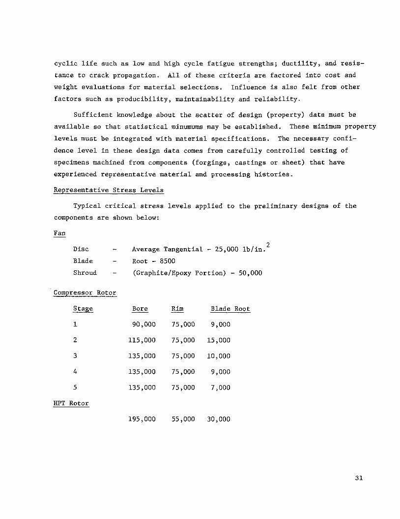
Representative Stress Levels
Typical critical stress levels applied to the preliminary designs of the components are shown below:
Fan - 2 Disc - Average Tangential - 25,000 lb/in.
Blade - Root - 8500 Shroud - (Graphite/Epoxy Portion) - 50,000
ComDressor Rotor
Stage
1
2
3
4
5
Bore - Rim Blade Root
90,000 75,000 9,000
115,000 75,000 15,000
135 000 75 000 10 000
135,000 75,000 9,000
135,000 75,000 7,000
HPT Rotor
195 000 55 000 30 000
31

LPT Rotor
Kim - Bore - Stage
1 80 000 65,000
2 80,000 65,000
3 80 ., 000 70 000
4 80,000 70 000
Fan Shaft
Blade Root
5 000
7 000
10,000
10 9 000
2 60,000 lb/in. S
6
Combustor Outer Casing 2 40,000 lb/in,
FAN AND COMPRESSOR DESIGN
Preliminary mission and cycle performance analyses specified the pressure
ratio and flow of the fan and compressor components for the ILFlAl and ILF2A1. Fan tip speeds were determined through cycle, acoustic and low pressure turbine
design requirements. With these parameters fixed as a starting point, the fan
and compressor flowpath and blading were designed which are most attractive in the total engine flqwpath configurations.
The ILF2A2 fan is proposed to demonstrate a noise reduction associated with reducing fan tip speed while maintaining performance.
and flow are to be the same as ILF2A1 and the compressor will be the same as in
the ILF2A1. Tip speed and flowpath configurations are to be determined which
best complement the total engine configuration.
Fan pressure ratio
Experience with distortion levels and general engine operating requirements
indicates that 18 percent constant speed stall margin will be sufficient for both the fan and compressor components.
to be greater than in a conventional application since the engine will be installed
vertically resulting in inlet crossflows during transition, Engine vectoring,
however, will tend to reduce the cross flow effects and inlet distortions toward typical subsonic engine levels such that the engines will run stably with con-
tinued thrust s
Inlet distortion levels are expected
32

Since cyc le a n a l y s i s i nd ica t ed l i t t l e overspeed requirement, t h e des ign
s p e c i f i c flow f o r both f a n and compressor were made high t o minimize machine
s i z e .
f o r f an and compressor, r e spec t ive ly .
wi th General Electric experience t o y i e l d good component e f f i c i e n c i e s ,
2
These s p e c i f i c flow levels are c o n s i s t e n t
The s p e c i f i c flow va lues s e l e c t e d are 42.5 l b / s e c - f t 2 and 40.0 l b / sec - f t
Parametr ic s t u d i e s were then made t o determine t h e b e s t component confi-
gu ra t ion c o n s i s t e n t wi th aerodynamic, a c o u s t i c and engine conf igu ra t ion
requirements. The des ign ob jec t ives t h a t have been e s t ab l i shed are summarized
below.
Fan Aerodynamic Design
The f a n des ign requirements f o r t h i s s tudy are very similar t o t h e f irst
s t a g e of t h e TF39, an e x i s t i n g developed f a n s t a g e , designed f o r a p res su re r a t i o
of 1.25 and a t i p speed of 1100 f t / s e c .
VTOL f a n s and t h e TF39 s t a g e are compared i n Table V I I I . This s i m i l a r i t y i n
des ign performance a l lows t h e use of t h e TF39 f i r s t s t a g e d a t a as a base f o r
determining t h e s t a l l p re s su re rise and des ign po in t e f f i c i e n c y of VTOL fans .
S i g n i f i c a n t design parameters of t h e
S t a l l test r e s u l t s f o r s t a g e 1 of t h e TF39 f a n d e f i n e t h e peak p res su re
rise t h a t can be achieved a t t h a t speed, a spec t r a t i o , and s o l i d i t y . A s t a l l
c o r r e l a t i o n procedure developed by General Electr ic , which relates s o l i d i t y ,
a spec t r a t i o and v e c t o r diagrams, permi ts t h e des igner t o p r e d i c t t h e peak pres-
s u r e rise c a p a b i l i t y of a new des ign by r e l a t i n g t o t h e demonstrated performance
of a s i m i l a r e x i s t i n g machine. This c o r r e l a t i o n , t h e r e f o r e , can be used t o make
t r a d e o f f s i n speed and a spec t r a t i o f o r example, f o r a requi red s t a l l margin,
The above procedure w a s appl ied t o Fans I L F l A l and ILF2A1 t o relate r o t o r
Resul t s of t h e s tudy are aspec t r a t i o a g a i n s t s t a l l margin f o r a given speed.
shown i n F igure 55. Blade and vane a spec t r a t i o s w e r e s e l e c t e d t o keep essent -
i a l l y a cons t an t b lade t o vane r a t i o of 0.5 wi th r o t o r and OGV p i t c h l i n e
s o l i d i t i e s he ld cons t an t . The s tudy shows t h a t ILFlAl and ILF2A1 fans w i l l have
18% o r g r e a t e r cons tan t speed s t a l l margin a t r o t o r a spec t r a t i o s of 3.9 and
3.2, r e s p e c t i v e l y .
A similar paramet r ic s tudy w a s conducted f o r t h e ILF2A2 f a n wi th except ion
of t i p speed being a v a r i a b l e , not a f i x e d parameter , The r e s u l t s of t h e s tudy
( see F igure 56) were used i n conjunct ion wi th aeromechanical, a c o u s t i c a l , and
low p res su re t u r b i n e requirements t o set t h e t i p speed a t 855 f t / s e c and r o t o r
a spec t r a t i o a t 2.9. 33

The f i n a l f lowpath and vec to r diagrams were determined wi th t h e Compressor
Axisymmetric Flow Determination program descr ibed i n NASA CR5458. S ince t h i s
s tudy is a pre l iminary des ign , d e t a i l s of t h e design were s impl i f i ed where end
r e s u l t s are no t c r i t i c a l t o t h e o b j e c t i v e f o r t h i s s tudy . I n t h e axisymmetric
a n a l y s i s , only b l ade row edge s t a t i o n s and several f r e e space s t a t i o n s between
t h e r o t o r and o u t l e t guide vane were ass igned . S imi l a r ly t h e o u t l e t guide vane
w a s t r e a t e d as a r a d i c a l vane al though i t w i l l be t i l t e d a x i a l l y and circumferen-
t i a l l y f o r a c o u s t i c a l reasons i n t h e f i n a l design. Experience with o t h e r t i l t e d
des igns show t h a t average b l ade loadings w i l l no t be s i g n i f i c a n t l y changed.
Cross s e c t i o n s of t h e ILFlA1, ILF2A1, and ILF2A2 flow pa ths are shown i n
F igures 57, 58, and 59, r e spec t ive ly . The f a n c o n s i s t s of t h e b lade above t h e
flow s p l i t t e r .
t i o n s r e q u i r i n g minimum 2 b lade chords a t t h e t i p and 1 blade chord a t t h e hub,
Annulus area d i s t r i b u t i o n s are i d e n t i c a l w i th t h e peak p res su re rise p red ic t ions .
Axisymmetric c a l c u l a t i o n s do not cons ider t h e s t rong v iscous and t h r e e dimen-
s i o n a l f low e f f e c t s on an e x p l i c i t b a s i s . They are handled i n p a r t through
assessment of a n e f f e c t i v e area c o e f f i c i e n t which is d i s t r i b u t e d uniformly over
t h e annulus. Based on f a n des ign experience the c o e f f i c i e n t va lues used are
0.98 a t t h e r o t o r i n l e t , 0.96 a t r o t o r d i scharge and OGV i n l e t , and 0.95 a t OGV.
T h e v e c t o r diagrams f o r t h e ILFlAl, ILF2A1 and ILF2A2 f a n s are summarized i n
Tables I X , X , X I , r e spec t ive ly .
Spacing of t h e o u t l e t guide vane was made on a c o u s t i c considera-
Examination of t h e b lade and vane loadings i n d i c a t e t h a t a h igher des ign
p res su re r a t i o could be achieved a t these t i p speeds which were set by low pres-
s u r e t u r b i n e and/or a c o u s t i c requirements.
capable of d e l i v e r i n g t h e average f an p res su re r a t i o .
A s a r e s u l t t h e f an r o t o r hub is
For pre l iminary des ign
purposes , i t w a s assumed t h a t t he r a d i a l t o t a l p re s su re p r o f i l e w a s cons tan t a t
s t a g e d ischarge .
g rad ien t t o r e d i s t r u i b u t e b l ade loadings . The l o s s c o e f f i c i e n t s are i n gene ra l
agreement wi th t h e NASA c o r r e l a t i o n s wi th modi f ica t ions based on experience and
t h e i r level is c o n s i s t e n t wi th t h e o b j e c t i v e o v e r a l l e f f i c i e n c y .
A f i n a l des ign may poss ib ly inco rpora t e some r a d i a l p re s su re
Fan performance maps f o r ILFlA1, ILF2A1, and ILF2A2 are based on t h e TF39
s t a g e 1 measured performance. The es t imated performance maps are shown i n
34

Figures 60, 61, and 62 f o r ILFlA1, ILF2A1, and ILF2A2, r e spec t ive ly . Design
e f f i c i e n c i e s are es t imated based on t h e TF39 f i r s t s t a g e fan. Relative t o t h e
TF39, e f f i c i e n c y d i f f e r e n c e s due t o lower OGV loadings , t i p speed , h ighe r s p e c i f i c
flow, t i p shroud, r o t o r OGV f r e e space, and sound t reatment were accounted f o r .
The sum of t h e s e d i f f e r e n c e s r e s u l t i n design e f f i c i e n c i e s of 87.0% f o r ILFlA1,
87.6% f o r ILF2A1, and 88.2% f o r ILF2A2.
Design of the b lad ing elements was performed along axisymmetric stream
s u r f a c e s us ing t h e p r o j e c t i o n recommended i n Vol. 85, Series D, ASME Trans-
a c t i o n s . This p r o j e c t i o n c u t s t h e b lades along axisymmetric s u r f a c e s b u t views
t h e cut s e c t i o n s along the b lade a x i s (blade axis f o r t hese des igns is a r a d i a l
l i n e ) . The inc idence and d e v i a t i o n angles are def ined i n t h i s "cascade projec-
t ion" and are c a l l e d cascade angles .
Blading is s e l e c t e d based on the i n l e t Mach number of t h e s t r e a m l i n e sec-
t i o n s . I f t h e i n l e t Mach number is about 0 , 9 and above, t h e a i r f o i l w i l l have
s p e c i a l meanline t o minimize t h e shock Mach number but have s u f f i c i e n t t h r o a t
area margin t o pass the flow. Thus, t h e t i p s e c t i o n s of t h e r o t o r s w i l l be
s p e c i a l a i r f o i l s wh i l e t he i n n e r s e c t i o n s may be double c i r c u l a r arc.
o u t l e t guide vanes, the i n l e t Mach number is s u f f i c i e n t l y low (2 0.8) and t h e
65 series th i ckness on a c i r c u l a r a r c mean l i n e w i l l be used.
For t h e
Incidences s e l e c t e d f o r t h e r o t o r t i p reg ion are es t imated t o y i e l d t h e
c o r r e c t flow alignment wi th the s u c t i o n s u r f a c e .
on low speed cascade d a t a .
t i o n r u l e . When changes i n r ad ius and a x i a l v e l o c i t y are p resen t a long a stream-
l i n e , t h e d e v i a t i o n angle is based on t h e camber of an equ iva len t two-dimensional
cascade having t h e same c f r c u l a t i o n . Occasional ly , an empi r i ca l adjustment
X f g is used t o provide an adjustment on Carter's d e v i a t i o n , based on exper ience ,
Incidence, t o t a l d e v i a t i o n , and X d i s t r i b u t i o n s of both r o t o r s and s t a t o r s are
shown i n Tables I X , X, and X I .
A l l o t h e r inc idences are based
T r a i l i n g edge angles are set us ing Carter's devia-
f
Supercharger Aerodynamic Design
The co re supercharging s t a g e of a l l t h e engines is t h e hub s e c t i o n o€ the
f a n r o t o r below t h e flow s p l i t t e r . It is , t h e r e f o r e , a l s o a s t r u c t u r a l load
ca r ry ing member. Because of t h e inhe ren t low wheel speed i t has low energy
35
i npu t c a p a b i l i t y .
set t h e supercharger wheel speed and weight flow.
The f an t i p speed and co re flow requirements of each engine
I n s e t t i n g t h e p re s su re r a t i o of t h e supercharger , prime cons ide ra t ion
was given t o t h e induced crossf low and p res su re d i s t o r t i o n a t the i n l e t .
f i c a n t t o the h igh p res su re system is the c l o s e coupl ing between t h e supercharger
and compressor.
con t r ibu te s over 90% of t h e p re s su re rise.
not amplify t h e i n l e t d i s t o r t i o n , which could s i g n i f i c a n t l y degrade t h e compressor
Signi-
S t a b i l i t y of t h i s system w i l l be set by t h e compressor which
Therefore , a supercharger t h a t does
s t a l l margin, and reduces t h e i n l e t r a d i a l v e l o c i t y components is of prime
importance. To prevent t h e p re sen t i n l e t d i s t o r t i o n ampl i f i ca t ion ac ross t h e
supercharger , t h e design work c o e f f i c i e n t w a s l imi t ed and a s t a l l margin exceed-
i n g t h e compressor s t a l l margin was set . Based on General Electr ic experience
wi th h igh flow c o e f f i c i e n t s t a g e s which have shown low p res su re recovery capa-
b i l i t y , t he work c o e f f i c i e n t was l i m i t e d t o 2.0 a t t h e hub.
Resul tan t supercharger s t a g e design p res su re r a t i o s are 1.048 f o r ILFlAl
and ILF2A1, and 1.029 f o r ILF2A2.
of 2.0 and r a d i a l l y cons tan t t o t a l p re s su re p r o f i l e a t s t a g e d ischarge .
es t imated o v e r a l l a d i a b a t i c design e f f i c i e n c y of 83.6% f o r a l l t h r e e superchargers
is i n good agreement wi th t h e NASA l o s s c o e f f i c i e n t c o r r e l a t i o n s .
These are based on t h e hub work c o e f f i c i e n t
The
For pre l iminary design purposes, t he o f f design performance estimate w a s
l i m i t e d t o an ope ra t ing l i n e .
a d i a b a t i c e f f i c i e n c y would be cons tan t down t o 50% speed.
c a l c u l a t i o n s provided an estimate of flowspeed and t h e assumption of cons t an t
d e v i a t i o n angle l e d t o t h e es t imated ope ra t ing l i n e performance,
performance f o r ILFlAl and ILF2A1 is shown i n Figure 63.
is app l i cab le s ince t h e i r average wheel speed is nea r ly equal .
A reasonable assumption was made t h a t t h e o v e r a l l
Pre l iminary cyc le
Supercharger
The same performance
ILF2A2 super-
, c h a r g e r performance is show i n Figure 64.
ILF2A1 and ILF2A2 have i d e n t i c a l core compressors and t h e r e f o r e , i d e n t i c a l
supercharger flowpaths. The flowpaths f o r ILFlA1, ILF2A1 and ILF2A2 are shown
i n Figures 65 and 66. I n both cases t h e flowpath is a r e s u l t of t h e c o r e r o t o r
one geometry and t h e minimum hub requirements through t h e f an r o t o r t h a t were
se t by mechanical cons ide ra t ions . The 0,D. w a l l through t h e supercharger is
36

merely a forward ex tens ion of t h e t i p r a d i u s of t h e compressor,
metry, however, is a gradual t r a n s i t i o n from the hub s lope of t h e compressor
f i r s t s t a g e t o a zero s lope , zero cu rva tu re cond i t ion a t t h e supercharger r o t o r
lead ing edge. Spacing between t h e supercharger r o t o r and s t a t o r was determined
through mechanical requirements of t h e r o t a t i n g flow s p l i t t e r .
The hub geo-
The f i n a l v e c t o r diagrams of t h e supercharge s t a g e were determined wi th
t h e compressor Axisyrnmetric Flow Determination program previous ly descr ibed .
Here aga in , d e t a i l s of t h e des ign were s impl i f i ed where end r e s u l t s are not
c r i t i c a l t o t h e o v e r a l l o b j e c t i v e s of t h e s tudy. For t h i s reason , only r o t o r
l ead ing and t r a i l i n g edge and s t a t o r t r a i l i n g edge s t a t i o n s were assigned i n
t h e axisymmetric a n a l y s i s . E f f e c t i v e area c o e f f i c i e n t s used i n t h e a n a l y s i s
were 0.990 and 0.985 a t r o t o r lead ing and t r a i l i n g edges r e s p e c t i v e l y and 0.980
a t s t a t o r e x i t and co re i n l e t s t a t i o n s .
The co re compressors f o r ILFlAl and ILF2A1 s p e c i f y 10 degrees of s w i r l ,
i n t h e d i r e c t i o n of r o t a t i o n , i n t o r o t o r one. This provis ion , and t h e counter-
r o t a t i o n of t h e low p res su re and high p res su re spoo l s , r e q u i r e s t h e supercharger
s t a t o r t o t u r n p a s t a x i a l by the s w i r l va lue of 10 degrees .
The loss c o e f f i c i e n t f o r t h e supercharger r o t o r and s t a t o r are i n gene ra l
agreement wi th t h e Mach numbers, b lade loadings and o v e r a l l e f f i c i e n c y as
t abu la t ed i n t h e vec to r diagram summaries f o r ILFlA1, ILF2A1, and ILF2A2 i n
Tables I X , X and X 1 , r e s p e c t i v e l y .
The supercharger r o t o r and s t a t o r b lad ing elements were designed us ing
t h e p r o j e c t i o n descr ibed i n t h e Blading s e c t i o n of t h e Fan Design p o r t i o n of
t h i s r e p o r t .
such t h a t double c i r c u l a r arc meanlines wi th 65 series th ickness d i s t r i b u t i o n
can be used f o r bo th r o t o r s and s t a t o r s .
d i s t r i b u t i o n estimates as descr ibed i n the Fan Design s e c t i o n are given i n
Tables I X , X and X 1 .
The i n l e t Mach number levels are s u f f i c i e n t l y below t h e 0 , 9 l i m i t
Incidence, t o t a l dev ia t ion and X-Factor
Fan and Supercharger Mechanical Design
The f a d s u p e r c h a r g e r combination used i n these engines are a depa r tu re
from convent ional designs. The ou te r po r t ion , t he f a n p a r t , c o n s i s t s of t i p
shrouded composites (Epoxy - Graphi te) b lades , dove ta i l ed i n t o t h e suppor t ing
wheel. The supercharger i s a 17-7 PH c a s t i n g wi th a lesser number of b l ades
37 .

than t h e fan .
without excess ive roo t s o l i d i t y as would be t h e case i n a convent ional b lade
row wi th a r ad ius r a t i o of =0.2.
This arrangment a l lows adequate l eng th chords on t h e supercharger
This arrangement r e s u l t s i n a l i g h t weight small diameter f an which is
extremely important t o t h i s design.
Requirements
e
8
0
0
Approach
115% max. r a t e d speed f o r 5 minutes
181% max, r a t e d speed, t r a n s i e n t s
Capable of continuous ope ra t ion a t max. r a t e d speed and temperature .
Blading s h a l l have 2500 hours l i f e .
Blading s h a l l be capable of enduring 40,000 low cyc le f a t i g u e cy le s .
(Major speed f l u c t u a t i o n s such as s t a r t - s t o p , o r i d l e t o power s e t t i n g )
The composite b lades s h a l l be i n d i v i d u a l l y removable.
The l ead ing edges of t h e b l ade s h a l l be s u i t a b l y c l a d t o prevent FOD,
The reduced v e l o c i t y parameter s h a l l be s u f f i c i e n t l y low t o prevent
damaging t o r s i o n a l response.
Provide a s u f f i c i e n t l y s tu rdy supercharger (HUB) t o wi ths tand to r -
s i o n a l and gyro loads .
P rov i s ions f o r an t i - i c ing .
Low weight
Low c o s t
L i f t engines d i f f e r i n many r e spec t s from c r u i s e engines . Two i t e m s of
t h e s e d i f f e r e n c e s , weight and c o s t , assume unusual ly l a r g e f a c t o r s i n t h e design
s e l e c t i o n s . The assumed c e r t i f i c a t i o n d a t e of 1980's a l s o in f luences t h e des ign
s e l e c t i o n s s i n c e t i m e f o r developing new concepts is a v a i l a b l e
Severa l d i f f e r e n t f an and supercharger des igns were considered, bear ing i n
mind t h e foregoing l i m i t a t i o n s and requirements . The composite b lades wi th t i p
38

shrouds were s e l e c t e d a f t e r cons ider ing t h e following:
Unshrouded s o l i d T i
Unshrouded hollow T i
Mid span shrouded s o l i d T i
Tip shrouded s o l i d T i
The cast 17-7 PH supercharger w a s s e l e c t e d a f t e r cons ider ing cast aluminum
and f a b r i c a t e d s teel ,
t h a t some of t h e developmental aluminum a l l o y s may make cast o r f a b r i c a t e d a lu-
minum superchargers t h e l o g i c a l choice e
The o v e r a l l d i f f e r e n c e s were not g r e a t and i t is p o s s i b l e
The f an s t a t o r s provide one l e g of the t r i a n g u l a r main frame thereby mini-
mizing weight , complexity and cos t . A1-5052 was chosen f o r t h i s p a r t ; however,
composite Graphite-Epoxy was considered and could poss ib ly be used.
The fol lowing comparison of graphi te /epoxy and t i t an ium bladed f a n r o t o r s
w i l l g ive a quan ta t ive understanding of some of t h e pros and cons of t h e sug-
ges ted cons t ruc t ion .
Impact (Energy Basis)
Weight
c o s t
G/E
1
1
1
_I
T i - 27.5
1 . 4
1
The a b i l i t y t o absorb impact loading was determined on a s t r a i n energy
b a s i s , and i n d i c a t e s a p o t e n t i a l s e r i o u s problem which w i l l r e q u i r e cons iderable
development. The weight comparison i s favorable t o t h e G / E bladed f a n and t h e r e
is p o t e n t i a l f o r f u r t h e r weight reduct ion by d i s c wrapping o r a l t e r n a t e types
of b l ade anchorage. The c o s t of b lades a t t h e p re sen t t i m e appears t o be roughly
equal and he re aga in a l t e r n a t e methods of manufacture o f f e r poss%ble reduct ions
i n composite c o s t s .
Considerable development i s i n d i c a t e d be fo re t h e use of G/E b lades can
achieve t h e i r f u l l p o t e n t i a l ,
of lower weight and cos t .
pursued now a t General E l e c t r i c .
However, they do d e f i n i t e l y o f f e r t h e p o s s i b i l i t y
Developmental work on t h i s s u b j e c t is being a c t i v e l y
39

Design
Composite bladed fans can be made i n several ways; continuous de tachable
shrouding, continuous i n t e g r a l shrouding ( i f i nd iv idua l b lade removal is not
r equ i r ed ) , i n t e g r a l i n d i v i d u a l t i p shrouds, and mid-span shrouds (with a s p a r
type b lade) e
The conf igu ra t ion chosen is shown i n Figures 67 and 68 and has a continuous
t i p shroud which provides s l o t s f o r t h e b l ade t i p s and means f o r locking t h e
b lades and shrouds toge the r .
graphi te lepoxy wrapping which is t h e load ca r ry ing element.
t h a t locks t h e shroud t i p s and t h e i n n e r shroud t o t h e o u t e r po r t ion is an a lu-
minum alloy p a r t . The i n n e r shroud, providing t h e b l ade t i p anchorage s l o t s is
supported by t h e o u t e r p o r t i o n through t h e r e t a i n e r .
s igned t o be made up of chopped f i b e r .
The o u t e r po r t ion of t h e shroud is a continuous
The r e t a i n e r
The i n n e r shroud is de-
The b lades themselves are laminated composites, t h e g r a p h i t e f i b e r s o r i -
en ted t o g ive t h e b e s t combination of l o n g i t u d i n a l and t r a n s v e r s e p r o p e r t i e s
for t h e a p p l i c a t i o n . The bases of t h e b lades are formed i n t o a x i a l d o v e t a i l s
as shown,
The l ead ing edge c ladding i s bonded t o t h e b lade and inc ludes s e r r a t i o n s
for i n l e t n o i s e reduct ion .
The "disc" is a gene ra l ly r ec t angu la r t i t an ium a l l o y s e c t i o n g iv ing maxi-
mum a x i a l s t i f f n e s s t o resist a two/rev d e f l e c t i o n .
The f a n hub has 24 hollow, i n c l i n e d s t r u t s of a i r f o i l shape. This member
transmits t h e f an torque and carries the gyro moment, The hub can b e e i t h e r
f a b r i c a t e d o r of cast steel .
Tlie containment of a f a i l e d f an b lade is provided by a r e t a i n e r b u i l t i n t o
t h e o u t e r cas ing . This r e t a i n e r is made of AMs 304L and is two chord l eng ths
wide. The th i ckness of t h e containment is a func t ion of t h e b lade k i n e t i c
energy b u t because t h e G/E is expected t o l a c k t h e p e n e t r a t i o n of metal, t he
th ickness has been assumed t o be less than t h a t requi red by a metal b lade of
t h e same energy.
40

The containment conf igu ra t ion is shown i n F igure 68.
Provis ions f o r a n t i - i c i n g t h e v a r i o u s p a r t s of t h e f a n system are as f o l -
lows :
Bellmouth
Warm a i r ducted from t h e c r u i s e engine t o t h e bellmouth manifold
Fan Blade
P a s t exper ience has shown t h a t no p r o t e c t i o n is needed.
S p l i t t e r Nose
A covering of 1/8" RTV s i l i c o n e rubber compound has been app l i ed t o
t h i s su r f ace .
Fan Hub
This p a r t i s au tomat i ca l ly an t i - i ced by t h e r e t u r n l u b e o i l t h a t
passes through i t e
e B u l l e t Nose
This p a r t i s also coated w i t h RTV.
Compressor Aerodynamic Design
Design of t h e compressor f o r t h e s e VSTOL engines r e q u i r e s a n advancement
i n t h e state of t h e a r t s i n c e a minimum number of s t a g e s i s des i r ed . These
machines w i l l have h igh b l ade loading a t h igh t i p speed as a r e s u l t .
l i t y of t h e s e machines i s p ro jec t ed t o t h e 198O-k t i m e per iod wherein today ' s
promising advanced technology may be s u b s t a n t i a t e d and i t s a p p l i c a t i o n developed
i n mul t i s t age compressors.
Feas ib i -
An area of advanced technology, which o f f e r s a p o t e n t i a l s i g n i f i c a n t im-
provement i n compressor des ign , i s cas ing t reatment . S ing le s t a g e tests per-
formed a t NASA, General Electric, and elsewhere have shown s i g n i f i c a n t ga ins i n
cons tan t speed s t a l l margin. It is reasonable t o assume t h a t ca s ing t rea tment
w i l l p rovide a s t a l l margin improvement i n a mul t i s t age environment, The co re
compressor des igns of t h e s e engines inc lude a cas ing t reatment a p p l i c a t i o n over
each r o t o r t i p . It i s assumed t h a t a s t a l l margin improvement of 5% w i l l be
41

obta ined . The a p p l i c a t i o n of t h i s improvement is app l i ed through designing
t h e compressor a t 13% cons tan t speed s t a l l margin i n p l a c e of t he 18% margin.
Benef i t s o f t h i s improvement w i l l come through t r a d e o f f s on lower t i p speeds,
fewer s t a g e s , h ighe r b l ade aspec t r a t i o and/or lower s o l i d i t y .
Flowpath Design
Parametr ic s t u d i e s employing t h e a n a l y t i c a l c a p a b i l i t y of r e l a t i n g s t a g e
peak p res su re rise c a p a b i l i t y of known compressors c o r r e l a t e d wi th prime des ign
parameters such as v e c t o r diagram, a spec t r a t i o and s o l i d i t y w e r e made t o f i r s t
determine t h e number of s t a g e s and t i p speed range of prime i n t e r e s t .
i n i t i a l s t u d i e s ind ica t ed t h a t a f i v e s t a g e compressor w a s f e a s i b l e f o r ILFlAl
and a fou r s t a g e compressor f o r ILF2A1. F i n a l paramet r ic s t u d i e s were then
made t o determine t h e e f f e c t of f lowpath r a d i a l v a r i a t i o n and i n l e t r ad ius r a t i o
changes. These r e s u l t s are shown i n Figures 69 and 70 f o r t he ILFlAl and ILFZAl,
r e s p e c t i v e l y .
These
Calcu la ted r e s u l t s show t h a t a cons tan t t i p r ad ius flowpath wi th a low in-
l e t r ad ius r a t i o was most d e s i r a b l e i n terms of e f f i c i e n c y , t i p speed and s i z e .
For t h e type of engine a p p l i c a t i o n without f a n supercharging, phys i ca l r i m
speed does not become a problem i n t h e rear s t a g e s .
r a t i o does not r e s u l t i n high e x i t r ad ius r a t i o s o r s m a l l rear s t a g e b lade
Also t h e low cyc le p re s su re
h e i g h t s . Therefore , t he cons tan t t i p type of flowpath is acceptab le . Consi-
d e r a t i o n of t h e t o t a l engine conf igu ra t ion r e s u l t e d i n a 0.65 i n l e t r ad ius r a t i o
s e l e c t i o n .
The f i n a l compressor des ign is s l i g h t l y modified re la t ive t o t h e paramet r ic
r e su l t . Reductions on t h e t i p r ad ius were made t o o b t a i n a d d i t i o n a l area con-
vergence ac ross some b lade rows and t h e rear s t a g e s were dropped r a d i a l l y f o r
engine conf igu ra t ion requirements . I n a d d i t i o n , t h e supercharger p re s su re de-
l i v e r y i n t o t h e compressor w a s accounted f o r . The f i n a l compressor des ign para-
meters are shown i n Figures 69 and 70, It is shown t h a t an i n c r e a s e i n t i p
speed was r equ i r ed because t h e reduct ion i n t i p speed as a r e s u l t of t h e
supercharging d i d not o f f s e t t h e i n c r e a s e i n t i p speed due t o decreas ing t h e t i p
r a d i i
F i n a l v e c t o r diagrams and flowpath conf igu ra t ions w e r e determined wi th t h e
axisymmetric a n a l y s i s of NASA CR5458. For t h e pre l iminary des ign approach.
only t r a i l i n g edge s t a t i o n s were def ined except f o r t he f i r s t r o t o r l ead ing edge.
42

Consis ten t wi th design experience, e f f e c t i v e area c o e f f i c i e n t va lues em-
ployed are 0.99 a t t h e supercharger i n l e t , 0.980 a t the f i r s t r o t o r i n l e t and
0.92 a t compressor d ischarge . The v a r i a t i o n of t h e c o e f f i c i e n t through t h e
machine is e s s e n t i a l l y l i n e a r .
65 and 66 f o r t h e ILFlA1, and ILF2A1 compressors, r e s p e c t i v e l y .
grams summaries a t t i p , p i t c h and hub are given i n Tables X I 1 and X I I I €o r t h e
ILFlAl and ILF2A1 compressors, r e s p e c t i v e l y .
Schematics of t h e flowpaths are shown i n F igures
Vector dia-
Radia l t o t a l p re s su re p r o f i l e s were assumed t o be cons tan t r a d i a l l y a t
s t a g e d ischarge and b lade element l o s s c o e f f i c i e n t s are i n gene ra l agreement
wi th NASA c o r r e l a t i o n s . The s t a g e p res su re r a t i o s , area convergence ac ross
each rows aspec t r a t i o s and s o l i d i t i e s are c o n s i s t e n t w i th t h e s t a g e peak pres-
sure rise a n a l y s i s .
The primary design parameters f o r t h e f i n a l compressor designs are sum-
marized i n Tables XIV, XV and XVI f o r t h e ILFlAl, ILF2A1 and ILF2A2, respec-
t i v e l y .
design and test exper ience and inc ludes f a c t o r s such as r o t o r i n l e t Mach number,
b l ade loading and t i p c l ea rances .
Figures 71 and 72 f o r t h e ILFlAl and ILF2A1 compressors, r e spec t ive ly .
Overall o b j e c t i v e a d i a b a t i c e f f i c i e n c i e s were der ived from c u r r e n t
P r e d i c t e d performance maps are shown i n
Good p a r t speed s t a l l margin is considered essent ia l f o r t h e s e engines .
For both compressors, t h e i n l e t gu ide vane ( o r supercharger s t a t o r ) and f i r s t
s t a t o r must be v a r i a b l e t o ensure proper s t a g e matching f o r good p a r t speed
s t a l l margin. This assessment is based on General E l e c t r i c experience through
c o r r e l a t i o n of d e n s i t y and a x i a l v e l o c i t y r a t i o s ac ross a f ixed block of s t a g e s .
Var iab le s t a t o r schedule requirements have been e s t a b l i s h e d f o r a t r u e posi-
t i o n system. I f subsequent mission eva lua t ions r e q u i r e a f u l l y v a r i a b l e s t a t o r
system could be added. A t y p i c a l system of t h i s type would have s t a t o r s c losed
up t o about 50% speed and opened approximately l i n e a r l y t o nominal p o s i t i o n a t
90 t o 95% speed.
Casing Treatment
S ing le s t a g e component tests have shown t h a t i n c r e a s e s i n s t a l l margin
have been achieved through t h e use of cas ing t rea tment over t he r o t o r t i p as
repor ted i n NASA CR82862. A s a gene ra l s ta tement , some of t hese t rea tment
43
conf igu ra t ions have shown no apprec iab le change i n peak e f f i c i e n c y .
most promising t rea tments is t h e c i r cumfe ren t i a l groove conf igu ra t ion shown
schemat ica l ly i n F igure 7 3 . S t a l l margin improvements over a r a d i a l cas ing
conf igu ra t ion f o r two d i f f e r e n t s t a g e s r epor t ed i n NASA CR82862 are shown i n
Table XVII.
q u i t e d i f f e r e n t and the reason f o r t h e d i f f e r e n c e is n o t understood.
of t h e test r e s u l t s i n d i c a t e d t h a t t h e inc rease i n s t a l l margin w a s ob ta ined
e s s e n t i a l l y through a flow r o l l back without a change i n peak p res su re c o e f f i c i e n t .
The d a t a i n Table XVII shows t h a t a minimum of 3% in cons tan t speed s t a l l mar-
g i n was achieved.
w i l l improve t h e s t a l l margin f o r a s t a g e by 3%.
One of t h e
S t a l l margin improvement r e s u l t s f o r t h e two d i f f e r e n t s t a g e s are
Analysis
Thus, i t is assumed f o r t h i s s tudy t h a t cas ing t rea tment
Appl ica t ion of cas ing t rea tment i n a mul t i s t age environment over each
s t a g e would poss ib ly permit t h e s t a g e o r group of s t a g e s i n i t i a t i n g s t a l l t o
r o l l back wi thout an i n c r e a s e i n p re s su re rise.
then be permi t ted t o approach t h e i r peak p res su re c o e f f i c i e n t through t h e ad-
d i t i o n a l flow r o l l back.
8eems reasonable f o r t h e a d d i t i o n a l p re s su re rise f o r t h e remaining s t a g e s .
Therefore , a cons tan t speed s t a l l margin improvement of 5% f o r cas ing treat-
ment was s e l e c t e d f o r t h e s e compressors.
The remaining s t a g e s would
An assumed 2% a d d i t i o n a l compressor s t a l l margin
Blading
Compressor r o t o r and s t a t o r b lad ing elements were designed us ing t h e
p r o j e c t i o n descr ibed i n t h e b lad ing s e c t i o n of t h e Fan Design p o r t i o n of t h i s
r e p o r t .
made as ind ica t ed on Tables X I 1 and X I I I , Inc idence , t o t a l dev ia t ion and X
va lues are a l s o summarized on Tables X I 1 and X I I I .
Based on t h e i n l e t Mach number levels, a i r f o i l s e c t i o n s e l e c t i o n s w e r e
Compressor Mechanical Design
The compressor mechanical des igns , f i v e s t a g e f o r t h e ILFlAl and fou r
s t a g e s f o r t h e ILF2A1 and ILF2A2 are e s s e n t i a l l y t h e same f o r a l l of t h e engines
s t u d i e d
The r o t o r d i s c s , spacers and steel s h a f t s are f a b r i c a t e d i n t o a s i n g l e
component. This e l imina te s f langing which c o s t s weight, assembly t i m e and
manufacturing c o s t as w e l l as providing a very s t a b l e s t r u c t u r e .
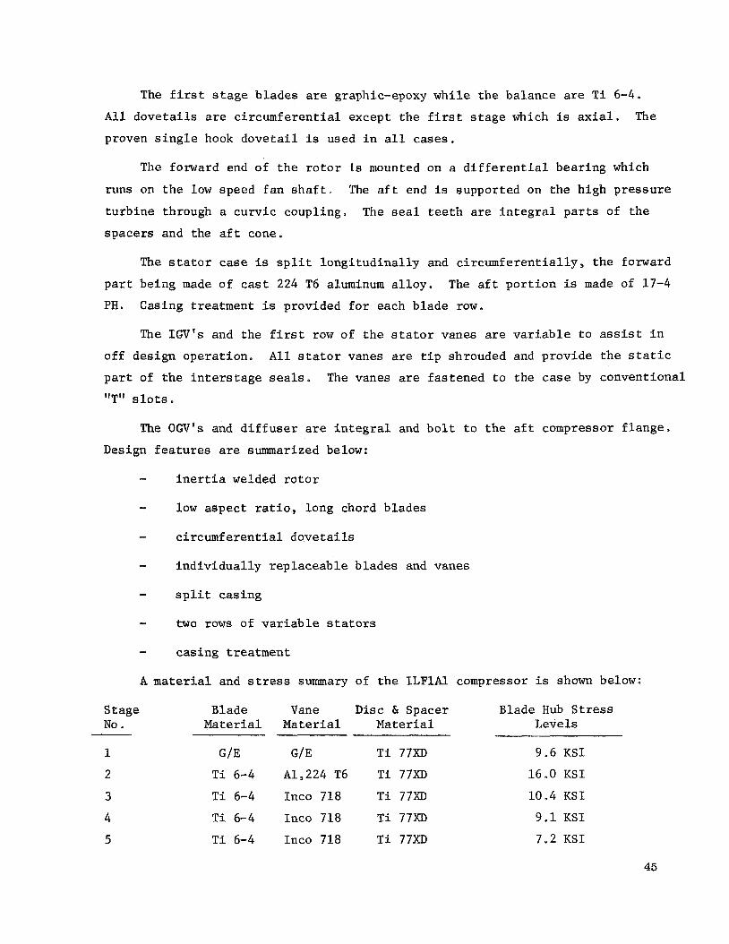
The f i r s t s t a g e b l ades are graphic-epoxy whi l e t h e ba lance are T i 6-4.
A l l d o v e t a i l s are c i r cumfe ren t i a l except t h e f i r s t s t a g e which i s axial . The
proven s i n g l e hook d o v e t a i l is used i n a l l cases.
The forward end of t h e r o t o r I s mounted on a d i f f e r e n t i a l bear ing which
runs on t h e low speed fan s h a f t . The a f t end is supported on t h e high p res su re
t u r b i n e through a cu rv ic coupling,,
spacers and the a f t cone.
The sea l t e e t h are i n t e g r a l p a r t s of t h e
The s t a t o r case is s p l i t l o n g i t u d i n a l l y and circumf e r e n t i a l l y , t h e forward
The a f t p o r t i o n is made of 17-4 p a r t being made of cast 224 T6 aluminum a l l o y .
PH. Casing t reatment is provided f o r each b lade row.
The I G V ' s and the f i r s t row of t h e s t a t o r vanes are v a r i a b l e t o assist i n
of f des ign opera t ion .
p a r t of t h e i n t e r s t a g e seals. "T" s l o t s e
A l l s t a t o r vanes are t i p shrouded and provide t h e s t a t i c
The vanes are f a s t ened t o the case by convent ional
The OGV's and d i f f u s e r are i n t e g r a l and b o l t t o t h e a f t compressor f l ange ,
Resign f e a t u r e s are summarized below:
- i n e r t i a welded r o t o r
- low aspec t r a t i o , long chord b lades
- c i r cumfe ren t i a l d o v e t a i l s
- i n d i v i d u a l l y r ep laceab le b lades and vanes
- s p l i t cas ing
- two rows of v a r i a b l e s t a t o r s
- cas ing treatment
A material and stress summary of t h e ILF lAl compressor i s shown below:
S tage Blade Vane D i s c 61 Spacer Blade Hub S t r e s s No Material Material Mat e r i a1 Levels
1 G/E G/E T i 77XD 9.6 KSI
2 T i 6-4 A1,224 T6 T i 77XD 16.0 KSI
3 T i 6-4 Inco 718 T i 77XD 10.4 KSI
4 T i 6-4 Inco 718 T i 77XD 9 . 1 K S I
5 T i 6-4 Inco 718 T i 77XD 7,2 K S I
45

Average metal temperatures are shown on Figure 74.
COMBUSTOR DESIGN
The reversed flow combustor arrangement was chosen s i n c e i t allowed a
s h o r t e r more compact engine.
flow of cool ing a i r through the HP nozzle thereby i n s u r i n g adequate cool ing
under a l l condi t ions of ope ra t ion .
This arrangement provides f o r a l a r g e , “30% c r o s s
Requirements
Q Minimum c o n t r i b u t i o n t o t h e engine l eng th
e 0.2 p a t t e r n f a c t o r
e Dual f u e l system
0 High space rate f o r minimum volume
0 No v i s i b l e smoke ( t o meet FAA emission requirements)
e Dual i g n i t i o n
e L i f e
P e r i n s t a l l a t i o n 1250 h r
To ta l 2500 h r
Combustor Aerodynamics Design
The combustion system f o r t h e engines is a h ighly loaded, reverse flow,
ca rbure t ing des ign . This conf igu ra t ion provides a very s h o r t , compact combus-
t i o n system t h a t is i d e a l l y matched t o t h e o v e r a l l con f igu ra t ion .
Airflow l eav ing the core engine compressor e n t e r s a s h o r t , s l i g h t l y curved
d i f f u s e r wi th an area r a t i o of 1 .4 which recovers about one h a l f of t h e compres-
s o r d i scharge v e l o c i t y head, This flow is then dumped i n t o an annular plenum
chamber which f eeds a i r i n the r e v e r s e d i r e c t i o n t o t h e dome and i n n e r l i n e r
s h e l l of t he combustor and t o t h e o u t e r s h e l l through t h e f i r s t s t a g e nozz le
vanes of t h e t u r b i n e . About 30% of t h e t o t a l flow passes r a d i a l l y through t h e
t u r b i n e vanes where i t is used t o convect ively cool t h e vanes and is then passed
through a small d i f f u s e r a t t h e t i p of each vane. These d i f f u s e r s reduce t h e
v e l o c i t y head down t o about one percent of t h e t o t a l p re s su re be fo re t h e flow
46

is dumped i n t o t h e o u t e r plenum region. An a d d i t i o n a l four pe rcen t of t h e t o t a l
f low e n t e r s t h e vanes a t t h e r o o t s e c t i o n and is used t o f i l m coo l t h e o u t e r
s u r f a c e s of t h e vanes.
Airflow moving forward a long t h e inne r and o u t e r combustor l i n e r w a l l s i s
The secondary d i l u t i o n used f o r l i n e r cool ing and f o r secondary d i l u t i o n a i r .
air i s used t o d i l u t e t h e h o t primary combustion gases down t o t h e r equ i r ed
t u r b i n e i n l e t temperature.
from t h e inne r annulus.
bus t ion zone of t h e burner .
About 42% of t h e t o t a l f low e n t e r s t h e dome r e g i o n
This f low i s used t o burn t h e f u e l i n t h e primary com-
For t h i s des ign about 10% of t h e t o t a l a i r f l o w is mixed w i t h t h e f u e l f low
i n annular pre-mixing chamber upstream of t h e dome. Addi t iona l comustion a i r
e n t e r s t h e dome through annular s l o t s l oca t ed on t h e inne r and ou te r s i d e s of
t h e pre-mixer. The s t r o n g cross-flow r e s u l t s i n i n t i m a t e mixing of t h e f u e l
and a i r i n t h e primary combustor r eg ion of t h e burner , which h e l p s t o achieve
good f lame s t a b i l i t y and e f f i c i e n t combustion.
A i r f o r t h e pre-mixer i s picked up by a set of 20 s e p a r a t e r a m scoops t h a t
are evenly spaced around t h e dome of t h e combustion system. Fuel is then
i n j e c t e d i n t o a l t e r n a t e a i r scoops from a set of 10 f u e l tubes t h a t p r o j e c t
i n t o t h e s i d e s of t h e scoops. I g n i t i o n of t h e f u e l - a i r mixture i s achieved
wi th e i t h e r of two electrical spa rk i g n i t o r s t h a t p r o j e c t through t h e upstream
end of t h e o u t e r combustor l i n e r from t h e o u t e r ca s ing of t h e c o r e engine.
Combustor gas f lowpaths are shown on Figures 75 and 76. Important design
f e a t u r e s are summarized below:
ILFlAl ILF2A1 & ILF2A2
6 Space Rate - (Btu/hr)/atm. f t . 12.5 x 1 0 12.5 x 10
Length/Height Ra t io 2 ,5 2.7
Temperature R i s e 1866" 1460"
No. of Nozzles 20 20
P a t t e r n Fac to r 0 .2 0.2
A P/P 0.07 0.07
47

OB
Reference Veloc i ty
ILFlAl ILF2A1 & ILF2A2
0 9875 0.9875
66 FPS 83FpS
Compressor Exit Mach No. 0.35 0.35
D i f f u s e r Dump Mach No. 0.25 0.25
Liner Material Hast X Hast X
Inne r S h e l l Material Inco 624 Inco 625
Outer S h e l l Material Inco 718 Inco 718
F i r e Safe ty
The b a s i c f i r e s a f e t y des ign is inhe ren t ly a low r i s k arrangement. The
remote c o n t r o l s and accesso r i e s are packaged i n a f i r e proof con ta ine r . The
double wal led f u e l manifold and nozz les are mounted i n s i d e of t h e f i r e proof
combustor o u t e r cas ing and t h e s t a t o r a c t u a t o r l i n e r s have double w a l l s .
One of t h e cons ide ra t ions i n convent ional t u r b i n e engines is t o make pro-
v i s i o n s f o r d r a i n i n g o u t unburned f u e l l e f t i n t h e engine from a f a l s e s ta r t .
This engine au tomat ica l ly d r a i n s through the t u r b i n e and out t h e exhaust nozz le
leav ing no dangerous pockets of f u e l .
The f u e l manifold shown (Figures 75 and 76) is a double wal led arrange-
ment l oca t ed i n s i d e of t he f i r e proof o u t e r combustion casing. The manifold can
b e a s i n g l e r i n g wi th one lead-in tube o r s p l i t i n t o 180' segments w i th two
lead- in tubes . This makes a s imple arrangement i n which t h e mid-space can be
s a f e l y vented overboard at the a f t end of t h e fan duc t . An a l t e r n a t i v e method
would be t o have an e x t e r n a l manifold which would not r e q u i r e double wa l l ing
b u t would r e q u i r e p i e r c i n g t h e combustor cas ing f o r every f u e l tube.
methods have t h e i r advantages; however, t he former seems t h e s imples t a t t h e
p re sen t t i m e
Both
The s t a t o r a c t u a t o r s are opera ted by f u e l l i n e p re s su re and are double
wal led i n t h e convent ional manner.
The non-engine mounted elements, a i r t u r b i n e , f u e l pump, lube and scavenge
48

pump, a l t e r n a t o r , c o n t r o l s , a i r coo le r and tank, are mounted i n t h e n a c e l l e i n
a s e p a r a t e f i r e proof enc losu res
Engine Emissions
It is recognized t h a t missi le smoke is not t h e only area which r e q u i r e s
treatment, A d e t a i l e d s tudy of methods t o reduce C 0 2 ' NOx, and t r a c e metals
emissions from the ILF engines has been sponsored by NASA and i s now underway.
The r e s u l t s of t h i s s tudy , and the changes i n combustor des ign r equ i r ed t o m e e t
va r ious levels of emissions w i l l be r epor t ed i n t h e NAS 14406 f i n a l r e p o r t , due
e a r l y i n 1972.
TURBINE DESIGN
The c o r e tu rb ines
des ign requirements:
Cycle
A h/T4
p41p5
w q p 4
N/
G J A h /2 U P2
wc/w2c% TI n e t
Ex i t Mach No.
designed i n t h i s program have the fol lowing aerodynamic
Core Turbine Design Requirements
ILFlAl ILF2A1 and ILF2A2
0.0526 0.0475
2 a 665 2.368
324 a 8 337.4
16 28 27 .71
0 .71 0.57
5 ,7 2.3
87.0 88.6
0.5 0 .5
-_I-
The tu rb ines are a l l s i n g l e s t a g e des igns w i t h t h e i r t i p diameters set re-
l a t ive t o t h e compressor diameter and an exi t area s i z e f o r 0.5 Mach N o .
Turbine performance w a s es t imated based on General E l e c t r i c Company's experi-
mental performance wi th similar tub ines .
t o determine the pre l iminary v e c t o r diagram,
d a t a is given i n Table XVIII.
Free vo r t ex c a l c u l a t i o n s were made
A summary of t he v e c t o r diagram
49

The tu rb ines are l i g h t l y loaded wi th f a i r l y h igh r e a c t i o n and nea r zero
l eav ing s w i r l . A b lad ing summary of t h e tu rb ines is shown below. Turbine
flowpaths are shown on Figures 77 and 78.
Core Turbine Blade Summarv
Cycle ILFlAl ILF2Al and ILF2A2
No. Nozzles 62 48
No. Blades 112 76
Rotor P i t c h l i n e Axial 1.05 a
Width ( i n . ) 1 . 2
Fan Drive Turbine Aerodynamic Design
The fan d r i v e tu rb ines have the fol lowing aerodynamic design requirements:
Fan Drive Turbine Design Requirements
Cycle ILFlAl ILF2A1 P
No. of Stages 3 3
ILF2A2
4
Ah/T54 0.0556 0 e 0468 0.0468
'T54/'T55 2.99 2.39 2.40
103 e 38
42.44
94 i 70
62.23
74.39
62.23
GJAh/2€UP2 2.54 2.04 2.23
rl 83.8 86.6 86.5
Exit Mach No. 0.42 0 e 415 0.416
The t u r b i n e flowpaths were designed t o be close-coupled wi th t h e co re
b i n e s ( i e e . 9 no t r a n s i t i o n passage between t u r b i n e s ) and have o v e r a l l aero-
dynamic work c o e f f i c i e n t s of 2 t o 2.5.
set f o r 0.4 Mach number. Turbine performance was es t imated based on an ex t r a -
p o l a t i o n of General Electr ic Company's experience.
c h a r a c t e r i s t i c s are summarized i n Table X I X .
The exi t areas behind t h e tu rb ines w e r e
Some of t h e t u r b i n e b lad ing
50

I n a l l cases, t h e energy w a s set on the las t s t a g e t o g i v e a prescr ibed
s w i r l level wi th t e n percent hub r e a c t i o n , The s w i r l level w a s s e l e c t e d based
on the o u t l e t guide vane design requirements , and the r e a c t i o n s level was s e l e c t e d
t o e l imina te d i f f u s i o n a c r o s s t h e r o t o r .
t i v e l y evenly among t h e i n i t i a l s t a g e s t o keep a l l t h e blade row leaving Mach
numbers about t h e same level.
were f r e e vo r t ex . A summary of t he vec tor diagram d a t a f o r a l l engines is
shown i n t a b l e s , XX, XXI and XXII.
The remaining energy was s p l i t rela-
A l l c a l c u l a t i o n s performed f o r t h e s e s t u d i e s
51

Data given i n NASA SP-36, "Aerodynamic Design of Axial Flow Compressors,"
w a s used t o determine t h e performance c h a r a c t e r i s t i c s of t h e o u t l e t gu ide vane
system, As shown i n F igure 79, t h e minimum expected p res su re l o s s corresponds
t o a D-factor of about 0.5.
assumed f o r compressor blade des ign , but t h e problem of compressor s t a l l does
not apply t o t h e s e o u t l e t gu ide vane des igns ,
and Mach number requirements occur a t t h e des ign p o i n t and tend t o be less a t
o the r opera t ing cond i t ions .
This va lue is higher than t h e D-factor u s u a l l y
That i s , t h e maximum tu rn ing
Ou t l e t Guide Vane
A summary of t h e o u t l e t guide vane des igns i s shown i n t h e fol lowlng t a b l e .
Ou t l e t Guide Vane Design Summary
Cycle TLFlAl ILF 2A1 ILF2A2
I n l e t Angle
Exit Angle
( O ) 38.8 36.7 31.6 P 0 0 (0) 0
NO * 128
. S o l i d i t y 1.8
14 0
1.75
86
1.14
D-Factor 0.51 0.49 0.475
P res su re Loss 0 024
AP /P
P i t c h l i n e Axial 0.95
Width ( i n . )
0.021 0.012
0.95 0.95
Turbine f lowpaths are shown on Figures 80, 81 and 82.
52
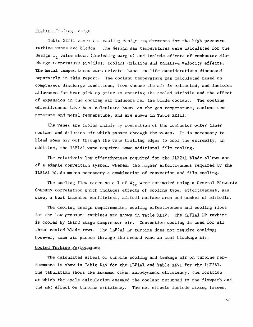
k? 12,- _i I-:” hi:$, 1, e 2 : f l j
Table X X I l h bku)ws coalin;; .:; . i .ikn 3-equiremenls f o r t h e high p res su re
tu rb ine vanes and b lades . The design gas temperatures were c a l c u l a t e d f o r t h e
design T4 va lue shown ( inc luding margin) and inc lude e f f e c t s of combustor d i s -
charge temperature p r o l i l z s , coolant d i l u t f o n and r e l a t i v e v e l o c i t y e f f e c t s .
The metal temperatures were s e l e c t e d based on l i f e cons ide ra t ions d iscussed
s e p a r a t e l y i n t h i s r e p o r t . The coolan t temperature w a s c a l c u l a t e d based on
compressor d ischarge cond i t ions , from whence t h e a i r i s e x t r a c t e d , and inc ludes
allowance f o r h e a t pick-up p r i o r to e n t e r i n g t h e cooled a i r f o i l s and t h e e f f e c t
of expansion i n t h e cool ing a i r inducers f o r t h e b l ade coolan t . The coo l ing
e f f e c t i v e n e s s have been c a l c u l a t e d based on t h e gas temperature, coo lan t tem-
p e r a t u r e and metal temperature , and are shown i n Table X X I I I ,
The vanes are cooled mainly by convect ion of t h e combustor o u t e r l i n e r
coolan t and d i l u t i o n ais which passes through t h e vanes. It is necessary t o
bleed some air O U ~ ttlimr~gh t h e vane t r a i l i n g edges t o coo l t h e ex t r emi typ i n
a d d i t i o n , t h e ILP1Al.vane r e q u i r e s some a d d i t i o n a l f i l m cool ing.
The r e l a t i v e l y low e f f e c t i v e n e s s r equ i r ed f o r t h e lLF241 b l a d e a l lows u s e
of a s imple convect ion system, whereas t h e h igher e f f e c t i v e n e s s r equ i r ed by t h e
ILFlAl b lade makes necessary a combination of convect ion and f i l m cool ing.
The coo l ing f low rates as a % of W2c w e r e es t imated us ing a General Electric
Company c o r r e l a t i o n which inc ludes e f f e c t s of coo l ing type, e f f e c t i v e n e s s , gas
side, a h e a t t r a n s f e r c o e f f i c i e n t , a i r f o i l s u r f a c e area and number of a i r f o i l s .
The coo l ing des ign requirements , cool ing e f f e c t i v e n e s s and cool ing f lows
f o r t he low p res su re t u r b i n e s are shown i n Table XXIV. The TLFlAl LP t u r b i n e
is cooled by t h i r d s t a g e compressor air .
t h r e e cooled b l ade rows.
however, some a i r passes through t h e second vane as seal blockage a i r ,
Convection cool ing i s used f o r a l l
The ILF2A1 LP t u r b i n e does not r e q u i r e cool ing;
Cooled Turbine Performance
The c a l c u l a t e d e f f e c t of t u r b i n e cool ing and leakage a i r on t u r b i n e per-
formance is show i n Table XXV f o r t h e ILFlAl and Table XXVI f o r t h e ILP2A1.
The t a b u l a t i o n shows t h e assumed c l e a n aerodynamic e f f i c i e n c y , t h e l o c a t i o n
a t which t h e c y c l e c a l c u l a t i o n assumed t h e coolan t r e tu rned t o t h e f lowpath and
t h e n e t e f f e c t on t u r b i n e e f f i c i e n c y . The n e t e f f e c t s i nc lude mixing l o s s e s ,
53

coolant pumping energy, and a v a i l a b l e expansion energy of t h e coo lan t from
ent rance t o t h e charging s t a t i o n .
High Pressure Turbine Mechnical Design
The c l o s e coupled reverse flow combustor r e s u l t s i n some depa r tu re s i n
h igh p res su re t u r b i n e des ign , p a r t i c u l a l y i n t h e s t a t o r area.
f e a t u r e s of t h i s t u r b i n e are:
B r i e f l y t h e
P a r t
Vanes
_I
Mat er i a l
MM509
Fea t u r e
Thru f low of “30% of core engine flow.
Blades N i 76XB Film cooled b lade
Wheel N i 75XD Thermally i s o l a t e d
Shroud R-120 Transp i r a t ion cooled
Impingement starter H a s t - X I n t e g r a l
Requirements
L i f e per i n s t a l l a t i o n 1250 h r . (20,000“) To ta l 2500 h r . (40 ,000 ’ )
Turbine I n l e t Temperature ILFlAl ILF2A1 ILF2A2
Max, Continous, F 2500 2000 2000 Max, Emergency, F 2585 2063 2063
4 115% emergency N f o r 5 minutes , normal continuous T
No goose neck between nozzle and r o t o r
S t a t o r
The HPT s t a t o r i nc ludes the fol lowing i t e m s :
Nozzle
Imp ingemen t st a r t er
Impingement starter manifold
Mid support cone
HPT t i p shroud
54

The HPT nozzle depa r t s from t h e usua l des ign p r a c t i c e i n t h a t it provides
cold a i r passages f o r about 30% of t h e combustion requirements. This l a r g e
quan t i ty of cool ing a i r p lus the 4% which i s bled out of t h e t r a i l i n g edges
of t h e vanes provides ample cool ing f o r t h i s member, Under max T cond i t ions 4 t h e metal temperature i s l imi ted t o less than 1950" F. The d ischarge s i d e of
t h e passages form d i f f u s e r s which drop t h e cool ing air v e l o c i t y a t that p o i n t
of 0.2 Mach number.
The impingement starter i s an i n t e g r a l p a r t of nozzle - midframe assembly.
The manifold and j e t nozzle extend 360' around t h e outer wall of t h e HPT flow
pa th providing t h e min imum bending moment t o t h e buckets during t h e s t a r t i n g
cycle .
The mid support core extends from the manifold t o the inne r su r face of t h e
f an duc t and inc ludes t h e tu rb ine shroud suppor t , This arrangement i n s u r e s
c l o s e alignment of the HPT s t a t o r and r o t o r p a r t s .
The HPT shroud is t r a n s p i r a t i o n cooled and located from t h e shroud support .
The s h o r t connection through the tu rb ine rear frame insu res good r o t o r t i p
c l ea rance con t ro l .
Rotor - The s i n g l e s t a g e HPT toge ther wi th the compressor mace up a two bear ing
r o t o r .
l i n g fas tened by a s i n g l e tubu la r b o l t which provides f o r minimum assembly and
disassembly time. The rear s tub s h a f t is f langed t o t h e a f t s i d e of the wheel
i n su r ing low stress i n t h e b o l t i n g area.
The connection between the compressor and t h e tu rb ine i s a curv ic coup-
The buckets are hollow wi th double hook case type d o v e t a i l s . They are
cooled by air t h a t e n t e r s through a s i n g l e passage i n t h e shank and d i scha rges
t h r u 0.005-inch diameter ho les .
The running elements of t h e seals are r ibbe ted t o t h e HPT wheel. Thus
t h e diameter of t h e seal t e e t h i s set by t h e wheel i t s e l f , i n su r ing a minimum
seal c l ea rance ex tens ion . The seal member themselves are so contained t h a t
even a f u l l l eng th axial c rack w i l l not cause ca t a s t roph ic f a i l u r e ,
55

The cool ing a i r f o r t h e buckets and t h e blockage a i r f o r t h e seals i s sup-
p l i e d from t h e compressor d ischarge through an inducer . This arrangement a l lows
minimum cool ing air temperature and the pa th e f f e c t i v e l y provides a wheel r i m
thermal b a r r i e r .
Key information on coo l ing , leakage, and materials is given below:
Cooling Flow (Percentages of W ) 2c
ILFlAl
Blade 3.1
Shroud 0.5
Nozzle 30
Leakage (Seals)
Nozzle-Rot o r
Rotor-LPT S t a t o r
Material
- Nozzle
Sea l s
Blade
Disc
Stub Sha f t
Metal Temperature
Nozzle F
Blade F
ILFlA1
2.25
0.8
ILF 2A1
1.1
0.2
30
ILF 2A1
1.7
0.7
ILF 2A2
1.1
0.2
30
ILF 2A2
1.7
0.7
Has te l loy X
MM509
N i 76XD
N i 75XD
I n 718
ILFlA1 ILF2A1 ILF2A2
1850 1 7 00 17 00
1610 1610 1600
A t y p i c a l d i s c stress curve is shown on Figure 83.
Low Pressure Turbine Mechanical Design
The low p res su re t u r b i n e s f o r t h e ILPlAl, ILF2A1, and ILF2A2 are similar
i n t h a t t h e i n t e g r a l disc-spacer cambination is overhung from a s i n g l e c o n i c a l
56

web.
suppor ts t he two heavy high p res su re r o t o r s . The ILFlAl and ILF2A1 have t h r e e
s t a g e tu rb ines and t h e ILF2A2 has a f o u r t h s t age .
The f a n , s h a f t and LPT comprise a s i n g l e two-bearing r o t o r which a l s o
Requirements
The requirements f o r t h e LPT are very similar t o those of t h e HPT. They
are:
120% d.esign N f o r 5 minutes
Continuous opera t ion a t max. r a t e d temperature'
L i f e
Per i n s t a l l a t i o n - 1250 h r
T o t a l - 2500
Q Cycles
Per i n s t a l l a t i o n - 20,000
T o t a l - 40,000
e I n l e t t o co inc ide wi th HPT e x i t
o Exi t diameter not t o exceed combustor OD
S t a t o r
The s t a t o r c o n s i s t s of t h r e e (four i n t h e case of t h e ILF2A2) vane rows
which hold toge the r t o form t h e s h e l l , t h e s t a t o r vane assembly and t h e i n t e r
s t a g e seals. This des ign has t h e advantage over convent ional arrangements i n
low weight and no d i s t o r t i o n due t o l o n g i t u d i n a l j o i n t s .
The ILFlAl r e q u i r e s 3.95% cool ing t o the 1st s t a g e nozzle and 1% t o t h e
2nd s t a g e nozzle.
The ILF2A1 r e q u i r e s e s s e n t i a l l y no cool ing. However, 1.3% blockage a i r is
requi red f o r t h e HP-LP seal and t h i s a i r is ducted through t h e 1st s t a g e nozzle .
The c a v i t y i s not r e a l l y cooled but i t i s purged wi th the leakage a i r from
t h e HP-LP seal and t h e N o . 3 and No, 4 bearing sump seals,.
The vanes and t h e i r ou te r and inne r bands and ex tens ions are considered
he re t o be i n t e g r a l c a s t i n g s . These could be made as a s i n g l e 360' u n i t o r as
57

segments later welded. The s t a t i c p a r t of t h e inne r seals are supported from
t h e inner shroud band. The seal su r face i t s e l f i s made up of small-cell honey-
comb
Rotor
The d i s c and spacers of t h e l a s t two s t a g e s ( l a s t t h r e e i n t h e ILF2A2) are
f a b r i c a t e d i n t o a s i n g l e u n i t . The spacers a l s o have t h e seal t e e t h as i n t e g r a l
p a r t s . The f i rs t s t a g e has a convent ional d i s c which is f langed t o t h e support
cone and t h e a f t r o t o r down.
The i n t e g r a l l y shrouded b lades are anchored by one hook axial d o v e t a i l .
The f i r s t s t a g e i n a l l t h r e e des igns uses a pos t type of anchorage al lowing f o r
b o l t i n s e r t i o n i n t h e r o o t area. The method of through b o l t i n g does not r e s u l t
i n t h e u s u a l stress concent ra t ion of a convent ional b o l t ho le .
The ILFlAl r e q u i r e s 1.25% cool ing a i r which passes through an inducer
mounted on t h e inner seal of t h e 1st s t a g e s t a t o r .
no t r e q u i r e coo l ing , as previous ly s t a t e d .
The ILF2A1 and ILF2A2 do
Sha f t and Coupling
The f a n s h a f t i s c o n i c a l i n shape t o provide t h e maximum r i g i d i t y between
t h e - f a n r o t o r and the LPT r o t o r s . The covering a l s o provides f o r t h e r a i s i n g
o f t h e o i l from t h e a f t sump t o t h e No. 1 and 2 bear ings i n t h e forward p a r t
of t h e engine.
The a f t end of t h e s h a f t is sp l ined i n t h e convent ional manner t o t h e LPT
s t u b s h a f t . Two l o c a t i n g l ands are provided, one on e i t h e r s i d e of the coupl ing
t e e t h .
Summary c h a r a c t e r i s t i c s of t he designs fol low:
Cooling Flows (percent WZc)
ILFlAl
Blade (1st) 1.25
Shroud (1s t ) 0.2 ( 2nd 1 0.1
Nozzle (1st) 3 * 9 5 (2nd 1 1.0
ILF2A1
None
0.2 0.1
None None
ILF2A2
None
0.2 0.1
None None
58
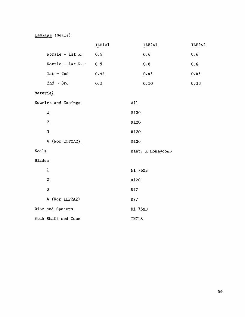
Leakage (Seals)
ILFlAl
Nozzle - 1st R. 0 .9
Nozzle - 1st R. ' 0.9
1st - 2nd 0.45
2nd - 3rd 0.3
Material
Nozzles and Casings
1
2
3
4 (For ILF2A2)
S e a l s
Blades
1
2
3
4 (For ILF2A2)
Disc and Spacers
Stub Shaf t and Cone
ILF2Al
0.6
0.6
0.45
0.30
A l l
R120
R120
R120
R120
H a s t X Honeycomb
N i 76XB
R120
R 7 7
R7 7
N i 75XD
IN718
ILF2A2
0.6
0.6
0.45
0.30
59
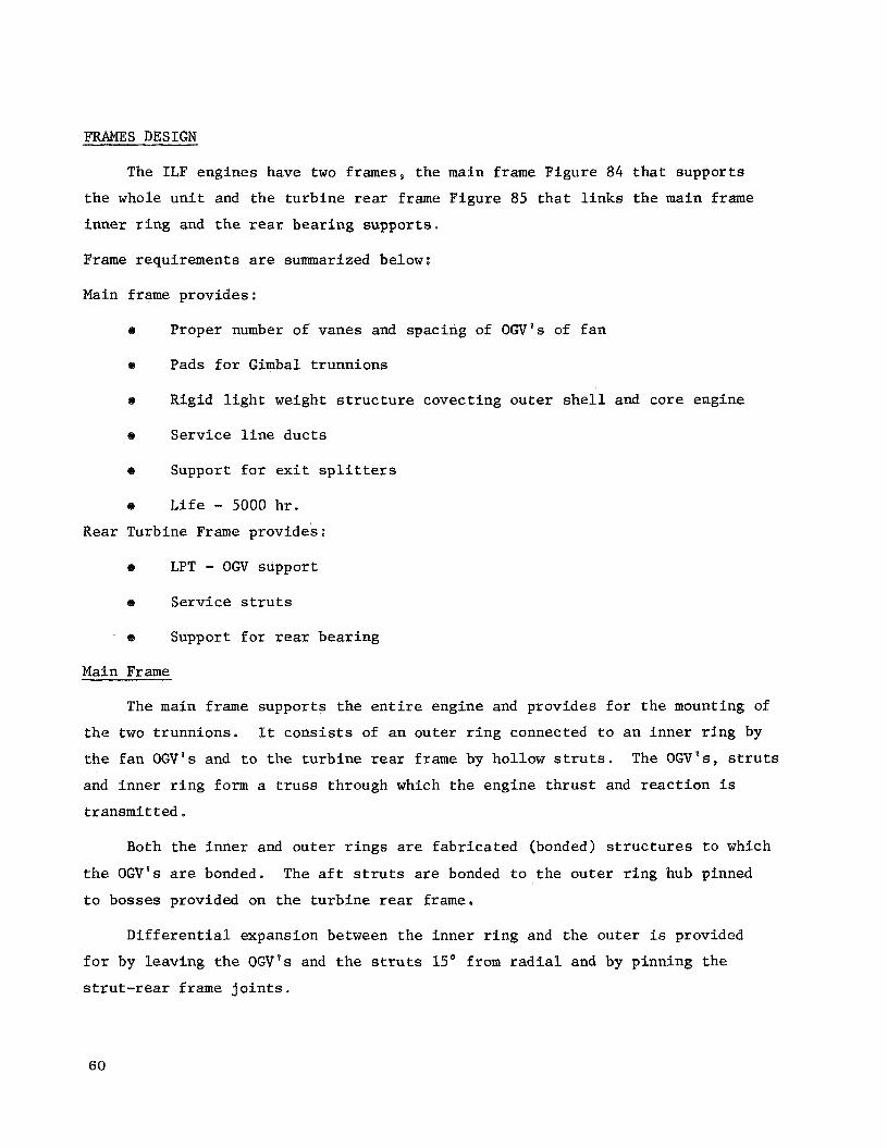
FRAMES DESIGN
The ILF engines have two frames, t he main frame Figure 84 t h a t suppor ts
t h e whole u n i t and the t u r b i n e rear frame Figure 85 t h a t l i n k s t h e main frame
inne r r i n g and t h e rear bea r ing suppor ts .
Frame requirements are summarized below:
Main frame provides:
Proper number of vanes and spacing of OGV's of f a n
Pads f o r Gimbal t runnions
Rigid l i g h t weight s t r u c t u r e covect ing ou te r s h e l l and core engine
Serv ice l i n e duc t s
B Support f o r exit s p l i t t e r s
e L i f e - 5000 h r .
Rear Turbine Frame provides:
ta LPT - OGV support
0 Service s t r u t s
- e Support f o r rear bear ing
Main Frame
The main frame suppor ts t h e e n t i r e engine and provides f o r t h e mounting of
t h e two t runnions .
t h e f a n O W ' S and t o t h e t u r b i n e rear frame by hollow s t r u t s .
and inne r r i n g form a t r u s s through which t h e engine t h r u s t and r e a c t i o n i s
t ransmi t ted a
It c o n s i s t s of a n ou te r r i n g connected t o a n inne r r i n g by
The OGV's, s t r u t s
Both t h e i n n e r and o u t e r r i n g s are f a b r i c a t e d (bonded) s t r u c t u r e s t o which
t h e OGV's are bonded.
t o bosses provided on t h e t u r b i n e rear frame,
The a f t s t r u t s are bonded t o t h e ou te r r i n g hub pinned
D i f f e r e n t i a l expansion between t h e inne r r i n g and t h e ou te r i s provided
f o r by leaving t h e OGV's and t h e s t r u t s 15' from r a d i a l and by pinning t h e
s t r u t - r e a r frame j o i n t s .
60

Two t runnion bases o r pads are a n i n t e g r a l p a r t of t h e o u t e r r i ng . The
prime f u n c t i o n of t h e s e pads i s t o spread t h e load from t h e mount t o t h e ou te r
r ing .
cas t ing .
mount t o a l low f o r d i f f e r e n t i a l expansion.
The des ign i s shown i n F igure 86 and may b e e i t h e r a f a b r i c a t i o n o r a One t runnion w i l l b e b a l l mounted and t h e o t h e r w i l l have a r o l l e r
The p r i n c i p a l load on t h a t p a r t w i l l be from t h e engine t h r u s t , as "G"
and "gyro" are small.
Rear Frame
The t u r b i n e rear frame u t i l i z e s bo th OGV's and s t r u t s t o connect t h e o u t e r
r i n g t o t h e inner . The s i x l a r g e s t r u t s provide f o r hub passages and anchorage
suppor ts as seen i n F igures 85. The main s t r u t s are a l s o bossed t o accommodate
t h e two exhaust nozz le suppressor r i n g s .
Main f e a t u r e s of t h e frame des ign are:
Main Frame
OGV - Sol id Al 6061
Turbine Rear Frame
S i x S t r u t s
6 rear s t r u t s hollow 321SS Lube and scavenge l i n e s duct.ed through s t r u t s
o Pinned c o r e j o i n t s INCO 625 material
8 Trunnion pads on o u t e r r i n g OGV No. ILFJAl/ILF2A2/ILF2A2 140/128/86
61

DUCT AND NOZZLE AERODYNAMIC DESIGN
Fan Duct
Because of t h e low f a n p res su re r a t i o s involved i n t h e des igns , t h e f a n
duc t from t h e OGV t o t h e e x i t i s almost cons tan t area, except f o r contour ing
r equ i r ed t o account f o r t h e blockage of t h e a c o u s t i c s p l i t t e r s and rear f a n
frame. F r i c t i o n l o s s e s i n t h e f a n duc t are ca l cu la t ed i n t h e s tandard manner
wi th t h e f r i c t i o n c o e f f i c i e n t increased t o account f o r t h e e f f e c t of t h e sur -
f a c e ho le s i n t h e a c o u s t i c t rea tment material.
drag l o s s e s from t h e s t r u t s , s p l i t t e r s and t h e i r i n t e r s e c t i o n s are es t imated
based on Horner 's "Aerodynamic Drag" as w e l l as exper ience gained from evalua-
t i o n of e x i s t i n g similar systems. Duct v e l o c i t y and f low c o e f f i c i e n t s are
based on recent l a r g e scale test experience.
P res su re drag and i n t e r f e r e n c e
A t a n ope ra t ing cond i t ion where t h e r e fe rence duc t Mach number is 0.5,
l o s s e s are as fol lows:
F r i c t i o n 0 e 0097
P res su re drag of s t r u t s and 0.0040 s p l i t t e r s
I n t e r f e r e n c e drag of s t r u t s and 0.0013 s p l i t t e r s
T o t a l 0.015
I n a c t u a l p r a c t i c e , s i n c e t h e loss i s a f u n c t i o n of duc t Mach number, t h e
computer deck r e p r e s e n t a t i o n i s g iven as:
The va lue of K is c a l c u l a t e d t o match t h e loss a t t h e des ign p o i n t chosen.
The duct v e l o c i t y c o e f f i c i e n t , Cv28 and duc t f low c o e f f i c i e n t CF2* have
been e s t a b l i s h e d a t 0.995 and 0.975, r e spec t ive ly .
Core Duct
A s i n t h e case of t h e f a n duc t , t h e c o r e duc t is e s s e n t i a l l y a cons t an t
area passage from t h e t u r b i n e e x i t gu ide vanes t o t h e e x i t of t h e nozz le .
low Mach number ( - 0 . 4 ) r e s u l t s from t h e r e l a t i v e l y h igh e x t r a c t i o n from t h e core ,
This
62
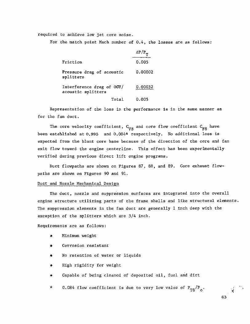
requi red
For
t o achieve low j e t co re no i se .
t h e match po in t Mach number of 0.4, t h e l o s s e s are a s fol lows:
F r i c t i o n
P res su re drag of a c o u s t i c 0 e 00002 s p l i t t e r s
I n t e r f e r e n c e drag of OGV/ a c o u s t i c s p l i t t e r s
0 00032
Tota l 0.005
Representa t ion of t h e l o s s i n t h e performance i s i n the same manner as
f o r t he f an duc t .
The core v e l o c i t y c o e f f i c i e n t , Cv8 and core f low c o e f f i c i e n t CF8 have
been e s t ab l i shed a t 0.995 and 0.084* r e s p e c t i v e l y , No a d d i t i o n a l l o s s is
expected from t h e b lun t core base because of t h e d i r e c t i o n of t h e core and f a n
exit flow toward t h e . e n g i n e c e n t e r l i n e . Th i s e f f e c t has been exper imenta l ly
v e r i f i e d dur ing previous d i r e c t l i f t engine programs,
Duct flowpaths are shown on Figures 87, 88, and 89, Core exhaust flow-
pa ths are shown on Figures 90 and 91.
Duct and Nozzle Mechanical Design
The d u c t , nozzle and suppress ion su r faces are in t eg ra t ed i n t o t h e o v e r a l l
engine s t r u c t u r e u t i l i z i n g p a r t s of t h e frame s h e l l s and l i k e s t r u c t u r a l elements.
The suppress ion elements i n t h e f a n duc t are gene ra l ly 1 inch deep wi th t h e
except ion of t h e s p l i t t e r s which are 3 / 4 inch.
Requirements are as fo l lows:
Minimum weight
Corrosion r e s i s t a n t
No r e t e n t i o n of water or l i q u i d s
High r i g i d i t y f o r weight
Capable of being cleaned of depos i ted o i l , f u e l and d i r t
I I * 0.084 flow c o e f f i c i e n t i s due t o very low va lue of P /P I L T 8 o * , ;d
63
I n t h e case of t h e c o r e engine d ischarge - high temperature
L i f e - 5000 h r .
80,000 c y c l e s
Low c o s t
R e s i s t a n t t o d e t e r i o r a t i o n under b u f f e t i n g and high sound i n t e n s i t y
The ou te r duc t must provide sound suppress ion material f o r i t s f u l l l e n g t h ,
support t h e f a c e t i p sea l , and form t h e ou te r su r f ace f o r t h e f a n nozzle . The
aluminum honeycomb s t r u c t u r e s e l e c t e d meets t h i s c r i te r ia as w e l l as t h e gene ra l
requirements l i s t e d p rev ious ly ,
cel ls , 1 inch deep wi th 0.020 inch ou te r and inner walls.
The panel material w a s made up of 1 / 4 inch
The cel ls were vented t o ad jacen t c e l l s such t h a t water would d r a i n from
one t o t h e next and a t t h e same t i m e provide a mult iphase type of suppressor .
The cell w a l l s , which are 0.0025 inch t h i c k w i l l be pro tec ted from corro-
s i o n by a non-metall ic coa t ing .
The inner w a l l of t h e f a n duc t t akes advantage of t h e s u b s t a n t i a l frame
and support members as one w a l l of t h e suppressor member, t hus e x t e r n a l load-
i n g i s no problem.
The suppressors o r nozzle f o r t h e gas genera tor are made cf IN718 t o s tand
t h e exhaust gas temperature .
low temperature ou te r duc t . F igures 92 i d e n t i f i e s t h e material and l o c a t i o n
of t h e pane ls .
The b a s i c cons t ruc t ion i s similar t o t h a t of t h e
64
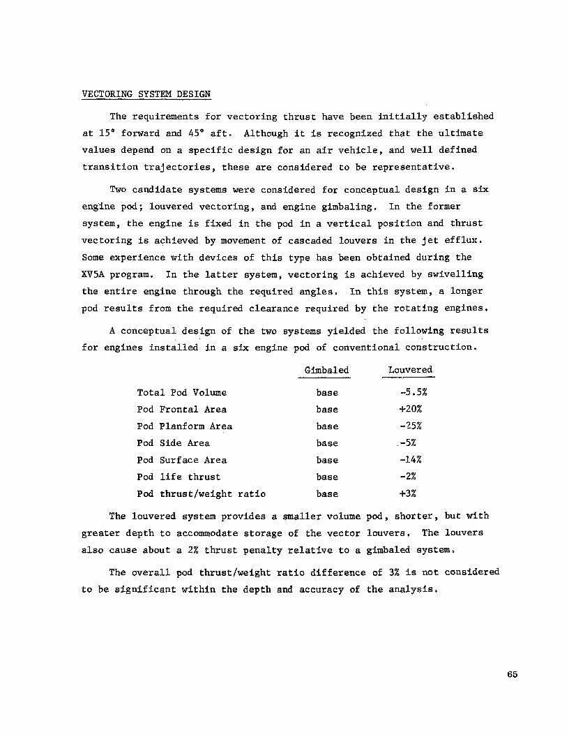
VECTORING SYSTEM DESIGN
The requirements f o r vec to r ing t h r u s t have been i n i t i a l l y e s t ab l i shed
a t 15' forward and 45' a f t . Although i t is recognized t h a t t h e u l t i m a t e
va lues depend on a s p e c i f i c des ign f o r an a i r v e h i c l e , and w e l l def ined
t r a n s i t i o n t r a j e c t o r i e s , t h e s e are considered t o be r e p r e s e n t a t i v e .
Two candida te systems were considered f o r conceptual des ign i n a six engine pod; louvered vec to r ing , and engine gimbaling. In t h e former
system, t h e engine i s f ixed i n t h e pod i n a v e r t i c a l p o s i t i o n and t h r u s t
vec to r ing i s achieved by movement of cascaded louvers i n t h e j e t e f f l u x .
Some experience wi th devices of t h i s type has been obtained dur ing t h e
XV5A program.
t h e e n t i r e engine through t h e requi red a n g l e s ,
pod r e s u l t s from t h e requi red c l ea rance requi red by the r o t a t i n g engines ,
In t h e lat ter system, vec to r ing is achieved by swive l l i ng
In t h i s system, a longer
A conceptual des ign of t h e two systems y ie lded the fo l lowing r e s u l t s
f o r engines i n s t a l l e d i n a six engine pod of convent ional cons t ruc t ion .
Gimbaled Louvered
T o t a l Pod Volume
Pod F r o n t a l Area
Pod Planform Area
Pod Side Area
Pod Surface Area
Pod l i f e t h r u s t
base -5.5%
base c20%
bas e -25%
base -5%
bas e -14%
base -2%
Pod thrus t /weight r a t i o base +3%
The louvered system provides a smaller volume pod, s h o r t e r , but wi th
g r e a t e r depth t o accommodate s t o r a g e of t he v e c t o r l ouve r s , The louvers
a l s o cause about a 2% t h r u s t pena l ty relative t o a gimbaled system.
The o v e r a l l pod thrus t /weight r a t i o d i f f e r e n c e of 3% i s n o t considered
t o be s i g n i f i c a n t w i t h i n t h e depth and accuracy of t h e a n a l y s i s .
65

Some q u a l i t a t i v e f a c t o r s a f f e c t i n g the s e l e c t i o n of a system are:
G imb a1 ed Louvered
Simpl ic i ty g r e a t e r less
Number of p a r t s fewer g r e a t e r
Crossflow c h a r a c t e r i s t i c s b e t t e r worse
Actuat ion f o r c e s lower h igher
A i r s t a r t i n g easier more d i f f i c u l t
Based on t h e s e two comparisonsp a gimbaled vec to r ing system w a s s e l e c t e d
f o r prel iminary des ign use. A s p rev ious ly s t a t e d , r e l a t i v e t o t h e des ign
t h r u s t vec to r range requirements , i t is recognized t h a t s e l e c t i o n of a
vec to r ing system is very c l o s e l y connected t o t h e a i r v e h i c l e conf igura t ion ,
and t h e u l t i m a t e des ign may evolve t o gimbaled, louvered, c lamshel l , or some
o t h e r design n o t p r e s e n t l y i n hand. The p o i n t i s t h a t t h e engine can b e
designed t o be compatible wi th any i n s t a l l a t i o n conf igu ra t ion , recognizing
t h a t some may r e q u i r e more work and complexity than o t h e r s .
Figure 93 and 94 i l l u s t r a t e t h e concept of t h e gimbaled vec to r ing system.
The engines are mounted between two beams on bear ing suppor ts and are d r iven
by hydraul ic a c t u a t o r s mounted on t h e beams.
each o t h e r by synchronizing rods t i e d t o t h e end of t h e a c t u a t o r arms s o that
a l l engines have t h e same v e c t o r angle .
of redundancy i n t h e event of a c t u a t o r f a i l u r e .
and mounting system i s shown on Figure 95 . One bear ing i s a r o l l e r t ype and the
o the r of t h e b a l l type t o a l low f o r d i ame t ra l growth. The support system i s
arranged f o r r a p i d l y dismounting t h e engine from i t s suppor ts .
Engines are connected t o
This system a l s o provides a degree
A c r o s s - s e c t i o l ~ of t h e bear ing
BEARINGS, SEALS, AND LUBE SYSTEM DESIGN
Lubr ica t ion System
The l u b r i c a t i o n system of t h e I n t e g r a l L i f t Fan con ta ins t h e fol lowing
sub-systems:
66

O i l Supply Sub-system
O i l Scavenge Sub-system
O i l Sea l P r e s s u r i z a t i o n Sub-system
Sump Vent Sub-system
A dry sump i s used, as i n a l l o the r General E l e c t r f c j e t engines . O i l
i s p r e s s u r e fed t o each engine component which r e q u i r e s l u b r i c a t i o n and/or
cool ing and is removed from t h e sump areas by scavenge pumps.
of t h e system o i l supply i s thereby r e t a i n e d i n t h e o i l tank.
system schematic diagram i s shown i n F igure 96.
The bulk
The l u b r i c a t i o n
O i l Supply Sub-System
The o i l supply sub-system c o n s i s t s of the o i l t ank , which se rves as t h e
main r e s e v o i r of o i l i n t he system, the o i l supply pump, o i l supply f i l t e r ,
and o i l supply nozz les . O i l i s suppl ied t o the i n l e t of t h e supply pump from
t h e o i l tank.
and d i s t r i b u t e d t o t h e engine by t h e o i l supply nozz les .
O i l under p re s su re is then routed through t h e supply f i l t e r
O i l supply p re s su re t o t h e engine s h a l l be l imi t ed dur ing cold starts
i n order t o avoid d r a i n i n g excess power from t h e accessory d r i v e system.
s t a t i c l e a k check valve prevents leakage from t h e o i l tank i n t o t h e engine
during per iods of engine shutdown.
downstream of t h e s t a t i c leak check va lve . The p res su re t a p i n d i c a t e s o i l
p re s su re ac ross t h e o i l supply nozz les hence w i l l be s e n s i t i v e t o o i l
temperature and flow rate. Abrupt changes i n o i l supply p re s su re w i l l be
i n d i c a t i v e of broken nozz les , plugged nozz le s , l o s s of o i l or o the r system
malfunct ions. The o i l supply pump is pro tec ted from contamination by an i n l e t
s c reen
A
An o i l supply p re s su re t a p is loca ted
O i l Scavenge Sub-systems
The o i l scavenge sub-system c o n s i s t s of t h e scavenge pumps, and o i l
cooler and scavenge o i l d e r a t o r .
67

Each major area of t h e engine i s scavenged by a s e p a r a t e pumping
element. The combined flow is then routed through t h e o i l coo le r and back
t o t h e o i l tank v i a t h e scavenge o i l de ra to r which r econd i t ions t h e o i l f o r
re-use by t h e engine.
Each pumping element is pro tec ted from contaminat ion, p a r t i c l e s too
l a r g e t o pass through t h e element without causing damage, by a n i n l e t
sc reen . Each scavenge i n l e t s c reen conta ins a magnetic ch ip d e t e c t o r t o
c o l l e c t f e r r o u s p a r t i c l e s which may i n d i c a t e f a i l u r e of a main s h a f t bear ing.
Sea l P r e s s u r i z a t i o n A i r Sub-system
Main s h a f t o i l seals r e q u i r e p r e s s u r i z a t i o n a i r i n order t o cause a i r
t o flow a c r o s s t h e seals i n t o t h e sumps a t a l l ope ra t ing condi t ions .
a i r i s allowed t o flow ou t of t h e sump through an o i l seal, some o i l is c a r r i e d
wi th i t . This o i l leakage must be e l imina ted i n order t o prevent excess o i l
consumption and seal coking. P r e s s u r i z a t i o n a i r i s ex t r ac t ed from t h e compressor
and routed t o t h e va r ious engine o i l seals,
I f
Vent Sub-system
Each area of t he engine, which r e q u i r e s p r e s s u r i z a t i o n of o i l seals, i s
This vented t o remove the a i r which e n t e r s t h e sumps through t h e o i l seals.
a l s o a l lows t h e sump i n t e r n a l p re s su re t o remain low enough t o prevent r e v e r s e
a i r flow out through t h e o i l seals dur ing a r ap id power reduct ion . The engine
i s vented r a d i a l l y inward through t h e low p res su re s h a f t and routed forward
and out t o t h e f a n d ischarge cav i ty .
Lube System Components
A d e s c r i p t i o n of t he major lube system components is as fol lows:
O i l Tank
The o i l t ank func t ions t o :
S to re engine l u b r i c a t i n g o i l
Supply o i l t o t h e engine over t he range of a l t i t u d e requirements ,
68
Provide f o r removal of a i r from t h e scavenge a i r / o i l mixture .
Provide space t o accommodate system f l u i d volume changes.
The scavenge system of the engine w i l l r e s u l t i n a dera ted scavenge
o i l flow being re turned t o the tank.
a s ta t ic c e n t r i f u g a l d e r a t o r .
scavenge r e t u r n chamber i n a t a n g e n t i a l d i r e c t i o n a t r e l a t i v e l y low v e l o c i t y .
The mixture then passes through t h e vo r t ex genera tor which accelerates t h e
mixture and d i scha rges i t i n a s w i r l i n g motion of t h e w a l l s of t h e vo r t ex
tube.
l i g h t e r a i r forms a v o r t e x i n t h e c e n t e r of t h e tube.
of t h e top of t h e assembly and o i l i s discharged i n t o t h e o i l t ank and i s
ready f o r reuse.
A i r removal w i l l be accomplished by
The scavenge a i r / o J l mixture e n t e r s t h e
Cen t r i fuga l f o r c e holds t h e o i l on t h e w a l l s of t h e tube and t h e
A i r is vented out
The o i l tank s i z e of 1.8 g a l l o n s i s determined by adding t h e fol lowing
volumes :
Unusable O i l
Th i s is t h e q u a n t i t y of o i l requi red t o provide f l u i d wi th air en t r a in -
Th i s volume i s a func t ion of system ment of less than 10 pe rcen t by volume.
mechanization d e r a f o r conf igu ra t ion , f low rates through t h e t ank , a r t i t u d e
requirements and t ank shape. This volume s h a l l be approxtmately 0.25 ga l lon ,
Usable O i l
Usable o i l shall be approximately 1.25 g a l l o n s and i s determined by adding ~
t h e fo l lowing allowances:
Mission o i l c a p a c i t y - That volume allowed f o r engine consumption
I
1
dur ing t h e requi red mission. Mission capac i ty of 1.0 ga l lon i s provided.
Gulping volume - Previous experience has shown a d i f f e r e n c e between
non-operating f u l l level and f u l l level when t h e engine i s a t m a x power.
This d i f f e r e n c e i s def ined as gulp ing volume.
provided i n t h e tank.
An allowance of 0.25 g a i l o n is
69

Expansion Volume
Expansion volume s h a l l be 20% of t h e usab le and unusable volume, This
volume al lows f o r foam and thermal expansion of t h e o i l , and provides space
t o keep t h e tank ven t clear over the range of engine a t t i t u d e s .
Lube and Scavenge Pump
The lube and scavenge pump is d r iven by t h e accessory d r i v e system and
c o n s i s t s of one p o s i t i v e displacement lu3e system element and two p o s i t i v e
displacement scavenge elements. Each element is pro tec ted wi th a removable
non-bypassing i n l e t screen. The i n s t a l l e d i n l e t s c reens w i l l prevent en t rance
of any p a r t i c l e g r e a t e r than 0,037-inch x 0.037-inch have have an e f f e c t i v e
flow area of 4 t i m e t h e c r o s s s e c t i o n a l area of the element i n l e t p o r t . The
scavenge element i n l e t s c reens s h a l l a l s o inc lude magnetic ch ip c o l l e c t o r s ,
A cold start bypass check va lve s h a l l be provided to l i m i t o i l supply p re s su re
dur ing cold starts,
f i l t e r and s h a l l r e l i e v e t o t h e i n l e t of a scavenge pump,
The va lve s h a l l be loca ted downstream of t h e lube supply
Lube and scavenge pump s i z e s s h a l l be as fol lows:
O i l Flow I n l e t P res su re
a. Lube supply 6.0 gpm 12 - 14 p s i g
b. Forward scavenge 6.0 gpm 12 - 14 ps ig
c. Af t scavenge 6.0 gpm 12 - 14 ps ig
Lube Supply F i l t e r
The lube supply f i l t e r s e r v e s t o p r o t e c t t h e lube supply nozz les from
containment as w e l l as remove system generated contamination such t h a t
system c l e a n l i n e s s i s maintained a t an acceptab le level. The f i l t e r s h a l l
be a non-bypassing f u l l f low type wi th a f i l t r a t i o n level of 46 microns
nominal. An automatic service s h u t off provis ion s h a l l be incorpora ted i n t o
t h e u n i t t o prevent system dra inage while t h e f i l t e r i s being se rv iced , The
p res su re d i f f e r e n t i a l a c r o s s t h e f i l t e r s h a l l not exceed 10 p s i f o r a new
o r newly cleaned f i l t e r wi th f u l l f low, 6 - -I. 0,25 gpm, of o i l a t 80 t o 100" F.
70

Sta t i c Leak Check Valve
A s t a t i c l eak check valve s h a l l b e provided t o prevent leakage from t h e o i l t ank
i n t o t h e engine during pe r iods of engine shutdown.
a minimum cracking p res su re of 5 p s i .
f u l l o i l flow of 6 gmp wi th a pressure drop no t exceeding 10 p s i a t 80 t o 100" F.
The check valve s h a l l have
The valve s h a l l b e capable of pass ing
O i l Cooler
The o i l cooler s h a l l be capable of t r a n s f e r r i n g t h e engine l u b e system
h e a t r e j e c t i o n t o t h e engine f u e l . The o i l s l i d e of t h e coo le r s h a l l b e
capable of wi ths tanding a t r a n s i e n t p re s su re of 1,000 p s i .
o r v i s c o s i t y s e n s i t i v e c o n t r o l valve s h a l l b e provided which w i l l bypass
o i l back t o t h e o i l t ank during cold s t a r t i n g and hence a i d engine o i l
warmup. The coo le r s h a l l be capable of h e a t r e j e c t i o n as fol lows:
A temperature
O i l i n Flow Temp. Fuel i n Flow Temp. Heat Rejec t ion ppm O F ppm O F Btu/min
45 240 80 200 1,850
O i l Supply Temperature Tap
An o i l supply preasure t a p s h a l l b e provided t o i n d i c a t e p re s su re
d i f f e r e n t i a l ac ross t h e lube nozz les .
p s i wi th an o i l flow of 6 gpm a t 150' F.
The o i l p re s su re s h a l l b e 45 5 10
Main Sha f t Bearinps
Considerable a t t e n t i o n has been p a i d t o t h e design of t h e main s h a f t
bea r ings . Detail c a l c u l a t i o n s , u t i l i z i n g t h e RECAP computer a n a l y s i s method
and o t h e r a n a l y t i c a l techniques have been made t o determine f a t i g u e l i f e
and proper l u b r i c a t i o n .
The f a t i g u e l i f e of t h e bea r ing w a s determined from a d e t a i l e d load
a n a l y s i s t ak ing i n t o account t h e bea r ing capac i ty and t h e d e t a i l e d geometry
of the bea r ing .
program and t h e l i f e w a s determined. The r e s u l t s w e r e modified by a f a c t o r
of 5 f o r M50 material,
Th i s in format ion w a s appl ied t o an advanced d i g i t a l computer
The fo l lowing t a b l e shows t h e bea r ing l i f e f o r t h e I n t e g r a l L i f t Fan
engines
71

P o s i t i o n Materia 1 Bore DN Capacity L i f e l b e Hours - mm
L. P. Thrust Ausf ormed 545 2,6 16,180 15,416
H, P. Thrust Ausf ormed 165* 1.98 11,362 15,930
I n t e r s ha f t M 5 0 60 0.75 5,353 23,775
L. P, Rol l e r M 5 0 60 0.25 5,353 87,800
M50
M50
* Counter r o t a t i n g .
Cr i t ica l Speeds
The r o t o r assemblies of t h e s e engines are close-coupled-r igidly mounted
des igns . The l i n k between t h e N o . 1 bearing and t h e N o . 4 bear ings i s f u r t h e r
s t i f f e n e d by t h e t r u s s type main frame.
c r i t i ca l s w e l l above 120% max. des ign speeds,
Pre l iminary estimates i n d i c a t e
Sea l s
Labyrinth seals are used throughout t h e I n t e g r a l L i f e Fan engines .
Labyrinth seals were s e l e c t e d because of t h e l a r g e diameter and high s u r f a c e
speed of t h e seal ad jacent t o t h e t h r u s t bear ings .
been used ex tens ive ly and s u c c e s s f u l l y on t h e 547, TF39 and CE6 engines . The
low f l i g h t speed and a l t i t u d e where the I n t e g r a l L i f t Fan engines w i l l be used
assumes coo l a i r f o r seal p r e s s u r i z a t i o n without t h e hazard of o i l coking.
Labyrinth seals have provided dependable wear f r e e systems when used wi th
adequately vented sumps.
Th i s type of seal has
CONTROLS AND ACCESSORIES D E S I G N
In t roduc t ion
The c o n t r o l system s e l e c t e d f o r t h e I n t e g r a l L i f t Fan u t i l i z e s t h e most
advanced components and l o g i c p re sen t ly a v a i l a b l e c o n s i s t e n t w i th engine
requirements , An air t u r b i n e d r iven f u e l pump w a s s e l e c t e d as t h e f u e l supply
t o e l imfnate t h e need f o r a r a d i a l d r i v e s h a f t and gearbox; and a l l r equ i r ed
72

computation i s done e l e c t r o n i c a l l y wi th f u e l a t pump d ischarge p res su re
providing t h e hydraul ic power.
M a j o r Assumptions
Fuel pump s ized f o r 4500 pph normal s teady s ta te flow a t dP
of 450 p s i d , Addi t iona l flow requirements ( s t a t o r , pump servo ,
cold day and t r a n s i e n t t h r u s t , and accel flows) br ing t h i s t o t a l
t o 7500 pph,
O i l hea t exhanger r equ i r ed .
I g n i t i o n power and l o g i c suppl ied by the c r u i s e engine.
A i r impingement s t a r t i n g .
A l l a i r and f u e l p ip ing assumed t o be AMs 321 f o r purposes of
weight estimates.
E l e c t r o n i c computer and cab le s loca ted i n an environment which
never exceeds 200' F.
A i r t u r b i n e suppl ied by c r u i s e engine o r APM during s ta r t and a c c e l
t o i d l e ,
System Desc r ip t ion
A s can be seen from t h e schematic i n Figure 9 7 , t h e c n n t r o l system
c o n s i s t s of an a i r t u r b i n e d r iven f u e l pump and a l t e r n a t o r , an e l e c t r o n i c
computer, v a r i o u s a i r and f u e l v a l v e s , and engine sensors .
The a i r t u r b i n e i s d r iven by c r u i s e engine CDP o r APM a i r dur ing l i f t
engine s t a r t i n g and a c c e l e r a t i o n t o i d l e ; a t i d l e , t h e shutof f va lve i s
closed and l i f t engine CDP a i r i s used. Check valves are l o c a t e d , as shown
i n each supply l i n e t o prevent r eve r se f low from c r u i s e engine CDP t o l i f t
engine CDP o r vice versa.
The q u a n t i t y of a i r suppl ied t o t h e a i r t u r b i n e i s con t ro l l ed by a n a i r
valve which i s pos i t ioned by a f u e l d r iven a c t u a t o r . The f u e l a c t u a t o r i s
73

pos i t ioned by a torque motor se rvo valve which p o r t s pump d ischarge p res su re
t o the appropr i a t e s i d e of the a c t u a t o r p i s t o n .
t h i s manner a l lows f u e l pump speed t o be c o n t r o l l e d .
Con t ro l l i ng t h e a i r f l o w i n
The f u e l pump is a p o s i t i v e displacement vane pump. Therefore , by
c o n t r o l l i n g pump speed, f u e l f low is a c t u a l l y being c o n t r o l l e d .
v a l v e is loca ted a t t h e pump d ischarge t o minimize f u e l p re s su re v a r i a t i o n so
t h a t t h e torque motor se rvo valves ope ra t e wi th small pres su re ga in changes,
A p r e s s u r i z i n g
A second solenoid valve is mounted on t h e pump package t o p o s i t i o n t h e
l i f t engine v a r i a b l e s t a t o r s . This va lve o p e r a t e s as does t h e prev ious one,
f l u i d is ported t o t h e head s i d e or rod s i d e of t he s t a t o r a c t u a t o r s depending
upon t h e d i r e c t i o n of des i r ed s t a t o r motion.
The a l t e r n a t o r , which i s loca ted on t h e oppos i te s i d e of t h e a i r t u r b i n e
from t h e pump, provides e l e c t r i c a l power f o r t h e e l e c t r o n i c computer and a l s o
provides a pump speed s i g n a l f o r c o n t r o l u se .
The e l e c t r o n i c computer provides the speed governing, core r?eed l i m i t i n g
and maximum f u e l schedul ing l o g i c based upon the ind ica t ed sensor i n p u t s and
t h e power l e v e l pos i t i on .
An Oi l /Fue l Heat Exchanger capable of removing 2460 Btu/min i s requ i r ed .
Based upon a n 8 gpm o i l f low wi th a 350" F maximum temperature and 4500 pph
f u e l f low wi th an i n l e t temperature of 120" F , an 8 l b . h e a t exchanger i s
requi red . The dimensions are 2.5 inches diameter by 10 inches length .
The c o n t r o l block diagram is shown i n F igure 98. The power l e v e r demands
co r rec t ed f a n speed through t h e t h r o t t l e schedule . A speed e r r o r s i g n a l i s
then formed by subcont rac t ing a c t u a l co r rec t ed speed which is computed us ing
ou tpu t s from t h e T This f a n speed e r r o r then e n t e r s t h e
p ropor t iona l p lus i n t e g r a l governor which sets the f u e l demand. The f u e l
f low feedback i s subt rac ted from t h e f u e l demand, and t h i s e r r o r s i g n a l is
b a s i c a l l y t h e torque motor c u r r e n t d r i v e of t h e servo valve. The servo valve
f low p o s i t i o n s t h e f u e l a c t u a t o r which p o s i t i o n s t h e a i r valve which, i n t u r n ,
sets pump speed, A s mentioned earlier., pump speed i s almost exac t ly p ropor t iona l
t o f u e l flow. Pump leakage d i s t o r t s t h i s p r o p o r t i o n a l i t y only s l i g h t l y .
and Nf sensors . 2

Overr ides on co r rec t ed fan speed e r r o r are provided t o l i m i t core speed,
This opera tes by decreas ing t h e e r r o r s i g n a l as t h e l i m i t is approached and
thereby decreas ing f u e l demand. A f u r t h e r ove r r ide on Wf demand is provided
by the a c c e l e r a t i o n schedule , which p r o t e c t s t h e engine aga ins t s t a l l . Th i s
schedule is a t y p i c a l Wf/Ps3 l i m i t except t h a t T
temperatue) i s ca l cu la t ed from cor rec t ed fan speed i n s t e a d of sensed, as is
usua l ly done
(compressor i n l e t 2c
The s t a t o r schedule i s two p o s i t i o n , t h e p o s i t i o n depending upon core
speed. An e r r o r is generated as i n t h e f u e l loop and a so lenoid va lve d r i v e s
t h e s t a t o r a c t u a t o r .
Component Desc r ip t ion
A i r Turbine
The a i r t u r b i n e is a s ingle-s tage axial flow device wi th a b l ade center -
l i n e diameter of 4.75 inches . The b lade he igh t i s 0.21 inches and t h e r e are
31 b lades . The a i r supply l i n e i s 1.25 inches diameter. A graph of t h e
a i r f low requ i r ed i s shown i n Figure 99, a l s o shown t h e r e are +.he speed and
torque requirements .
Fuel Pump
The f u e l pump is a cons tan t displacement vane pump which i s a l s o used as t h e
meter ing va lve by varying i t s speed.
and i t s flow c a p a b i l i t y is 2 1 gpm.
It appears t h a t a reasonable p re s su re rise is 450 ps id . The i n l e t f u e l l i n e s i z e
i s 1.1 inches and t h e d ischarge i s 0.5 inches. A f u e l f i l t e r is n o t used i n
t h e f u e l system s i n c e none of t h e components are d i r t s e n s i t i v e .
Its maximum speed c a p a b i l i t y is 8000 rpm
Pump displacement i s 0.6 cubic inch/ rev .
A l t e r n a t o r
The a l t e r n a t o r package is 2 . 7 x 4.4 inches diameter. The diameter i s
s l i g h t l y l a r g e r than normal s i n c e t h e d r i v e speed is less than one t h i r d normal.
The a l t e r n a t o r provides a pump speed s i g n a l and power t o t h e e l e c t r o n i c con t ro l .
It has been assumed t h a t i g n i t i o n power and l o g i c are suppl ied by t h e c r u i s e
engine

Pump-Turb ine-Al t e r n a t o r Package
A c ross -sec t iona l drawing of t h i s concept as appl ied t o t h e I n t e g r a l
L i f t Fan is shown i n Figure 100.
E lec t ron ic Computer
The e l e c t r o n i c computer w i l l probably u t i l i z e analog devices wi th d i g i t a l
t h r e e dimensional schedules . The box which houses t h e e l e c t r o n i c s is 9.5 x
8.0 x 3.5 inches ; i t has been EMC (electron-magnetic compat ib i l i ty ) p ro tec t ed
according t o M i l i t a r y Standard procedures. The Ps3 sensor i s a l s o loca ted i n s i d e
t h e e l e c t r i c a l box and pres su re piped t o i t .
armor sh i e lded f l e x i b l e cables wi th t e f l o n covering. Redundant leads are provided
f o r power, T2 It has been assumed t h a t t h e con t ro l is loca ted i n an ambient t h a t never exceeds
200" F.
The e l e c t r i c a l loads are s i n g l e
N c 9 N f , and both torque motor servo valve demand cu r ren t s .
Torque Motor Servo Valve
This is a two-stage valve - t h e f i r s t s t a g e is a j e t p ipe ap.4 t h e second
is a four-way valve. Opera t iona l ly , t he j e t pipe is r o t a t e d by t h e torque
motor cu r ren t , t h e more t h e cu r ren t t h e more t h e r o t a t i o n a l . This p o s i t i o n s
the second s t a g e which p o r t s high pressure supp ly - f lu id t o t h e proper s i d e of
t h e load a c t u a t o r .
A i r Valve
This valve is b a s i c a l l y a plug-type valve which is capable of completely
s h u t t i n g o f f t h e flow (except f o r leakage) . A t i t s l a r g e s t diameter , i t is
1.375 inches i n diameter.
A i r Valve Actuator
This f u e l a c t u a t o r i s a t tached t o t h e a i r valve so t h a t pos i t i on ing t h e
ac tua to r p o s i t i o n s the valve. This a c t u a t o r has a p i s t o n diameter of 1 . 0
inch and a s t r o k e of 0.75 inch .
A i r Check Valve
This valve is a t y p i c a l b u t t e r f l y type check valve which allows flow i n
one d i r e c t i o n only.
76

Compressor Discharge Pressure Sensor
The Ps3 sensor is a s t r a i n gage type r equ i r ing e l e c t r i c a l e x c i t a t i o n .
The senso r is about 1.0 inch i n diameter by 1.8 inches long excluding t h e
p re s su re f i t t i n g and t h e e l e c t r i c a l connector.
Core Speed Sensor
This s enso r is an eddy cu r ren t device which mounts on t h e cas ing a t t h e
compressor b l a d e t i p . A s t h e b l ade passes , i t completes an e lec t r ica l c i r c u i t
and cu r ren t f lows. In t h i s manner, t h e number of b l ades pass ing can be counted.
The sensor r e q u i r e s e l e c t r i c a l e x c i t a t i o n .
Fan Speed Sensor
This s enso r is a magnetic sensor mounted i n t h e bear ing sump. It senses
t h e passing of a notch on an area of r o t a t i n g fan s t r u c t u r e .
Engine I n l e t Temperature Sensor
This i s a r e s i s t a n c e temperature device (RTD) ; i ts electrical r e s i s t a n c e
changes wi th temperature , providing T2 i n d i c a t i o n t o t h e conLrol.
of t h i s component h a s been previous ly suppl ied .
A drawing
P res su r i z ing Valve
This valve is a normally closed s ing le -p i s ton f u e l va lve which maintains
pump d ischarge p res su re above a design po in t value. Previous engines have
set t h i s p re s su re a t 200 p s i . The purpose of t h e valve is t o maintain servo
pressure under low flow condi t ions .
S t a t o r Actuators
These a c t u a t o r s are double a c t i n g l i n e a r hydrau l i c a c t u a t o r s which
p o s i t i o n t h e s t a t o r s . Fuel is used as t h e hydrau l i c f l u i d . The a c t u a t o r
p ip ing c o n s i s t s of head, rod, and d r a i n l i n e s 0.25 inches i n diameter.
Fuel Manifold and Valves
The f u e l manifold is an 0.375 inch diameter tube . The f u e l manifold valves
serve t h e func t ion of maintaining a f u l l manifold and providing even flow
d i s t r i b u t i o n t o each burner cup. There are 20 va lves , each 1.0 inch i n
diameter and 2.25 inches long.
77

I g n i t i o n System
The system is completely redundant, u s ing two e x c i t e r s , two high vol tage
l e a d s and two i g n i t e r s . Input 115 Volt , 400 Hertz power suppl ied by t h e
a i r f rame through two s e p a r a t e cables .
Each e x c i t e r , l ead , i g n i t e r combination would supply t h e fol lowing
spark parameters :
Output spark energy
(Lead and i g n i t e r a t t ached) - 1.0 Jou le Min.
Output Peak Watts 100,000 min.
Output Spark Durat ion - 30 microseconds min.
Output Spark Current - 1500 amps min.
- 2.0 + .5 at 115 V 400 Hz Output Spark Rate Per Second - Packaging
A l l con t ro l s , p lus t h e dua l i g n i t i o n e x c i t e r s and engine o i l t ank are
remotely mounted i n a f i r ep roof steel case. A schematic of t h i s -.rrangement
is shown on Figure 101.
It is constructed of a .050-inch, 321 s t a i n l e s s steel material.
The dimensions of t h i s case are 22-1/2 x . 7 x 11 inches .
Turbine I n l e t Temperature
A t t h e o u t s e t of t h e des ign , use of a T pyrometer had been planned f o r 4 u s e as a c o n t r o l input and as a cockpi t instrument readout . The pyrometer has
been removed from t h e system s i n c e t h e engine ove ra t e s wi th no b l eed o r
horsepower e x t r a c t i o n and over a r e l a t i v e l y s m a l l f l i g h t envelope. Because
of t h i s , t h e primary con t ro l input., f an speed, i s very t i g h t l y t i e d t o t u r b i n e
i n l e t temperature , and no c o n t r o l i n p u t of an independent temperature input
is required. Of course, no cockpi t readout i s a v a i l a b l e , i t is quest ioned how
t h e p i l o t could monitor t h e l a r g e number of ins t ruments which go wi th 8 t o 1 2
l i f t - e n g i n e s . I f i t i s subsequent ly determined t h a t cockpi t readout i s
abso lu te ly requi red , a thermocouple harness can be added somewhere i n t h e low
p res su re t u r b i n e system w i t h t h e a t t endan t weight and c o s t pena l ty .

Low I d l e Emissions
While t h e b a s i c ca rbure t ing combustor provides good low v i s i b l e smoke
c h a r a c t e r i s t i c s a t takeoff power, some cons ide ra t ion w a s given t o the problem
of i d l e emissions. A d e t a i l e d s tudy of methods of achieving reduced emissions
i n i n t e g r a l l i f t engines i s c u r r e n t l y underway i n NAS 14406 Task I V , bu t for
purposes of t he p re sen t design a system w a s s e l e c t e d f o r us ing every o t h e r f u e l
nozzle during i d l e ope ra t ion . This is achieved by r ep lac ing t h e s p r i n g i n
a l t e r n a t e valves wi th one having a l a r g e r s p r i n g rate.
po in t would open t h e va lves wi th the l i g h t s p r i n g , and as speed is increased
t o t h e " f l i g h t i d l e " p o i n t , t he second set of va lves would open.
would invo lve no a d d i t i o n a l hardware and, very l i k e l y , n e g l i g i b l e swi tch ing
t r a n s i e n t s .
The low emission i d l e
This scheme
79

TASK 111
ENGINE SERVICE REOUIREMENTS
Commercial A i r c r a f t Requirements
Engines are designed t o m e e t a l l e x i s t i n g FAR a i rwor th iness s t anda rds ,
P a r t s 25 and P a r t s 33 wi th advisory c i r c u l a r s . The fol lowing f e a t u r e s a s s u r e
meeting commerical s t anda rds .
F i r e Sa fe ty
Controls remote mounted i n f i r ep roof steel case.
Fireproof steel case around combustion s e c t i o n .
Shrouded f u e l manifold i n f i r e zones.
B Automatic d r a i n f o r combustion system.
Containment
2 t i p chord l eng ths of AMs 3041 material
e Continuous t i p shroud
I g n i t i o n System
o Dual i g n i t o r s
Q Dual l eads
Dual i g n i t i o n
Pos tu l a t ed VTOL Mission
45.0 minutes t o t a l
e x c i t e r s
du ra t ion inc luding; 37.5 minutes climb c r u i s e and
descent convent ional f l i g h t mode (83.3%), and 7.5 minutes VTOL combined wi th
ground ope ra t ion (16.7%).
VTOL and ground opera t ion :
Star t -up taxi and checks
Takeoff
Landing
To ta l
3.5 minutes (46.7%)
1.0 minutes (13.3%)
- 3.0 minutes (40.0%)
7.5 minutes (100%)
80

Engine Service L i f e
U l t i m a t e L i f e - The engine t o t a l u s e f u l l i f e s h a l l be 5000 engine ope ra t ing
hours achieved i n 30,000 a i r c r a f t hours over t e n y e a r s .
encounter 80,000 s t o p - s t a r t cyc le s dur ing its t e n yea r s of service.
The engine w i l l
S t a t i o n a r v ComDonents
Casings
Frames
Combus t o r
HPT Vanes
LPT Vanes
Suppression Panels
Rotat ing Components
Fan Blades
Fan Disc , Spacers & Shaf t s
Comp. Blades
Comp. Disc, Spacers & Shaf t
HPT Blades
HPT, Disc Spacers & Shaf t s
Main Bearings
Sea l s
Serv ice L i f e p e r I n s t a l l a t i o n
- H r s . Cycles
5000 80,000
5000 80,000
1250 20 9 000
1250 20 3 000
1250 20,000
5000 80,000
Serv ice L i f e pe r Ins t a l l a t i o n
H r s . Cycles
2500 40,000
3000 48,000
2500 40,000
3000 48,000
1250 20,000
3000 48,000
1500 24,000
2500 40,000
Tota l Service L i f e
Hrs . Cycles
5000 80,000
5000 80,000
2500 40,000
2500 40,000
2500 40 000
5000 80,000
T o t a l Se rv ice L i f e
H r s . Cycles
5000 80 , 000 5000 ---
2500 40 000
5000 80 000
3000 40 000
5000 80,000
81

Controls & Accessories Components
Serv ice L i f e p e r I n s t a l l a t i o n
- H r s a Cycles
1250 40,000
Tdtal Se rv ice L i f e
- H r s e Cycles
5000 80 000
Note:
Heavy maintenance check scheduled every 1000 h r . (6000 f l i g h t hours)
1.
2.
3 . Repair and/or r e p l a c e HPT.
Inspec t and/or r e p l a c e main bear ings .
Repair and/or r e p l a c e combus t o r .
Design L i f e Objec t ives
Cold Hot P a r t s P a r t s -
Service L i f e pe r I n s t a l l a t i o n , engine hours
Stop-Star t cyc les p e r I n s t a l l a t i o n
To ta l Se rv ice L i f e , Engine hours
Stop-Star t Cycles To ta l
2500 1250
40,000 10,000
5000 2500
80 900 20 000
Duty Cycle
START-UP, TAXI, & CHECK OUT
T i m e = 2330 hours = 46.7% of engine t o t a l service l i f e
Neut ra l Min. - Max e Level of Vehicle c o n t r o l appl ied - T i m e - hours of engine t o t a l service l i f e 466 1398 466
% of engine t o t a l service l i f e 9.35 28.0 9.35 (The engine t o t a l service l i f e i n 5000 h r s . )
Thrus t - lbs a 11900 9500 7030
% of des ign t h r u s t 95 76 56
82

Vertical Landing
T i m e - 2000 hours = 46.7% of engine t o t a l service l i f e
Level of Vehicle c o n t r o l appl ied Max * Neutra l Min.
T i m e - hours of engine t o t a l s e r v i c e l i f e 400 1200 400
% of engine t o t a l s e r v i c e l i f e 8 24 8
Thrus t - lbs . 11,900 9500 70 30
% of design t h r u s t 95 76 56
V e r t i c a l Takeoff - Normal Operation
T i m e = 665 hours = 13.3% of engine t o t a l s e r v i c e l i f e
Level of Vehicle c o n t r o l appl ied Max. Neut ra l Min.
T i m e - hours of engine t o t a l s e r v i c e l i f e 133 399 133
% of engine t o t a l s e r v i c e l i f e 2.66 7.95 2.66
Thrust - lbs . '
% of design t h r u s t
12,500 10,000 7500
100 80 60
Vertical Takeoff - One Engine Out
T i m e = 5 hours = 0.1% of engine t o t a l service l i f e
Level of Vehicle c o n t r o l appl ied Max. Neutra l Min.
T i m e - hours of engine t o t a l s e r v i c e l i f e 5 0 0
% of engine t o t a l s e r v i c e l i f e 0 .1 0 0
Thrust - l b s .
% of design t h r u s t
13,000 11,600 10,200
l o 2 --- ---
Climb Cruise & Descent
Engine i n o p e r a t i v e b u t t h e r e may be some r o t a t i o n of engine.
T i m e = 25,000 hours of a i r c r a f t operat ion
83

Maneuver Loads
A. D e f i n i t i o n s
1, I n e r t i a Load Fac tors ( g ' s )
A i r c r a f t l i n e a r a c c e l c r a t l o n s develop I n e r t i a fo rces a c t i n g a t t h e f an
c e n t e r of mass and a l s o each component c e n t e r of mass9 and are reac t ed by
r e s p e c t i v e suppor t s t r u c t u r e . 2 o r number of 32.18 f e e t p e r second u n i t s . Forces developed should be
computed us ing maximum weight; i . e . , t a r g e t weights p lus cont ingencies .
Magnitudes of t h e maneuver loads are i n g ' s
2. Gyroscopic Precess ion R a t e s
These are angular v e l o c i t y displacements of t h e r o t o r a x i s producing
r o t o r i n e r t i a t o rque loading which is reac t ed by a couple f o r c e through t h e
bear ings and f a n mount s t r u c t u r e .
3 . Anpular Acce lera t ion Fac tors
These angular a c c e l e r a t i o n s apply t o t h e fan mass system and produce
i n e r t i a to rque loading which is reac t ed by a couple f o r c e through t h e
bear ings and f a n mount s t r u c t u r e .
B. . Low Cycle and Thermal Fa t igue
The engine s h a l l be capable of a minimum of 80,000 s t a r t - s t o p cyc le s
(see L i f e requirements) .
C. ADDlication of Load Reauirements
Three b a s i c levels of maneuver requirements are t o be used i n t h e
engine design. I n each case, they s h a l l be appl ied i n accordance w i t h the
duty cyc le and r o t o r speed t a b l e prev ious ly re ferenced .
where l i f e c r i te r ia are involved i n such design f a c t o r s as creep, f a t i g u e ,
and stress rup tu re , t he loads s h a l l be determined and pro-rated according
t o t h e r o t o r speed and percent l i f e def ined.
I n o t h e r words,
1. Steadv Maneuver
F igure 102 de f ines maneuver requirements which should be considered as
cont inuously appl ied . These levels are s u f f i c i e n t t o account f o r a l l normal
84

engine powered f l i g h t except landing. Figure 103 de f ines t h e s p e c i a l case
of vertical landing and s h a l l be considered appl ied a t t h e rate of one each
0 .1 hour of opera t ion f o r a du ra t ion of f i v e seconds each occurrence. The
unpowered f l i g h t maneuver requirements are defined i n Figure 104.
2. Frequent Maneuver
Figure 105 maneuver requirements s h a l l b e considered t o occur a t t h e
rate of once each hour f o r a du ra t ion of 15 seconds each occurrence. Goodman
diagrams used i n de te rmina t ion of a l t e r n a t i n g stress l i m i t s s h a l l be based on
10 cycles (high cyc le f a t i g u e design c r i t e r i a ) . 7
3 Inf requent Maneuver
Figure 106 de f ines maneuver requirements which s h a l l b e considered t o
occur at t h e rate of once each 100 hours f o r t h e du ra t ion of 15 seconds
each occurrance. Goodman diagrams used i n determining a l t e r n a t i n g stress
l i m i t s f o r t h i s maneuver requirement s h a l l be based on 10 cyc les . Nominal 5
r o t a t i n g - t o - s t a t i c p a r t c learances s h a l l be based on t h i s maneuver
requirement. Nominal c learance i s based on assembly stack-up .:ith p r o b a b i l i t y
theory app l i ed . Objec t ive nominal
c learance at t h i s maneuver condi t ion s h a l l be zero unless l i m i t e d by U l t i m a t e
Maneuver Requirements.
It is not t h e worst combination of p a r t s .
4. Ultimate Maneuver
The engine s h a l l b e designed t o wi ths tand an u l t i m a t e process ion v e l o c i t y
of 2 r ad ians pe r second i n r o l l and 1 radian p e r second i n p i t c h i n combination
wi th a ver t ical and s i d e load f a c t o r of 4 without rup tu re , b u r s t o r o t h e r
c a t a s t r o p h i c f a i l u r e .
The frequency of occurrance w i l l be one i n t h e l i f e of t h e f a n and no
accumulated t i m e o r cyc les s h a l l be considered. Negative c learance ( ro tor -
s t a t o r rubbing i n t e r f e r e n c e ) , y i e l d and o t h e r permanent deformation s h a l l be
permi t ted , providing t h e fan s h a l l be capable of ope ra t ing (with impaired
performance) up t o 90% rpm f o r at least 30 seconds wi th the Steady Maneuver
Requirement envelope. t h e fan s h a l l then b e removed from s e r v i c e f o r r e p a i r
o r salvage. @
85

The degree t o which t h i s maneuver requirement is f ac to red i n t o t h e
de te rmina t ion of nominal ro ta t ing-s t a t i c p a r t c l ea rance cannot be p r e c i s e l y
def ined . As a guide, t h e fol lowing are permiss ib le :
Complete d e s t r u c t i o n of a i r seals inc luding phys ica l loss of
r o t a t i n g and s t a t i c Components t he reo f .
Loss of po r t ions o r damage t o t u r b i n e a i r f o i l s .
Zero nominal c learance between bucket a i r f o i l l ead ing edge
and nozz le t r a i l i n g edge.
Other Engine Serv ice Considerat ions
C l i m a t i c and Environmental Conditions
The engine is t o be designed t o o p e r a t e a t the fol lowing temperatures
and a l t i t u d e s :
Temp era t u r e
A l t i t u d e
-65 t o -130' F 0 t o 10,000 f e e t
Vibra t ion
Loading r e s u l t i n g from v i b r a t i o n s , when combined w i t h ope ra t ing maneuver
loads , s h a l l n o t exceed t h e maximum maneuver loading.
Anti-Icing
The engine s h a l l m e e t t h e requirements of FAR P a r t 33 and FAR P a r t 25.
The engine sha l l m e e t t h i s requirement without u s e of s p e c i a l i n - f l i g h t
ope ra t ing procedures .
Rotor Speeds
FAA c e r t i f i c a t i o n requirements r e q u i r e a f i v e (5) minute demonstration a t
115% of t h e maximum r a t e d speed a t maximum r a t e d temperature .
ACOUSTIC DES I GN CONSIDERATIONS
Component Analysis
Task I had been d i r e c t e d towards comparison of cyc le v a r i a t i o n s and t h e
d e f i n i t i o n of engine components which were c r i t i c a l t o t h e o v e r a l l no i se . From
86

Task I , t h e c r i t i c a l components were def ined as t h e f an and t u r b i n e turbo-
machinery n o i s e along wi th the b a s i c j e t n o i s e f l o o r produced by t h e f a n and
t u r b i n exhaust . Once t h e s p e c i f i c engine cyc les and corresponding f a n
p res su re r a t i o s w e r e s e l e c t e d , t h e a c o u s t i c a n a l y s i s w a s d i r e c t e d t o evalu-
a t i n g t h e s e component des igns .
To achieve t h e a c o u s t i c o b j e c t i v e s , t h e components were designed t o have
minimum n o i s e a t the source then supplemented wi th ex tens ive a c o u s t i c t rea tment
t o suppress no i se a f t e r i t is generated. The fol lowing reviews t h e p r e d i c t i o n
technique, t h e component a c o u s t i c f e a t u r e s , and t h e a c o u s t i c t rea tment des ign
f o r t h e t h r e e s e l e c t e d cyc les : (1) 1.25 f a n P/P, (2) 1 .20 f an P/P, and
(3) 1 . 2 f an P/P wi th f a n t i p speed below 900 f t / s e c .
Component P r e d i c t i o n Technique
The i n t e g r a l l i f t fans have several component n o i s e sources which must
b e eva lua ted t o o b t a i n the t o t a l engine no i se . Each of t hese components o r
n o i s e sources w e r e eva lua ted s e p a r a t e l y dur ing t h e d e t a i l e d design and i n d i v i d u a l
n o i s e s p e c t r a def ined which were then added toge the r t o arrive a t t h e t o t a l
n o i s e spectrum. As component suppress ion methods were def ined , t h e suppress ion
l e v e l s were app l i ed t o t h e p a r t i c u l a r s p e c t r a a f f e c t e d as a func t ion of
frequency. These modified s p e c t r a were then summed t o o b t a i n t h e suppressed
engine n o i s e levels,
A s w i t h any p r e d i c t i o n method t h e r e is a degree of unce r t a in ty involved
i n t h e es t imated n o i s e l e v e l s . General Electr ic has found t h e p r e d i c t i o n
technique used f o r t h i s program t o be a good s imula t ion of high bypass r a t i o
turbofan no i se . General ly comparisons of measured and p red ic t ed PNdB l e v e l s
us ing t h i s program have been w i t h i n a - + dB band of accuracy.
summarizes t h e methods f o r p r e d i c t i n g t h e n o i s e c o n s t i t u e n t s :
The fol lowing
Fan
This is a major n o i s e source i n the ILF apd is made up of a pure tone
-
a t t h e b l ade pass ing frequency and broadband no i se . The pure tone l e v e l i s
p red ic t ed a n a l y t i c a l l y from the phys ica l and aerodynamic f an c h a r a c t e r i s t i c s
87

and is based on t h e i n t e r a c t i o n of t he f a n r o t o r wakes wi th t h e o u t l e t
guide vanes. D i r e c t i v i t y p a t t e r n s f o r the pure tone are based on f u l l
scale measured levels
The broadband n o i s e is based on f u l l scale measurements c o r r e l a t e d
wi th r o t o r t i p re la t ive Mach number f o r level and t i p phys i ca l Mach
number f o r d i r e c t i v i t y .
The e f f e c t of crossf low on t h e f an generated n o i s e w a s no t included
i n t h e a c o u s t i c a n a l y s i s s i n c e i t w a s assumed t h e a i r c r a f t t o be moving
v e r t i c a l l y wi th no forward motion.
as i n l e t performance d e t e r i o r a t e s and i n l e t tu rbulence inc reases . Inc reases
i n n o i s e on t h e o rde r of 5 dB have been measured i n wind tunne l tests of
f ans . t h e s e e f f e c t s , however, should be eva lua ted on t h e b a s i s of a i r c r a f t
n o i s e f o o t p r i n t s u s ing the a i r c r a f t ope ra t ing c h a r a c t e r i s t i c s .
These crossf low e f f e c t s become s i g n i f i c a n t
Fan Jet
NASA l a r g e scale f a n and GE scale model cold j e t d a t a were used t o
d e f i n e a level of o v e r a l l sound p res su re level as a func t ion of j e t v e l o c i t y .
This curve w a s approximately 5 dB below the corresponding SAE j e t n o i s e l i n e
ex t r apo la t ed t o v e l o c i t i e s below 1000 f t / s e c . The SAE f l i g h t spectrum shape
w a s used along wi th GE co ld j e t d i r e c t i v i t y i n d i c e s t o d e f i n e t h e n o i s e a t
each angle .
measured n o i s e from je ts i n c ross f low have i n d i c a t e d s p e c t r a l and l e v e l v a r i a t i o n s .
These types of e f f e c t s should be eva lua ted i n accordance wi th a i r c r a f t ope ra t ing
c h a r a c t e r i s t i c s f o r t h e p a r t i c u l a r engine i n s t a l l a t i o n being considered.
As with t h e f an no i se , no crossf low e f f e c t s were inc luded although
Turbine Jet
The SAE j e t n o i s e curves w e r e ex t r apo la t ed t o v e l o c i t i e s below 1000 f t / s e c
f o r t h e h o t t u r b i n e j e t p r e d i c t i o n s . A s with the cold f a n j e t , the SAE spectrum
and GE d i r e c t i v i t y i n d i c e s w e r e used t o de f ine t h e n o i s e at each angle . Cross-
f low e f f e c t s w e r e no t inc luded i n t h e p r e d i c t i o n .
88

Turbine
A pure tone level is def ined using t h e same type r o t o r - s t a t o r i n t e r -
a c t i o n as used i n the fan n o i s e a n a l y s i s . The d i r e c t i v i t y i n d i c e s are
based on f u l l scale engine da t a .
es t imated from f u l l s c a l e engine da t a .
The a s soc ia t ed broadband n o i s e w a s a l s o
Component Acoustic Fea tures
The Task I r e s u l t s had shown the j e t f l o o r t o be dependent upon t h e
e x t r a c t i o n r a t i o , t u r b i n e je t v e l o c i t y / f a n j e t v e l o c i t y . This r a t i o w a s
e s t a b l i s h e d on a c o u s t i c terms t o keep t h e j e t f l o o r approximately 10 PNdB
below t h e o b j e c t i v e n o i s e l e v e l of t h e t o t a l system. With t h i s amount of
d i f f e r e n c e t h e j e t n o i s e f l o o r w i l l add very l i t t l e t o the t o t a l no ise .
The n o i s e generated by both t h e 1.2 and 1.25 f a n p res su re r a t i o
conf igu ra t ions were designed wi th l a rge spac ing between the r o t o r and OGV
which decreases t h e f an puretone o r b l ade pass ing frequency. Tip speed
was set p r imar i ly on the b a s i s of aerodynamic cons idera t ions s i n c e a c o u s t i c a l l y
t i p speed has a ba lanc ing e f f e c t of fan n o i s e f o r cons t an t f an geometry. I f
t i p speed dec reases , t he broadband generated no i se goes down whi l e t h e pure-
tone n o i s e i n c r e a s e s . The oppos i t e occurs as t i p speed i n c r e a s e s . A s a
r e s u l t of one n o i s e source inc reas ing wh i l e t he o t h e r decreases , t he PNdB
is expected t o s t a y i n a very narrow band over a range of t i p speeds on t h e
o r d e r of - + 10%.
changes i n ba lde number and spac ing r e s u l t i n g from t h e reduct ion i n t i p speed
w e r e c r i t i c a l .
A s w i l l be seen f o r t he low t i p speed ILF2A2 conf igu ra t ion ,
One of t he prime v a r i a b l e s i n the deisgn w a s r o t o r b l ade number.
Acous t ica l ly , i t would be d e s i r a b l e t o u s e as l a r g e a number of b lades as p o s s i b l e
t o keep the f an n o i s e i n t h e high frequency range beyond t h e heav i ly weighted
po r t ion of t h e PNdB spectrum. The mechanical system design cons ide ra t ions ,
however, even wi th use of a t i p shroud, r e s u l t e d i n r e l a t i v e l y low b lade num-
b e r s which put the f an b lade passing frequency i n t h e weighted reg ion (3150
kc ) . This w a s no t a major problem f o r t h e i n t e g r a l l i f t f an , however, s i n c e
a s u f f i c i e n t length w a s a v a i l a b l e i n the f an exhaust duct t o suppress t h e f a n
no i se s i g n i f i c a n t l y -
89

For t h e s e l e c t e d number of r o t o r b lades , t h e number of o u t l e t guide
vanes w a s chosen t o provide a r a t i o of 2.0, 1.67 and 1.95 f o r t h e ILFlA1,
ILF2A1 and ILF2A2 re spec t ive ly . This combination of r o t o r and OGV b l ade
numbers is c o n s i s t e n t wi th minimizing the n o i s e generated by t h e r o t o r
OGV i n t e r a c t i o n .
Se r ra t ed l ead ing edges have shown promise as an e f f e c t i v e means of
reducing i n l e t r a d i a t e d f an no i se . For t h e i n t e g r a l l i f t f an des igns , i t
is important t o u t i l i z e t h i s type of r o t o r b lade design t o reduce the i n l e t
r a d i a t e d no i se seen i n the a f t quadrant . A s discussed i n t h e Task I a n a l y s i s ,
t h e i n l e t n o i s e is assumed t o be 10 dB less than t h e exhaust n o i s e i n t h e
a f t quadrant. A s t he exhaust n o i s e is reduced by l a r g e spac ing , OGV number
and acous t i c s p l i t t e r s , t h e i n l e t n o i s e must a l s o be reduced t o keep i t below
o r a t t h e same l e v e l as the exhaust r ad ia t ed noise . For t h e s tudy , i t w a s
assumed the s e r r a t e d l ead ing edge would provide 4 dB i n l e t n o i s e reduct ion .
Se r ra t ed l ead ing edge des igns are s t i l l being eva lua ted , however, and a
s p e c i f i c des ign w i l l be de fe r r ed u n t i l more research , both empir ica l and
a n a l y t i c a l , has been completed.
Acoustic des ign cr i ter ia f o r t h e t u r b i n e were l i m i t e d t o keeping t h e
b l ade pass ing frequency as high as poss ib l e .
maximum number of b lades on each s t a g e t h a t w a s mechanically acceptab le .
By p u t t i n g t h e t u r b i n e b lade pass ing frequency as high as poss ib l e , i t kept
t h e PNdB weight ing e f f e c t t o a minimum. t h e r e s u l t i n g t u r b i n e n o i s e w a s
s t i l l a major c o n t r i b u t i o n t o phe o v e r a l l no i se and r equ i r ed a c o u s t i c a l l y
t r e a t e d s p l i t t e r s t o reduce i t t o an accep tab le level.
This w a s achieved by us ing t h e
Reducing t h e 1 .2 f a n p res su re r a t i o des ign t i p speed f o r the ILF2A2
a f f e c t e d t h e a c o u s t i c c h a r a c t e r i s t i c s i n several ways. P r imar i ly , t h e
unsuppressed f a n no i se inc reased as a r e s u l t of i nc reased b lade loading
w i t h t h e lower t i p speed.
36 due t o mechanical design c r i te r ia which wi th cons tan t s o l i d i t y increased
t h e r o t o r chord l eng th . S ince the r o t o r chord w a s l onge r , t h e spac ing
between r o t o r and OGV decreased which a l s o increased t h e f a n no i se , A
b e n e f i t w a s ob ta ined a t t h e lower t i p speed/blade number combination s i n c e
T h e r o t o r b l ade number decreased from 48 t o
90

t h e pure tone moved t o a lower frequency wi th lower PNdB weight ing ,
w a s o f f s e t by t h e f a c t o r s i nc reas ing no i se , however, and t h e n e t r e s u l t
w a s 2.6 PNdB h ighe r unsuppressed f an noise .
This
Turbine n o i s e f o r t h e ILF2A2 increased s l i g h t l y , 1 . 3 PNdB due t o lower
t i p speed o r rpm which s h i f t e d the t u r b i n e no i se t o a lower more heavi ly
weighted p o r t i o n of t he spectrum. The number of s t a g e s and b lades a l s o
changed wi th a s soc ia t ed changes i n the n o i s e generated. With t h e same
t u r b i n e exhaust s p l i t t e r des ign , t h e suppressed t u r b i n e l e v e l w a s a l s o 1 . 3
PNdB h ighe r b u t t h i s d id not s e r i o u s l y a f f e c t the t o t a l engine suppressed
n o i s e l e v e l .
With t h e j e t n o i s e remaining cons t an t , s i n c e t h e low t i p speed and h igh
t i p speed core cyc les are e s s e n t i a l l y i d e n t i c a l w i th t h e lower t i p speed
conf igu ra t ion , t h e o v e r a l l no i se decreased s l i g h t l y by 0.8 PNdB.
Acoustic Treatment Design
Both t h e f an and t u r b i n e requi red a c o u s t i c a l l y t r e a t e d s p l i t t e r s t o
reduce t h e n o i s e t o the o b j e c t i v e l e v e l s . Each component w a s eva lua ted
unsuppressed and a spectrum def ined which contained both the broadband and
puretone no i se . The s p l i t t e r number and l eng th were then s e l e c t e d and a
suppress ion spectrum c a l c u l a t e d and appl ied t o the component s p e c t r a .
The suppressed s p e c t r a were then combined wi th t h e o t h e r n o i s e sources t o
determine t h e o v e r a l l no i se .
f o r t h e f a n duc t i n o r d e r t o o b t a i n s u f f i c i e n c y band width f o r l a r g e suppress ion
levels.
s i n c e t h e f a n n o i s e and,max. PNdB weight ing coincided.
m a x . n o i s e and max. PNdB weight ing area are sepa ra t ed , the band width must
b e wide enough t o cover bo th areas.
The s p l i t t e r th ickness was set a t 3 / 4 inches
These s p l i t t e r s w e r e p a r t i c u l a r l y e f f e c t i v e i n reducing t h e f an n o i s e
For cases where the
For t h e ILF2A2 t h e fan suppress ion due t o duct s p l i t t e r s increased by
2 dB as a r e s u l t of t h e lower frequency f a n noise . This is seen on Figure
14 where the lower va lues of H/X provide more suppress ion .
s p l i t t e r s were set a t 1/2-inch th ickness due t o the high frequency t u r b i n e
n o i s e t o be suppressed.
of t h e spectrum, t h e suppressors band width ob ta inab le wi th 1/2-inch s p l i t t e r
w a s adequate a
The t u r b i n e exhaust
S ince the t u r b i n e no i se a f f e c t s only a narrow p o r t i o n
91

The fan and t u r b i n e exhaust s p l i t t e r s designs are descr ibed on Table
XXVII. These designs are based on ca l cu la t ed suppress ion s p e c t r a as w e l l
as est imated unsuppressed s p e c t r a . I n a design and b u i l d s tudy , i t would
be d e s i r a b l e t o test d i f f e r e n t s p l i t t e r designs wi th regard t o covering,
th ickness and flow e f f e c t s . The assumed b a s i c va lues of th ickness and
l eng th should be s u f f i c i e n t l y accu ra t e t o a l low tuning of t h e design t o
achieve the d e s i r e d suppress ion .
ENGINE ACOUSTIC ANALYSIS
Objec t ives
To ta l system n o i s e w a s eva lua ted a t t h e fol lowing condi t ions :
12 engines
80% t h r u s t a t T/O (10,000 l b s . )
90" F Day
500 f t . s i d e l i n e
These cond i t ions are r e f e r r e d t o as t h e "Noise Rat ing Poin t" (NE'). A s a r e s u l t of t h e r e v i s e d requirements given a t t h e end of Task I (See page
23) ; t h e fol lowing new o b j e c t i v e s were es t ab l i shed :
Fan Design P/P
1.20
1.25
NRP Level
95
98
A f t e r t h e engine des ign was e s t ab l i shed , t h e t o t a l no i se was p red ic t ed
using an advanced 3 dimensional computer program which eva lua te s ver t ica l
takeoff from the ground o r runway, and p r e d i c t s the n o i s e at any po in t on
t h e ground. For a l l the n o i s e estimates presented , t h e takeoff i s v e r t i c a l
w i t h no movement down the runway.
Figures 107, 108 and 109 show t h e PNdB ve r sus takeoff a l t i t u d e f o r t h e
ILFlA1, ILF2A1 and ILF2A2 re spec t ive ly . A l t i t u d e r ep resen t s t h e v e r t i c a l
d i s t a n c e a t the po in t of l i f t - o f f , i . e . , no movement down the runway,
92

VTO P r o f i l e s
The 1 .2 f an p res su re r a t i o conf igura t ions are e s s e n t i a l l y a t the o b j e c t i v e
level of 95 PNdB.
o b j e c t i v e level of 98 PNdB. This conf igu ra t ion could a l s o meet 95 PNdB by
lengthening t h e f a n exhaust duct s p l i t t e r s by 3 inches and in t roducing more
i n l e t suppress ion , about 2 PNdB.
The 1.25 fan p res su re r a t i o conf igu ra t ion is below t h e
Each conf igu ra t ion n o i s e level peaks a t about 280 f t . a l t i t u d e which
corresponds t o an a c o u s t i c angle between the sou rce and maximum'sideline
n o i s e a t t h e n o i s e measuring po in t of approximately 120" as shown on Figure
1 3 e
Figure 110 shows PNdB levels f o r t h e ILFlA1, ILF2A1, and ILF2A2 as
The Noise Rating Po in t condi t ions were used wi th a func t ion of t h r u s t .
t h e except ion of vary ing engine power s e t t i n g . Note t h a t t h e r e are cross-
over p o i n t s f o r t h e t h r e e des igns . These occur as t h e s p e c t r a change wi th
decreas ing rpm o r t h r u s t and t h e s p l i t t e r suppress ion e f f e c t i v e n s s changes e
The maximum n o i s e f o r each conf igura t ion i s approximately 5 PNdB h ighe r
than t h e NRP level. Thus, a t max. c o n t r o l cond i t ion , t h e a i r c r a f t could
poss ib ly be designed t o be under 100 PNdB, assuming a l l conf igu ra t ions
could meet the 95 PNdB level a f t e r i n s t a l l a t i o n design e f f e c t s are included.
Cons t i tuent Levels
Table XXVIII lists the n o i s e c o n s t i t u e n t s f o r each cyc le conf igu ra t ion .
A s a r e s u l t of keeping t h e e x t r a c t i o n r a t i o V /V f an and co re j e t n o i s e levels are e s s e n t i a l l y balanced.
s p l i t t e r s , t he t u r b i n e n o i s e has a l s o been reduced t o a level c o n s i s t e n t
w i th t h e j e t no i se . The sum of t h e j e t and t u r b i n e n o i s e r ep resen t s t h e
f l o o r o r minimum n o i s e ob ta inab le f o r t h e cyc le s s e l e c t e d . The f a n n o i s e
has been reduced t o t h e po in t t h a t t h e f l o o r is adding approximately 1.5 t o
3.0 PNdB t o t h e o v e r a l l no ise . A s t h e f a n is suppressed f u r t h e r , t h i s adder
w i l l i n c r e a s e thus decreas ing the e f f e c t i v e n e s s of t h e f an suppression.
Note t h a t i t i s p o s s i b l e f o r t h e sum of the two n o i s e sources t o i n c r e a s e
more than 3 PNdB which is t h e i d e a l i nc rease f o r two equal no i se sou rces .
This is a r e s u l t of adding t h e s p e c t r a f o r each source thus changing t h e
o v e r a l l spectrum shape which a f t e r being weighted f o r PNdB could g ive more
than 3 PNdB inc rease .
as low as p o s s i b l e , t h e
With exhaust 8 28
93

Const i tuents Suppression
Suppression w a s appl ied t o both t h e i n l e t and exhaust s i d e s of t h e
f a n . This is shown g raph ica l ly i n Figures 111, 112, and 113 along wi th
t h e j e t p lus t u r b i n e no i se f l o o r and the r e s u l t i n g t o t a l no ise .
On the exhaust s i d e of the fan , t h e b a s i c n o i s e generated was assumed
reduced by 5 PNdB due t o advanced source r educ t ion techniques. This i s t h e
same assumption u t i l i z e d and d iscussed i n Task I . Exhaust duct s p l i t t e r s
w e r e then used t o b r i n g t h e a f t r ad ia t ed n o i s e t o po in t A on Figures 111,
112, and 113.
As discussed previous ly , t h e i n l e t n o i s e w a s assumed t o be 10 dB below
t h e exhaust no i se . Next, t h e 5 PNdB source reduct ion w a s assumed t o a f f e c t
t h e i n l e t as w e l l as exhaust r ad ia t ed noise .
on r o t o r b lades had been found t o be e f f e c t i v e i n reducing i n l e t n o i s e , they
were included i n the des ign and brought t h e i n l e t r a d i a t e d n o i s e level t o
S ince s e r r a t e d l ead ing edges
1 p o i n t B on Figures 111, 1 1 2 , and 113. Fur ther i n l e t n o i s e reduct ion w a s
assumed t o b r i n g the level t o po in t B which is equal t o t h e radiated n o i s e ,
p o i n t A. This reduct ion w i l l be the r e s u l t of i n s t a l l a t i o n design s t u d i e s
where i n l e t doors , vanes, e tc . , w i l l be a c o u s t i c a l l y t r e a t e d t o o b t a i n the
d e s i r e d suppress ion . F igure 114 shows the level of i n l e t suppress ion t h a t
w i l l be r equ i r ed depending on the o t h e r assumptions made f o r i n l e t n o i s e
reduct ion . The arrows on Figure 114 r ep resen t s t h e assumed l e v e l s of i n l e t
r educ t ion of F igures 111, 112 and 113. The range of v a r i a t i o n i n each
assumption is shown by t h e cross-hatched areas. Examples of t h e u s e of t h i s
f i g u r e are given below.
I f s e r r a t e d b lades provide 5 PNdB reduc t ion , advanced source reduct ion
5 PNdB and t h e assumed s p l i t between exhaust and i n l e t r a d i a t e d n o i s e is
inc reased t o 15 PNdB then no i n l e t t rea tment w i l l be requi red . I f s e r r a t i o n s
provide only 3 PNdB reduct ion , advanced source r educ t ion 2 PNdB and t h e
assumed d i f f e r e n c e remains a t 10 PNdB then as much as 9 PNdB reduct ion w i l l
be requi red from i n l e t t rea tment .
94
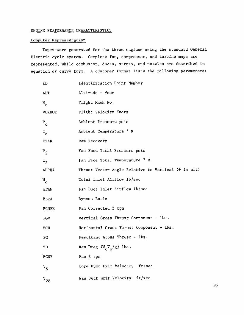
ENGINE PERFORMANCE CHARACTERISTICS
Computer Representa t ion
Tapes w e r e generated f o r t h e t h r e e engines us ing t h e s tandard General
Electr ic c y c l e system, Complete f a n , compressor, and t u r b i n e maps are
represented , wh i l e combustor, duc t s , s t r u t s , and nozz les are descr ibed i n
equat ion o r curve form. A customer format lists t h e fol lowing parameters:
I D
ALIT
M
VOKNOT
0
0 T
ETAR
p2
T2
ALPHA
W
WFAN
BETA
PCNFK
FGV
FGH
FG
FD
P CNF
'8
0
v28
I d e n t i f i c a t i o n Poin t Number
A l t i t u d e - f e e t
F l i g h t Mach No a
F l i g h t Veloci ty Knots
Ambient P res su re ps i a
Ambient Temperature O R
Ram Recovery
Fan Face Tclral P res su re p s i a
Fan Face To ta l Temperature R
Thrus t Vector Angle Relative t o Vertical (+ is a f t )
T o t a l I n l e t Airflow l b / s e c
Fan Duct I n l e t Airflow l b / s e c
Bypass Rat io
Fan Corrected % rpm
Vertical Gross Thrust Component - l b s a
Horizonta l Gross Thrust Component - l b s .
Resu l t an t Gross Thrust - l b s . Ram Drag (WoVo/g) l b s .
Fan % rpm
Core Duct Ex i t Veloci ty f t / s e c
Fan Duct Ex i t Veloc i ty f t / s e c
95
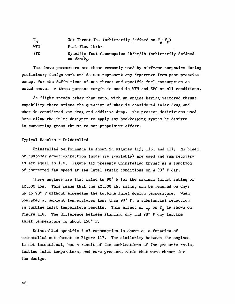
N e t Thrust l b . ( a r b i t r a r i l y def ined as T -F ) FN g D WFPl Fuel Flow l b / h r
SFC S p e c i f i c Fuel Consumption l b / h r / l b ( a r b i t r a r i l y def ined as WFM/FN
The above parameters are those commonly used by a i r f r ame companies dur ing
pre l iminary des ign work and do not r ep resen t any depa r tu re from p a s t p r a c t i c e
except f o r t h e d e f i n i t i o n s of n e t t h r u s t and s p e c i f i c f u e l consumption as
noted above. A t h r e e percent margin i s used i n WFM and SFC a t a l l cond i t ions .
A t f l i g h t speeds o t h e r than zero, wi th an engine having vec tored t h r u s t
c a p a b i l i t y t h e r e arises t h e ques t ion of what is considered i n l e t drag and
what is considered r a m drag and a d d i t i v e drag. The p resen t d e f i n i t i o n s used
he re a l low t h e i n l e t des igner t o apply any bookkeeping system h e d e s i r e s
i n convert ing g ross t h r u s t t o n e t propuls ive e f f o r t .
Typical Resu l t s - Unins t a l l ed
Un ins t a l l ed performance is shown i n F igures 115, 116, and 117. No b leed
o r customer power e x t r a c t i o n (none are a v a i l a b l e ) are used and ram recovery
is set equal t o 1.0. F igure 115 p r e s e n t s u n i n s t a l l e d t h r u s t as a f u n c t i o n
of co r rec t ed f a n speed a t sea level s t a t i c cond i t ions on a 90" F day.
These engines are f l a t r a t e d t o 90" F f o r the maximum t h r u s t r a t i n g of
12,500 l b s . This means t h a t t h e 12,500 l b . r a t i n g can be reached on days
up t o 90" F without exceeding t h e t u r b i n e i n l e t des ign temperature. When
operated a t ambient temperatures less than 90" F, a s u b s t a n t i a l r educ t ion
i n tu rb ine i n l e t temperature r e s u l t s . This e f f e c t of T on T is shown on
Figure 116.
i n l e t temperature is about 150' F.
0 4 The d i f f e r e n c e between s tandard day and 90" F day t u r b i n e
Unins ta l led s p e c i f i c f u e l consumption is shown as a func t ion of
u n i n s t a l l e d n e t t h r u s t on F igure 117.
is not i n t e n t i o n a l , but a r e s u l t of t h e combinations of f a n p r e s s u r e r a t i o ,
t u rb ine i n l e t temperature , and core p re s su re r a t i o t h a t w e r e chosen f o r
t h e design.
The s i m i l a r i t y between t h e engines
96

Fan speed/f low c h a r a c t e r i s t i c s f o r t h e engines are shown on Figure
118.
The performance d a t a presented are v a l i d over t h e des i r ed range of
Sca l ing e f f e c t s 80% t o 150% of t h e engine design t h r u s t of 12,500 l b s .
over t h i s span are judged t o be n e g l i g i b l e r e l a t i v e t o performance.
INSTALLATION AERODYNAMICS AND ENGINE STABILITY
Configurat ion S e l e c t i o n
The d e s i r e t o i n v e s t i g a t e p o t e n t i a l i n s t a l l a t i o n aerodynamic and
crossf low e f f e c t s n e c e s s i t a t e d t h e establ ishment of engine i n l e t d i s t o r t i o n
and recovery o b j e c t i v e s a g a i n s t which t o eva lua te engine performance. This
work is in tended only t o show t y p i c a l e f f e c t s of an assumed i n s t a l l a t i o n
having t h e ass igned c h a r a c t e r i s t i c s , which are reasonable based on the
l i m i t e d informat ion a v a i l a b l e f o r t h i s type of i n s t a l l a t i o n . As an a c t u a l
design evolves during a i r f rame/engine i n t e g r a t i o n i n an a c t u a l development
program, s u b s t a n t i a l t e s t i n g , s t a t i c , wind tunnel , and f u l l scale would be
requi red t o a s s u r e an adequate des ign .
The assumed conf igu ra t ion has t h e fol lowing f e a t u r e s :
6 engine pod
Gimbaled engine (-15' through, +45")
Synchronized v e c t o r angle
120°/second s l e w rate on vec to r ing
Hydraul ic a c t u a t i o n
Upper and lower double hinged doors
Engine i n l e t bellmouth rad ius varies ( r ad ius / f an t i p diameter
0.15 - 0.2)
Three views of the pod inco rpora t ing these f e a t u r e s are shown on Figure
119. I n l e t and exhaust doors i n t h e open, c losed , and t r a n s i t i o n modes are
shown on Figure 120. Details of t he i n l e t and exhaust doors are shown i n
Figures 121 and 122.
concept of t h i s t ype ,
Figure 123 shows a t y p i c a l a i r p l a n e using an i n s t a l l a t i o n
97

I n l e t Charac t e r i s t i c s
I n l e t recovery and d i s t o r t i o n parameter o b j e c t i v e s f o r t he wors t
engine i n the pod (usua l ly t h e f i r s t o r l a s t ) are presented as a func t ion
of i n l e t v e l o c i t y r a t i o ( f rees t ream v e l o c i t y / f a n i n l e t v e l o c i t y ) and
engine v e c t o r angle .
F igure 125 shows d i s t o r t i o n parameter,
Reference l i n e s on both of t h e s e curves show extremes which might be
encountered over a wide range of engine power s e t t i n g s a t the maximum
envelope v e l o c i t y of 200 knots . The e f f e c t of power s e t t i n g on crossf low
v e l o c i t y r a t i o is f u r t h e r explored on Figure 126. In spec t ion of t h e s e
f i g u r e s w i l l reveal t h a t a t normal takeoff power s e t t i n g s i n l e t recovery
and d i s t o r t i o n should pose no s e r i o u s problem.
Figure 124 shows i n l e t recovery, PT2/PTo; whi le
('Tmax. 'Tmin. "'~avg e
Method of D i s t o r t i o n Representa t ion
The d i s t o r t i o n e f f e c t s descr ibed above mani fes t themselves i n changes
i n f a n and compressor s t a l l margin, a i r f l o w , and a d i a b a t i c e f f i c i e n c y .
Sca le f a c t o r s f o r t h e s e changes are benerated f o r u se i n modifying t h e
f a n and compressor map c h a r a c t e r i s t i c s as shown on Figure 1 2 7 . Crosswind
d i s t o r t i o n e f f e c t curves used i n genera t ing " i n s t a l l e d " performance d a t a
are shown on Figures 128 and 129.
I
E f f e c t on Performance
Un ins t a l l ed performance is generated wi th a r a m recovery of 1.0, and no
d i s t o r t i o n e f f e c t superimposed on the b a s i c component maps. I n s t a l l e d d a t a
is generated wi th r a m recovery from Figure 124 and f a n and compressor map
modi f ie rs genera ted by t h e procedure as descr ibed above. No customer b l eed
o r power e x t r a c t i o n is included i n e i t h e r case s i n c e t h e engine has no
provis ion f o r t hese .
A s imple way t o o b t a i n an i n s i g h t i n t o p o t e n t i a l i n s t a l l a t i o n e f f e c t s
i s t o compare i n s t a l l e d and u n i n s t a l l e d performance along a t y p i c a l takeoff
t r a j e c t o r y . A t y p i c a l t r a j e c t o r y is pos tu l a t ed on Figures 130 and 131.
This t r a j e c t o r y is based i n p a r t on t h e experiences of Dornier i n ope ra t ing
98

the D0.31 VTOL a i r p l a n e . Power s e t t i n g , a l t i t u d e , t h r u s t vec to r angle ,
and forward speed are presented as a func t ion of d i s t a n c e from l i f t o f f
po in t . The t r a j e c t o r y chosen happens t o be a minimum f u e l t r a j e c t o r y , and
i t i s recognized t h a t a minimum no i se t r a j e c t o r y may be d i f f e r e n t , bu t
e f f e c t on performance should s t i l l be informat ive .
Four p o i n t s are s e l e c t e d from along t h e t r a j e c t o r y , and % t h r u s t is
converted i n t o f an co r rec t ed speed, t h e primary c o n t r o l i npu t .
Corrected f a n speed
- P CNFK
90%
90%
80%
65%
A 1 t i tude Dis tance from A i r speed
v 0 T / O
0 +lo" 0 0
f e e t Thrust vec to r ALT angle
80 +37" 60 K t 350 f t .
100 +45" 80 K t 650 f t .
190 +45" 120 K t 1500 f t .
E f f e c t on gross r e s u l t a n t t h r u s t , f a n s t a l l margin, and t o t a l co r rec t ed
a i r f l o w are shown on Figures 132, 133, and 134 r e s p e c t i v e l y . For t h e
assumptions made, t he i n s t a l l a t i o n e f f e c t s based on a v a i l a b l e informat ion ,
do no t seem t o impose undue r e s t r a i n t s on the engine design. This conclusion
is re in fo rced by experience which has been obta ined dur ing t h e XV5A and
D0.31 f l i g h t test programs. This is not t o say , as previous ly d iscussed ,
t h a t i n s t a l l a t i o n design and e n g i n e / a i r c r a f t i n t e g r a t i o n are going t o be
s imple. S u b s t a n t i a l development component and systems t e s t i n g are
going t o be requi red t o achieve a s a t i s f a c t o r y i n s t a l l a t i o n . The r e s u l t s
of t h e p re sen t i n v e s t i g a t i o n i n d i c a t e only t h a t t h i s should not p re sen t a
b a r r i e r problem, b u t r e q u i r e s development of f an and compressor wi th
adequate s t a l l margin and d i s t o r t i o n to l e rance .
TRANSIENTS AND STARTING CHARACTERISTICS
S tart i n 2
S ince t h e engine has b l eed d r iven accesso r i e s and no requirement f o r
customer power e x t r a c t i o n , t h e r e is no engine gearbox and d r i v e a v a i l a b l e
f o r u se wi th a convent ional starter, The s e l e c t e d s t a r t i n g system i s of
99

t h e a i r impingement type.
nozz le and r o t o r is p res su r i zed w i t h air which is d i r e c t e d through a series of
s m a l l s l o t type nozzles toward the b lades . The torque thus produced is s u f f i c i e n t
t o a c c e l e r a t e t he engine t o self s u s t a i n i n g f i r e speed provid ing s u f f i c i e n t
a i r i s a v a i l a b l e .
model, i t is es t imated t h a t t o achieve t h e fol lowing sequence of events, 1.5 l b / s e c
of starter a i r a t 50 p s i a and 350" F would be requi red t o b r ing the engine
up t o i d l e i n 30 t o 35 seconds.
A manifold above and between t h e high p res su re t u r b i n e
Based on experience wi th t h i s type of starter on one GEJ85
% Core Speed
15%
40%
55%
F i r e
cu tou t
I d l e
S t a r t t i m e p e r engine could be c u t t o 20 t o 25 seconds wi th an i n c r e a s e
The starter a i r r equ i r ed could i n starter a i r q u a n t i t y t o ' a b o u t 2.5 Ib / sec .
be suppl ied by e i t h e r APU o r from bleed from any c r u i s e engines aboard the
a i r veh ic l e .
The 55% i d l e core speed used i n t h e s t a r t i n g t i m e s tudy w a s a r b i t r a r i l y
chosen as being r e p r e s e n t a t i v e .
p r a c t i c e wi th an a i r v e h i c l e des igne r , and w i l l be a ba lance among several
requirements :
Actual i d l e speed w i l l be determined i n
I d l e Emissions - A low i d l e speed makes t h e t rea tment of i d l e
emissions more d i f f i c u l t .
I d l e Thrust - A low i d l e t h r u s t is probably d e s i r a b l e both i n
t h e a i r and on the ground s o t h a t s t a r t i n g t h e l i f t engines does
no t s u b s t a n t i a l l y a l te r t h e a i r c r a f t t r i m .
Acce le ra t ion T ime - Obviously r a p i d t h r u s t response from i d l e
t o max. can be obta ined i f i n i t i a l i d l e i s h igh .
Engine Trans ien t Response
Considerat ion w a s given t o t h e t h r u s t response c h a r a c t e r i s t i c s of t h e s e
engines . The s ta tement of work requi red a 10% t h r u s t i nc rease w i t h i n 0 . 3
seconds a t f a n co r rec t ed speeds above 60%. A l i m i t e d s tudy us ing an e x i s t i n g
100

dynamic model of a two-spool turbofan engine ind ica t ed t h e fol lowing t h r u s t
i nc rease could be achieved wi th in the 0 . 3 second t i m e i n t e r v a l by a t h r o t t l e
b u r s t from t h e ind ica t ed f a n speed:
% Fan Speed
60
70
80
90
% Thrust Increase i n 0 . 3 seconds
16
15
13
11
It should be caut ioned t h a t the 0 . 3 second is no t a t i m e cons tan t i n
t h e usua l s ense , b u t a t o t a l e lapsed t i m e during a t h r o t t l e b u r s t .
t i m e cons t an t s are expected t o be approximately 0.16 t o 0 .2 seconds over
a range of power s e t t i n g s . Addi t iona l work t o more accu ra t e ly and completely
de f ine the t h r u s t response c h a r a c t e r i s t i c has been au thor ized by NASA
and w i l l be repor ted i n t h e NAS 14406 f i n a l r e p o r t .
Engine
As i n many o t h e r system phrameters, i t i s recognized t h a t t h e a i r f rame/
propuls ion system i n t e g r a t i o n a n l o v e r a l l a i r v e h i c l e conf igu ra t ion w i l l
have a very s t r o n g e f f e c t on engine t h r u s t response requirements . The
p resen t work is only a b r i e f look t o achieve some understanding of p re sen t
c a p a b i l i t y and p o t e n t i a l .
101
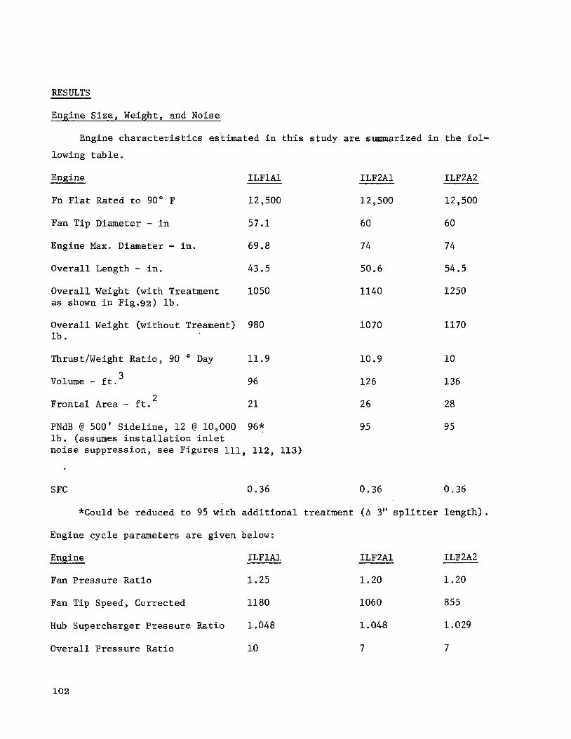
RESULTS
Engine S ize , Weight, and Noise
Engine c h a r a c t e r i s t i c s es t imated i n t h i s s tudy are summarized i n t h e f o l -
lowing t a b l e
Engine ILFlAl ILF2Al ILF2A2
Fn F l a t Rated t o 90" F 12,500 1 2 500 1 2 500
Fan Tip Diameter - i n 57.1 60 60
Engine Max. Diameter - i n . 69.8 74 74
Overa l l Length - i n . 43.5 50.6 54.5
Overa l l Weight (with Treatment 1050 as shown i n Fig.92) l b .
Overa l l Weight (without Treament) 980 l b .
1140 1250
1070 1170
Thrust/Weight R a t i o , 90 Day 11.9 10.9 10
3 Volume - f t .
2 F r o n t a l Area - f t . 96
21
126 136
26 28
PNdB @ 500' S i d e l i n e , 1 2 @ 10,000 96* 95 l b . (assumes i n s t a l l a t i o n i n l e t n o i s e suppress ion , see Figures 111, 112, 113)
95
SFC 0.36 0.36 0.36
*Could be reduced t o 95 wi th a d d i t i o n a l t reatment ( A 3" s p l i t t e r l e n g t h ) ,
Engine cyc le parameters are given below:
Engine
Fan Pressure Rat io
ILFlAl ILF2A1 ILF2A2
1.25 1.20 1.20
Fan Tip Speed, Corrected 1180 1060 855
Hub Supercharger P r e s s u r e Rat io 1.048 1 048 1.029
Overa l l Pressure Rat io 10 7 7
102

T 4 - O F 2500 2000
Bypass Rat io
1 . 3
12.6
1 . 3
1l.6
2000
1 . 3
11.7
Engine Sca le Fac tors
1 / 2
1 .25
S ize -(Diameter/Base Diameter) = Thrust/Base Thrust)
Weight - (Weight/Base Weight) = (Thrust/Base Thrus t )
DISCUSSION OF RESULTS
Noise C h a r a c t e r i s t i c s - E f f e c t on Weight and S i z e
A major r e s u l t of t h i s s tudy w a s t he es tab l i shment of t h e compromises
requi red t o meet t h e s t r i n g e n t n o i s e requirements .
weight and engine diameter .
wi th t h e a i m of reducing t h e impact on weight and s i z e ; a shrouded g r a p h i t e /
epoxy fan , composite compressor b lades and acous t i c pane l s , a s h o r t h ighly
Most a f f e c t e d were engine
Many advanced technology f e a t u r e s were appl ied
loaded compressor us ing cas ing ,reatment, a r eve r se flow combustor, and a h ighly
loaded f a n t u r b i n e . The achieverrent of a t h r u s t t o weight r a t i o of twelve is
encouraging i n l i g h t of t h e fol lowing.
Resul t s are based on a prel iminary design of a l l components and inc ludes
Thrust t o weight r a t i o is quoted on a 90" F day. a development weight adder .
A s u b s t a n t i a l a c o u s t i c t rea tment weight i s included.
On a b a s i s of more t y p i c a l comparison, no development adder , no a c o u s t i c
t rea tment , and on a s tandard day non-f la t r a t e d t h r u s t t o weight r a t i o would
be i n the range of 14-1 /2 .
design f an p res su re r a t i o of 1.25, a level d i c t a t e d by cons ide ra t ion of t h e
need f o r low j e t no i se .
This i s a r e spec tab le f i g u r e f o r an engine wi th a
Engine Performance
Resul t s of t h e Task I paramet r ic s tudy ind ica t ed t h a t , p r imar i ly because
of t h e s h o r t mission use , b a s i c engine SFC w a s r e l a t i v e l y unimportant as a
measure of s u c c e s s f u l des ign . Emphasis w a s t h e r e f o r e p laced on achiev ing ade-
qua te s t a l l margin, compactness, s i m p l i c i t y , fewer p a r t s , ease of assembly, and
103

p o t e n t i a l low manufacturing c o s t .
loaded f a n t u r b i n e were two ins t ances where performance w a s t raded f o r engine
volume,
i ng increased cool ing a i r f o r the ILFlAl w a s accepted t o achieve a s impler and
lower c o s t bucket design.
The high t i p speed compressor and h ighly
A reduced l e v e l of high p res su re t u r b i n e cool ing e f f e c t i v e n e s s requi r -
Fan Tip Speed E f f e c t
The primary purpose of completing the pre l iminary des ign on the ILF2A2
w a s t o achieve a comparison i n terms of weight , n o i s e performance, and s i z e
re la t ive t o the ILF2A1. The only d i f f e r e n c e i n t h e s e two 1 . 2 f a n p re s su re de-
s i g n s being t h a t t h e ILF2A2 has a 25% lower f an t i p speed and an a d d i t i o n a l low
p res su re t u r b i n e s t a g e due t o t h e reduced wheel speed. The r e s u l t s of t he s rudy
based on s t anda rd General Electr ic procedures i n d i c a t e t h a t t he lower speed f a n
has n e g l i g i b l e n o i s e advantage wh i l e s u f f e r i n g an i n c r e a s e i n engine l eng th ,
engine weight , and i n number of p a r t s a
I n s t a l l a t i o n Aerodynamics
The r e s u l t s of t h e i n s t a l l a t i o n s tudy ind ica t ed t h a t engine-airframe i n t e -
g r a t i o n w i l l be an important p a r t of any a i r v e h i c l e development program.
technology d a t a covering i n s t a l l a t i o n c h a r a c t e r i s t i c s of tu rbofan l i f t engines
are very l i m i t e d . Design requirements relative t o t r a n s i e n t response and s t a l l
margin must be pos tu l a t ed f o r t h e p re sen t s i n c e they are dependent on ope ra t ing
method and takeoff t r a j e c t o r y s e l e c t i o n . I n t h e case of takeoff t r a j e c t o r y
alone; t h i s may be a func t ion of requi red n o i s e ground contour . A new f i e l d of
i n s t a l l a t i o n aerodynamics and engine s t a b i l i t y a n a l y s i s r e q u i r e s ex tens ive analy-
t i c a l and experimental i n v e s t i g a t i o n .
Basic
Commercial Design Features
Most l i f t engine designs completed i n t h e p a s t have been f o r m i l i t a r y appl i -
c a t i o n s wi th reduced l i f e requirements , no n o i s e o r emission l i m i t s , no contain-
ment requirements, and have d i f f e r e n t needs relative t o f i r e s a f e t y , r e l i a b i l i t y ,
and s i m p l i c i t y . An important r e s u l t of t he p re sen t designs w a s t o determine t h e
e f f e c t of s t r ic t adherence t o FAR P a r t 25 and P a r t 33 requirements on a commer-
c ia l turbofan l i f t engine. F i r e s a f e t y requirements were m e t w i t h u s e of auto-
matic d r a i n s , f i r ep roof cases, and shrouding of f u e l and hydrau l i c l i n e s i n f i r e
104

zones. R e l i a b i l i t y requirements were m e t by use of dua l i g n i t i o n l e a d s , e x c i t e r s ,
and i g n i t e r s . Fan b lade containment w a s provided t o prevent damage t o ad jacent
s t r u c t u r e s by providing f o r complete containment of a f a i l e d b l ade .
Addi t iona l s a f e t y i n t h i s regard is obta ined by use of a continuous t i p
shroud.
t he combustor. The o v e r a l l r e s u l t s presented r e f l e c t cons ide ra t ion of a l l t h e s e
commercial des ign requirements p lus a r ecogn i t ion f o r t h e need of s i m p l i c i t y
and t h e u s e of a few p a r t s as poss ib l e .
Reduced exhaust emissions w i l l be achieved through d e t a i l e d des ign of
CONCLUSIONS AND RECOMMENDATIONS
The i n s i g h t s gained and t h e experience der ived through t h e pre l iminary de-
s i g n completed on the t h r e e commercial d i r e c t l i f t tu rbofan engines l e a d t o
t h e fol lowing major conclusions:
A n o i s e level of 95 PNdB a t 500' s i d e l i n e f o r 12 engines ope ra t ing
a t 10,000 l b . t h r u s t each is p ro jec t ed although t h e r e are uncer ta in-
ties which r e q u i r e fT-rther exp lo ra t ion .
Commercial design requirements of f i r e s a f e t y , containment, and reli-
a b i l i t y can be m e t by proper a t t e n t i o n t o these needs dur ing prelim-
i n a r y and d e t a i l e d component design. A l i f t t o weight r a t i o of 1 2 / 1
based on t h e 12,500 l b . maximum r a t i n g is p ro jec t ed f o r a l i f t turbo-
f a n engine meeting t h e s e requirements i n t h e e a r l y t o mid 1980's.
A s h o r t r e l a t i v e l y s imple t compact engine having a s m a l l number of
p a r t s can be designed us ing a reverse l i n e r flow combustor combined
wi th an advanced compressor and h ighly loaded fan t u r b i n e .
Another va luab le a spec t of t h e c u r r e n t work is t h e i d e n t i f i c a t i o n of areas
of technology i n which voids ex i t s , and t h e r e f o r e appear t o have p o t e n t i a l f o r
development of new knowledge and improved des ign techniques.
Source n o i s e r educ t ion techniques i n the 1.2 t o 1 . 2 5 ' f a n p res su re
r a t i o range,
Treatment of combus t o r and t u r b i n e n o i s e
105

Degree of compressor and f a n i n l e t r a d i a t e d n o i s e heard i n t h e rear
quadrant .
E f f e c t of crossf low v e l o c i t y on f an and j e t no i se .
E f f e c t of t r a j e c t o r y on ground n o i s e contours inc luding r e f l e c t i o n
e f f e c t s .
Addi t iona l design s t u d i e s i n s e v e r a l areas sugges t themselves as being of
f u t u r e importance t o a i r c r a f t system c h a r a c t e r i s t i c s .
Engine emission s tudy ( i n i t i a l work being accomplished under NAS14406).
Manufacturing c o s t reduct ion and va lue engineer ing design e f f o r t under
(NAS14406).
e
Evalua t ion of louvered vec to r ing and a l t e r n a t e i n l e t design concepts .
More d e t a i l e d s tudy of o p e r a t i o n a l requirements relative t o engine
a i r c r a f t c o n t r o l i n t e g r L i i o n , ground and -air s t a r t i n g , and engine
t r a n s i e n t ope ra t ion .
The pre l iminary designs under l ined t h e needs f o r a n a l y t i c a l and experimental
development work i n several component areas:
Techniques f o r fan and primary s'ource no i se reduct iot i and suppress ion
I n s t a l l a t i o n aerodynamics f o r compatible a i r f rame/engine design
Composite b l ade , shroud, and d o v e t a i l design and cons t ruc t ion
5 s t a g e , 1O:l p/p core compressor
Low emission reverse l i n e r flow combustor w i th 2500' F T
Very h igh ly loaded f a n t u r b i n e
A l l e l e c t r o n i c f u e l c o n t r o l s
4
106

SYMBOLS
La t in
A
A
ALT
ALPHA
BETA
W
cf
cF
C
2 C
C
‘d
D
D ,D.F. -f
ETAR
FGV
FGH
V
FG
FF
FD
FN
H
h
i
2 Flow area, Et.
wetted area - f t .
A l t i t u d e , f t .
Thrus t v e c t o r angle , relative t o vertical (+ is a f t )
Eypass r a t i o
F r i c t i o n drag c o e f f i c i e n t
Chord, i n
Nozzle flow c o e f f i c i e n t
Axial v e l o c i t y
Nozzle v e l o c i t y c o e f f i c i e n t
Drag c o e f f i c i e n t
diameter , i n
D i f fus ion f a c t o r
Ram recovery
Vertical gross t h r u s t Component - l b
Hor i zon ta l g ross t h r u s t component - l b
Resu l t an t gross t h r u s t - l b .
P res su re drag f a c t o r
Ram drag (Wo Vo/g) - l b .
N e t t h r u s t , l b . ( a r b i t r a r i l y def ined as FG - FD)
G r a v i t a t i o n a l cons tan t
Height , i n
Enthalpy, Btu / lb
Inc idence angle deg
2
f t . /sec .
107
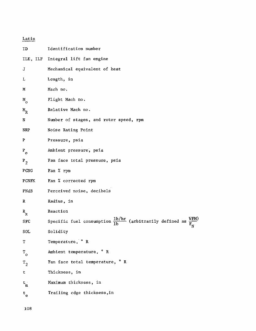
L a t i n
I D I d e n t i f i c a t i o n number
ILE, ILF I n t e g r a l l i f t f a n engine
J
L
M
M 0
5 N
NRP
P
P 0
p2
P CNG
PCNFK
PNdB
R
Rx
S FC
SOL
T
T 0
T2
t
t m
te
108
Mechanical equ iva len t of hea t
Length, i n
Mach no.
F l i g h t Mach no a
Relative Mach no.
Number of s t a g e s , and r o t o r speed, rpm
Noise Rat ing P o i n t
P res su re , p s i a
Ambient p re s su re , p s i a
Fan f a c e t o t a l p re s su re , p s i a
Fan % rpm
Fan % cor rec t ed rpm
Perceived no i se , dec ibe l s
Radius, i n
React ion
S p e c i f i c f u e l consumption Pb/hr ( a r b i t r a r i l y def ined as - FN l b
S o l i d i t y
Temperature, R
Ambient temperature , R
Fan f a c e t o t a l temperature , R
Thickness, i n
Maximum th ickness i n
T r a i l i n g edge th ickness , i n

L a t i n
U
vO
v28
VOKNOT
W
0 W
WFAN
W F M
xf
Greek
Wheel speed, f t / s e c
F l i g h t v e l o c i t y , f t / s e c
Core duct e x i t v e l o c i t y , f t / s e c
Fan duct e x i t v e l o c i t y , f t / s e c
F l i g h t v e l o c i t y , knots
Weight flow, l b / s e c
T o t a l i n l e t a i r f low, l b / s e c
Fan duct i n l e t a i r f l o w , l b / s e c
Fuel Flow, l b / h r
Deviat ion c o r r e c t i o n f a c t o r , deg.
1 c1
@l
62
@In
Y
r
A
6
'ad
' P x w
Absolute i n l e t a i r angle , deg.
Relative i n l e t a i r angle , deg.
Relative d ischarge a i r angle , deg.
Stagger angle , deg.
S p e c i f i c h e a t r a t i o
Swi r l ang le
Incremental change
Deviat ion angle , deg. and i n l e t p re s su re c o r r e c t i o n
Adiaba t ic e f f i c i e n c y
P o l y t r o p i c e f f i c i e n c y
Wave l eng th
l o s s c o e f f i c i e n t
109

Greek
P Camber
c Sum of
(J S o l i d i t y
e I n l e t temperature c o r r e c t i o n
Y Turbine loading
Subsc r ip t s
1 b lade row i n l e t
2 b l ade row e x i t and i n l e t s t a t i o n
C compressor
EX exi t
F f a n
H hub
P p i t c h
R re l a t ive
T t i p
0 ambient
4
8 co re nozz le t h r o a t
54 low p res su re t u r b i n e i n l e t
55 low p res su re t u r b i n e ex i t
28 f a n nozz le t h r o a t
high p res su re t u r b i n e r o t o r i n l e t
Supe r sc r ip t s
- b a r average
prime' compressor i n l e t
110

Table I. Turbine Cooling Technology.
= 1650' F TBulk (Using Simplest Method)
High Pressure Low Pressure T4 O F Technology Turbine Turbine
2800 Adv. Impingement Film Vane and Rotor Stage 1 and Stage 2
25 00 Impingement - T/E Holes Vane and Rotor 1st Stage Only
2200 Convection - T/E Holes Vane and Rotor 1st Stage Vane Only
1850 Convect ion Vane Only None
111

Table 11. Turbine Cooling Summary.
(Percentages of Core Compressor Flow)
E
High P res su re Turbine Low Pressu re Turbine
T4 F Leakage Vane Blade Leakage Vane Blade 1 Vane 2
2800 P/P 5 1.8 1.8 1.8 3.0 1.4 1.3 1.0
7 1.8 2.0 2.0 3.0 1.3 1.2 0.8 10 1.8 2.2 2.2 3.0 1.2 1.1 0.6 15 1.8 2.6 2.6 3.0 1.0 0.9 0
2500 P/P 5 1.8 2.0 2.0 3.0 1.6 1.6 0
7 1.8 2.5 2.5 3.0 1.2 1.2 0 10 1.8 3.0 3.0 3.0 1.0 0 0 15 1.8 3.5 3.5 3.0 0.5 0 0
2200 P/P 5 1.8 1.4 1.4 3.0 0.8 0 0
7 1.8 1.6 1.6 3.0 0.5 0 0 10 1.8 1.9 1.9 3.0 0 0 0 15 1.8 2.3 2.3 3,O 0 0 0
Blade 2
0.6 0 0 0
1850 P/P 5 1.8 1.0 0 3.0 0 0 0 0
7 1.8 1.0 0 3.0 0 0 0 0 10 1.8 1.0 0 3.0 0 0 0 0 15 1.8 1.0 30 3.0 0 0 0 0
112

m m.c a,
N O Q 5
m G)
N O a s
Q.2
* a 3
M X > a e 3
~ ~ o o ~ m m o w d d m m ~ ~ ~ m m t - b m a m m m w w c 0. m. t-. m. p: w ro 4 m d m m ~ ~ o o ~ ~ ~ t - m o . + ~ m ~ d m m ~ m m . . . . . . . . . . . . . . . N N N N N N N N N N N N N N N N d N N N
tld \ PI
E
* E 0
3 0 0 0 0 m o m m m * m m c c m m d N d d d
0 0 3 0 0 0 m o o 0 u3 N - 0 0 N m
d N N %
a, m m U
113
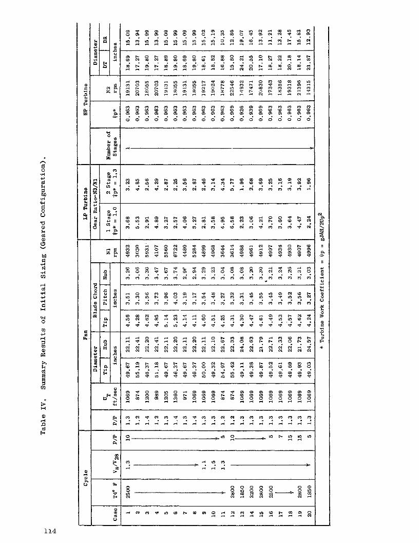
++ a 3
n
.d c, cd k
U a, k cd a, 0 W
u h:
w =." H
a rl P (6 E
PI \ PI
Fr
P)
V m
114

k 0 c, 111 s P
u
rl h a a, 111 k a, 3 a, tz a a, k cd a, 0 I
R
j
2l
a,
cd E
E; a m N o V ) N mt- N F m N rl M Nu2 r l v NV: rl t-
109 o m * m w 5 g: e m m w m wv)
loe o m v t-e t- o m N v) M N m r l l o r n e m (1 w m wv) d 7 N rl In NCO r l l o N U m m
rl lnrl rl t-
115
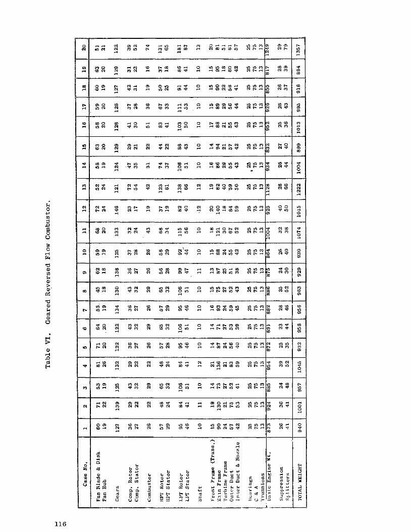
k 8 c,
P
u
3
$ f-l
Fr a a, tll k a, 3 a,' el
a Q) k cd a, r3
H 3- a,
I 4 P cd E
I
0 m m
o m t- W d N
rl
4 k O 0 - 0 d 0 0 ern
a a E E 0 0 0 0
. .
116

Table V I I . I n t e g r a l L i f t Engine.
Component
Fan Sec t ion Blade Disk Supercharger Nose Spinner S p l i t t e r Nose T i p Shroud
Compressor IGV Stg . 1 Vane Stg . 2 Vane Stg . 3 & 4 Vanes OGV Stg . 1 Blade S tg . 2-5 Blades
Fwd. C a s e Rear C a s e Fwd. Ro ta t ing S e a l s Vane. T i p S e a l s
Spool
S tgs . 1 & 2 S tgs . 3 - 5
Combustor L ine r Middle Liner Outer L ine r Nozzle Manifold
Turb ine .
Stg . 1 Vanes S tgs . 2 - 4 Vanes S tgs . 1 - 2 Bucket S tg . 3 Bucket S tg . 4 Bucket S tg . 1 Disk LP Spool HP Conica l S h a f t s LP Conica l S h a f t s HP Turbine T ip S e a l s HP Turbine T i p S e a l s
Vane S e a l s
LP S h a f t S e a l s Main S h a f t
S t a t i c S t r u c t u r e s Fwd. Frame S t r u t s A f t S t r u t s Fwd. Outer Bear ing Support & Rota t ing S e a l s S t a t i c S e a l s
Fwd Cowling Fwd O u t e r Fan Duct R e a r Outer Fan Duct (2) Fwd Inner Fan Du (3) S p l i t t e r Rings A f t Inne r Fan Duct Af t Frame
Inne r and Outer Frame Support
a te r ia l
Graphite/Epoxy Ti77XD
Glass/Epoxy Glass/Epoxy Graphite/Epoxy
17- 4PH
Graphi teDpoxy w i t h 321 SS Tube 224T62 I N 7 1 8 I N 7 1 8 Graphi t e/Epoxy T i 6A1-4V Ti77XD 224-T62 17-4PH 321SS
Poly imide Nickel/Graphite
Has te l loy X IN625 I N 7 1 8 H a s t e l l o y X Inco 600
W509 Rene 120 Ni76XB Rene 120 Rene 77 N i 7 5 X D Ni75XD I N 7 1 8 IN718
509 Has te l loy X
Has te l loy X
Has te l loy & 17-4PH 4340
6061 T6 I N 7 1 8 4340
224-T62 & ' Gl/Gr/Pl S e a l Glass/Epoxy
6061-T6 & 5052H32 Inco 625 Inco 625
6061-T6 Aluminum
Composite Layup Forging Cas t ing
o ld ing Molding Composite Layup
Chopped F i b e r Molding , C a s t i n g
Punched & Brazed Cas t ing Composite Layup Forging Forg ing Cas t ing Cas t ing F.W. Ring
Molded i n PI/Glass Honeycomb
Sheet Shee t Shee t & Cas t ing Shee t & Cas t ing Turbine
Cas t ing C a s t i n g Cas t ing Cas t ing Cas t ing p&I Forging PM Compact wb Compact
Compact Cas t ing wi th Brazed Ring Honeycomb Brazed t o
Forged Rings. Honeycomb Brazed t o
Forged Rings. Honeycomb Brazed t o Cas t ing Forging
Cas t ing & Sheet Metal Forging
C a s t i n g w i t h
Composite Lay-up
Forging wi th Monocoque Bonded S t r u c t u r e
Brazed Monocoque S t r u c t u r e Brazed wi th Monocoque
S p l i t t e r & OD Shroud
Composite S e a l
arks
Development T i A l loy
Urethane Coat ing Urethane Coat ing
C e n t r a l Tube S e c t i o n ova l
LE FOD P r o t e c t i o n
Codep. Coated Codep Coated Codep Coated Codep Coated
Sound Suppress ion Pane l s
Bonded t o S t r u t s
117

Table VIII. Fan Design Parameter Summary.
Design Parameter
Flow R a t e ; l b / sec
Spec i f i c Flow ; lb/sec- f t2
Pressu re R a t i o
E f f i c i e n c y , Tlad(qp), %
T i p Speed, f t / s e c
S t a l l Margin, %
Bypass Ra t io
I n l e t 8 a d i u s R a t i o
I n l e t Mach Number
E x i t Mach Number
Rotor T i p S o l i d i t y
Rotor Aspect Ra t io
OGV Aspect R a t i o
Number of Blades
Number of OGV 's
ILF 1A 1
588.3
42.5
1.25
87.0(87.3)
1180
18.5
12.6
0. ' 7 1
0.624
0.465
1.0
3.25
5.6
40
80
! ILF2A1
653.2
42.5
1.20
87.6(87.8)
1060
18.0
11 -5
0.468
0.624
0.50
1.0
3.9
5.6
48
80
ILF2A2
653.2
42.5
1.20
88.2(88.4)
855
18.0
11.5
0.468
0.624
0.55
1.0
2.9
4 .2
36
70
TF39 Comp. (Stage 1)
396 a 3
40.0
1 - 2 5
88.2(88.5)
1100
20.0
---
0.361
0.565
0.581
1 .0
3.25
3.5
25
36
118

0 0 0 0 0 0
0 0 0 0 0 0
O d N N O N
c o N c o r l N r l
c o o c o N d N b b b
M N M 0 0 0 0 0 0
0 0 0 0 0 0
* I . e * *
. . O . . . M c D b 0 0 0
0 0 0 I p J P X % I M N * LO 0 0 0 O R 0 0 a . I I d o o l o . 0 0
M d
T I a ld d m a d cd
. . e . . . . . I ( 0 0 0 I O 0 0 . e a . . .
0 0 0 l o 0 0 m
N O O M 0 0 0 M N t . .
. . * 0 0 0 * b d * . .
0 0 0 N r l d d r l
m 0 .r(
6 d h a 0 k a, 4 k e, M k cd s 0 k e, a 5 01
e . . - . - . e .
d o 0 I i o o
0 0 L O O
O N . e
I
0 0 0 0 0 0
d r l M . . a
0 0 0 0 0 0
N r l O * . *
I I
0 k e, 4
3 cr I I
* . e
L O O N M M N
P d cd
I l o o 0 I 0 0 0 I I
2 cr d
o m l o . e .
N Q ) M N r l d
0 0 0 ' 3 Y ' o . pc"
H
e, rl P d E
. . e
0 0 0
$ % g l o m o o o c o o c o w o c o w
. . a 0 . .
A 0 0 I d 0 0 k 0 c, 0 !x
k 0 c, cd c, cJ2
119

0 0 0 0 0 0 d d d 0 0 0
0 0 0 0 0 0 d d d 0 0 0
0 0 0 0 0 0 A d d 0 0 0
0 0 0 . . e
8 8 XI d d d 0 0 0
0 \
a, c, n a
a, a 1 d
0 u 2 v
h k
m 8 M E: .rl a cd d
a a
3 3 01
k M cd .rl n k 0 -P 0 a, L=- k a, M k cd
k Q, a 5 VI
a r: cd
5
3
2 3
pc"
Er d
H
l-4
0 i-i P cd E-c
. . a
0 0 0 0 - 0
0 0 0 rn a, .rl k a, m Lo co
.e
0 \ c,
0 k 4 k cd d 5 0 k .rl u .. z 2 d E: cd
W b
Lo ?
.. 0 4 c, cd m c, 0 a, a m 4
0 W
. O
rn a, a cd d a d 2 -
m a, 4 k a, m Lo co
.. 0 \ c,
0 k 4 k cd d 1 0 k .rl u .a
2 9 .A d
a, si
b N m N
.. 0 .rl c, cd m c, 0 a, a m 4
N bc
e *
rn a, a cd d a 0 x -
d cd *rl 0 a, a m .. 0 \ c,
d cd .rl L) a, a m .. a, E: 4 d rj cd a, si
W bc N
m
.. 0 .rl c, cd m c, 0 a, Q m 4
0 d
.. m a, a cd d a
i -
Lo CD
0 0 0 0 0
0 0 0 0 . e . \ o o o c ,
W W % . .
0 k 4 k
b c w l n c d Q , d W d
. o a ' - j
b d b 0 N N k
.rl u .. a, r: .rl
m c o d d L o m C n r j . . . a N c o M O d d N Z
O W 0 o m 0 m b c w 0 0 0
o w 0 O d O b c o u 3 0 0 0
0 0 0 . . e
o b c w 0 0 0 b W L o 0 0 0
0 0 0 . * *
0
2 c, . e .
0 0 0
W d N b 0 c o O l b L o
N d Q ,
b W 0 d
. . . e ) . . d 0 d
I
h k c, a,
$ a, a cd d
k a, M k (6 s
. L ) k a, a 7 m
a
h k c, a,
s 3 a,
d a r: cd Er
N d d m o b . . . d W b m c v m
0 0 0 Lo
W b c d
d % % 0 . . .. m m m
0 .rl c, m c,
L o c o d 0 O d W a , m W d Q
0 . e r n d d N 4
O W C D O N 0 o w c o d 0 O N
0 .a
W C D O N b c r l d m m
o m d O L o W O N 0 b
k 0 c, (d c, u,
!3 c, cd c, m
a, bn cd c, cI1
k 0 c, 0 m
120

0 0 0 0 0 0
O d N ( l e .
0 0 0 0 0 0
N O N e o n
W M
x a " M c o b 0 0 0
O W " / w : l / 0 0 0 W M * 0 0 0
b - w m o d e M N M 0 0 0
0 0 0 . e .
o w d i w o d i d d c u 0 0 0
0 0 0 m e *
h k
Ei m M F: .rl a cd l-i F9 a F: cd 111
k M cd .rl
k 0 c, 9 a, 3 k a, ha k cd
k a, a 7 m a F( cd G cd Fr
9
n
4
2 3
x"
G
H
a,
cd E
d d d l d ' d d l w c n w o w w O N 0
d d N . . e I b
. 0 .
0 0 0 . . e
0 0 0 0 0 0 ~ 0 0 0 ~
N d b l o o o l 0 0 0
0 0 0 d d d
0 . . U-J 0
.r(
cd
a 0 k a, c k a, M k cd s u k a, a 5 VI
E
. . . N Q N N d
'I U-J 0 .rl E cd r: h a 0 k a, c 3 R
0 Q ) N O d m o w w o b - w O M N o w w . . . d o 0
. . a
d o 0
0 0 0 0 0 0
0 0 0 0 0 0 0 0 0 o m 0 j;;l Q g j
0 0 0 0 0 0
. e .
d d M . e .
N d O I I
5GJ m a ,
R
0 0 0 . . . 0 0 0 . . . C \ I W ~ W d M M M C U
c n d d . . I .
b d m w w o m m w
0 N
w w w 0 0 0
M 2 0 * e *
d H
p;' \
d ez
O N w o w w d o 0
O M N
0 . e
o b - ( 9 O M N o w w d o 0
. e 0
o w c a o w w O b *
0 . I )
d o 0
k 0 c,
2
k 0 c, cd c, m
k k 0 0 c, c, cd 0 c, ez cn
a, M cd 5, m
121

d d d 0 0 0
0 0 0 . . . rn
a, .rl k a, J m u
\ a,
c,
r l d d 0 0 0
0 0 0 - 0 . n a
a, a 3 d
$ u v
A k
m 1 M E: a cd
v-4
d a a El cd rn
k M cd .rl R k 0 c, 0 a,
k a, M k cd c 0 k a, a =r m a E: cd
Fi
?
9 Fr
2 Fr
x"
E! 8 a,
rn a, .rl k a, m In ED
.. .? c,
0 k 4 k cd d 3 u k .rl u .. a, E: -rl d rj cd a, z
d 0 d
0 4 0 O E D 0 M d t o 0 0 0
0 0 0 0 0 0 t o t o t o 0 0 0
0 0 0 e * *
u 2 c, . . D
0 0 0
I n E D c u M t o b
3, k c, a,
a, E5 a, a cd d
k a, M k cd s 0 k a, a s 1%1
!3
a
R k c, a,
8 a, a cd rl a 3 Fr
I d d d c 0 0 0 c u c u c u u E :
H . . . d c d c d c
b
M dc to 0
O I n E D O M c u o t o c o
k 0 c, 0 a!
122

O O W o o c o
L O L O - ? - ? a d N d N 0 0 0
h k cd
m M E:
T I a cd d IQ a E: cd
m
k M cd .r4
k 0 c, 0 a, 3 k a, M k of
k a, a 1 m a G cd
s n
5
9 k
s k I$
0
H X a,
nl E Pl
* . e l o 0 0
- ? c o r n O W N O O L O O O O d
0 0 0 * e . . . e
1 0 0 0
0 0 0 0 0 0
. e . m 0 .d
s E: h a 0 k a, 4 k a, M k cd A 0 k a, a 5 m
0 0 0 d d d
O O M O O N O C O L O
r l c o . i .
M W d M N L O o c o m d o 0
. . O
O b W O M N I ? ? ? O c n N o * m
O c o W
d o 0 . e .
m 0 .rl E
h a 0 k a, 4 E: cd Fr
2 I d 0 0
0 0 0 0 0 0
N d O e . .
I I
0 0 0 0 0 0
d r l 0 e . .
e . .
O d b d d d
d r - b
V b c n N a O M N c o c o W
C J w Q I O N r - M b
. . . M * b d m . . . b b W I L O W W
c n W M * - ? N L O L O L O
0 0 0 0 . 0 e . -
1 0 0 0
O b W O M N O C Q W e . *
d o 0
k 0 c, cd c, m
123
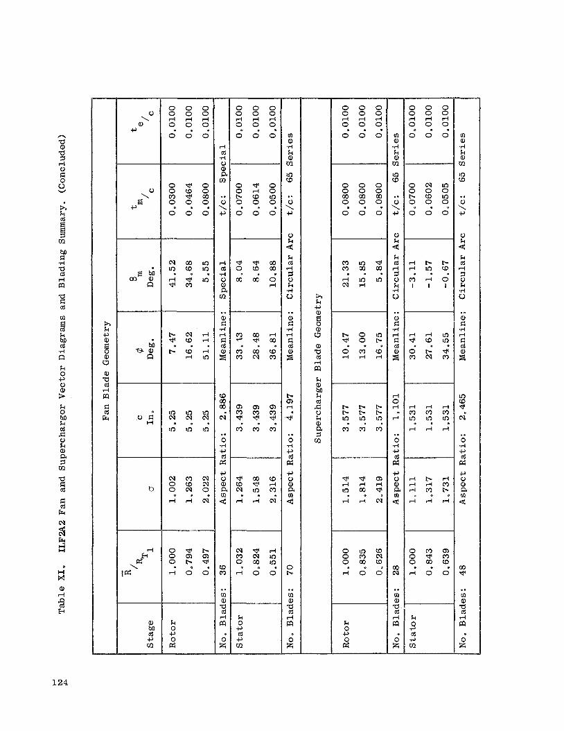
n a a, a I d 0
u W
R k
m B ha c *rl a cd d
a d cd m E cd k M cd
T I la k 0 c, 0 a, > k a, M k cd cl
a, a 5 m a E: cd d cd Fr
m
?I
2 Fr d H x a, d
% E
0 \ a,
c,
0
E\ c,
0 c W
b
a, hl, cd c, m
0 0 0
0 0 0 . . .
O d O O W 0 m d m 0 0 0
0 0 0 e . *
I n W L o
d d I n . e .
b c v d d W d
e . .
I n I n I n N N c v L o L o I n . . .
N M c v O W N o c v o d d c v * . e
O d b o m m
d o 0
h k c, a, 8 s a, 'tl cd d m k
k cd G 0 k a, a 5 m
%
0 0 0 0 0 0 d d d 0 0 0
0 0 0 . . .
0 0 0 0 0 0 c o m c o 0 0 0
. e .
0 0 0
b 0 I n - + O b
O M W d d d
. . .
b b b b b b L o l n L o
e . .
M M W
d o 0
k 0 c, 2
m a, .I4 k a, m In W
.. 0 \ c,
0 k 4 k cd d I 0 k .rl 6>
.. 2
i4
.rl d c cd
d 0 d
rc
.. 0 .rl c, cd pc; c, 0 a, a m c
m cv
.. m a, a cd d m
0 z -
0 0 0 0 0 0 d d d 0 0 0 ~~
0 . 0
0 0 0
o c v l n 0 0 0 b W I n 0 0 0
e . *
0 0 0
d b b d L o W
M d O I l l
. e .
m a, ,rl k a, m Lo W
.. 0 \ c,
0 k .=4 k cd d
k .I4 u 2
. e
a, d
v i d E: cd
8
In CD d cv
.. 0 .rl c, cd p: c, 0 a, a m 4
m * .* m a,
d -2 a 0" z -
124

M aa, n
W M
* a " 0 0 0 1 0 0 0 g C 3 2 0 0 0 0 0 0 0 0 0
o d m O d c u 0 0 0 . . . 1 ::;/ 9 9 9 * d d o 0
0 0 0 0 0
13 . . v d d d l d d d l o o o
d a cu I b
w n
m r - m t o m t o d b d I n I n I n
0 0 0 . . .
N * d I n w c o c u a c u I n d I n
0 0 0 . . .
o w d *win c u t o c u I n d I n
0 0 0 . . .
* o m O b 0 * * I n d * d 0 0 0 . . . e . .
0 0 0
d
\ cu p:
l - i d c v a c u m a b m t o d d
a a t o a t o r - 0 0 0 0 0 0
. . e . . . e . . . . . 0 0 0 1 d d d l o o o
I I I
M T I al n
0 0 0 0 0 0 0 0 0
0 0 0
0 0 0 0 0 0 0 0 0
O d d O d d I I I I
. . . . . . . . . 0 0 0 0 0 0 0 0 0 0 0 0
O d d O d d I I I I
. . . . . .
a m * I n d Q ) w o a I n c o b m a d O O d c u a w * N O I n d O w m I n w w w w w w . . . . . . . . . d N * * o m
I n c u m m a d N t o t o o t o w
. . O . . . w I n m CD In In,
0 0 0 1 0 0 0 e . . . . . 0 0 0 1 . . . 0 0 0 1 0 0 0 . . . I . .
A d d d r l d
m o o b d b a d d . . . . . . . . .
5
d
GE \
d a d d d l d d d l o o o . . *
a, M cd c, m
m * In
k k k 0 0 0 c, c, c, 0 0 0 p: p: pz
k k 0 0
p: c, 0 1 5
125

n a a, I FI .I4 c, G 0 u
W
h k
m I M G .rl a cd d m a FI cd m 5 k M td .I4
k 0 c, c) a, k- k 0 rn m a, k a
u
n
8
2 Fr i i
0
H n x a)
cd b s
m a d d N 0 0 P d b 0 0 0
0 0 0 0 . .
N d a O d m C D d b 0 0 0
0 0 0 . e .
0 0 0 0 0 0 0 0 0 0 0 0
can o o o 0 0 0 C O C D C D . . e
! x $ 0 0 0 0 0 0 . . . Na, * *
A d d d d d
. . . ! \ '
N 0 0 0 !x
0 0 0 0 0 0 0 0 0 0 0 0
n M O N O M N O M N I l l I l l I l l
. . e b;, 0 0 0 0 0 0
.da, . . . . . .
c n . ~ d d c n 0 0 C D a C D b d d d d d d d d
0 0 0 0 0 0 0 0 0 . e . . . . . . .
I t
~ m c , c, c d c , c, c, c, c,
m m m
I 0 0 0 0 0 0
0 0 0 N O N N O N
. e .
. e . " 6 6 1 0 . 0 0
0 0 0 0 0 0 0 0 0 1 0 0 0 . . . . . .
~ 0 0 0 0 0
0 0 0 0 0 0 0 0 0 0 0 0
M M N M N c v I l l I l l
. . . . . .
I
d c, c, k 0 cd p- m c,
m
126

-I 0 0 0 0 0 0 d r l d 0 0 0
0 0 0 e . .
0 0 0
0 0 0 141 41 41
0 0 0 0 0 0 d d d 0 0 0
0 0 0 - 0 .
0 0 0 0 0 0 M m b 0 0 0
0 0 0 . . e
c D * o m d w a m 0 m m m
. e .
0 0 0 0 0 0 d d d 0 0 0
0 0 0 . e m
0 0 0 0 0 0 M m b 0 0 0
0 0 0 . . .
d * * b o a m m b m m *
e . .
m o m m * N b d W d N N
e . .
0 \
a, c,
e . 0
0 0 0
d cd .rl 0 a, a m
0 0 0 0 0 0
* * M m b 0 0 0 0
\ e o .
+ o o o
d cd d
d cd .rl 0 a, a m .. 0 \ c,
d cd .rl 0 a, a m
.. a, c .rl d c cd a, Z
b d
d
.. 0 TI c, cd p: c, 0 a, a m <
0 b
.. m a, -5 cd d m
0 2
0 a, a cn
4 x .. 0 \ c,
0 k < k cd rl 5 0 k .rl u .. 2 3 2
.rl rl
(9 W
0
.. 0 .rl c, c6 p: c, 0 a, a m 4
N I?
.* rn a, -5 cd d m
0 2
0 0 0 0 0 0 c o m b 0 0 0
. e .
0
E' c,
.. 0 \ c, 0 0 0
m 03 w m o w d cd TI 0 a, a m
cQE : n
8 M a, n
.. h k c, a,
$ a, -5 cd d
k 0 c, 0 p:
d
a, Z 3
I 0 0
I c o m m b m m N d m
w % wl m m m d . . .
N N d .. Id 0' d d/ . e . d d d ..
0 -rl c, cd p:
.. 0 .r( c, 6 p: c, 0 a, a rn 4
b
d E
p: \
p:
m m * W d ( 9 m m w 0 0 0
0 . .
* m o W N C D m m w 0 0 0
. . a
0 m .. rn a, -5 c d M d
* c ,
L 2
m m w w o o m m w 0 0 0 e . .
0 0 0
* I?
d
k 0 c, 0 p:
a, M cd c, m
I
127

I 0 0 0 0 0 0 d d d 0 0 0
0 0 0 0 0 0 d d r l 0 0 0
0 0 0 . . .
0 0 0 0 0 0 d r l d 0 0 0
0 0 0 . . . 2 2 2
a, T I k a, m
. . . 0 0 0 VI
a, .rl k a, m Lo (1)
.. 0 \ c,
0
2 k cd d Ef 0 k *r( u .. a, E: .rl d E( cd
2
d m e, 0
.. 0 .d c, cd P; c, 0 a, a m -4
W Q,
m a, a cd d m
0 2 -
m a, .rl k a, m Lo W
a.
u \ c,
0 k 4 k cd d 3 u k .A u .. 2
2
.A d s: cd
ca m m d
.. 0 .rl c, cd P; c, 0 a, a m 4
d I?
.. m a, a cd d m
0 2 I
m 0 .rl k a, m Lo (0
.. 0 \ c,
0 k 4 k cd rl 1 0 k TI u .. a, E: .I4 rl s: (d 0 si
m co rl
d
.. 0 .rl c, cd P; c, 0 a, a m 4
d 03
.o
m a, a 6 d m
-
c*
a, a 5 rl u
u W
h k
ll 5 m M E: a cd d
a E: cd m E (d k M cd -rl Q k 0 c, u a, 3 k 0 m m a, k a E 0 u
Yl
m
2 Fr E!
D
H H w a, rl P td E
128
Lo W
0 0 0 0 0 0
\ . . . + o o o i S g 3
0 0 0 0 0 0 b W l n 0 0 0
0 0 0 0 0 0 b W L o 0 0 0
0 0 0 0 0 0 b W L o 0 0 0
e . .
0 0 0 . . .
0 0 0 . . .
0 0 0
L o d W L o d m . . . 0 0 0 0
O c o b
d d 0 m m m . . .
m d m m m m
h k c, a, E 0 a, r3 a, a cd d
k 0 c, cd c, m
m
b d m c o m b L o o m L o L o L o
. . . . . . l o c o o W L o W
I Q , Q , Q , d r l d 0 0 0
d d d . . .
0 0 0 m c v m c o c o c o m m m c o c o c o m c o c o . . . 0 0 0
e . .
0 0 0
d 0 d b b a m m d r l r l r l . . .
d L o W O W m m m d d d d . . .
L o o m b m W c n m m
W W W O W N . . .
0 0 0 0 . .
0 0 0 . . .
0 0 0
N
k 0 c, cd c, m
* k 0 c, cd c, m
m k 0 c, cd c, m

M m a ,
n
r l 1 0 r l 0 0 1 0
t - m r l . . .
rl
e . .
C D C Q A rl
0 0 0 0 1 0 0
0 0 0 o m 1 0 O d c v . e . . . .
o r l m
m o w O M O r l w w d o 0
. . e I d d d l o o o . . . 0 0 0
. . . 0 0 0
h k
m I M FI .rl a l-d rl Q -5
3
8 rn
k M l-d .r(
n k 0 c, 0 a, >
-k 0 rn rn a, k a
u E si e rl
Fr
0
I-i H H x a, ,-I P cd E
rima C Q C D W r l c v m . . . l - l r l r l
t - c o o O o o o l l O * m
0 0 0
w c v m
. . . . . . I d d d j 0 0 0
c v r l l o C Q m m t - * b L o r n *
. . .
rn 0 .I+
8 E a 0 k a, 4 k 0 c, 0 p:
c v m o N * c v m k - m m o o t - m c o m 0 0 0 3 0 0 . . . . . . . . .
0 0 0 0 0 0
* 0 0 0 0 0 0
O d d
.“;I M x ; ? 1 9 9 9 I I
0 0 0 0 0 0
O d d I I
. . . 0 0 0 0 0 0 . . . O d d
I I
a t - 1 0 m i l ? t- rl C D w m M m O t - r l t - . . .
m o b C O C D L n
I O 0 0 . . . r l r n
I O O C D o m m * a m C Q C Q O r o l o c o
. . .
rl m c v CQ m o o 0 o m
. . e
d r l o . . .
0 0 0 I I
cn c v m 10 m c v m 0 0 0 3
C O r l N c v t - r l m C Q w 0 0 0 . e . . * .
0 0 0
m k 0 c, 0 p:
* k 0 c, 0 p:
rl cv a, M k k l - d o 0 c , c , c, m o 0
p: p:
129

n a a, =r 0 .d c, E: 0 u
W
h k
m 8 M E: .rl a cd d
a E: cd
m
k M cd .d
k 0 + 0 a, > k 0 m 111 a, k
0 u
rn
9
n
2
2 k d
0
U H H x a,
cd E
s
I b
w n
ab;) a n m a ,
d
pzE \
tu p:
M .d a, n
rl E a
\ l-l
!x
a, M cd c, m
e * . . . . m r l m
0 0 0 0 0 0 0 0 0 0 0 0 0 0 0 0 0 0 0 0 0 0 0 0
* b d m m m m d t u m m '00 m m m m b r l m m b
m o 3 b Q l m m m m o 3 m m b 0 0 0 0 0 0 0 0 0 0 0 0
. . . . . . r . . . . e
. . . . . . . . . . . .
o m d b d m m o m o o m C D c o M e . .
M C D C D * . e
b b o o c o b b a . .
0 0 0 ;do" 0 0 0 0 0 0
t u m m t u v m o v m Q l v m Q l b M b o l d v o 9 N o l n m Q l m m Q l W b ~ l m b
S 1 . D
Q l m m * e * . e .
0 0 0 0 0 0 0 0 0 d d d d tu m v k k k k 0 0 0 0 c, c, c, c, cd cd cd cd c, c, c, c, m m m m
130
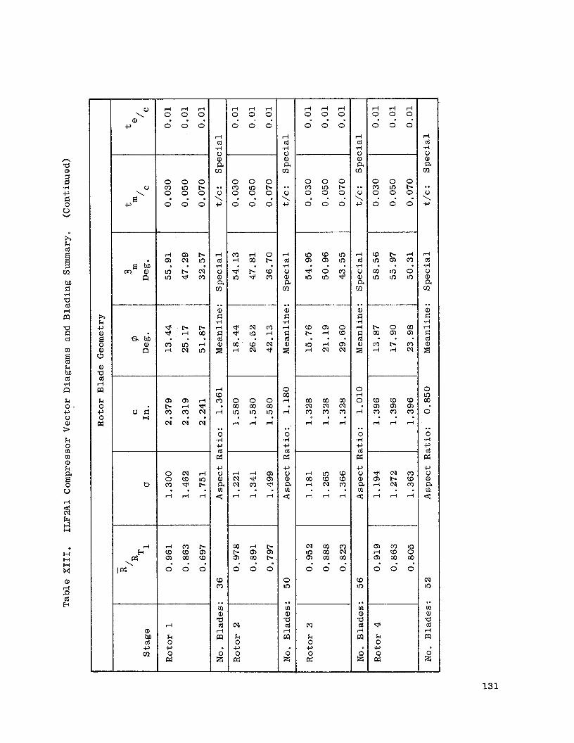
r l r l r l 0 0 0
0 0 0 . . . 0
\ a,
c,
r l r l r l 0 0 0
r l r l r l 0 0 0
0 0 0 . . .
r l r l r l 0 0 0
0 0 0 . . . e . .
0 0 0
rl cd .rl 0 a, a cn .. 0 \ c,
rl cd .rl 0 a, a cn .. a, d .rl rl d cd a, z
0 W rl
rl
.. 0 .rl c, cd cr: c, V a, a rn 4
0 ln
.. rn a, a cd rl m
g I
rl Ld .rl 0 a, a cn .. 0 \ c,
rl cd *rl 0 a, a cn .. a, d .rl rl d cd a, z2
0 In W
0
.. 0 *rl c, cd pz c, 0 a, a rn 4
cv 10
e.
rn a, a cd rl m
-
rl cd 4 V a, a cn .. V \ c,
rl cd .rl 0 a, a cn .. a, d .rl rl E: cd a, z
0 rl 0
rl
.. 0 .rl c, cd cr: c, 0 a, a rn <
CD ln
.. [rl a, a cd rl m
i
n a a, 3 r: .rl c,
u v
h k
Zi 3 cn M d .rl a cd rl m W d cd
rn
k bI! Ld .rl El k 0 c, 0 a, =. k 0 rn rn a, k a
u
2
2 Er El
H H H x a,
cd E
2
0 0 0 M l n b 0 0 0
0 0 0 M l n b 0 0 0
0 0 0 M o b 0 0 0
0 0 0 . . .
0 0 0 M l n b 0 0 0
0 0 0 . . . . . .
0 0 0 . . .
0 0 0
M W l n a a l n * O M o m * . . .
I n E El
. . . W L n O L o l n L n
h k c, a,
a, E3 a,
cd rl
k 0 c, 0
pz
m
-
* N M * l n d . . . C D a o
b r l c o 1 . .
b o w w a a . . . 8 M
a, El
V d H
M P - M d r l N
a a r l P - d * M M N
N c v c v . . .
0 0 0 w w w l n l n l n
r l r l r l . . .
W W W N N N M M M e . .
r l r l r l
W N M a P - m d c v M
O c v d O C D l n
b . . . d r l d
. . . r l d r l
w d b b a a a w t - 0 0 0 . . .
c v w o U 3 W N a w w 0 0 0 . . .
a m t o r l Q 0 a w w 0 0 0 . . .
rl E
pz
I pz'
cv k 0 c, 0 cr:
M
k 0 c, 0 pz
* k 0 c, 0 cr:
rl
k 0 c, 0 cr:
a, hD cd c, cn
131

n .a a, a 1 rl 0
c) 8
W
k
tii m M F: .rl
4 rl a a F: cd m
k M cd .rl !a k 0 c, 0 a, > k 0 m m a, k
0 u 2
i Fr el
* I--I H P( x a, rl P cd E
132
R k c, a,
0" a, a cd rl es k 0 +, cd c, m
0 \
a, c,
8 M a, !a
V E l H
b
a, M cd c, m
m a, .ri k a, m m CD
0 0 0 b c o I n . - 0 0 0 0 . . e \
o o o c ,
0 k 4
* --~ 0 0 0 (9 .. m
a, N
k rl 0 a c,
3
cd c, m
r l r l r l 0 0 0
0 0 0 . . .
0 0 0 b C D m 0 0 0
0 0 0 . . .
N N N m m m r l r l r l
r l r l r l e . .
o m m r - m m
r l d d
@ a m * . . .
b W W
m w w 0 0 0
m r - r l . . .
m k 0 c, cd c, m
m a, 4 k a, m m CD
.. s 0 k 4 , k cd rl
k .rl u
5
.. a, F: .rl rl I: cd Q, 3
m 0
rl
.. 0 Ti
c, cd p: c, 0 a, a m 4
CD CD
.. m a, a cd rl a 0 2 -
r l l - i r l 0 0 0
0 0 0 . . .
0 0 0 b Q C D 0 0 0 . . . 0 0 0
. . . m m e u C D m C D
. . . 0 0 0
* k 0 c, cd c, 111
-
m a, .VI
k a, m m (0
.. V \ c,
V k 5 k cd rl 2 0 k 4 0
.. a, El .rl rl
3 8
m W
0
.. 0 *rl $3 cd pc; c, 0 a, a m 4
CD CD
.. m a, a cd rl
d z -
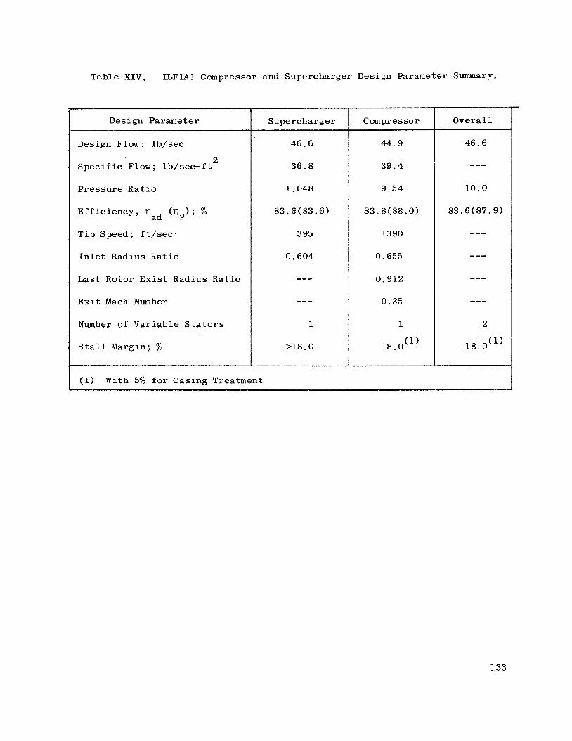
Table XIV. ILFlAl Compressor and Supercharger Design Parameter Summary.
Design Parameter
Design Flow; lb / sec
S p e c i f i c Flow; lb / sec - f t
P re s su re R a t i o
2
E f f i c i e n c y , Tad (rip); %
Tip Speed; f t / s e c
I n l e t Radius R a t i o
L a s t Rotor E x i s t Radius Ra t io
E x i t Mach Number
Number of Var i ab le S t a t o r s
S t a l l Margin; %
Supercharger
46.6
36.8
1.048
83.6 ( 83.6)
395
0.604
---
---
1
>18.0
(1) With 5% f o r Casing Treatment
Compressor
44.9
39.4
9.54
83.8(88.0)
1390
0.655
0.912
0.35
1
18.0 (1)
Overa l l
133

Table XV. ILF2A1 Compressor and Supercharger Design Parameter Summary.
Design Parameter
Design Flow; lb / sec
S p e c i f i c Flow; lb / sec - f t
P re s su re Ra t io
a
Eff i c i ency Y qad (q& %
Tip Speed; f t / s e c
I n l e t Radius Ra t io
L a s t Rotor Radius Ra t io
E x i t Mach Number
Number of Var i ab le S t a t o r s
S t a l l Margin, '%
Fan
56.6
38,5
1.048
83.6(83.6)
372
0.626
--- ---
1
>18.0
Compressor
55.1
40.1
5.68
84.6(88.1)
1410
0.663
0.879
0.35
1
(1) 18.0
Overa l l
(1) With 5% f o r Casing Treatment
134

Table XVI, ILF2A1 Compressor and ILF2A2 Supercharger Design Parameter Summary.
Design Parameter
Design Flow; lb / sec
S p e c i f i c Flow; lb / sec - f t
Pressure Rat i o
Ef f i c i ency , q ( q p ) ; '%
T i p Speed; f t / s e c
In l e t Radius Ra t io
Last Rotor Radius Rat io
E x i t Mach Number
Number of Var iab le S t a t o r s
S t a l l Margin; %
2
ad
Supercharger
56.6
38.5
1 029
83.6(83 6)
300
0.626
--- ---
1
>18.0
(1) Compressor
55.1
40.6
6.80
84.0(87.6)
1437
0 e 663
0.879
0.35
1
18.0 (2)
Overa l l
56.6
---
7.0
83.9(87.5)
2
(2) 18.0
(1) Rematched t o y i e l d o v e r a l l p/p = 7.0 a t 56.6 lb / sec flow i n t o t h e supercharger . Resul tan t compressor speed i s 101.9%.
(2) With 5% f o r Casing Treatment.
135

Table XVII, E f f e c t of Casing Treatment on S t a l l Margin.
Stage
Task I
Task I1
%
100 90 70
100 90 70
SM") f o r SM'l) w i th s o l i d cas ing
cas ing t rea tment (2)
% %
21.3 20.8 29.3
17.8 16.2 26.9
27.8 23.8 32.6
26.0 30.5 38.4
ASM
%
6.5 3.0 3.3
8.2 14.3 11.5
(1) Constant Speed S t a l l Margin.
(2) C i rcumfe ren t i a l Deep Groove Conf igura t ion .
136
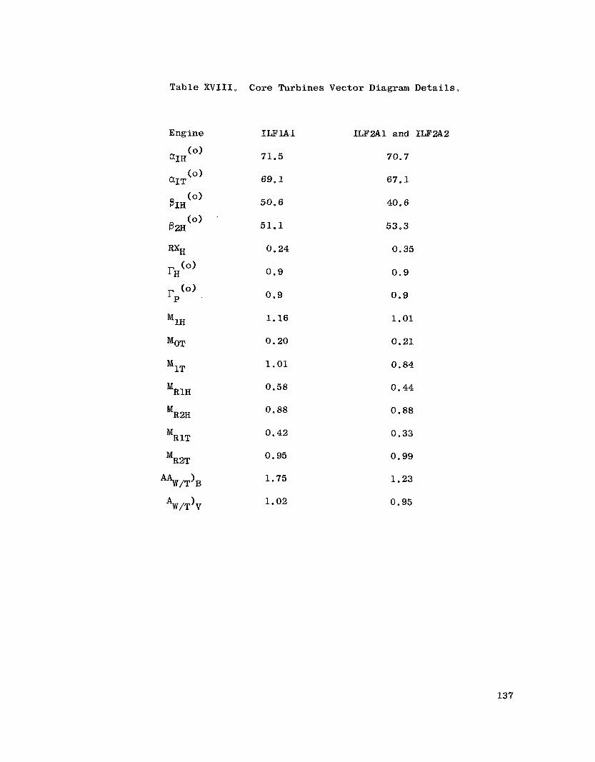
Table XVIII. Core Turbines Vector Diagram Deta i l s .
Engine
'OT
'1T
'RlH
'RW
' R ~ T
*PtV/T)B
MR2T
*W/T)V
ILFlAl
71.5
69.1
50.6
51.1
0.24
0.9
0.9
1.16
0.20
1 .01
0.58
0 .88
0 . 4 2
0.95
1.75
1.02
ILF2A1 and ILF2A2
70.7
67.1
40.6
53.3
0.35
0.9
0.9
1.01
0.21
0.84
0.44
0.88
0 .33
0.99
1.23
0.95
137

Table XIX. 'Fan Drive Turbine Blading Summary.
ILFlAl
S tage
No. Nozzles
No. Blades
Rotor P i t c h Axial Width ( i n ) .
ILF2A1
Stage
G J h/ 2Up
No. Nozzles
2
No. Blades
Rotor P i t c h Axial Width (.in.)
ILF2A2
Stage
No. Nozzles
No. Blades
Rotor P i t c h Axial Width ( . in*)
1
122
118
1.0
1
2*1&
14 6
142
0.85
1
14 8
144
0.90
2
142
15 0
0.91
2
112
120
1 .0
2
2.13
13 4
136
0.90
3
140
148
0.93
3
122
124
0.9
3
1.86
140
142
0.85
4
158
15 6
0.79
138

Table XX. ILFlAl Fan D r i v e Turbine Vector Diagram D e t a i 1 s
1 Stage N o .
56.8
52.1
54.8
58.4
0.10
53.1
49.8
1.07
0.56
0.93
0.83
0.95
0.67
0.89
1.64
1.49
2
62.6
56.1
58.4
59.1
0.10
53.8
48.9
1.08
0.66
0.87
0.90
0.96
0.64
0.87
1.64
1.75
3
60.6
50.6
55.6
55.6
0.10
45.9
38.8
0.87
0.63
0.66
0.71
0.75
0.46
0.70
1.58
2.12
139
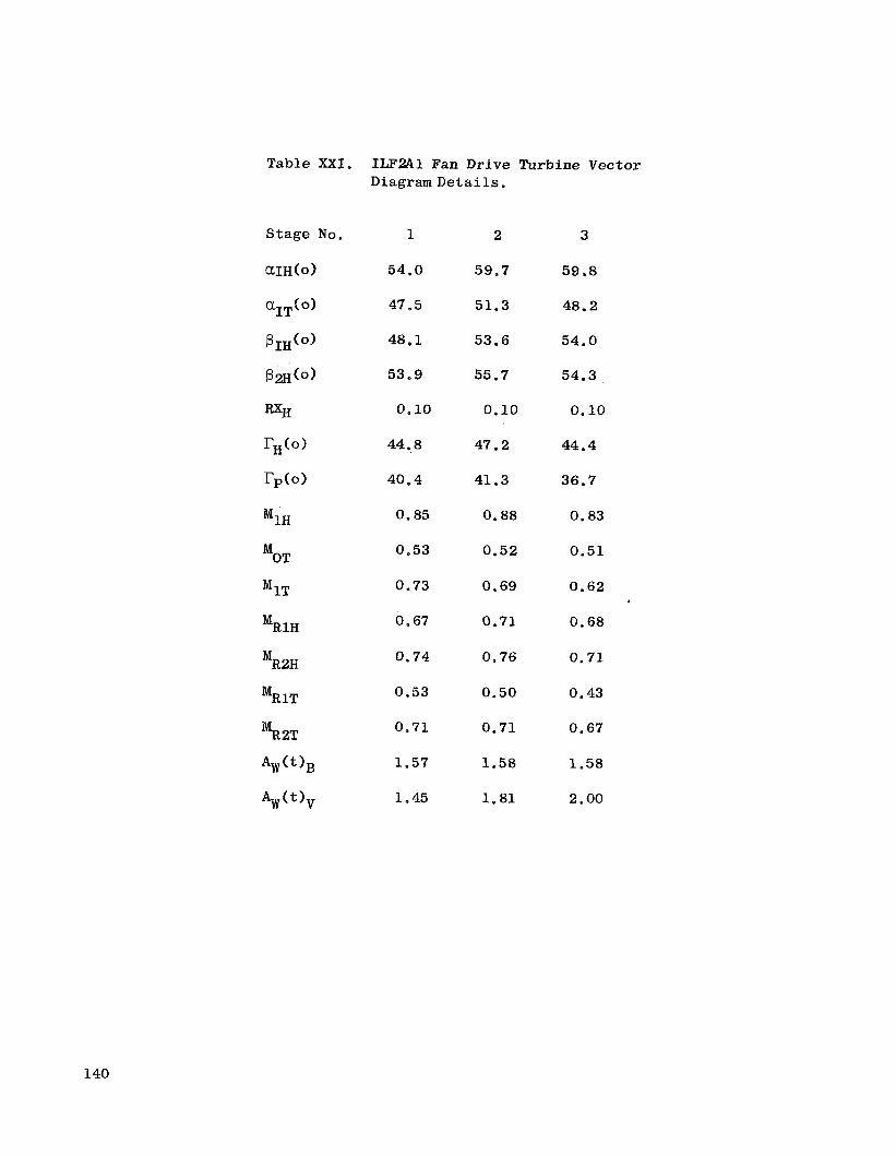
Table X X I . ILF2A1 Fan Drive Turbine Vector D i a g r a m D e t a i l s .
1 Stage No.
54.0
47.5
48.1
53.9
0.10
44.8
40.4
0.85
0.53
0.73
0.67
0.74
0.53
0.71
1,57
1.45
2
59.7
51.3
53.6
55.7
0.10
47.2
41.3
0.88
0.52
0.69
0.71
0.76
0.50
0.71
1.58
1.81
3
59.8
48.2
54.0
54.3
0.10
44.4
36.7
0.83
0.51
0.62
0.68
0.71
0.43
0.67
1.58
2.00
140

Table XXII. ILF2A2 Fan D r i v e Turbine Vector Diagram Details.
1
52.4
46.2
48.5
53.7
0.10
47.2
43.2
0.82
0.52
0.72
0.67
0.75
0.54
0.70
1.67
1.41
2
57.4
49.8
51.9
53.5
0.10
45.8
41.1
0.82
0.54
0.67
0.68
0.73
0.52
0.68
1.74
2.33
3
57.9
48.8
53.2
53.2
0.10
47.3
41.2
0.86
0.53
0.68
0.74
0.77
0.53
0.70
1.77
2.27
4
54.2
41.9
48.4
49.2
0.10
40.1
32.7
0.72
0.54
0.56
0.61
0.64
0.43
0.60
1.66
2.57
141

Table XXIII. HP Turbine Cooling Design Integral Lift Fan Engines.
T4 cycle'TS design (including margin)
Vane : Design Gas Temperature
Bulk Metal Temperature
Cooling Effectiveness & Type
Cooling Flow
Blade: Design Gas Temperature
Bulk Metal Temperature
Cooling Effectiveness & Type
Cooling Flow
ILFlAl
2500' F/2634' F
3087' F
1850' F
0.52-Convection & Film
33% Thru Flow and 4% Film
2.195' F
1610' F
0.50-Film/ Convection Holes
3.1%
ILF2A1 and ILF2A2
2000' F/2110° F
2434' F
1700' F
0.40-Convection
38% Thru Flow and 1% T.E.
1977' F
1610' F
0.27-Convection
1.1%
142

Table XXIV. LP Turbine Cooling Design I n t e g r a l L i f t Fan Engine.
ILFlAl ILJ?2A1& ILF2A2
Stage 1 Stage 2 Stage 1
Vane :
Design Gas Temperature 2366' F 2101' F 1944' F
Bulk Metal Temperature 1900' F 1900' F 1900' F
Cooling Effec t iveness & Type 0.29-Conv. 0.15 Conv. 0.04-Convection
Cooling Flow 3.95%(*) 1.0% 1.3% (Seal Blockage)
Blade :
Design G a s Temperature 2120' F Cooling Cooling
Bulk Metal Temperature 1900' F Not Not
Cooling Effec t iveness & Type 0.18-Conv. Required Required
Cooling Flow 1.25%
(*) Includes LP Blade Coolant.
143
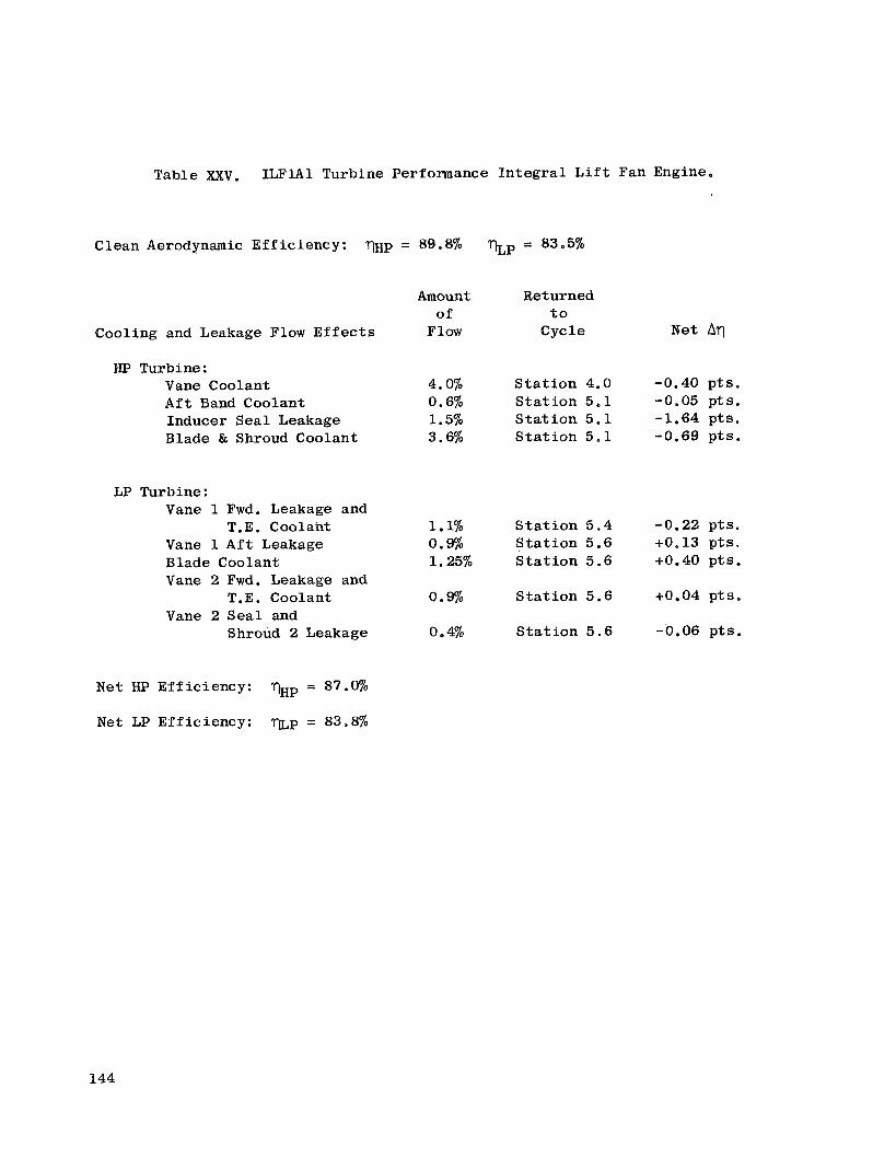
Table ~ X V . ILFlAl Turbine Performance In t eg ra l L i f t
Clean Aerodynamic Eff ic iency: q ~ p = 89.8%
Cooling and Leakage Flow E f f e c t s
HP Turbine: Vane Coolant Aft Band Coolant Inducer Sea l Leakage Blade & Shroud Coolant
LP Turbine: Vane 1 Fwd. Leakage and
Vane 1 Aft Leakage Blade Coolant Vane 2 Fwd. Leakage and
Vane 2 Sea l and
T.E. Coolant
T.E. Coolant
Shroud 2 Leakage
N e t HP Eff ic iency: qHp = 87.0%
N e t LP Eff ic iency: q ~ p = 83.8%
Amount of
Flow
4.0% 0.6% 1.5% 3.6%
1.1% 0.9% 1.25%
0.9%
0.4%
xp = 83*5%
Returned t o
C y c l e
S t a t i o n 4.0 S t a t i o n 5.1 S t a t i o n 5.1 S t a t i o n 5.1
S t a t i o n 5.4 S t a t i o n 5.6 S t a t i o n 5.6
S t a t i o n 5.6
S t a t i o n 5.6
Fan Engine.
N e t Aq
-0.22 pts . +0,13 pts . +0.40 p ts .
+0.04 p t s .
-0.06 p t s .
144

Table XXVI. ILF2A1 and ILF2.42 Turbine Performance In t eg ra l L i f t Fan Engine.
Clean Aerodynamic Eff ic iency: %p = 90.0% xp = 86.6%
Amount Returned of t o
Cooling and Leakage Flow E f f e c t s Flow C yc le N e t Aq
HP Turbine: Vane Coolant 1.0% S t a t i o n 4.0 -0.10 p t s . Inducer Sea l Leakage 1.1% S t a t i o n 5 .1 -1.22 p t s . Blade & Shroud Coolant 1.3% S t a t i o n 5.1 -0.06 p ts .
LP Turbine: Vane 1 Fwd. Leakage 0.1% S t a t i o n 5.4 -0.02 p ts . Vane 1 Aft . Leakage 0.6% S t a t i o n 5 . 6 +0,12 p ts . S tages 1 & 2,Shroud Leakage 0.3% S t a t i o n 5.6 -0.10 pts .
N e t HP Eff ic iency: m p = 88.6%
Net LP Eff ic iency: xp = 86.6%
145
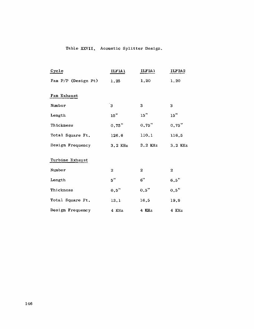
C v e l e
Table XXVII Acoustic S p l i t t e r Design,
Fan P/P (Design Pt)
Fan Exhaust
Number
Length
Thickness
T o t a l Square F t .
Design Frequency
Turbine Exhaust
ILFlAl
1.25
3
15"
0.75"
126.6
3.2 KHz
ILF2A1 ILF2A2
1.20 1.20
3 3
15" 15"
0.75" 0.75"
110.1 116.5
3.2 KHz 3.2 KHz
Number
Length
Thickness
T o t a l Square F t .
Design Frequency
2
5 I t
0.5"
13.1
4 KHz
2
6"
0.5"
16.5
4 K H Z
2
6.5"
0.5"
19.9
4 KHz
146

Table XXVIII. Noise Constituents.
Noise Rating Point (10000 lb) PNdB, 500 ft. Sideline
12 Engines
Engine
Fan P/P (design pt.)
Fan Unsuppressed
Fan Suppressed
Fan Jet
Core Jet
Total Jet
Turbine Unsuppressed
Turbine Suppressed
Total Jet plus Turbine
Total System
Objective
90° F Day
ILF2A2 ILFlAl ILF2A1
1.25 1.20 1.20
115.6 114.1 116.7
93.9 93.7 91 .8
85 78.9 78.9
85 .8 82 .4 82 .4
88.7 84.2 84.2
96.4 96.3 97.6
83.8 83.7 85 .O
90.2 87 .8 88.3
96.1* 95.3 94.5
98 95 95
* Could be reduced to 95 PNdb with additional treatment (As" splitter length).
147

a, c TI M El w
a a, k cd a,
148

149

0 0 co rl
d 1 a a, a, a rn a .?-I
a a, c, 0 a, k
O k 0 0 m u rl
CI (d Fr
0 0 0 rl
h
k 0 w
a, Q
.rl c, (d rl a, p:
M
0 Q,
0
0 00
0

u a, VJ \
t;:
‘0 cv
rl
X
l5 sk .. a a, a, a 02
a .rl E -5 a, 9 0 a, k k 0 u
16
15
14
13
12
11
10
9
8
7 1.2 1 . 3 1 . 4
Fan P res su re R a t i o , P/P
1.5
Figure 4. I n t e g r a l L i f t Fan Study Task I Se lec t ed Re la t ion Between Fan P/P and T i p Speed.
151

M
rl
a II 0)
=-"
rl = d/d u=a
I I I I I I N 0 rl rl
Y 0 W W
N rl rl rl
ld c, (d CI 0 .rl k c, a, E cd k (d
H
% cd H
152

c) *I4 k c, a,
k cd PI
El
H
i! cd E h 0
.d 4J '0 of 5 EZ c,
m a, E: *rl M E: w
In In td a R m
153

m rl
II
PI PI a, rl 0 A 0
- \-
- A?
m II
PI - \
PI a, rl 0 A u
In 0 m
K- 0 0 o m
c u m c u r l
154

Er 0
F"
0 0 In
0 In d
4
155

0 0 v3
0 In In
0 0 In
R 0
0 In d(
0 0 0 0 - m u )
0 0 d(
l-i 0 In M
14 \ 14 fi ld R
156

id k 1 bD .rl w c 0 u
n
rn
.rl rn I: a, E .rl n I
rn a, k 5 W a, 0 0 k PI bo I: .rl N .PI m
0 rl
157

m -!a
c, cd k 5 M .I4 w
u 8 a a, k cd
8 n
.. a, k 5 a a, 0 0
&
158
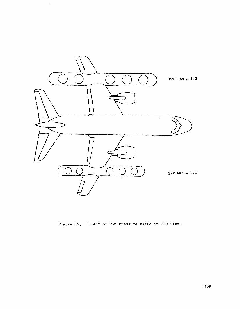
P/P Fan = 1.4
Figure 12. Effect of Fan Pressure Rat io on POD S ize .
159
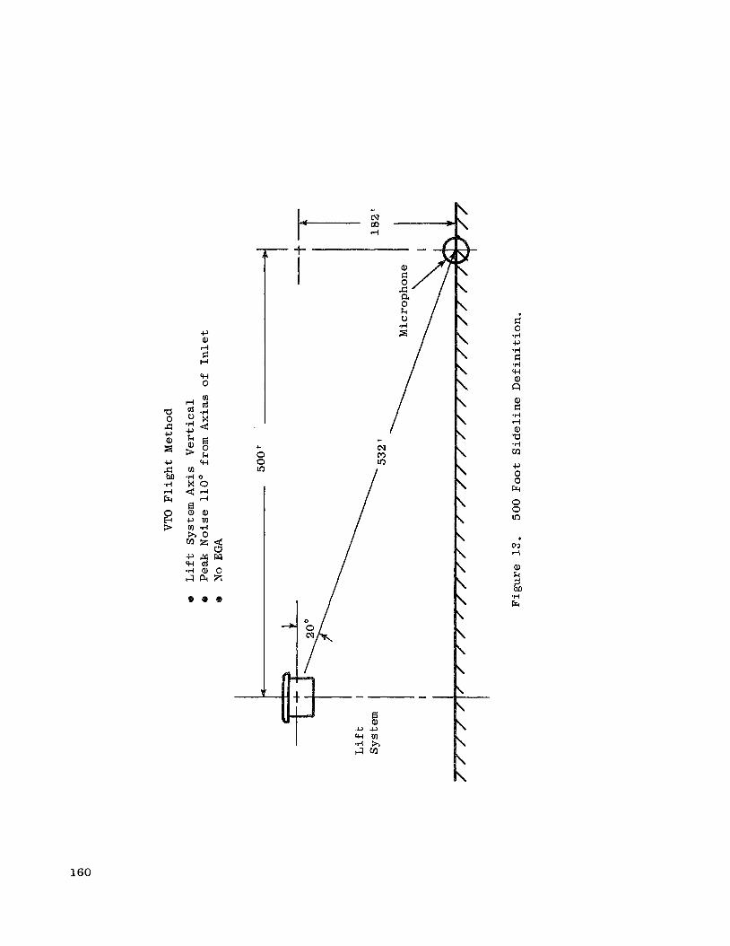
c, (0 d E: H
w 0
e a ) .
160

4 \ X
0 0 M
0 cv
LD
In
d
M
cu
l-i
0 0 0 d

0 Radiated
5 # - e a
10 d @I a
Inlet Max. Noise
Exhaust
e Exhaust Noise Suppressed to Equal Inlet Noise Before Inlet
e Inlet Radiated Noise 10 db Below Exhaust Radiated Noise
Suppression Required
e Inlet Suppression = Fan Suppression, 7 PNdB
e A s Source Noise is Reduce,!, Inlet Suppression Requirements
e APNdB Inlet = APNdB Exhaust - 7 PNdl3 - APNdB Source Reduced to Maintain Constant Total Noise
Figure 15. Inlet Suppression Requirements.
162

0 0 i-l
I
d cd Er
0 M
0 N
0 4
0
m a k .. d 0 TI m m a, k a a 5 cn
9 Er
5 a, m m a, k a a d 5 2
a, m .I+ 0 2 d cd c, 0 E d 0
G 0
.I+ m v1 a, k a a 5 m d cd
Er w 0
c, 0 a, w w w
v) d
a, k 5 bo .I+ Er
163

0 0 cu rl rl rl
0 0 to b
BPNd
rl \ 0 b m rl
c, rn
rl rl
0 .rl c, cd E a, k
rn a, k PI
2
rl
El M
0 w 0 rl \ 0 In to II
s s* 73 a, a, a m a TI B
164

0 nl rl
Fr
0 0 u) nl
I I
0
F;" 0
0 rl
II
PI \ PI a, k 0 u e
d(
rl
II
PI \ PI C cd Fr
a, C .rl rl a, a .I4 m c, Er 0 0 v)
e
n se 0 0 rl v
c,
k s E (II P Cll 0 0 0
0 rl
Q
$
..
0 rl rl
0 0 rl
UJ
\ =-" s? I
0 .I4 c, cd !x C 0 .rl c, V cd k c, X w
a, (II *I4 0 a c, a, 5
d 0
0 .rl c, cd fr: C 0 .rl c, V cd k c, x w a, rl 0 h u w 0 c, u a, w w w
00 rl
a, k 5 M 4 Fr
0 00
8PNd
165

m .r: 3
+ m u +" B
I1
a, rn .rl 0 z a, b
0
c,
0 a, rn \ c, Fr W W I?
II
m 9
4
rl
0 cu rl
0 4 rl
0 0 rl
8PNd
0 Q,
0 0 00 63
0 0 W N
0 0 d( N
0 0 cu N
0 0 0 cu
0 0 00 I-l
a, m .rl 0 2
E: 0 d B a,
h O U
- w $ 0
c, 0 al +I w w
166

0 rl rl
r )
rl
II
(D
=-" 9 \
e
0 rl
I1
PI \ PI a, k 0 u
10 0 rl
% Er
0 00
:
0 0 rl
0 Q,
u) 00
0 0
In 01
0 01
10 d
0 rl
In
3
m a E n
T I m 0 a, k a m FI cd Fr
9
P a, m v1 a, k a a 5 m c; 5
a, m .rl 0 R
% m m a, k a a cf m rj 0 c, rn 1
2 w 0 c, L, a, w +I w
0 co a,
ba
Er
s .rl
8PNd
167

0 rl rl
a, c: .rl rl a, a .d m u
c, rn El k
E c ha .rl m a" se. 0 0 rl
e
In 0 rl
cv
I - 7
0 0 rl
In Q,
0 Q,
0 M
In cv
0 co
In rl
0 rl
In
0
m d z 2l
8 n
.d m m a, k a a I VI c: cd Fr
a a, m m a, k a a z s
a, m .d
2 c 0
0 .rl c, cd CZ a, k El m m a, k PI w 0 c, 0 a, w w w
rl cv a,
!i .rl Frc
8PNd
168

0 rl rl
4J m 5
a , k C S
F r m
M cn
a a, k cd
$
0 M
M cu
0 hl
3 E .. I: 0 .rl
m m r l m
a, k a a 1 M
C cd Fr
0 l-i
a a, m [I] .- a,
Lo a ca D E
s
a, m .d
a a, m m a, k a a 5 v1
a a, k cd a, c3 a 3 a a, k cd a, r3
0 2 w 0 d 0 m *d k cd a
u
::
8
cu hl
a, k 1 M .d Fr
169
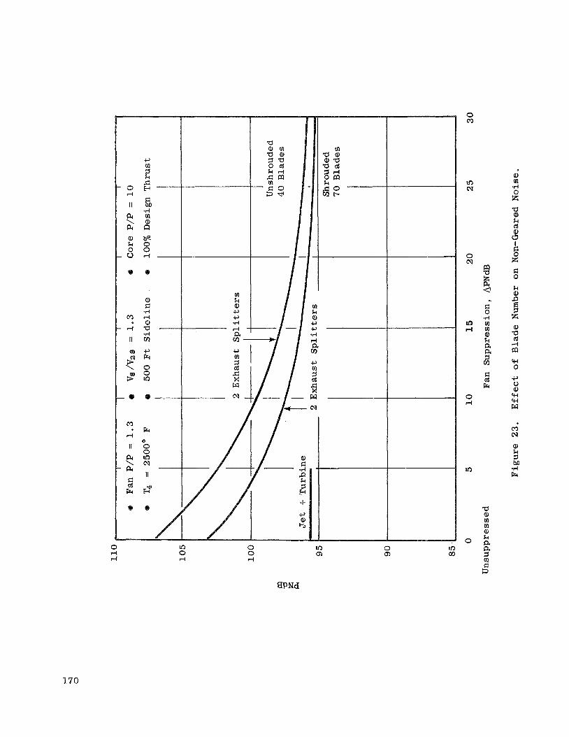
0 rl
II
PI \ PI a, k 0 u
M
rl
II
u)
\ 9 5
- 0
M
rf
I I
pc \ PI I: cd Erc
.I4 rn a, n
a, I: .I4 rf a, a - .I4 v1
c, Erc 0 0 In
e-
Er
0 0 In cv II
0
€?
In 0 rl
m k a, c, c, .I4
0 0 rf
In cn 0 cn In co
0 M
In cv
0 cv
u9 rl
0 rf
In
0
% E a -. I: 0 .I4 m m a, k a a 5 v1
E: cd Erc
a a, m m a, k a a 2 s
a, III .d 0 x a, k (d
$ k
3
x
k a,
x a, a cd
I 4
rn w 0 c, 0 a, w w Fil
m cv a, k
.I4 Er
8PNd
170

m k a, +., +., .rl rl a m cr)
0 0 ri
0 cn
8P Nd
a a, rn rn a, k a a 5 ul
B Fr
a a, a 5 0 k
F: 3 5
i a, k 5 hQ .rl Fr
171

G td R
0
rl
0 0 0 0 0 rl 0 m M b rl ?I
a a a 5 0 k
F 3 a a, k cd
9
$ :: 0 z
In N
8PNd
172

W
0
Fuel Used i n Lilt, I,b
0 0 0 d
i Lo 1 0 0
u Fr rn F: 0 0 .d -I-’ ld lz a, k 5 [I) [I)
k PI
0 a, .rl c, cd cr: a, k
[I) [I) a, k
9 Fr
0
c, 0
y-l
w
5 y-l
PI a, F: +I cd Er
W c\1
a, k 5 hl) .d Fr
17 3

% R
a, rl P (d k 0 r m oa, a , G k- .r(
BD O G o w 0 - a , N m
.d
N U ” E
m a, c -4 M c W r w .A GI 0 0 0 0 rl
x 0 r-i
0 a 0 14 a, G N .rl 0
w o m I1
3 9
‘ 8 N U
0 rl rl
n !2 \ Gl
In N 0 0
v
0
-F
/ B = : e m o +
M
rl
II
m
\
-
=-N $ Q -
R 0 0 0 m frl
-
0 rl
II
14 \ 1 4 - a, k 0 u e
iz 0 0 m
e
w R 0 0 0
0 N
e
m c- 0
II
z 0
0 (D
0 03
0 0 W I?
d s R a, m .rl 5 k u a E: 0
0 .I4 c, Ld G a, k 5 m m 0 k PI rs cd R w 0
c, 0 a, w w K!
b hJ
a, k 5 bD .rl R
174

Fan Radius Ratio
II) In w 0 0 0
0 CD
k a,
a, k s m rn a, k P,
d cd Fr
03 cu a, k s M
175

0 0 l-
- Yl
0 rl
II
a, k 0 u PI \ PI
Fr
0 0 In cu II
0
s
M
r l .
I I
m 9 9 \
0 0 co
0 0 v)
0 0
0 0 €9
176

a a, a, a ul a .rl E-r a, c, cd k a, d s
0 rf
I I
pc \ PI a, k 0 u
M
rf
II
m
\ 9 9
Er
0 0 v) tu
I I
0
$
a, - k
rn a, k PI
2 -
0 0 0 rl
0 0 OT)
0 0 CD
0 0 d
v)
rl
d rl
0 .rl c, (d rr; a, k
[II a, k PI FI (d k
2
177

0 0 0 0 0 cx)
0 0 v,
0 0 0 0 d( co

0 E r m d
a a, a, a rn a .rl E a, c, (d k a, a 2 e
0 0 0 01
0 0 co d
0 0 01 rl
cv M
179

Fr
0 0 In N
I I
0
9
I 0 i-l
II
P.i \ PI a, k 0 u
I
m rl
0 0 r. i-l
0 0 co i-l
0 0 10 4
0 0 d( P I
0 0 m i-l
0 0 N i-l
0 0 i-l i-l
0 0 0 i-l
t sw .. a a, a, a m a b FI cd k
.I4
a a, a, a m a
Yl h I: cd Fr w 0
c, u a, +! w w
m m a, k s M
Fr .A
180
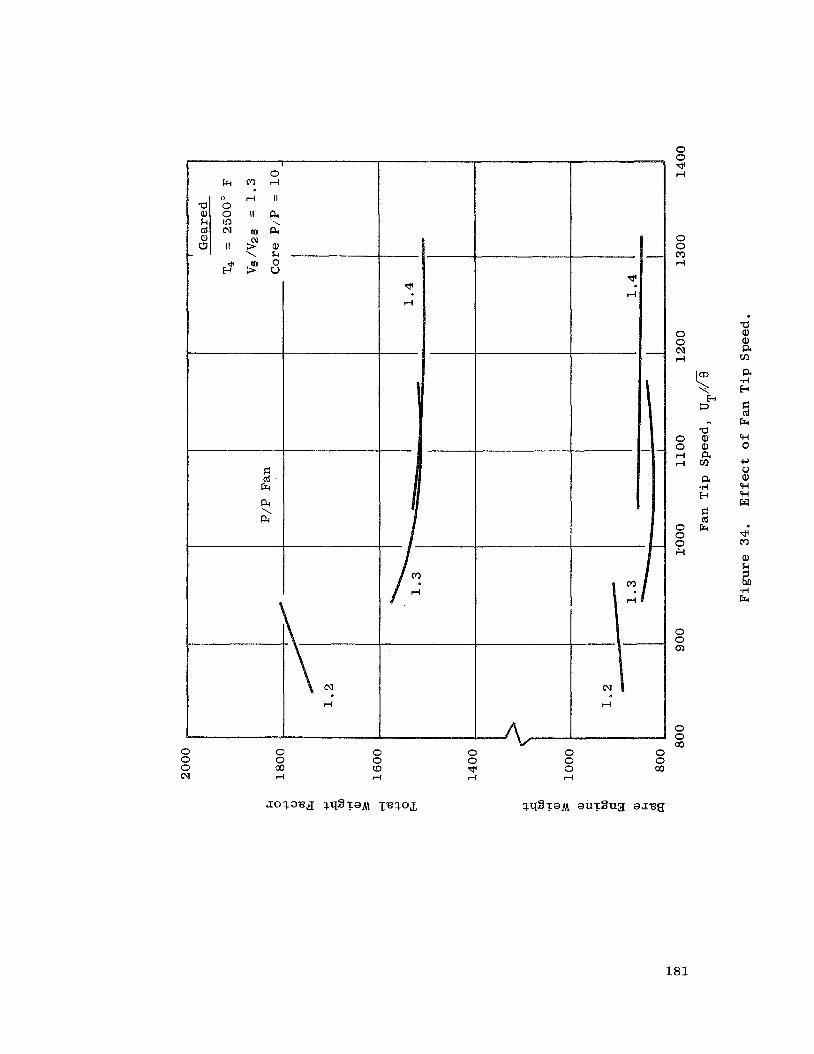
M
rl
0 0 0 rl
0 0 00 rl
0 0 co rl
0 0 d( 4
d
I-
0 0 -3 rl
0 0 03 4
0 0 N ri
$ E
3
a o a , o a , r l a r i m
a .A E G cd
O F r 0 0 ;I
..
0 0 Q,
0 0 00
0 0 00
181

0 0
rl m
P
al P rn
. a l c, a al .a 0 s
0 0 (9 4
0 0 v rl
0 0 N
0 0 0 rl
0 cu m rl
0 t-
'rl rl
0 (9
' 0 ,
In (9 .rl rl
8 In 0 rl
m
0 In m
In 0 0 rl
In x
a a, 0, a v1
a .rl E.r a $2 cd 0 .rl c, cd p: a, k 5 m m a, k !a I: cd Er w 0 c, u a, w w El
v) r)
a, k 5 bD .rl Er
rl
182

a a, a, a v)
6 . I4 3:
a a, a, a v)
a, c, (d k a, P
2
0 0 d rl
0 0 hl rl
0 0 0 rl
0 0 Q)
0 0 W rl
In I? hl rl
a a, a, a m a .r( r3 P I: (d
a, k 5 v) v) a, k PI
3 Fr w 0 42 0 a, w w w
co 0 a,
183
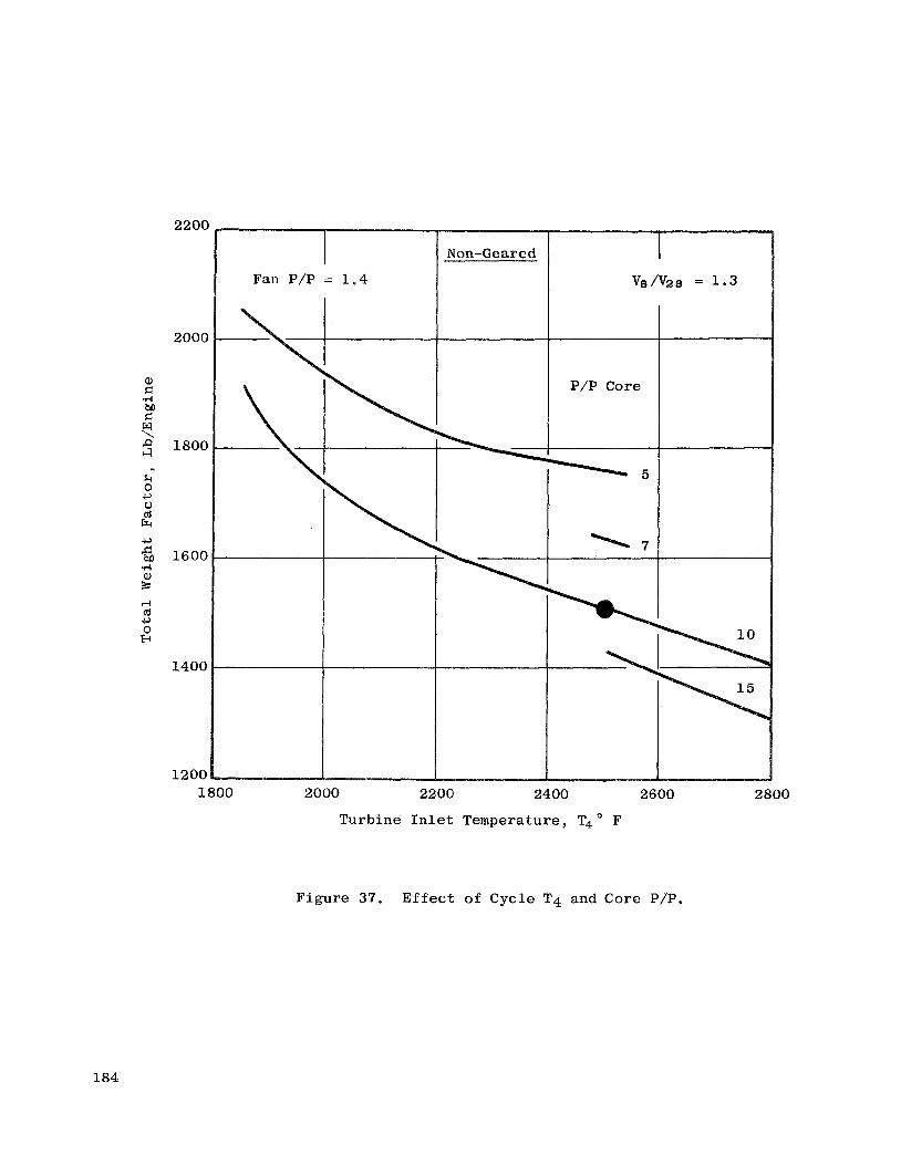
2200
2000
1800
1600
1400
1200
Non -Ge are d
Fan P/P = 1 .4
1800 2000 2200 2400 2600 2800
Turbine I n l e t Temperature, T40 F
Figure 37. E f f e c t of C y c l e T4 and Core PIP.
184

2000
1800
1600
1400
1200 1800 2000 2200 2400 2600 2800
Turbine I n l e t Temperature, T4 F
F igure 38. E f f e c t of C y c l e T4 and Core P/P.
185
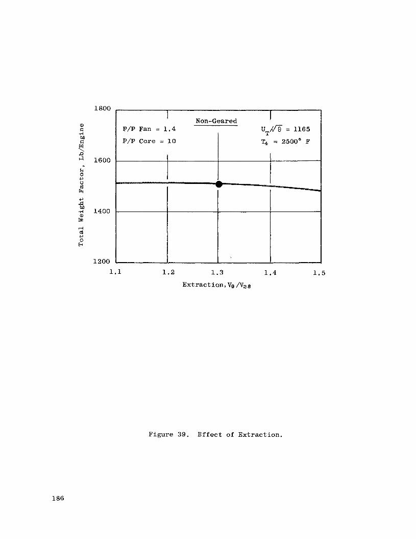
1800
2600
1400
1200
Non-Geared P/P Fan = 1.4 UT/a = 1165
P/P Core = 10 T4 = 2500° F
1.1 1.2 1.3 1.4
Ext rac t ion , Ve /Vze
1.5
Figure 39. E f f e c t of Ex t r ac t ion .
186

0 0 00 rl
d 2
H 00 9 d/ I I I
0 0 t- rl
0 0 CD rl
0 0 Lo rl
d rl
M
rl
cu r-i
0 0
2
In W rl rl
0 .rl c, (d
k P4
187

190(
180(
170C
1600
1500
I
Geared
20,000 Ft I 0.75 Mo
1400 1.2
850
1.3
Fan Pressu re Ratio
1035
UT/&
1.4
1165
Figure 41. E f f e c t of Range - VTOL Airplane .
188

1900
1800
1700
1600
1500
1400
0.8 Mo
1 . 2
850
-I__ - _ _ _ _ ____
35,000 F t 2000 N
1 .3
Fan P res su re Ra t io
1035
1 . 4
1165
Base l ine Miss ion 0.75 Mo
20,000 F t 500 NM
Figure 42. E f f e c t of A l t e r n a t e STOL Mission.
189

In
0 0 N N
0 0 0 N
0 0 00 rl
0 0 co rl
rl
rl
N I .
0 0 d l-i
0 .rl c, cd p: a, k 5 rn m a, k E4 I= cd Fr
l-i rl
m * a, k 5
0 ln CQ
190

FI 0 .rl c, cd M -rl c, m a, + E: H
H H H
I
H H
4 cd b k 0 'H
m E: 0 .rl M a, p:
0 0 l-i rl
0 0 0 rl
0 0 Q)
5 a, k cd
a , o k I cd
O B
= 9
a , %
0
0 0 co cu
0 0
cu
0 0 * sa
0 0 cv cu
0 0 0 cu
0 0 o? rl
0 0 c.0 rl
I
rn c,
0 5 rn r $ s
191

2000
1900
a, .: 1800 ho r: w \ P ;I
k 0 c, u 1700 cd R c,
6 TI a, s d cd 1600 c , - 0 f+
1500
1400
Regions for Task I1 - I11 Investigation v6 /v2 8
P/P Fan = 1.3 P/P Core = 10 Geared
0 Non-Geared I
P/P Fan = 1.2
P/P Core = 1
1600 1800 2000 2200 2400 2600 2800
4 O F
Figure 45. Weight Factor Results - Recommended.
192

0
cu I I
a +3-
a a, a, a v1
a .d E
a .d 3:
e a, a, a m a
.rl E a, c, cd k a, a 64
rn a, M cd c, rn a, G .d P k 7 H p* 4 w 0 k a,
2 x c 0
a a, a, a tn a
.rl I3 a B F .rl a cd 0 la
E d w 0 $-' t, a, w w w
co dl a, k
.d 5 G.4
193

0 0 0 d
0 B
0 0 00
0 0 t-
0 0 0 E*)
0 0 OD cv
0 0 co cu
0 0 * cv
0 0 cv cv
0 0 0 cv
0 0 OD d
0 0 t- rl
w 0
c, u a, w w w
r- d
194

rn a, M Ld +, v1
In CU
II
a S I -
0 0 b rl
0 0 cc, d
0 0 0 m
0 0 b, N
0 0 3 N
0 0 d N
0 0 N N
0 0 0 N
0 0 00 rl
0 0 cb
k 0 c, 0 Ld Fr c, s M .rl
d Ld c, 0 E
a, k 3 M TI Fr
195

E: (d h a a, m m a, k a a $ 3
0 k Q) c, c, .A d a Cn cu I
0 cu rl
0 rl rl
0 0 rl
0 Q,
d m c u d d . .
0 .A c, td p:
196

c, m 1 k c: E m P Cll 0 0 0
0 rl
-
c, E: .rl 0 a bll E: .rl -I-’ cd cr: a, rJY .rl 0 z
m a, E: .rl bJl E: W cu rl
e
0 0 0 cn rl
0 rl rl
U U c u m m m
E: 0 .rl c, 0 .rl P 3 k pc a, m .rl 0 R c, a,
C-J
3
c, 0 .rl P a, k a c, a,- 5
E: Ld w4
P a,
0 03
c, El *rl 0 04
8 .rl m a, cl
M rl
In cu rl
cu rl
c, El .I4 0 a bn E: .rl c, Ld !x a, m .rl 0 R
d cu rl
0 .rl c, cd !x a,
O k @a r l m
a, k a E:
Ai
2
W rl
rl
197

0 0 v rl
0 0 N d
0 0 rl 4
0 0 c\J m
0 0 0 m
0 0 co N
0 0 CD N
0 0 w c\1
0 0 N c;I
0 0 0 CJ
0
0 0 0 rl
198
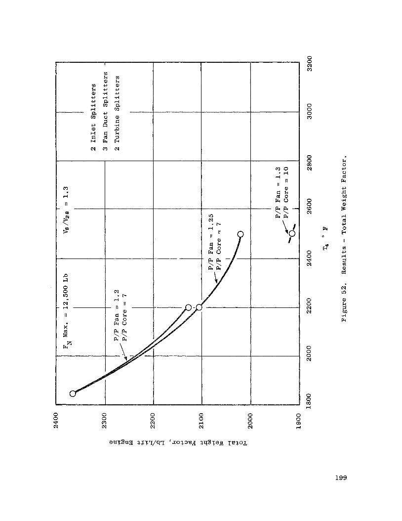
P 4 0 0 In cu i-4
II
0 0 * cu
0 0 M N
II - 1 1 -
a, G & a 0 Eru PIPI \ \ & P I
0 0 cv N
0 0 4 cv
M O 1 0 4
0 0 0 cu
0 0 cn rl
0 0 cu M
0 0 0 m
0 0 00 cu
0 0 co cu
0 0 * cu
0 0 cu cu
0 0 0 cu
0 0 00 Pi
k 0 c, 0 of
Er
a, G
199

b
It
a, k 0 u 14 \ PI
0 0 00 rl
0 0 co rl
0 0 9 l-l
0 0 0 0
0 0 00 cu
0 0 co cv
0 0 dl ea
0 0 N hl
0 0 0 cu
0 0 00 rl
0 0 co rl
Er 0
& .. a, k 7 c, ld k a, a 8 a, E c, a, r( c H
a, c .rl P k 5 w a, k 1 m m a, k a 6 2
m c, fi a,
k b % -rl
a, e: bl) d *rl r l 0 0 u -0 c cd a, k 1 + cd k a, a
E c, a, rl c H
a, d .rl P k 7 E c cd
Err F: 0
a, k 0 u PI \ PI a
8
9 dr E w 0
c, 0 a, w w w
M In
a, k 7 M .rl !a
200
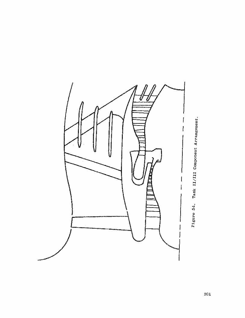
20 1

* E: .d M k of z rl rl Ed c, M
a a, a, a M
c, G of c, v1
u
19
18
17
16 Fan ILF2Al
3 . 5 4.0 4.5
Rotor Aspect Rat io , Average Blade Height/Chord
21
20
19
Fan ILFlAl 18
2 .5 3.0 3.5
Rotor Aspect Rat io , Average Blade Height/Chord
Figure 55. Fans ILFlAl. and ILF2A1 Parametric Study.
202

18% Constant Speed S t a l l Margin, without Casing Treatment
18% Constant Speed S t a l l Margin, with Casing Treatment (3% SM f o r C a s e Treatment
900
Design Aspect Ratio = 2.886
850
Speed = 855 Ft/Sec
800
750
700
800
750
700
2 . 0 3.0 4.0 Rotor Aspect R a t i o , AveraSe Blade Height/Chord
F igure 56. Fan ILF2A2 Parametr ic Study.
203

32
30
28
26
24
22
20
18 $
z z
c c H
16
d 14
12
10
8
6
4
2
0 I I I I I -6 -4 -2 0 2 4 6 8 10 12 14 16 18 20
Axial Coordinate Inches
F i g u r e 57. Fan Flow P a t h I L F U l .
2
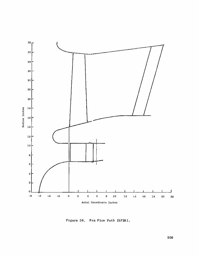
32
30
28
26
24
22
20
18 .a E: H
67 16 7 4 a
14
12
10
8
6
4
I I I I I I I I I 1 - J
-8 -6 -4 -2 0 2 4 6 8 10 12 14 16 18 20 22
Axial Coordinate Inches
2 05

32
30
28
26
24
22
20
rn 18
%
I" G
16
.?I a E 14
12
10
8
6
4
-6 -4 -2 0 2 4 6 8 10 12 14 16 18 20 22 24
Axial Coordinate Inches
Figure 59. Fan Flow Path ILF2A2.
2 06

Adiabatic Efficiency
0 cn 0
0 0 W P-
0 0 0 N rl
0 rl rl
se. 0 0 rl
0 cn
0 W
0 b
0 UJ
0 10
0 v
0 M
0 N
0 rl
0
2 v1 a, -6 n
Iv Q
$
@
w 5= \ n
N co
W
v 3w
5 rl F F: cd F a a, .i, 0 a, k k 0 u 6 4 v1 a,
w 0
c, cl a, 0 k a, PI
n
0 0 ‘;r M rl rl
0 N
rl
0 0 rl 0
rl rl
2 07

Adiabatic Efficiency
TAD 0 0 0 Q, co t-
0 (v rl
0 rl rl
* 2 0 o m
r l a , a n N
0 9
2 o w c Q \
n N a
o @ l?
W 2
8 i 5 4 Er E: (d
C E r 0
5 d c,
k O k d r o
V
8
B " $
.r( o m
w 0 c,
O E : N a ,
0 k a, PI
0 rl
0
0 0 0 0 0 dr M (v rl 0
208
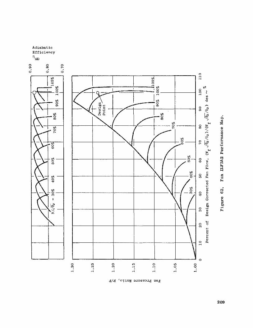
Adiabatic Efficiency
0 0
I I
0 M rl
In 0 In N N rl
rl rl rl
0 In rl 0
rl rl
0 rl rl
0 0 rl
0 cn
0 OL,
0 b
0 co
0 In
0 *
0 03
0 N
0 rl
0
0 0
rl
a 09

0 rn 0
A d i a b a t i c E f f i c i e n c y r) AD
0 co 0
co 0 d
5 a, a, a m a E c cd
Erc
. o a, m \ +-, Fr 0 W 9 rl
II
ad
W
E k 0 P QI m
I 1
\ w Fr 0 co rl rl.
II
E k 0
W d,
II
2 lR 0 0 d
I
2 Erc I4 W
a, c .d M c w
2 se 0 0 i-l
,. rl
I4 d Erc GI
a, c .I+
M c kl
W
dr 0
4
cv 0 d
0 0
d
210

Adiabatic Ef f i c i ency
%D
0 a,
n a a, 0 a M a .rl k
E: (d E W
co 0 rl
c, E
II
E a k
II
2 * 0 0 d
.. a, w 0 2
0 0 d
0 a,
0 co
0 d(
0 N
0
* .. e
zh L
a a, a, a rn fi cd Fr a a, c, 0 a, k k 0 u
d( 0
d
N 0
d
0 0
d
a, 2 z 0 y-i k a, PI a, G .d i.4 M G .I4 c, cd k a, a 0
2 3 w k a, M k (d
k a, a 5
’ f
* (0
a,
2l .I4 E
211

cv r(
231.
0 rl

m d
N d
0 d
N N 0 1

----
I- I
6-
I 1
Cladding -
- E/G
Figure 67. Epoxy/Graphite Fan.
214
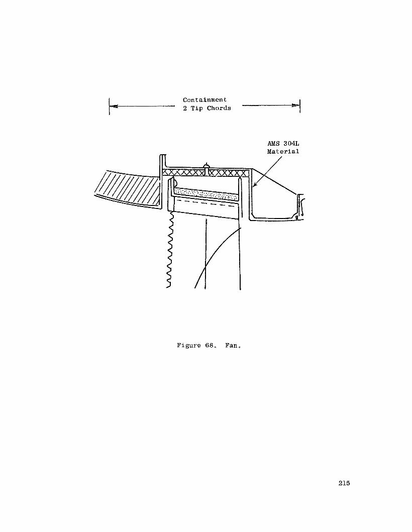
Containment 2 Tip Chords
A?vIS 304L Material
Figure 68. Fan.
215

u3
0 11
m
?ll z
0 rl
I I rn a, a
64 \ 64
rn a, M cd + m u3
I1 2
P I4
u3
+ d s e w m rl II
-0-
m cu rl 0 rl rl rl rl
0 0 0 0 0 0 0 0 0 0 0 0 0 '0 Q) W b co Lo w m rl rl rl rl rl 4 rl
0 Q) a2
rl 0 0
3a8' ' a/ a
In b
0
u3 b
0
0 b
0
n
# \
0 % c o w
E
X
0 b
0
n
\
a -
E
10 ex
d
~
0 0 0 0 0
cu rl rl cu + + I I
h .a I c, m 0 .rl k c,
k 0 rn rn Q, k a E 0 0
216
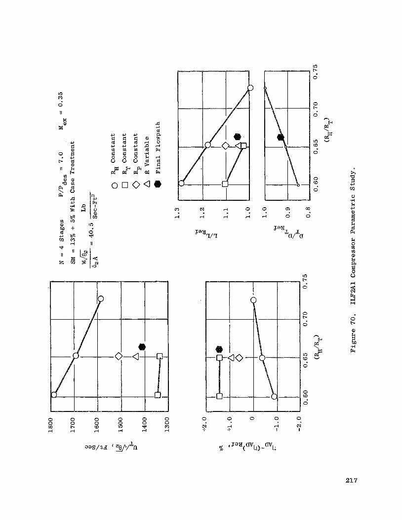
N
A rn
o o o a m SI rl 0 rl rl rl rl
0 a 00
rl 0 0
;L a/ a
0 0 0 0 0 0 0
0 0 0 0 00 E- (D 5: w M rl rl rl rl rl rl
0 0 0 0 0
SI + rl IF’ I I
In P-
0
0 P-
O
In P-
0
0 (D
0
0
0 (D
0
. . cd PI
0 b
a, k 7 bn .rl Fr

Overall Ad i a bat i c Efficiency
TAD 0 0 0 Q, Q) b
0 0 0
0 0 0 0 0 0 M rl cn b In M rl r-l
0 0 rl
. . k a, PI k 0 rn
218
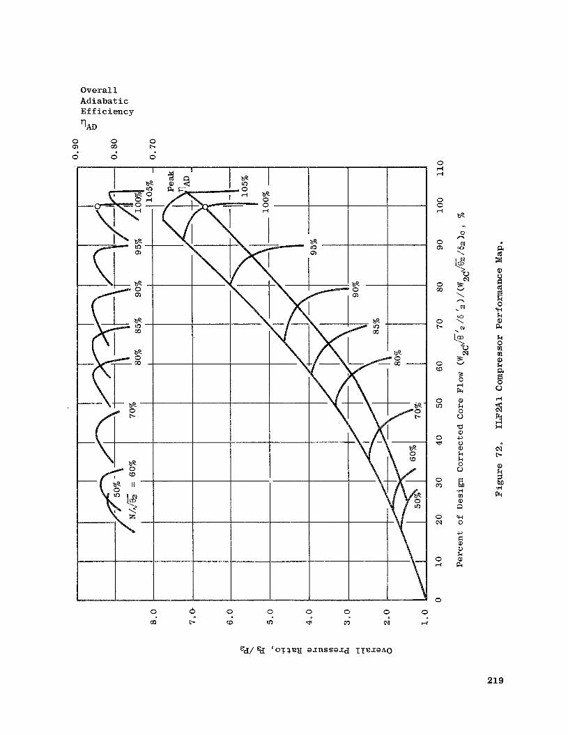
Overall Adiabatic Efficiency
TAD 0 0 0 Q) W + 0 0 0
‘ s e
0 0 0 0 0 0 0 0
m b W 0 * m N rl
0 rl 4
0 0 rl
0 0,
0 m
0 +
0 W
0 Lo
0 w
0 m
0 cu
0 4
0
se .. 0 n N a \
% W 2 \ n N
og \ 5
R1 s W
5 El a, k 0 u P a, c1 0 a, k k 0 u GI .rl (I! a,
w 0
c1 F: a, 0 k a, F4
n
a cd SI
k 0 rn rn a, k a
bd
219

Figure 73, Circumferential Groove Casing Treatment Configuration.
220
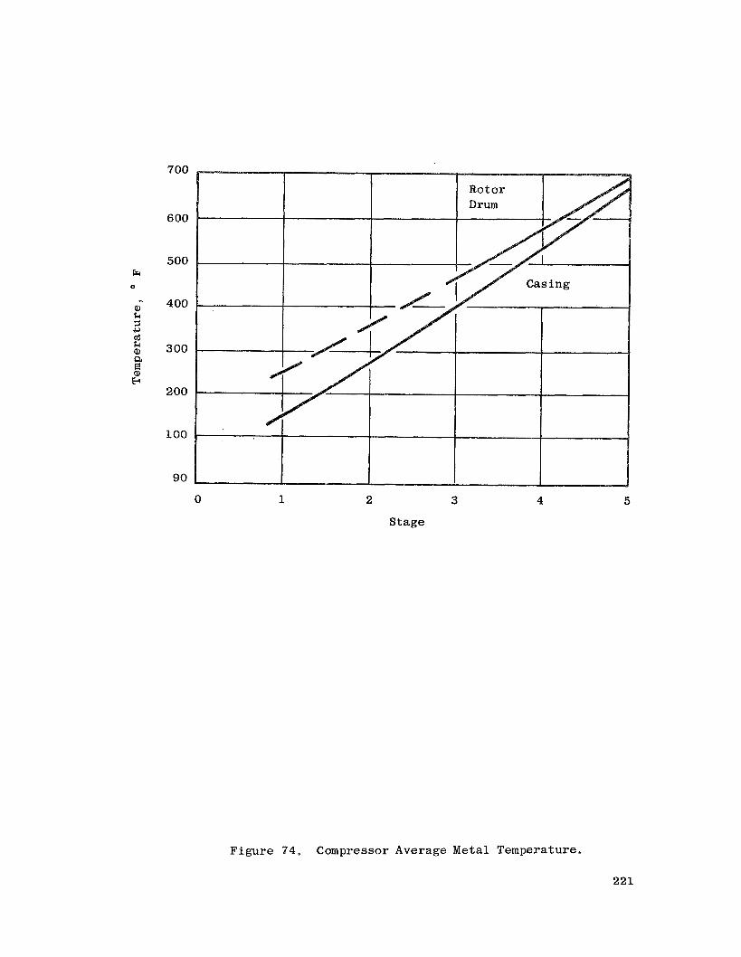
700
6 00
500
400
3 00
200
100
90
0 1 2 3
Stage
4
Figure 74. Compressor Average Metal Temperature.
5
221

7” G 6 - cd p:
4 -
2 -
7” G 6 - cd p:
4 -
2 -
I I I -8 -6 -4 -2 0 +2 +4: +6
Axial Coordinate Inches
Figure 75. Combustor Flowpath ILF’lA1.

16
14
12
10
rn Q) &
H 8 rn 5 .rl a (d cz
6
4
2
0 I I
-8 -6 -4 -2 0 +2 +4 +6 +8
Axial Coordiiiat e Inches
Figure 76, Combustor Flow ath ILF2A1 and ILF2A2,
223

14
13
Ilf 12
s
‘c 0 F: H
11 .rl a cd
1 0
9
8 -4 -3 -2 -1 0 1 2 3 4 5
Axial Coordinate Inches
F igure 78. High P res su re Turbine Flowpath ILF2A1 and ILF2A2.
s .rl a cd p:
14
13
12
11
1 0
9
8 -4 -3 -2 -1 0 1 2 3 4 5
Axial Coordinate Inches
F igure 77. High P res su re Turbine Flowpath ILF1A1.
224

4.0
3 . 5
3.0
2 . 5
2 . 0
1.5
1.0
I Ref: NASA SP-36
0.4 0.5
D , Factor
0.6
Figure 79. OGV L o s s V s . D-Factor.
2 25

0 rl
I 0
226

W rl
* rl
cil rl
0 rl
m
W
*
cu
0
c cil 0
m a, .c B H
a, c, cd FI .I+ P
0 0 V rl cd .I+ x 4
22 7

s --I
e rl
N rl
0 rl
m
(9
d
N
0
N I
(9 d N 0 m (9 N 0 a-! d d d
sayou~ snrpax
228

cv r(
0 I 4
0 0 0 Lo r(
0 0 10 I
229

c, c e, B e, M
k 9 z e, E (d k
Frr
230

140 (128)
Anchorages for Main Fuel S t r u t s
-6 Main S t r u t s
In625
F igure 85. Turbine Rear Frame.
23 1
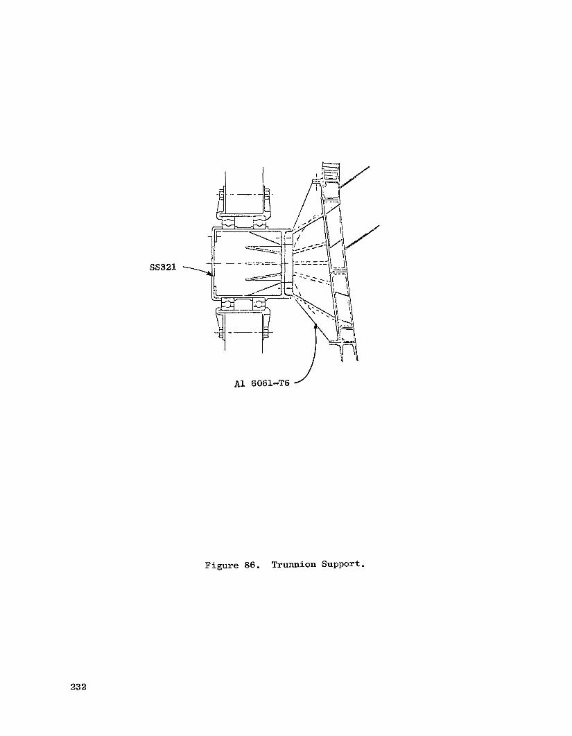
SS321
A1 6061-T6 J
Figure 86. Trunnion Support.
232

32
28
24
0 b,
$2 5
z H
20
.A a cd ffi
16
12
8
12 16 20 24 28 32 36 40
Axial Coordinate Inches
F igure 87. Fan Duct Flowpath I L F l A 1 .
233

32
28
24
20
16
12
8
12 16 20 24 28 32
Axial Coordinate Inches
36 40
Figure 88. Fan Duct Flowpath ILF2A1.
234

N CI) m cu
cu W r-l
=e 7
0 7
W m
N r n m a , 5 C H
Q) c,
m a 3 N C
.I4 5 k 0 0 V 4
v c d N *I4 x
4
0 N
W rl
cv r-l
235

16
14
12
10
8
6
4
2
0
s
-4 -2 0 2 4 6 8
Axial Coordinate Inches
Figure 90. Core Duct Flowpath ILFlA1.
236
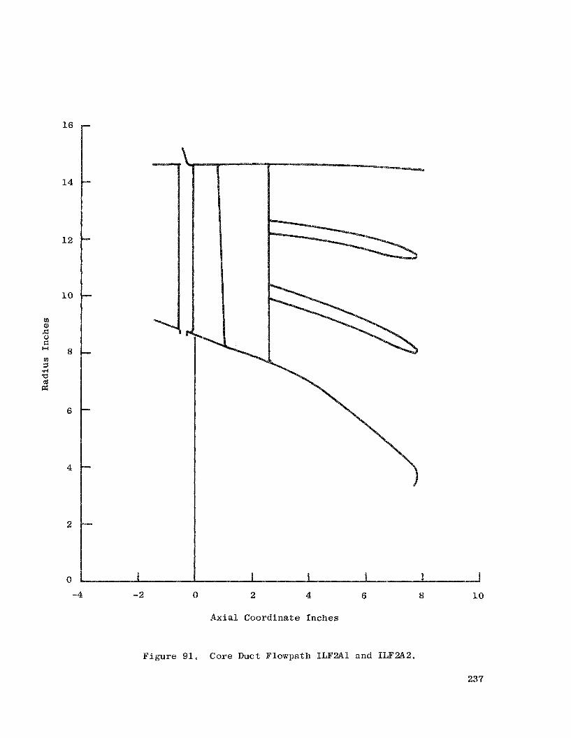
1 6
1 4
12
LO
u1 a,
G 5
z 8 !-I
.rl 5 cd fz
6
4
2
0
D
P
-4 -2 0 2 4 6 8 10
Axial Coordinate Inches
F igure 91. Core Duct Flowpath ILF2A1 and ILF2A2,
237

238

2 39

240

u1 m 0 k u E a, c, 10 R rn c, k 0 a a 7 rn a 3 M G .rl k 0 c, 0 a, +
24 1

a, E: 4 M E: w
I
ol k M a, w E: H
242

k *rl
- 4 k a, -I-’ k cd c, m
k 4 c PI
u n
a 0 cz
xu
a, m .rl 5 k 0
243

+ 4
54 2.- 2.-
rl 0 k c, r: 0 u
244

0 1 2 3 4 5 6 7 8
Pump F l o w , pph x
Figure 99. Pump/Turbine Charac te r i s t i c s .
245

c,
0 I: m
a,
2- 9
bLl s! .rl k Ld a,
k 0 u
a a, c, Ld 0 -4 k P 7 4 rl
Er 3
k 0 c, 0 ffi
s .f: 4
7 E k .rl 4
id 1 c,
Y P a, k Q)
PI 8 rl a, 3 Er
rl 0
a , w ? rl B k -4 4
.rl
Ld z! k .rl 4
a a, 3 rl
0 P= k a, v)
I
d
rl
0 0
246

d 0 d
247

A f t 4c.--..---
0.5
4 C9wn
Forward
C9wn
Side Load 20.5 g .. 6 f, 4 4
2 P i t c h Velocity = 0.1 rad /sec P i t c h Acceleration = 0.5 rad,/sec Roll Velocity = 0.1 rad/sec Ro l l Acceleration = 1.0 rad/sec2
..
NOTES
car, occur i n any combination
1) Load f a c t o r s , angular v e l o c i t i e s and acce le ra t ions t o be
2) 3) 4 )
taken about t h e C.G. of t h e fan . Side load f a c t o r s act t o e i t h e r s ide . Side loads and gyro loads do not act simultaneously. Zero t o maximum t h r u s t f o r all conditions.
Figure 102, Engine Steady Maneuver Load Requirements.
248
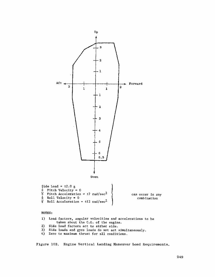
UP
Aft - 2
$. Down
Side Load = 22.0 g 0 Pi tch Velocity = 0 0 4 Roll Velocity = 0 Cp
I.
Pi tch Acceleration = 27 rad/sec2
Roll Acceleration = 212 rad/sec2 ..
-+ Forward 2
can occur i n any comb i n a t ion
NOTES 2
1) Load fac tors , angular v e l o c i t i e s and accelerat ions t o be
2) Side load f a c t o r s act t o e i t h e r s ide. 3) Side loads and gyro loads do not act simultaneously. 4 ) Zero t o maximum thrus t f o r a l l conditions.
taken about t h e C,G. of t h e engine.,
F i g u r e 103. Engine Vertical Landing Maneuver Load Requirements,
249

UP
FLIGHT (0 t o Max. Thrust)
2 0 = -t6 rad/sec
Y = O
Y = O
8 = +_2 rad/sec
S . L . = 4.0 Applicable t o complete crosshatched a rea
Aft
S . L . = 1.5 Applicable t o complete rec tangle from 7 Up t o 10 Down
NOTES :
Down
I
Fore
1)
2 ) 3) 4) 5) 6)
Load f a c t o r s and angular v e l o c i t i e s and acce le ra t ions should be taken a t or about t h e C.G. of the fan. Side load f a c t o r s ( S . L . ) act t o e i t h e r s ide . 8 and 8 a r e p i tch ing ve loc i ty and acce lera t ion . Y and '$! a r e yawing ve loc i ty and acce lera t ion . Down loads occur during p u l l out. Fore load5 occur during a r r e s t e d landing.
Figure 104. Engine Unpowered F l igh t Maneuver Loads.
25 0

Aft 0.75
$ Down
Side Load = +1.0 g 6 Pi tch Velocity = 0.5 raQ,fsec 8 Pi tch Acceleration = 1.0 rad/sec2 6 R o l l Velocity = 0.5 rad/sec 7 R o l l Acceleration = 2-0 rad f sec2
. e
Forward
can occur i n any combinat ion
NOTES : 1)
2) 3) 4)
Load f ac to r s , angular v e l o c i t i e s and accelerat ions t o be
Side load f a c t o r s act t o e i t h e r s ide , Side loads and gyro loads do nor act simultaneously. Zero t o maximum t h rus t f o r a l l conditions.
taken about t h e C.G. of t he engine.
Figure 105. Engine Frequent Maneuver Load Requirements,
251

UP
A f t --
Down
!
Forward
S ide Load = k1.0 g
2 Maximum combined 8 P i t c h Veloci ty = 1.0 rad/sec 0 Pi t ch Accelerat ion = 1.0 rad/sec @ R o l l Veloci ty = 1.0 rad/sec ~
ve loc i ty = 1.0 rad/sec zl
@ R o l l Accelerat ion = 3.0 rad/sec
NOTES :
1) Load f a c t o r s , angular v e l o c i t i e s and acce le ra t ions t o be taken about t h e C.G. of t h e engine.
2) Side load f a c t o r s a c t t o e i t h e r s ide . 3) Side loads and gyro loads do not a c t simultaneously. 4) Zero t o maximum t h r u s t f o r a l l condi t ions.
Figure 106, Engine Infrequent Maneuver Load Requirements.
25 2
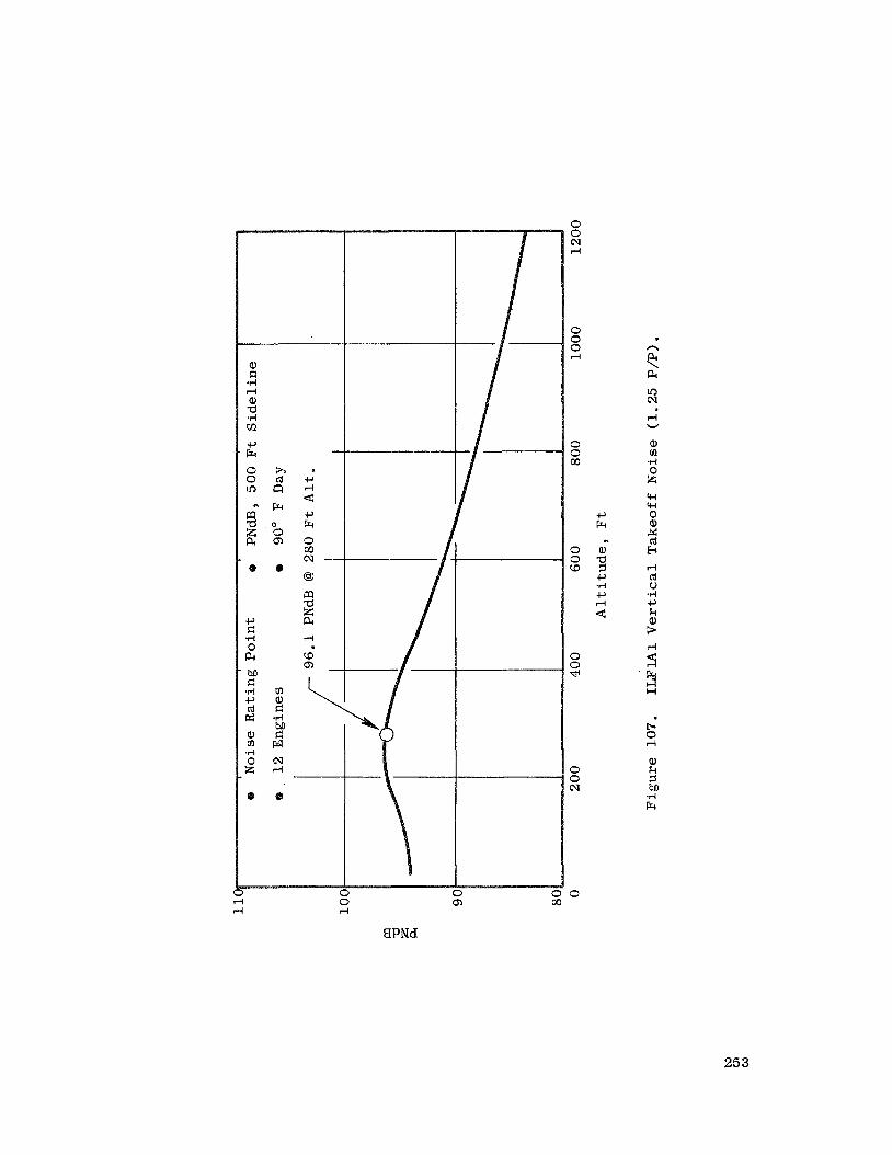
I
I 0 0 I 4
BPNd
0 0 N rl
0 0 0 rl
0 0 (0
0 0 a
0 0 dl
0 0 N
0
n PI \ PI In N
rl W
a, m .PI 0 A
b 0 rl
a, k 3 M .rl Fr
25 3

c, e e ' Fr
0 l-4 d
0 0 rl
0
rl %
0 0 0 d
0 0 co
0 3
3 3 d
3 3 N
3
n c4 \ c4 0 N
rl W
co 0 d
e, k 5 M .d Fr
0 In
0 Go
BPNd
25 4

a, c: .ri rl a, a .I4 VI
P R 0 0 Lo
a a E @
h cd cl Fc
0 0 4
0 0 0 rl
0 0 M
0 0 W
0 0 b(
0 0 cv
0
0 N
rl
a, m *rl 0 x w +I 0
v
0, 0 rl
a, k 5 hl) v i R
0 0 0, 00
%PNd
255
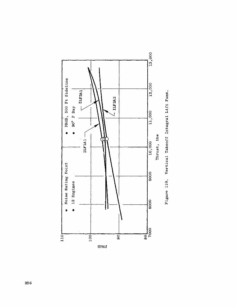
d
3 3 H
m a, E: -4 M E: w
C rl r
0 c cn C
0 0 0 m d
n
0 0 0
N rl
n
0 0 0 r( rl
n
0 0 0
0 d
n
0 0 0 Q,
0 0 0 CQ
0 0 0 E..
m P d
n c, m El k Jz E
8PNd
25 6

c,
T I E: 0 a bsJ E: .rl c, cd 92 a, m
a d
0 A
0
m a, d .d ba E: w N rl
0
In rl rl
0 rl rl
.
In 0
0 0
d rl
10 0 In cn cn cr3
25 7

. m a
c
0 In d 0 rl d
0 In 0 cn rl
0 cn In oc)
ii 3 H
I
.rl m m a, k a a 7 m
9 Fr
cv rl d
a,
2 3 .rl Fr
25 8
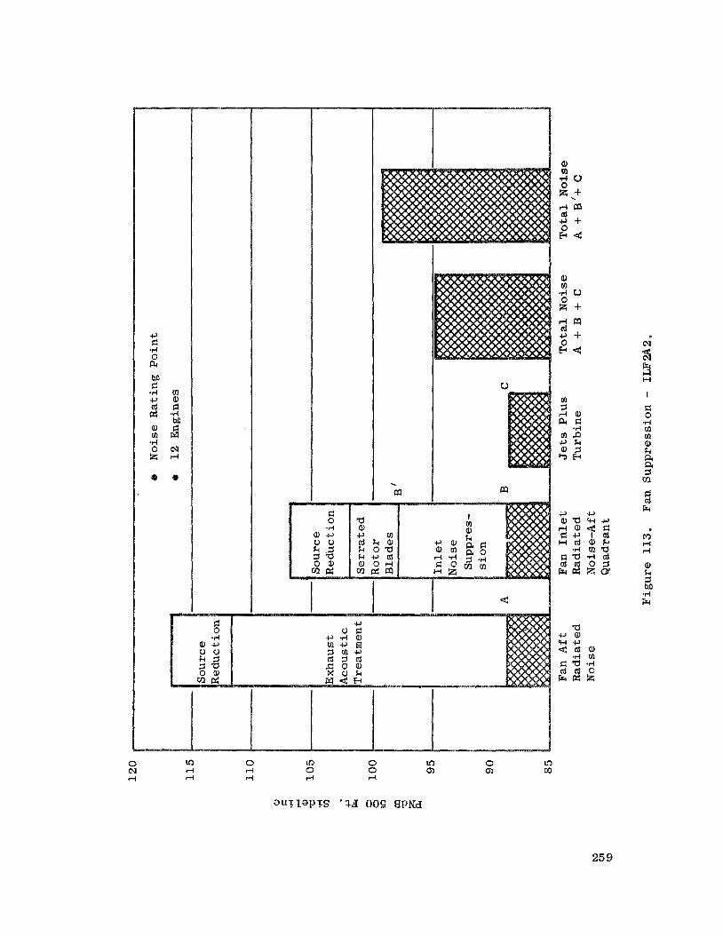
. m
0 I
m
0 In .-I 0 rl Pi
0 In 0 cn .-I
0 cn In m
25 9

a
01 d v1 4
0
n a,
a, k a, w w .rl
2
n a a 0 r( I
W
m 3 m 4: m c, d a, u) a,
a,
0
k
U
260
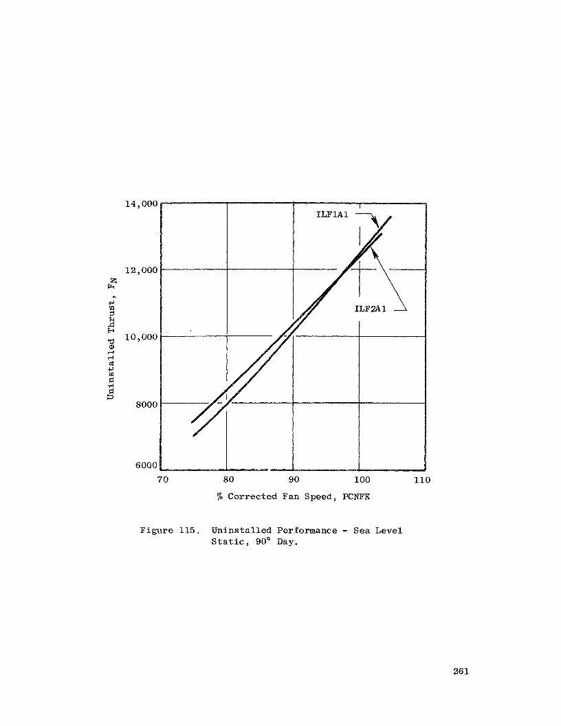
14 , 000
12,000 z
Fr
+-' ul =r k ,.c H P a, d d cd c,
.ri
n
10,000
z E: 3
8000
6000
70 80 90 100 110
% Corrected Fan Speed, PCNFK
Figure 115. Uninstal led Performance - Sea Level S t a t i c , 90' Day.
26 1

P a, c, td p: c, td d Fr P d
0 0
N d
O"
0
N s 0
0 N N
0 0 0 N
0 0 a3 d
0 o',
0 co
0 b
0 CD
0 u3
0 v
0 Cr)
Er 0
n 0
E.r
a, k I c, 03 k a,
n
3 2 c, r: a, .rl P 3
h L-d R P k L-d P r: cd c, m u .rl c, cd c, m d a, 3 a, GI cd a, m I
a,
*
: fi 0 +I k a, a a a, l l d cd c, m c .rl !a 3
CD d d
E z .rl Er
262

0 0 0
Cr) .-I
n
0 0 0
cv rl
-
0 0 o z
- F r rl r l -
c, v1 5 k s! E
0 o c , o a , - z 0 r l a
a, rl rl cd c, m El
0 v-l O F : 0 3 Q)
0 0 0 00
0 0 0 b.
263
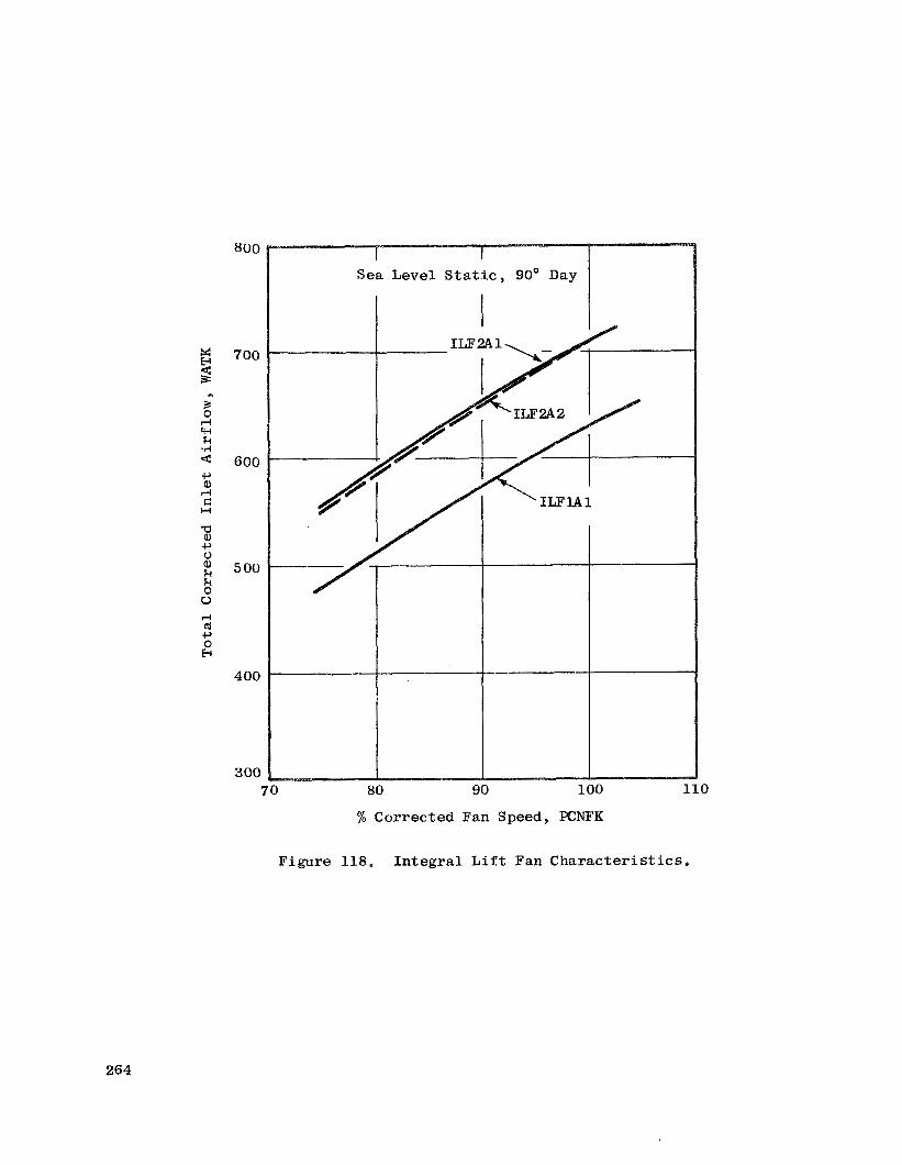
5: E 3 n
rl w k .I4
c, a, Fi r: H
a a, t-, 0 a, k k 0 u
l-i (d c, 0 h
800
700
600
5 00
400
300 70 80 90 100 1
% Corrected Fan Speed, XNFK
Figure 118. Integral L i f t Fan Character is t ics .
0
264

265
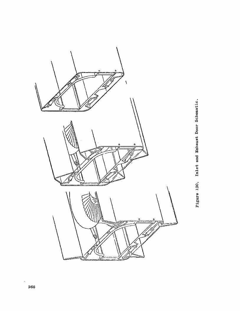
\
k 0 0 n
266
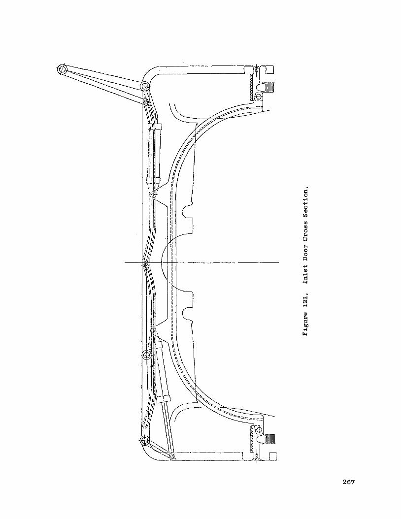
I
7 /j
i !
m
rl CJ d
267

1 /--
----I--
U 1
rn rn 0 k u k 0 0 CI
268

R" 3
269

0 V
_____pp f v2
n
h k a, * 0 u a, cz c, a, r( F H
1.00
0.99
0.98
0.97
0.96 0 1.0 2.0 3.0
Figure 124. O b j e c t i v e - Recovery of Assumed I n l e t Design
270

0.30
0.25
0.20
0.15
0.10
0.05
0 0
I
1.0 2.0 3.0
v0’v2
Figure 125. Ob jec t ive D i s t o r t i o n Parameter of Assumed I n l e t Design.
27 1

0 0 cu
0 00 d
0 CD d
0 * t-l
0 cu d
0 0 d
0 00
0 CD
0 *
8
0
27 2

.. rn k 0 c, 0 (d E a, P.4 cd 0 r%l
u n * n 01 \ PI \ * z= U \ Tb
n * PI \ PI \ * 5 U
W
A
W
V n * $=
73 (d
W \
c, a, d El H
El (d a, d u
u * 3
c, a, d El H
a a, c, k 0 c, rn 2
D
273

c, m 4 cl
n
* ‘d a!
,F
* Values at Peak Eff ic iency N / n = T
“Avg - pMin’/pAvg
N / f i =
100% 90%
80%
70% I I I I I I 0
I
1.0
9 a d U
h a (d *
F W
“Avg - ’Min )P Avg
Figure 128. Crosswind Distortion Ef fec t s on Compressor Performance.
274

* Values at Peak Efficiency
* * E E
c, W .rl n
'j;l n PI \ PI \ * v
&
d r l
nnn* a a ( d a b
3 a, rl u
C F h PI \ PI \ * B U
v
1.0
1.0
3 *v
a, rl
5
1.0
0 c , ( d ml a,
"Avg - pMin)'pAvg
100%
90%
80%
+
N/f i = 60%
70%
80%
90%
100%
"Avg - pMin'/pAvg
Figure 129. Crosswind Di s to r t ion E f f e c t s on Fan Performance.
275

0 1000 2000 3000 4000 5000
Distance, Ft
Figure 130. Typical Takeoff Trajectory.
276

1
h
a a, a, a u1
0 1000 2000 3000 4000 5 000
Distance, F t
F igure 131. Typical Takeoff Trajectory.
277

I I I
- I I I 1 i -
n rl rl
I'
I
I
a Q) I+
rl cd c, m c .I4 c 5
a Q) rl rl d c, m c H
I I I I
0 cu rl
0 0 rl
0 00
0 (D
0 .;r
0 N
0
w 0 c, 0 Q) w w w
cu m rl
Q) : .I4 Er
278

0 cv rl
0 0 rl
0 co
0 CD
0 d
0 cv
0 m
m c, 0 E: M n 0 +
v1 c, la .rl 0
pc h k 0 c, 0 a, .r) cd k rn rl cd 0 .rl a h E k 0 w E: 0 *rl c, cd d d cd c, m E: H
w 0
c, 0 a, w w w
M m rl
a, z .rl Fr
279

0 0 0 0 00 P
0 0 v)
0 0 0 d
280