Application Specification for Starter Kit Tool of RFM9x ... User Guide V1.0_EN.pdf · Application...
17
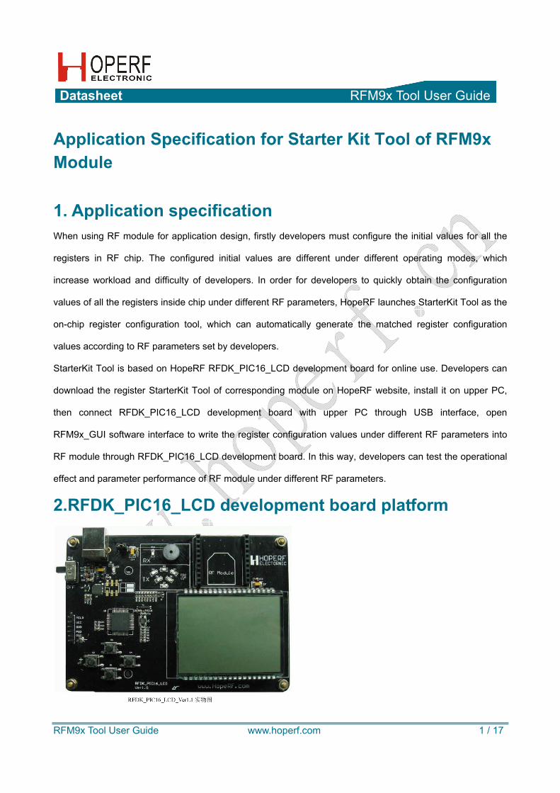
Datasheet RFM9x Tool User Guide RFM9x Tool User Guide www.hoperf.com 1 / 17 Application Specification for Starter Kit Tool of RFM9x Module 1. Application specification When using RF module for application design, firstly developers must configure the initial values for all the registers in RF chip. The configured initial values are different under different operating modes, which increase workload and difficulty of developers. In order for developers to quickly obtain the configuration values of all the registers inside chip under different RF parameters, HopeRF launches StarterKit Tool as the on-chip register configuration tool, which can automatically generate the matched register configuration values according to RF parameters set by developers. StarterKit Tool is based on HopeRF RFDK_PIC16_LCD development board for online use. Developers can download the register StarterKit Tool of corresponding module on HopeRF website, install it on upper PC, then connect RFDK_PIC16_LCD development board with upper PC through USB interface, open RFM9x_GUI software interface to write the register configuration values under different RF parameters into RF module through RFDK_PIC16_LCD development board. In this way, developers can test the operational effect and parameter performance of RF module under different RF parameters. 2.RFDK_PIC16_LCD development board platform
Transcript of Application Specification for Starter Kit Tool of RFM9x ... User Guide V1.0_EN.pdf · Application...
Datasheet RFM9x Tool User Guide
RFM9x Tool User Guide www.hoperf.com 1 / 17
Application Specification for Starter Kit Tool of RFM9x Module 1. Application specification When using RF module for application design, firstly developers must configure the initial values for all the
registers in RF chip. The configured initial values are different under different operating modes, which
increase workload and difficulty of developers. In order for developers to quickly obtain the configuration
values of all the registers inside chip under different RF parameters, HopeRF launches StarterKit Tool as the
on-chip register configuration tool, which can automatically generate the matched register configuration
values according to RF parameters set by developers.
StarterKit Tool is based on HopeRF RFDK_PIC16_LCD development board for online use. Developers can
download the register StarterKit Tool of corresponding module on HopeRF website, install it on upper PC,
then connect RFDK_PIC16_LCD development board with upper PC through USB interface, open
RFM9x_GUI software interface to write the register configuration values under different RF parameters into
RF module through RFDK_PIC16_LCD development board. In this way, developers can test the operational
effect and parameter performance of RF module under different RF parameters.
2.RFDK_PIC16_LCD development board platform
Datasheet RFM9x Tool User Guide
RFM9x Tool User Guide www.hoperf.com 2 / 17
RFDK_PIC16_LCD development board platform system is a hardware development platform based on
PIC16 series single chip processor of Microchip Company. The software development environment is MPLAB
IDE v8.86; It is applicable for all the RF module products of HopeRF and supports off-line operation. It only
supports Lora operation mode under on-line state, but supports 2 operation modes including Lora and
ordinary under off-line state.
RFDK_PIC16_LCD development board is a DEMO function board, inside which there is DEMO software
system. Firstly, developers need load the module product. Only after doing so, can they online use StarterKit
tool, with specific steps as follows:
The first step: download corresponding DK_StarterKit.rar from website of our company and save it under root
directory and uncompress RFM9x_GUI_DK_Firmware_140303.hex file;
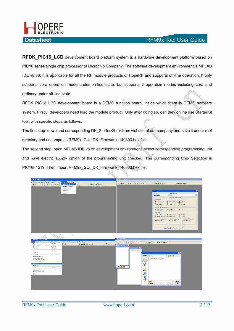
The second step: open MPLAB IDE v8.86 development environment, select corresponding programming unit
and have electric supply option of the programming unit checked. The corresponding Chip Selection is
PIC16F1519. Then import RFM9x_GUI_DK_Firmware_140303.hex file;
Datasheet RFM9x Tool User Guide
RFM9x Tool User Guide www.hoperf.com 3 / 17
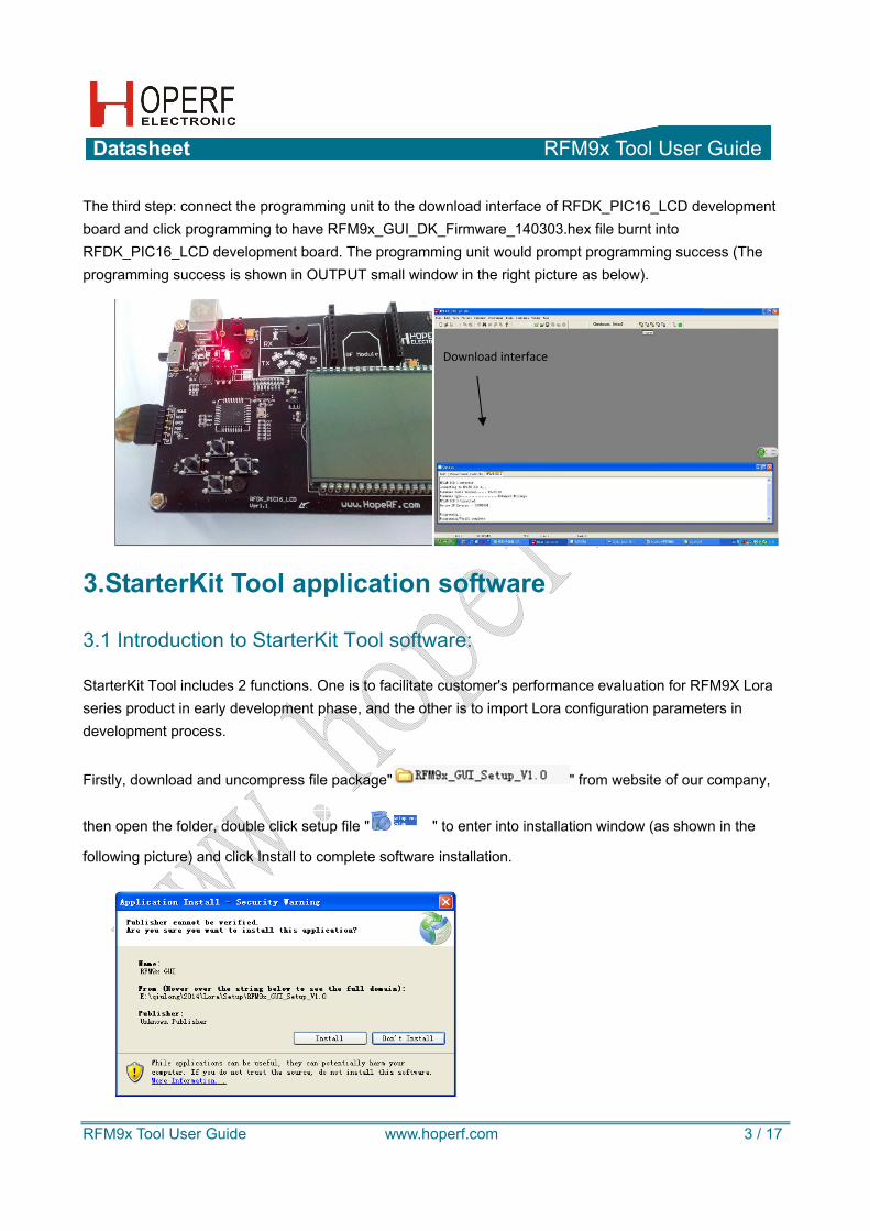
The third step: connect the programming unit to the download interface of RFDK_PIC16_LCD development board and click programming to have RFM9x_GUI_DK_Firmware_140303.hex file burnt into RFDK_PIC16_LCD development board. The programming unit would prompt programming success (The programming success is shown in OUTPUT small window in the right picture as below).
3.StarterKit Tool application software
3.1 Introduction to StarterKit Tool software:
StarterKit Tool includes 2 functions. One is to facilitate customer's performance evaluation for RFM9X Lora series product in early development phase, and the other is to import Lora configuration parameters in development process.
Firstly, download and uncompress file package" " from website of our company,
then open the folder, double click setup file " " to enter into installation window (as shown in the
following picture) and click Install to complete software installation.
Download interface

Datasheet RFM9x Tool User Guide
RFM9x Tool User Guide www.hoperf.com 4 / 17
The following picture is StartKit Tool software window.
Schematic diagram for StartKit tool window
3.3 Menu tool The menu toolkit includes two menus: file menu and about
menu;
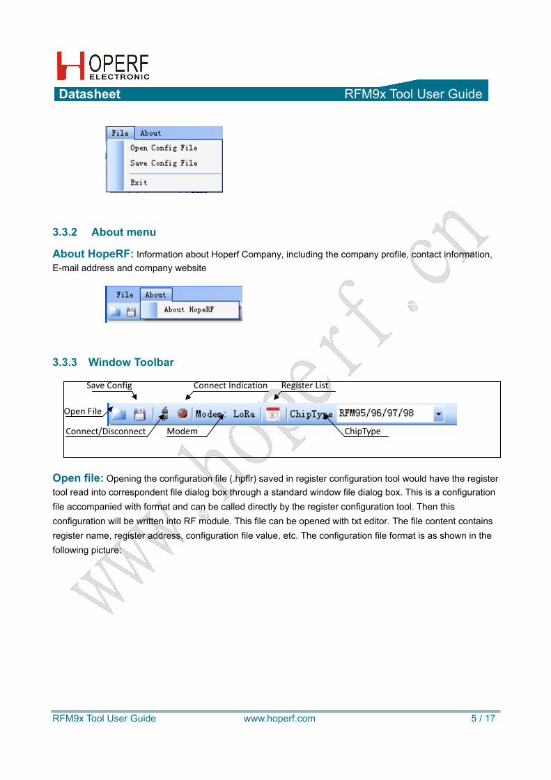
3.3.1 File menu
Open Config: Opening the configuration file (.hpflr) saved in StartKit Tool would have the register tool read into correspondent file dialog box through a standard window file dialog box and then have this configuration written into RF module. This function can also be realized through Open File in window toolbar.
Save Config: Save the configuration file (.hpflr) of current RF module in register configuration tool, which is realized through a standard window file dialog box. The default filename is the last configuration file saved.
Exit: Exit from current application.
Datasheet RFM9x Tool User Guide
RFM9x Tool User Guide www.hoperf.com 5 / 17
3.3.2 About menu
About HopeRF: Information about Hoperf Company, including the company profile, contact information, E-mail address and company website
3.3.3 Window Toolbar
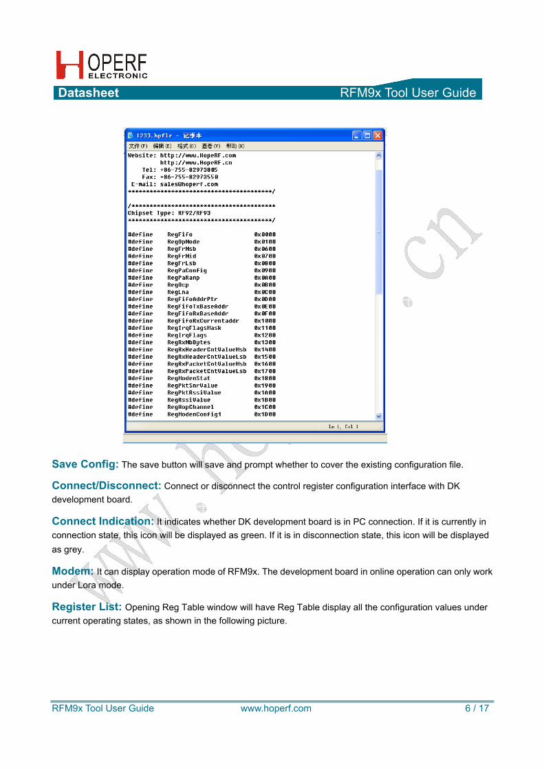
Open file: Opening the configuration file (.hpflr) saved in register configuration tool would have the register tool read into correspondent file dialog box through a standard window file dialog box. This is a configuration file accompanied with format and can be called directly by the register configuration tool. Then this configuration will be written into RF module. This file can be opened with txt editor. The file content contains register name, register address, configuration file value, etc. The configuration file format is as shown in the following picture:
Save Config
Connect/Disconnect
Open File
Modem
Connect Indication Register List
ChipType
Datasheet RFM9x Tool User Guide
RFM9x Tool User Guide www.hoperf.com 6 / 17
Save Config: The save button will save and prompt whether to cover the existing configuration file.
Connect/Disconnect: Connect or disconnect the control register configuration interface with DK development board.
Connect Indication: It indicates whether DK development board is in PC connection. If it is currently in connection state, this icon will be displayed as green. If it is in disconnection state, this icon will be displayed as grey.
Modem: It can display operation mode of RFM9x. The development board in online operation can only work under Lora mode.
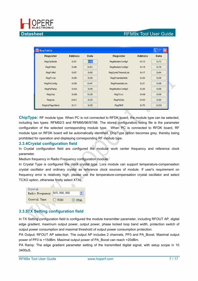
Register List: Opening Reg Table window will have Reg Table display all the configuration values under current operating states, as shown in the following picture.
Datasheet RFM9x Tool User Guide
RFM9x Tool User Guide www.hoperf.com 7 / 17
ChipType: RF module type. When PC is not connected to RFDK board, the module type can be selected, including two types: RFM92/3 and RFM95/96/97/98. The stored configuration listing file is the parameter configuration of the selected corresponding module type. When PC is connected to RFDK board, RF module type on RFDK board will be automatically identified. ChipType option becomes grey, thereby being prohibited for operation and displaying corresponding RF module type. 3.3.4Crystal configuration field In Crystal configuration field are configured the modular work center frequency and reference clock parameter. Medium frequency in Radio Frequency configuration module. In Crystal Type is configured the clock crystal type. Lora module can support temperature-compensation crystal oscillator and ordinary crystal as reference clock sources of module. If user's requirement on frequency error is relatively high, please use the temperature-compensation crystal oscillator and select TCXO option, otherwise firstly select XTAL.
3.3.5TX Setting configuration field
In TX Setting configuration field is configured the module transmitter parameter, including RFOUT AP, digital edge gradient, maximum output power, output power, phase locked loop band width, protection switch of output power consumption and maximal threshold of output power consumption protection. PA Output: RFOUT AP selection. The output AP includes 2 channels, PF0 and PA_Boost. Maximal output power of PF0 is +15dBm. Maximal output power of PA_Boost can reach +20dBm. PA Ramp: The edge gradient parameter setting of the transmitted digital signal, with setup scope in 10 3400uS.
Datasheet RFM9x Tool User Guide
RFM9x Tool User Guide www.hoperf.com 8 / 17
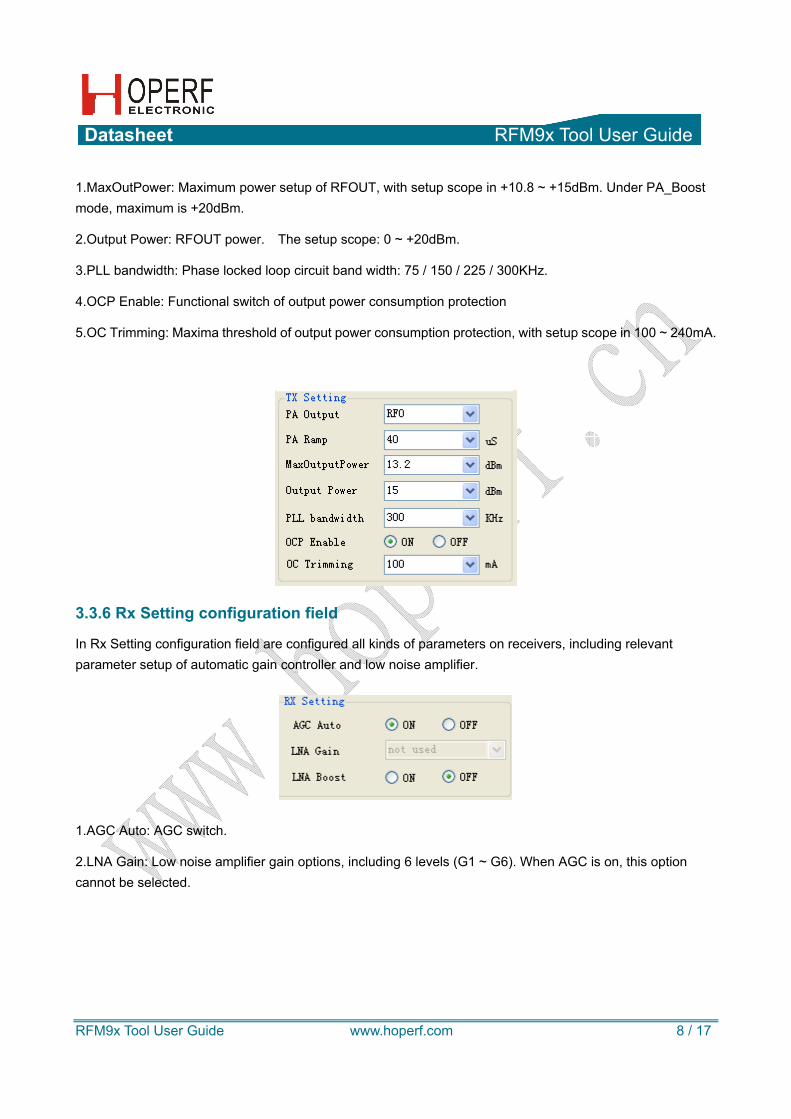
1.MaxOutPower: Maximum power setup of RFOUT, with setup scope in +10.8 ~ +15dBm. Under PA_Boost mode, maximum is +20dBm.
2.Output Power: RFOUT power. The setup scope: 0 ~ +20dBm.
3.PLL bandwidth: Phase locked loop circuit band width: 75 / 150 / 225 / 300KHz.
4.OCP Enable: Functional switch of output power consumption protection
5.OC Trimming: Maxima threshold of output power consumption protection, with setup scope in 100 ~ 240mA.
3.3.6 Rx Setting configuration field
In Rx Setting configuration field are configured all kinds of parameters on receivers, including relevant parameter setup of automatic gain controller and low noise amplifier.
1.AGC Auto: AGC switch.
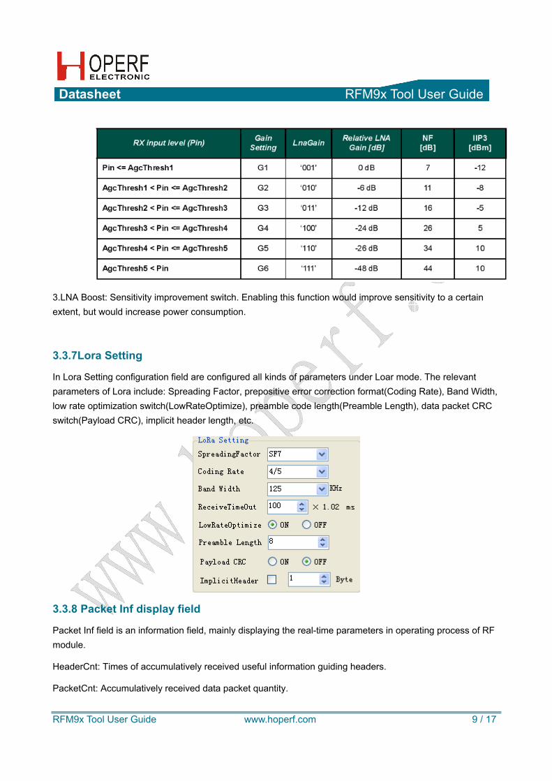
2.LNA Gain: Low noise amplifier gain options, including 6 levels (G1 ~ G6). When AGC is on, this option cannot be selected.
Datasheet RFM9x Tool User Guide
RFM9x Tool User Guide www.hoperf.com 9 / 17
3.LNA Boost: Sensitivity improvement switch. Enabling this function would improve sensitivity to a certain extent, but would increase power consumption.
3.3.7Lora Setting
In Lora Setting configuration field are configured all kinds of parameters under Loar mode. The relevant parameters of Lora include: Spreading Factor, prepositive error correction format(Coding Rate), Band Width, low rate optimization switch(LowRateOptimize), preamble code length(Preamble Length), data packet CRC switch(Payload CRC), implicit header length, etc.
3.3.8 Packet Inf display field
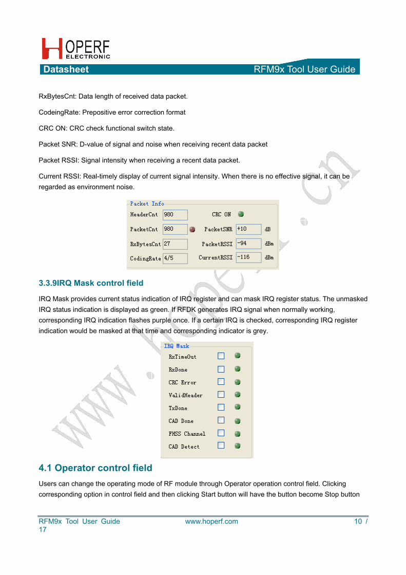
Packet Inf field is an information field, mainly displaying the real-time parameters in operating process of RF module.
HeaderCnt: Times of accumulatively received useful information guiding headers.
PacketCnt: Accumulatively received data packet quantity.
Datasheet RFM9x Tool User Guide
RFM9x Tool User Guide www.hoperf.com 10 / 17
RxBytesCnt: Data length of received data packet.
CodeingRate: Prepositive error correction format
CRC ON: CRC check functional switch state.
Packet SNR: D-value of signal and noise when receiving recent data packet
Packet RSSI: Signal intensity when receiving a recent data packet.
Current RSSI: Real-timely display of current signal intensity. When there is no effective signal, it can be regarded as environment noise.
3.3.9IRQ Mask control field
IRQ Mask provides current status indication of IRQ register and can mask IRQ register status. The unmasked IRQ status indication is displayed as green. If RFDK generates IRQ signal when normally working, corresponding IRQ indication flashes purple once. If a certain IRQ is checked, corresponding IRQ register indication would be masked at that time and corresponding indicator is grey.
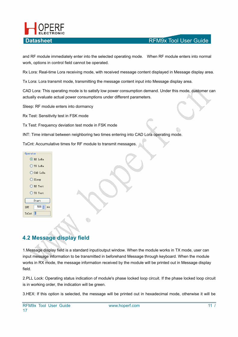
4.1 Operator control field Users can change the operating mode of RF module through Operator operation control field. Clicking corresponding option in control field and then clicking Start button will have the button become Stop button
Datasheet RFM9x Tool User Guide
RFM9x Tool User Guide www.hoperf.com 11 / 17
and RF module immediately enter into the selected operating mode. When RF module enters into normal work, options in control field cannot be operated.
Rx Lora: Real-time Lora receiving mode, with received message content displayed in Message display area.
Tx Lora: Lora transmit mode, transmitting the message content input into Message display area.
CAD Lora: This operating mode is to satisfy low power consumption demand. Under this mode, customer can actually evaluate actual power consumptions under different parameters.
Sleep: RF module enters into dormancy
Rx Test: Sensitivity test in FSK mode
Tx Test: Frequency deviation test mode in FSK mode
INT: Time interval between neighboring two times entering into CAD Lora operating mode.
TxCnt: Accumulative times for RF module to transmit messages.
4.2 Message display field
1.Message display field is a standard input/output window. When the module works in TX mode, user can input message information to be transmitted in beforehand Message through keyboard. When the module works in RX mode, the message information received by the module will be printed out in Message display field.
2.PLL Lock: Operating status indication of module's phase locked loop circuit. If the phase locked loop circuit is in working order, the indication will be green.
3.HEX: If this option is selected, the message will be printed out in hexadecimal mode, otherwise it will be

Datasheet RFM9x Tool User Guide
RFM9x Tool User Guide www.hoperf.com 12 / 17
printed out in ASCII code mode.
4.NewLine: If this option is selected, each time the module transmits the message content; it will be printed in auto linefeed mode.
5.Clear: Clicking this button will clear all the message information in Message display field.
4.3 On-line operation of StarterKit tool and RFDK board:
RFDK board is connected to computer through USB interface. USB / battery power supply can be adopted. Holding down key S1 and turning on power switch will have "—PC - - " displayed on display screen of RFDK
board, namely entering into PC on-line operating mode. Open " " software on PC to enter into RFM9x GUI window, and then click Connect/ Disconnect control key. LCD screen display on RFDK development board is as follows:
Indicator 1 indicates that RFDK board enters into PC on-line operating mode. Indicator 2 indicates that RFDK board works in Lora mode.
5.Off-line operation of RFDK board:
Turning on power switch of RFDK board would directly enter into offline mode, under which mode RF module on RFDK board can work in 2 modes, Lora and ordinary FSK.
12
Datasheet RFM9x Tool User Guide
RFM9x Tool User Guide www.hoperf.com 13 / 17
Under off-line operating mode, switching between Lora and FSK modes, configuring parameters, switching all kinds of test modes and other operations can be completed through four keys S1, S2, S3 and S4 on RFDK board.
Four test modes:
1.FSK straight through normal receiving mode: is to facilitate evaluation of RF module's receiving sensitivity. The precondition of entering into this mode is under normal FSK mode.
2.Lora receiving mode: supports reception for the signal of vector signal generator, thereby being able to test Lora receiving sensitivity. The precondition of entering into this mode is operation under Lora mode.
3.0 frequency test mode: is to facilitate test carrier frequency of RF module.
4.Frequency deviation test mode is to facilitate test of Fdev parameter.
5.1 Parameter configuration
When RFDK is under off-line operating mode, users can realize parameter setting for RFDK board through keystroke operation, with concrete operation steps as follows:
1.When RFDK board is under normal operating conditions, long press key S3 till RFDK board issues Bi sound, meanwhile digital code segment in frequency band where display center frequency is located and front three digital codes in display frequency are jumping, which indicate that RFDK board has already entered into parameter configuration mode.
2.After entering into configuration mode, select the configuration parameter through short press key S3. The display segment of selected parameter would jump.
3.Short press key S2 (-) or S4 (+) can change the selected parameter value.
4.Short press key S1 can quit the parameter configuration mode.
5.2 FSK operating mode:
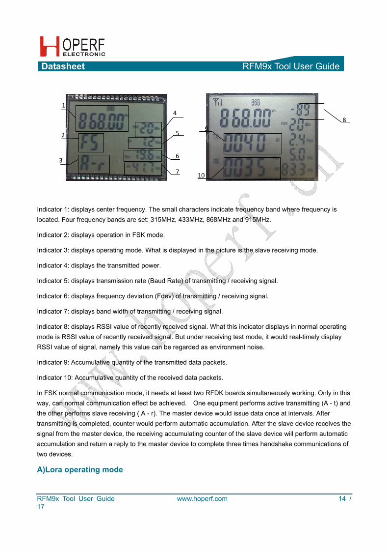
After starting up, LCD will display current configuration parameters, including center frequency point, operating mode, transmit-receive operating status, strength of transmitting / receiving signal, baud rate, frequency deviation, band width, etc. The display on LCD screen under FSK operating mode is shown in the picture below.
Datasheet RFM9x Tool User Guide
RFM9x Tool User Guide www.hoperf.com 14 / 17
Indicator 1: displays center frequency. The small characters indicate frequency band where frequency is located. Four frequency bands are set: 315MHz, 433MHz, 868MHz and 915MHz.
Indicator 2: displays operation in FSK mode.
Indicator 3: displays operating mode. What is displayed in the picture is the slave receiving mode.
Indicator 4: displays the transmitted power.
Indicator 5: displays transmission rate (Baud Rate) of transmitting / receiving signal.
Indicator 6: displays frequency deviation (Fdev) of transmitting / receiving signal.
Indicator 7: displays band width of transmitting / receiving signal.
Indicator 8: displays RSSI value of recently received signal. What this indicator displays in normal operating mode is RSSI value of recently received signal. But under receiving test mode, it would real-timely display RSSI value of signal, namely this value can be regarded as environment noise.
Indicator 9: Accumulative quantity of the transmitted data packets.
Indicator 10: Accumulative quantity of the received data packets.
In FSK normal communication mode, it needs at least two RFDK boards simultaneously working. Only in this way, can normal communication effect be achieved. One equipment performs active transmitting (A - t) and the other performs slave receiving ( A - r). The master device would issue data once at intervals. After transmitting is completed, counter would perform automatic accumulation. After the slave device receives the signal from the master device, the receiving accumulating counter of the slave device will perform automatic accumulation and return a reply to the master device to complete three times handshake communications of two devices.
A)Lora operating mode
1
2
3
4
5
6
7
89
10
Datasheet RFM9x Tool User Guide
RFM9x Tool User Guide www.hoperf.com 15 / 17
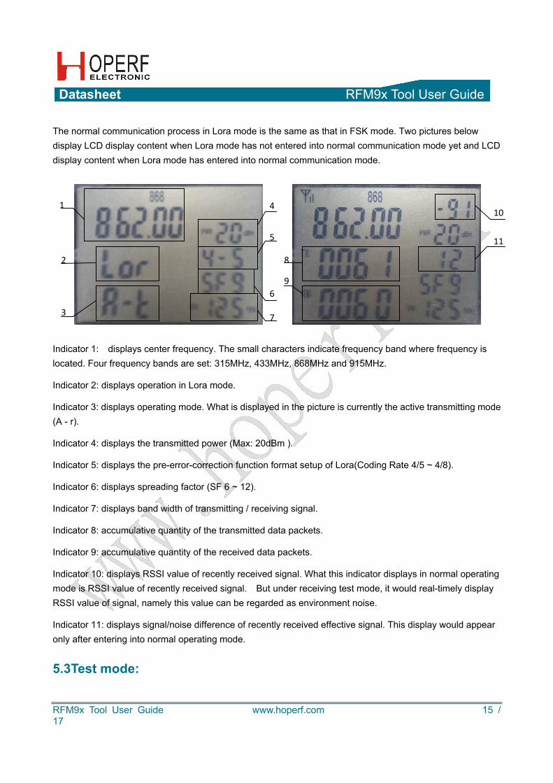
The normal communication process in Lora mode is the same as that in FSK mode. Two pictures below display LCD display content when Lora mode has not entered into normal communication mode yet and LCD display content when Lora mode has entered into normal communication mode.
Indicator 1: displays center frequency. The small characters indicate frequency band where frequency is located. Four frequency bands are set: 315MHz, 433MHz, 868MHz and 915MHz.
Indicator 2: displays operation in Lora mode.
Indicator 3: displays operating mode. What is displayed in the picture is currently the active transmitting mode (A - r).
Indicator 4: displays the transmitted power (Max: 20dBm ).
Indicator 5: displays the pre-error-correction function format setup of Lora(Coding Rate 4/5 ~ 4/8).
Indicator 6: displays spreading factor (SF 6 ~ 12).
Indicator 7: displays band width of transmitting / receiving signal.
Indicator 8: accumulative quantity of the transmitted data packets.
Indicator 9: accumulative quantity of the received data packets.
Indicator 10: displays RSSI value of recently received signal. What this indicator displays in normal operating mode is RSSI value of recently received signal. But under receiving test mode, it would real-timely display RSSI value of signal, namely this value can be regarded as environment noise.
Indicator 11: displays signal/noise difference of recently received effective signal. This display would appear only after entering into normal operating mode.
5.3Test mode:
1
2
3
4
5
6
7
8
9
10
11
Datasheet RFM9x Tool User Guide
RFM9x Tool User Guide www.hoperf.com 16 / 17
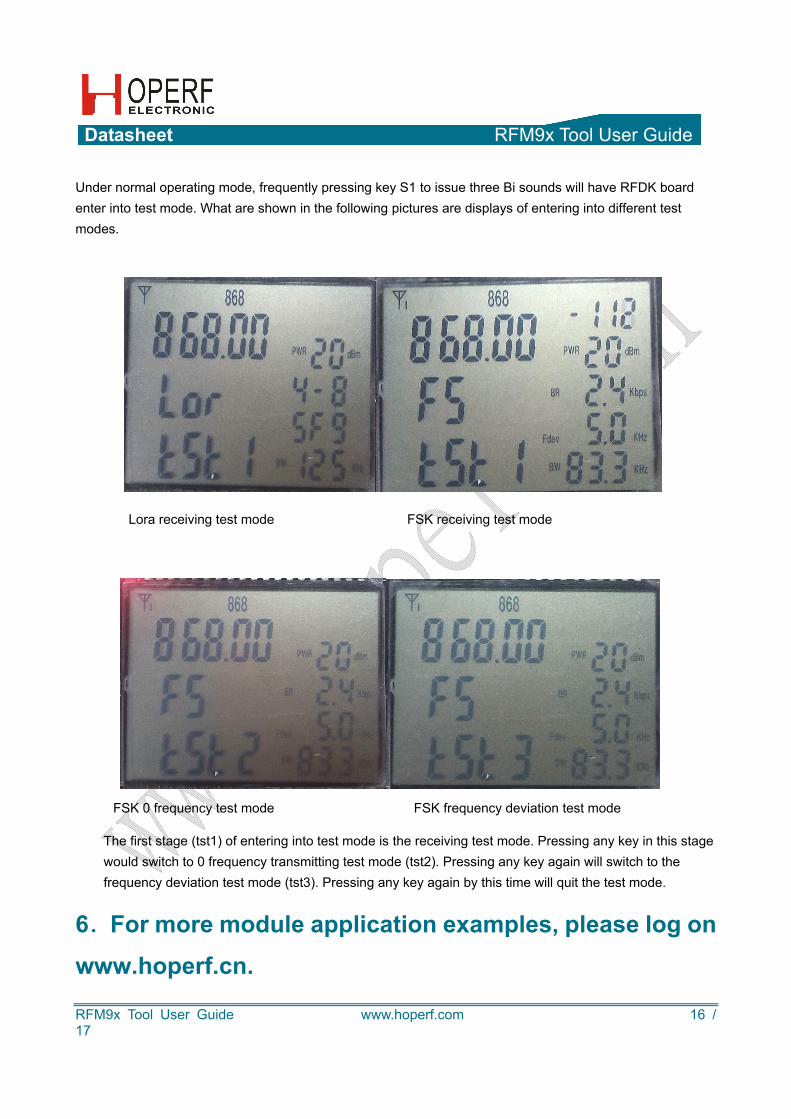
Under normal operating mode, frequently pressing key S1 to issue three Bi sounds will have RFDK board enter into test mode. What are shown in the following pictures are displays of entering into different test modes.
Lora receiving test mode FSK receiving test mode
The first stage (tst1) of entering into test mode is the receiving test mode. Pressing any key in this stage would switch to 0 frequency transmitting test mode (tst2). Pressing any key again will switch to the frequency deviation test mode (tst3). Pressing any key again by this time will quit the test mode.
6.For more module application examples, please log on
www.hoperf.cn.
FSK 0 frequency test mode FSK frequency deviation test mode

Datasheet RFM9x Tool User Guide
RFM9x Tool User Guide www.hoperf.com 17 / 17
HOPE MICROELECTRONICS CO.,LTD Add: 2/F, Building 3, Pingshan Private Enterprise Science and Technology Park, Lishan Road, XiLi Town, Nanshan District, Shenzhen, Guangdong, China Tel: 86-755-82973805 Fax: 86-755-82973550 Email: [email protected] Website: http://www.hoperf.com http://www.hoperf.cn
This document may contain preliminary information and is subject to change by Hope Microelectronics without notice. Hope Microelectronics assumes no responsibility or liability for any use of the information contained herein. Nothing in this document shall operate as an express or implied license or indemnity under the intellectual property rights of Hope Microelectronics or third parties. The products described in this document are not intended for use in implantation or other direct life support applications where malfunction may result in the direct physical harm or injury to persons. NO WARRANTIES OF ANY KIND, INCLUDING, BUT NOT LIMITED TO, THE IMPLIED WARRANTIES OF MECHANTABILITY OR FITNESS FOR A ARTICULAR PURPOSE, ARE OFFERED IN THIS DOCUMENT. ©2006, HOPE MICROELECTRONICS CO.,LTD. All rights reserved.