
Application-Specific Heat Pipe Design and Performance Considerations · 2015-08-19 ·...
17
GSFC· 2015 Application-Specific Heat Pipe Design and Performance Considerations Jesse Maxwell Timothy Holman US Naval Research Laboratory
Transcript of Application-Specific Heat Pipe Design and Performance Considerations · 2015-08-19 ·...

GSFC· 2015
Application-Specific
Heat Pipe Design and
Performance
Considerations
Jesse Maxwell
Timothy Holman
US Naval Research Laboratory

Abstract
A theoretical model is developed for quasi-
one-dimensional constant conductance heat pipes
(CCHP) with non-Darcian wicks in steady state and
solved numerically with state-dependent working
fluid properties across operational temperature for
various parameters. It is demonstrated that
preferential configurations exist for maximizing
heat transfer capability or minimizing temperature
gradients overall or in consideration of design or
manufacturing constraints.

Heat Pipe
Features
• Sealed container
• Working fluid, liquid & vapor phases
• Saturated capillary wick
Principle of Operation
• Liquid evaporates at evaporator
• Vapor advects through adiabatic section
• Vapor condenses at condenser
• Liquid flows in wick back to evaporator
• Continuous cycle
Sintered Grooved
Mesh

Heat Pipe
Advantages
• Operates with or against gravity, or micro-g
• Can approach 101-104x the thermal conductivity of solid Copper
• No moving mechanical parts → high reliability
Disadvantages
• Limited operational temperature range
• Surface tension & contact angle affect performance
• Restricts fluid & solid material choices
• High sensitivity to fluid-wick/wall compatibility
• Wick is complex & expensive
• Limited configurability

Working Fluids
Performance Limitations
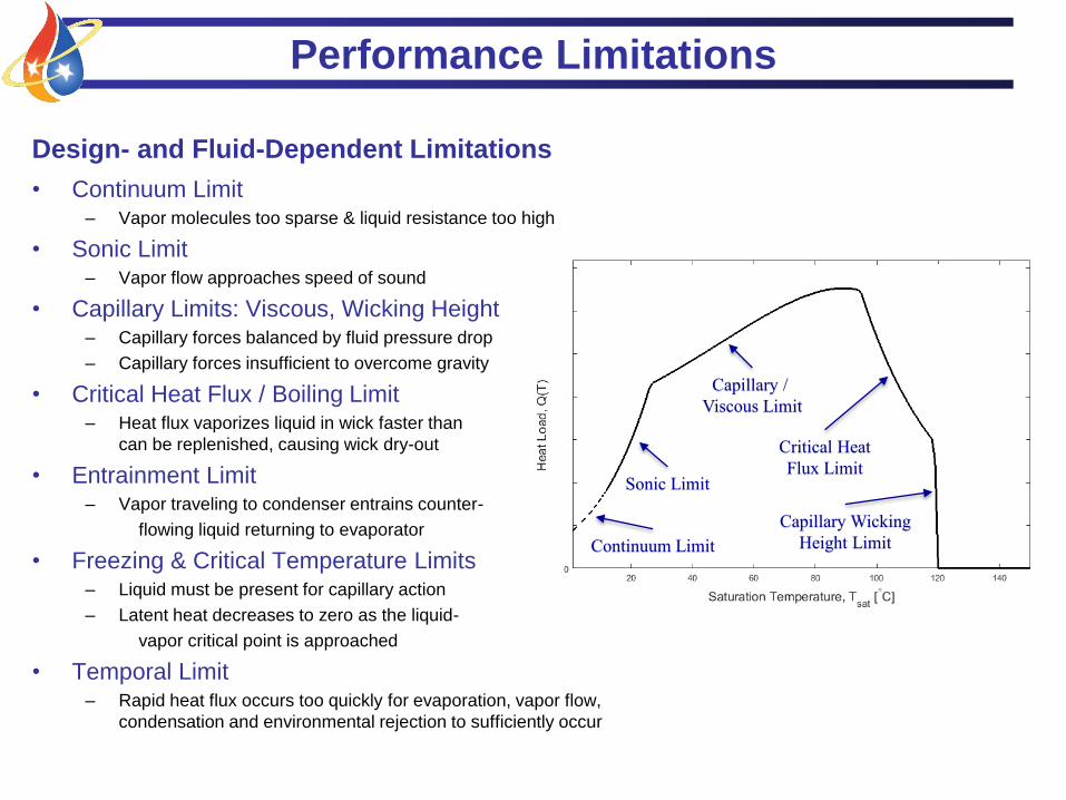
Design- and Fluid-Dependent Limitations
• Continuum Limit– Vapor molecules too sparse & liquid resistance too high
• Sonic Limit– Vapor flow approaches speed of sound
• Capillary Limits: Viscous, Wicking Height – Capillary forces balanced by fluid pressure drop
– Capillary forces insufficient to overcome gravity
• Critical Heat Flux / Boiling Limit– Heat flux vaporizes liquid in wick faster than
can be replenished, causing wick dry-out
• Entrainment Limit– Vapor traveling to condenser entrains counter-
flowing liquid returning to evaporator
• Freezing & Critical Temperature Limits– Liquid must be present for capillary action
– Latent heat decreases to zero as the liquid-
vapor critical point is approached
• Temporal Limit– Rapid heat flux occurs too quickly for evaporation, vapor flow,
condensation and environmental rejection to sufficiently occur
Sonic Limit
Capillary /
Viscous Limit
Critical Heat
Flux Limit
Capillary Wicking
Height LimitContinuum Limit

System Model
• Quasi-one-dimensional
– Radially symmetric
– Large aspect ratio
• Constant, uniform heat fluxes
• Wick model
– Homogeneous, an/isotropic structure
• Separate radial & axial porosity
– Inlet/outlet pressure drop
– Perfect volume saturation
• Phase change model
– Sudden expansion/contraction
– All phase change at wick ID
• Case model
– Homogeneous solid
– Radial heat conduction
– Contact conductance
• Fluid model
– Radially symmetric, quasi-1D
– State-dependent properties
– Capillary action & viscous flow
through uniform, round channels
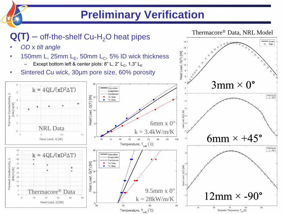
3mm × 0°
6mm × +45°
Preliminary Verification
12mm × -90°
Thermacore® Data, NRL Model
k = 3.4kW/m/K
6mm x 0°
k = 28kW/m/K
9.5mm x 0°Thermacore® Data
NRL Data
Q(T) – off-the-shelf Cu-H2O heat pipes
• OD x tilt angle
• 150mm L, 25mm LE, 50mm LC, 5% ID wick thickness– Except bottom left & center plots: 8” L, 2” LC, 1.3” LE
• Sintered Cu wick, 30µm pore size, 60% porosity

Preliminary Results
• Standard Q(Tsat) plots– All examples provided are for 150mm length and sintered Cu-H2O, 25mm LE and 50mm LC
• Parametrically mapped contours
• Preferential operating conditions & parameter combinations
• Parameter sweeps and constrained optimization
Sample Output

+90°
Preliminary Results
Q(r,T) ropt = f (T,θ)
-90° -30°
0°

Preliminary Results
Q(θ,T)

Preliminary Results
Q(g,T)

Preliminary Results
• Dependence on load factor [g](gadjusted is shifted so that Q(g=0) = 0)
– Varies by fluid and temperature
• Water: Q ~ f (g’0.51)
• Ammonia: Q ~ f (g’0.58)
• R134a: Q ~ f (g’0.59)
For this sample configuration
• 6mm OD x 150mm L, 25mm LE, 50mm LC
5% OD wick thickness
Could be configuration-dependent
• Methods to increase load factor– Increase favorable tilt angle
• Limited to 1 [g]
– Increase acceleration
• Linear: speed up / slow down
• Centripetal: rotation rate, axial distance
e.g. turbine blade
gadjusted = g + gcapillary

Off-The-Shelf Copper-Water Heat Pipe
• 6mm OD x 150mm Long
• 0° inclination
• 25mm evaporator
• 50mm condenser
• 0.5mm wall thickness
• 25μm pore size
• 60% porosity
• 4.7mm vapor space diameter
• keff = 5.2 kW/m/K
Optimize: Custom Heat Pipe Goal: maximize performance, Tevap ≤ 150°C
Must be tolerant to +/- 15° tilt
Minimum size constraint on pore size: 25μm
Fixed porosity, wall thickness, lengths, outer diameter, wall/wick material, fluid (water)
Variables: pore size, vapor channel diameter
Case Study

Case Study
Baseline COTS Heat Pipe
• 38W at Te = 150°C
Custom Heat Pipe
Set θ = 0,-15° and maximize
Q(r,dv) subject to Te ≤ 150°C
• 34μm pore size
• 3.3mm vapor space diameter
• 68W at Te = 150°C
– 67W at -15°, Te = 150°C
• 56% higher heat transfer
• keff = 5.1 kW/m/K – ~13x kCu
– Lower than baseline case
• OR operate at same Q – Te(Q=38W) = 97°C → 53°C cooler

Future Work
• Consolidate into design tool & performance maps
– Application-oriented code
• Implement time-dependent solutions
– Derivation is time-dependent
– These results are strictly steady state
• Experimental verification
– Parameter optimization
– Transient operation
• Model start-up dynamics
– Characterize Tmax(t,Q) and Temporal Limit
• Expand to other configurations
– Thermosyphon
– Loop heat pipe

References
• Faghri, A., 1995, Heat Pipe Science and Technology, 1st ed., Taylor &
Francis, Washington, D.C.
• Moody, L.F., “Friction Factors for Pipe Flow,” Transactions of the ASME,
Vol. 66, 1944
• Munson, B.R., et al., Fundamentals of Fluid Mechanics, John Wiley & Sons,
Inc., Hoboken, NJ, 2010
• Streeter, V.L., ed., Handbook of Fluid Dynamics, McGraw-Hill, New York,
1961
• Holman, J.P., Heat Transfer, 10th ed. McGraw-Hill, New York, 2010
• National Institute of Standards and Technology, NIST Chemistry WebBook,
http://webbook.nist.gov/chemistry/fluid/
• Thermacore®, verification data provided with permission
Acknowledgements
• US Naval Research Laboratory
• TTH Research, Inc.
• Thermacore, Inc.


