Application of Systems Modeling Language (SySML) for ... · Application of Systems Modeling...
20
Application of Systems Modeling Language (SySML) for Cognitive Work Analysis in Systems Engineering Design Process Wilfred H. Wells (University of Central Florida, Orlando, USA [email protected]) Waldemar Karwowski (University of Central Florida, Orlando, USA [email protected]) Serge Sala-Diakanda (University of Central Florida, Orlando, USA [email protected]) Kent Williams (University of Central Florida, Orlando, USA [email protected]) Tareq Ahram (University of Central Florida, Orlando, USA [email protected]) James A. Pharmer (Naval Air Warfare Center Training Systems Division, Orlando, USA [email protected]) Abstract: At present time most system engineers do not have access to cognitive work analysis knowledge or training in terms that they could understand and apply in the system design process. This may lead to specifying systems requirements that do not account for cognitive strengths and limitations of the prospective users. This paper proposes integration of cognitive work demands in the systems engineering process through development of a Cognitive Work Analysis (CWA) framework and a Tutorial using Systems Modeling Language (SysML). The CWA framework provides a structured approach for defining, managing, organizing, and modeling cognitive work requirements in systems engineering process. Keywords: Cognitive work analysis, systems engineering, design, tutorial, Systems Modeling Language Category: J.2, J.4, L.3.0, M.4 1 Introduction Developing a set of complete and consistent design requirements is one of the most important steps in the system engineering process [Stoner et al., 2006]. However this Journal of Universal Computer Science, vol. 17, no. 9 (2011), 1261-1280 submitted: 8/1/11, accepted: 28/4/11, appeared: 1/4/11 © J.UCS
Transcript of Application of Systems Modeling Language (SySML) for ... · Application of Systems Modeling...
Application of Systems Modeling Language (SySML) for Cognitive Work Analysis in Systems Engineering
Design Process
Wilfred H. Wells (University of Central Florida, Orlando, USA
Waldemar Karwowski (University of Central Florida, Orlando, USA
Serge Sala-Diakanda (University of Central Florida, Orlando, USA
Kent Williams (University of Central Florida, Orlando, USA
Tareq Ahram (University of Central Florida, Orlando, USA
James A. Pharmer (Naval Air Warfare Center Training Systems Division, Orlando, USA
[email protected]) Abstract: At present time most system engineers do not have access to cognitive work analysis knowledge or training in terms that they could understand and apply in the system design process. This may lead to specifying systems requirements that do not account for cognitive strengths and limitations of the prospective users. This paper proposes integration of cognitive work demands in the systems engineering process through development of a Cognitive Work Analysis (CWA) framework and a Tutorial using Systems Modeling Language (SysML). The CWA framework provides a structured approach for defining, managing, organizing, and modeling cognitive work requirements in systems engineering process. Keywords: Cognitive work analysis, systems engineering, design, tutorial, Systems Modeling Language Category: J.2, J.4, L.3.0, M.4
1 Introduction
Developing a set of complete and consistent design requirements is one of the most important steps in the system engineering process [Stoner et al., 2006]. However this
Journal of Universal Computer Science, vol. 17, no. 9 (2011), 1261-1280submitted: 8/1/11, accepted: 28/4/11, appeared: 1/4/11 © J.UCS
task is becoming much more challenging and critical today as work systems and environment become more complex. Recent evolution of work content towards application of information technologies, such as smart phones, cloud computing, or enterprise resource planning increases the required cognitive skills to effectively manage associated work tasks, and, therefore, amplifies the need for cognitive work analysis. It is also important to establish the correct design requirements early in the beginning of the development process in order to reduce errors and costs throughout the entire system's lifecycle.
Cognitive work requirements are vital for defining system requirements in the design of complex technological or sociotechnical systems [Rasmussen et al., 1990; Vicente, 1999; Naikar et al., 2006] The primary purpose of cognitive work analysis is to identify cognitive task demands in terms of human abilities and limitations, and understand user strategies in performing cognitive tasks, such as decision making, problem solving, and system monitoring. The lack of accounting for cognitive factors during engineering design process often contributes to incomplete system requirements [Department of the Navy, 2001].
In this study, a framework for cognitive work analysis (CWA) has been developed using the Systems Modeling Language (SysML) to address the implementation of cognitive work requirements by system engineers during the engineering design process. The proposed CWA framework considers five different aspects of a system design and its impact on human operators, including specification of how the system will be used, the relevant characteristics of working environment, and human tasks to be performed. In addition, the CWA framework also considers who will be accountable for each task and the level of competency required of the system user. The CWA framework integrates knowledge provided by the relevant models in each phase of system analysis. The results can be used to specify design requirements for developing complex sociotechnical systems, including, but not limited to such problems as training of air traffic controllers, training of airline pilots, development of human interfaces for consumer products, acquisition of large scale military systems, or identification of relevant information for emergency management systems.
Currently, most system engineers do not have access to cognitive work knowledge or training which may lead to inadequate consideration of the cognitive aspects of system design in terms of cognitive strengths, the limitations of the potential users and diminished system performance. Also system engineers may not know what cognitive analysis methods to use which can result in the inadequate allocation of time and budget to cognitive analysis [Stoner et al., 2006]. Sometimes cognitive work requirements are simply being ignored [Department of the Navy, 2001]. To improve the management of satisfying design requirements in the development of complex training systems, the integration of cognitive work requirements with the systems engineering process needs to be improved.
2 Systems Modeling Language
The Systems Modeling Language (SysML) provides a common language for system engineers to model complex systems [OMG, 2011; Holt and Perry, 2008]. SysML is a visual language that can support a model-based design, requirements analysis,
1262 Wells W.H., Karwowski W., Sala-Diakanda S., Williams K., Ahram T., Pharmer J.A. ...

verification and validation for a variety of large scale and complex systems. SysML graphical models incorporate consideration of the system architecture, behavior and functionality which support the specification, analysis, design, verification and validation of a broad range of systems. SysML has four classes of diagrams that can be used to construct system models, i.e.: structure diagrams, behavior diagrams, requirements diagrams, and parametric relationships diagrams. Specifically, these include Activity diagram (act), Block definition diagram (bdd), Internal block diagram (ibd), Package diagram (pkg), Parametric diagram (par), Requirement diagram (req), Sequence diagram (sd), State machine diagram (stm), and Use case diagram (uc).
The Unified Modeling Language (UML) is the most widely used graphical modeling language for software engineering. The software profile of UML has made it impossible to adopt by System Engineers. The problem is that there is no unified view of non-software elements, no standard modeling language for System Engineering. This is where the Systems Modeling Language (SysML) comes into play. Stereotypes can be used to map the concepts to the system domain. Two separate models can be implemented, one in which to model the System Engineering concepts, and another one for the UML model. The problem is how to combine these two models together, which makes using this alternative unacceptable. UML as a modeling language is not enough to express System Engineering and cognitive requirements concepts. Because the System Engineers express the requirements functionally, they need to see this functionality in the design; it is thus clearly that there was a need to combine the Function-Driven System Engineering and Object-Oriented Software Engineering; this is achieved by SysML, which is a general purpose graphical modeling language. SysML can specify complex systems that include hardware, software, data, personnel, procedures, and facilities. Then SysML can specify, analyze, design, verify and validate these systems. SysML reuses a subset of UML 2.0 and also provides additional extensions which are needed to address the requirements of System Engineering [OMG, 2011].
The basic structural elements in SysML are blocks (Figure 1). A block is a description of the system, subsystem, part, function, human or process. The structure diagrams are used to represent the physical structure of the system which includes the hardware, software, data, procedures, personnel and facilities components. Each system component in the structure diagrams is represented by Block Definition Diagrams (BDD) and Internal Block Diagrams (IBD). BDDs are used to describe the hierarchical and component structure of the system. IBDs describe the internal structure of each component which consists of parts, connectors and flows.
1263Wells W.H., Karwowski W., Sala-Diakanda S., Williams K., Ahram T., Pharmer J.A. ...

Figure 1: SysML Architecture (compliments of S. Friedenthal, 2009)
The structure diagrams also identify the interconnections between BDDs through the IBDs. The system behavior diagrams describe the system functionality, component interactions and processes. The system behavior diagrams contain the use cases, activity, sequence, and state machine diagrams. Use case diagrams illustrate system functionality. Activity diagrams show the flow of data and information between activities. Sequence diagram describe the interaction between different parts in the system and the interaction of actors and the system or component of the system. The state machine diagram describes the actions that a system performs in order to complete an event. The requirement diagram provides traceability that bridges the gap between requirements and system models, and addresses the relationships between requirements, system design models and use cases [Hause, 2006].
3 Cognitive Work Analysis
Cognitive Work Analysis (CWA) can be defined as a formative, constraint-based framework for analyzing complex sociotechnical systems [Vicente, 1999]. CWA identifies the constraints of the work environment and the operator, the purpose of the system and the tasks the user can accomplish within the constraints of the work environment. CWA consists of five interrelated phases of analysis, including:
1. Work Domain Analysis (WDA) 2. Control Task Analysis (ConTA) 3. Strategies Analysis (SA) 4. Social-Organizational And Cooperation Analysis (SOCA) 5. Worker Competencies Analysis (WCA).
The first phase of CWA is Work Domain Analysis (WDA) [Vicente, 1999]. This phase contains the physical and/or intentional constraints. The purpose of the WDA is to determine what can be accomplished with a system without violating laws of nature or exceed the capabilities of the system. The ConTA phase specifies what needs to be done within the limits of the work domain. The SA phase focuses on how the user performs the control tasks to accomplish the goal. Typically the same control task can
1264 Wells W.H., Karwowski W., Sala-Diakanda S., Williams K., Ahram T., Pharmer J.A. ...

be performed in many ways using different cognitive strategies. The SOCA phase determines who will carry out the work and how it is shared. Finally, the WCA phase identifies the physical and cognitive demands placed on the operator and the level of competency that the operator will need to function effectively.
Within each phase of CWA, there are five modeling techniques that are commonly used:
1. Abstraction Hierarchy (AH) 2. Decision Ladders (DL) 3. Information Flow Map (IFM) 4. Information Flow Map (IFM) 5. Skill, Rule, and Knowledge-based Inventory (SRK)
An AH modeling tool is used to map out the functional properties of a
sociotechnical system. The AH has five levels of decomposition. The highest level of the model defines the purposes and goals of the system. The lowest level indicates and describes the physical components (e.g. equipment) of the system. A Decision Ladder (DL) model is used to show all the tasks that could be accomplished within the limits of the work domain. A DL shows the alternative course of action for a particular decision. An Information Flow Map (IFM) model is used to represent the control tasks. IFM is a graphical representation of how the user can reach an end goal. All information processing activities are contained in IFM. The IFM modeling tool can also be employed to identify who will do what tasks. Figure 2 below presents an overview of the CWA framework. A description of the attributes of each phase of the CWA process is located in each block. Within the Work Domain Analysis block, there is a window that contains the Abstraction Hierarchy (AH).
The Abstraction Hierarchy (AH) is primarily used to determine the functional purpose and physical components of a system. Elements at highest level of the AH model define the purposes and goals of the system. Elements at the lowest levels of the model indicate and describe the physical components of the system. AH model is constructed with SysML blocks, constraint property, and part diagrams. In the first step of analysis interviews with subject matter experts and other stakeholders will be performed to construct each level of the Abstraction Hierarchy. Questions may include, but are not limited to the following:
• What are the main goals of the expected system? • What might get in the way of achieving set goals? • What do you have to do to obtain the goals? • What resources are required to help reach goals? • What regulations/policies are necessary in the work domain?
1265Wells W.H., Karwowski W., Sala-Diakanda S., Williams K., Ahram T., Pharmer J.A. ...

Figure 2: A Template of CWA Framework in SysML
The second step helps to identify the physical equipment, the goals, the functions, and policy constraints of the system. These include, but are not limited to, instructions and operating manuals for the system. The third step involves observations of domain experts engaged in activities that are could be associated with the new system. Once the interviews and documentation reviews are completed, the system designer can populate the AH with the appropriate data for each level and connect each level by means-end relationships. The means is a level below the ends. For example, the general function is the means for the abstract function. The lower levels describe the actions, components or parameters that are necessary for achieving the ends or upper levels of the AH. Each block, constraint property, and part diagram is connected by SysML dependency lines.
4 CWA Tutorial
4.1 CWA Tutorial Structure
The developed Cognitive Work Analysis Tutorial (CWAT) consists of six sections. These are as follows: Section 1. An Introduction to Cognitive Work Analysis Section 2. A Detailed Five Phase Description Section 3. Cognitive Work Analysis Process Flow Chart
1266 Wells W.H., Karwowski W., Sala-Diakanda S., Williams K., Ahram T., Pharmer J.A. ...

Section 4. SysML CWA TRACON Example Section 5. CWA Competency Requirements Section 6. Tutorial References
The CWA Tutorial (CWAT) Outline was constructed using SysML block definition diagram (BDD). Within each of the blocks there is an internal block diagram (IBD) that provides more information on the section that the CWA Tutorial user would like to review. The section numbers are hyperlinked to the corresponding section and use the Previous and Next buttons located at the bottom of the page. The buttons are hyperlinked to the last page viewed or the following page in the tutorial.
The first section of the CWA Tutorial is an Introduction, which provides a model-based level view of the CWA structure and a text-based summary of the CWA framework. The high level view is constructed in a BDD. Block diagrams are used to represent CWA and the composition of CWA. Figure 3 illustrates the high level view of the CWA structure. A directed composition in SysML is a relationship that exists between related blocks. The diamond and arrow tipped lines indicate the directed composition relationship. This relationship shows that WDA, ConTA, SA, SOCA and WCA blocks are parts of the CWA block.
Figure 3: SysML CWA Framework High Level View
1267Wells W.H., Karwowski W., Sala-Diakanda S., Williams K., Ahram T., Pharmer J.A. ...
4.2 Process Flow Charts
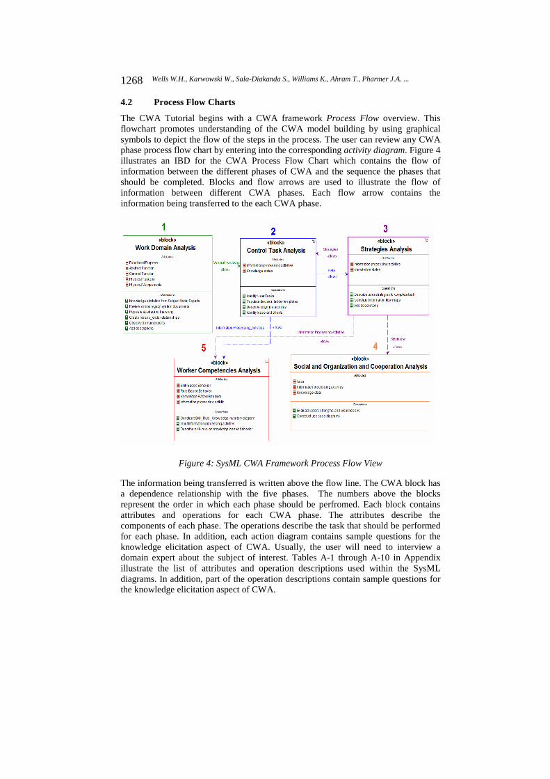
The CWA Tutorial begins with a CWA framework Process Flow overview. This flowchart promotes understanding of the CWA model building by using graphical symbols to depict the flow of the steps in the process. The user can review any CWA phase process flow chart by entering into the corresponding activity diagram. Figure 4 illustrates an IBD for the CWA Process Flow Chart which contains the flow of information between the different phases of CWA and the sequence the phases that should be completed. Blocks and flow arrows are used to illustrate the flow of information between different CWA phases. Each flow arrow contains the information being transferred to the each CWA phase.
Figure 4: SysML CWA Framework Process Flow View
The information being transferred is written above the flow line. The CWA block has a dependence relationship with the five phases. The numbers above the blocks represent the order in which each phase should be perfromed. Each block contains attributes and operations for each CWA phase. The attributes describe the components of each phase. The operations describe the task that should be performed for each phase. In addition, each action diagram contains sample questions for the knowledge elicitation aspect of CWA. Usually, the user will need to interview a domain expert about the subject of interest. Tables A-1 through A-10 in Appendix illustrate the list of attributes and operation descriptions used within the SysML diagrams. In addition, part of the operation descriptions contain sample questions for the knowledge elicitation aspect of CWA.
1268 Wells W.H., Karwowski W., Sala-Diakanda S., Williams K., Ahram T., Pharmer J.A. ...

4.3 Process Flow for Abstraction Hierarchy
The second step in the CWAT process is the construction of the Abstraction Hierarchy (AH). Figure 5 illustrates an activity diagram that shows the process of building an AH using SysML. It is composed of the initial flow symbol, action blocks, control flow arrows and final activity symbols. Within each action block, there is an explanation of which SysML menus and diagrams need to be selected to complete the models.
Figure 5: SysML CWA Abstraction Hierarchy
4.4 CWA Process Flow for Decision Ladder
The third step in CWAT process is the construction of the Decision Ladder (DL). An activity diagram shows the process for building an DL using SysML. It is composed of an initial flow symbol, action blocks, control flow arrows, and an activity final symbol. Each process flow chart step number matches a step number. Additionally, there are step-by-step instructions located within the description section of each action block on the process flow chart. Within each action block, there is also an explanation of which SysML menus and diagrams should be used to complete the models.
1269Wells W.H., Karwowski W., Sala-Diakanda S., Williams K., Ahram T., Pharmer J.A. ...

Figure 6: An Image of a Decision Ladder Constructed using SysML
4.5 Process for Constructing an Information Flow Maps
The fourth step in the CWAT process is the construction of an Information Flow Map (IFM). An activity diagram presents a process flow chart for building an IFM using SysML. The process flow chart is composed of the same diagrams used in the previous steps.
1270 Wells W.H., Karwowski W., Sala-Diakanda S., Williams K., Ahram T., Pharmer J.A. ...
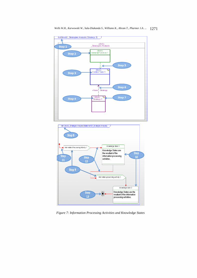
Figure 7: Information Processing Activities and Knowledge States
1271Wells W.H., Karwowski W., Sala-Diakanda S., Williams K., Ahram T., Pharmer J.A. ...

4.6 Process Flow for Constructing a Use Case
The fifth step in the CWAT is the construction of a Use Case (UC) Diagram for the Social Organization and Cooperation Analysis (SOCA) phase of CWA. Figure 8 presents an activity diagram for a process flow chart for building a UC using SysML. The process flow chart is composed of the same diagrams used in the previous steps.
Figure 8: A Process Flow Chart for Constructing a Social Organization and Cooperation Analysis Use Case using SysML
4.7 Process Flow for Constructing an S-R-K Inventory
The sixth and final step of the CWAT is the construction of a Skill-, Rule-, and Knowledge-Based (SRK) Inventory. The activity diagram that presents a process flow chart for building an SRK inventory using SysML is shown in Figure 9.
5 CWA Cognitive Factors Team
The Cognitive Factors Team section of the CWA Tutorial provides system engineers with a description of the educational background and experience that team members should have in order to effectively deploy CWA. A Cognitive Factors Team is a group of experts that study problem-solving, decision making and information processing activities in the context of human-systems integration. Table 1 describes the required knowledge and skills of team members. Table 2 illustrates the required team experience. Additionally, the UC section will inform and support system engineers in coordinating their efforts with the cognitive factors team. The UC section
1272 Wells W.H., Karwowski W., Sala-Diakanda S., Williams K., Ahram T., Pharmer J.A. ...

is composed of an actor, use cases, association relationships, and generalization relationships. The actor diagram represents the cognitive factors team.
Eduational Background Description
Human Factors Engineering
Human factors engineering is the application of knowledge about human beings physical and cognitive strengths and weaknesses to the design of systems, processes, and work environments. The objective of Human Factors Engineering is to improve human and system performance, improve ease of use, and increase user satisfaction [Wickens et al., 2004].
Human-Computer Interaction
Human–computer interaction is the study of the interactions between human users and computers. Human–computer interaction focuses on the human interaction with the computer interface.
Behavioral Psychology Behavioral psychology is the study of how human behaviors are acquired by interaction with the environment [Skinner, 1984].
Experimental Psychology Experimental psychology is an area of psychology that utilizes scientific methods to research the cognitive processes and behavior [Pashler, 2002].
Industrial & Organizational Psychology
Industrial and organizational psychology is concerned with the study of workplace behavior. The objective of industrial and organizational psychologists is to increase workplace productivity, employee selection and training programs, and system testing [Anderson et al., 2002].
Cognitive Science/Psychology
Cognitive science is the scientific study of how human perception, language, and reasoning of information are represented and transformed [Thagard, 2004].
Cognitive engineering Cognitive engineering is a field of study focused on user centered design that promotes effective human system interaction [Schraagen et al., 2000].
Cognitive ergonomics Cognitive ergonomics focuses on analyzing human cognitive processes such as decision making and planning. Cognitive ergonomic professionals develop training programs and information technology systems that support cognitive tasks. This helps to improve human performance of cognitive tasks. For example, designing of a software interface or an airplane cockpit [Vicente, 1999].
Ergonomics Ergonomics is the study of designing equipment and devices that fit the human body (i.e. body movements and cognitive abilities). Ergonomist apply theories, principles, and methods to design in order to optimize
1273Wells W.H., Karwowski W., Sala-Diakanda S., Williams K., Ahram T., Pharmer J.A. ...

human well-being and overall system performance [Stanton, 2005].
Human factors Human factors is a multidisciplinary field incorporating contributions from psychology, engineering, industrial design, statistics, operations research and anthropometry. The study of human factor focuses on the physical or cognitive property of an individual or group when interacting with a system [Stanton et al., 2005].
Table 1: Cognitive Factors: Team Educational Background Description
Figure 9: A Skill-, Rule-, and Knowledge-Based Inventory Constructed using SysML
Experience Type Description Interface Design Designing cognitively and/or perceptually-based
interfaces. Conducting Research Conducting research to develop methods of
understanding factors affecting human performance. User Centered Design Principals
An applied knowledge in a variety of human system integration tools and user centered design principals.
Experimental design Familiar with experimental design, data collection, cognitive walkthroughs and analysis.
Usability Testing Human factors engineering experience with system interface design and usability testing to determine and assess total system performance.
Table 2: Cognitive Factors: Team Experience Description
6 Conclusions The main objective of this study was to develop a cognitive work analysis (CWA) framework using the Systems Modeling Language (SysML). The CWA framework
1274 Wells W.H., Karwowski W., Sala-Diakanda S., Williams K., Ahram T., Pharmer J.A. ...
provides a structured approach for defining, managing, organizing, and modeling cognitive work requirements in systems engineering process. In the first phase, the CWA terminology was aligned with the SysML to develop a CWA framework. In the second step, a SysML-based CWA Tutorial was developed to aid systems engineers with incorporating cognitive factors into the engineering design process. The developed CWA Tutorial facilitates the identification of cognitive requirements that systems engineers can proactively use to support user performance in the context of human-systems integration. Future research will concentrate on identifying key components and interactions of cognitive factors affecting human performance in terms of cognitive work requirements and to determine total system performance.
References
[Anderson et al., 2002] Anderson, N., Deniz, S., Sinangil, H. K., and Viswesvaran, C.: "Handbook of industrial, work and organizational psychology: Personnel psychology"; Sage Pubns Ltd (2002).
[Department of the Navy, 2001] Department of the Navy: "Surface warfare program manager's guide to human systems integration"; U.S. Department of the Navy (2001).
[Hause, 2006] Hause, M.: "The SysML modeling language"; Fifteenth European Systems Engineering Conference, 9 (2006).
[Holt and Perry, 2008] Holt, J. and Perry, S.: “SysML for Systems Engineering”; The Institution for Engineering and Technology, London (2008).
[Naikar et al., 2006] Naikar, N., Moylan, A., & Pearce, B.: "Analysing activity in complex systems with cognitive work analysis: Concepts, guidelines and case study for control task analysis"; Theoretical Issues in Ergonomics Science, 7,4 (2006), 371-394.
[OMG, 2011] OMG Systems Modeling Language, 2011, http://sysml-directory.omg.org/
[Pashler, 2002] Pashler, H. E.: "Steven's handbook of experimental psychology: Sensation and perception (3rd ed.)" Wiley, New York (2002)
[Rasmussen et al., 1990] Rasmussen, J., Pejtersen, A. M., & Schmidt, K.: "Taxonomy for cognitive work analysis", Roskilde, Denmark: Risoe National Laboratory (1990).
[Schraagen et al., 2000] Schraagen, J.M., Chipman, S.F., & Shalin, V.L. (Eds.). Cognitive task analysis. Mahwah, NJ: Lawrence Erlbaum Associates (2000)..
[Skinner, 1984] Skinner, B. F.: "The operational analysis of psychological terms"; Behavioral and Brain Sciences, 7,04 (1984), 547-553.
[Stanton, 2005] Stanton, N.: "Handbook of human factors and ergonomics methods”; CRC Press, Boca Raton (2005).
[Stanton et al., 2005] Stanton, N., Salmon, P., Walker, G., Baber, C., & Jenkins, D.: "Human factors methods: A practical guide for engineering and design"; CRC Press, Boca Raton ( 2005).
[Stoner et al., 2006] Stoner, H. A., Stelzer, E. M., Wiese, E. E., Paley, M., Darowski, A., Mizrahi, G., & Martin, E. A.: "The resource for applied cognitive and systems engineering (trace-se): An approach to understanding the gap"; Human Factors and Ergonomics Society Annual Meeting Proceedings, 50,17 (2006),1872-1876.
[Thagard, 2004] Thagard, P.: "Cognitive science"; Stanford Encyclopedia of Philosophy (2004).
1275Wells W.H., Karwowski W., Sala-Diakanda S., Williams K., Ahram T., Pharmer J.A. ...
[Vicente, 1999] Vicente, K. J.: "Cognitive work analysis: Toward safe, productive, and healthy computer-based work"; Lawrence Erlbaum Associates, Mahwah, N.J. (1999).
[Wickens et al., 2004] Wickens, C. D., Gordon, S. E., & Liu, Y.: "An introduction to human factors engineering"; Pearson Prentice Hall (2004).
Appendix
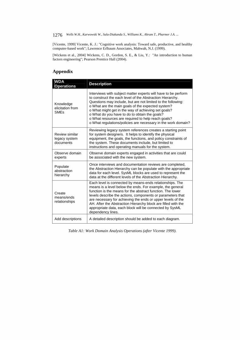
WDA Operations Description
Knowledge elicitation from SMEs
Interviews with subject matter experts will have to be perform to construct the each level of the Abstraction Hierarchy. Questions may include, but are not limited to the following: o What are the main goals of the expected system? o What might get in the way of achieving set goals? o What do you have to do to obtain the goals? o What resources are required to help reach goals? o What regulations/policies are necessary in the work domain?
Review similar legacy system documents
Reviewing legacy system references creates a starting point for system designers. It helps to identify the physical equipment, the goals, the functions, and policy constraints of the system. These documents include, but limited to instructions and operating manuals for the system.
Observe domain experts
Observe domain experts engaged in activities that are could be associated with the new system.
Populate abstraction hierarchy
Once interviews and documentation reviews are completed, the Abstraction Hierarchy can be populate with the appropriate data for each level. SysML blocks are used to represent the data at the different levels of the Abstraction Hierarchy.
Create means/ends relationships
Each level is connected by means-ends relationships. The means is a level below the ends. For example, the general function is the means for the abstract function. The lower levels describe the actions, components or parameters that are necessary for achieving the ends or upper levels of the AH. After the Abstraction Hierarchy block are filled with the appropriate data, each block will be connected by SysML dependency lines.
Add descriptions A detailed description should be added to each diagram.
Table A1: Work Domain Analysis Operations (after Vicente 1999).
1276 Wells W.H., Karwowski W., Sala-Diakanda S., Williams K., Ahram T., Pharmer J.A. ...

WDA Attributes Description Functional Purpose The functional purpose describes the reasons the system exist.
Abstract Function
The abstract function level describes the performance parameters required for the system to meet its intended purpose.
General Function
The general function level describes the basic work functions of the system.
Physical Function
The physical function defines the equipment, tools, resources and/or physical objects available for the system.
Physical Components
The physical component level describes the sub-components of the equipment, tools, resources and/or physical objects available for the system.
Table A2: Work Domain Analysis Attributes (after Vicente 1999).
ConTA Operations Description
Identify user tasks
Use interviews and other knowledge elicitation methods with subject matter experts to construct the each level of the Decision Ladder. The most common knowledge elicitation method is directly questioning domain experts on how they conduct their jobs and the tasks necessary to successfully complete their jobs. An example question may include, but not limited to the following: o What are some of the steps taken to achieve a task? o What kinds of events can act as alerts? o What kinds of data or facts is available? o What kinds of assessments about the system’s condition or situation is possible with the information? o What kinds of choices or alternatives are available for the system’s desired or target state? o What kinds of aims or objectives can be relevant or influence decisions? o What kinds of target states are possible? o What kinds of tasks are necessary and what kinds of resources are available? o What kinds of procedures or sequences of steps are necessary?
Describe cognitive activities
Interview domain experts to describe cognitive activities required to complete a system task.
Identify leaps and shunts
During subject matter experts interviews, identify shortcuts experts would use when completing a task.
Populate decision ladder templates
Once interviews are completed, the Decision Ladder can be populated with the appropriate data for each step on the ladder. Use SysML state machine diagrams. "Send Action" and "State" diagrams are used to represent the information processing activities and knowledge states at the different steps in the Decision Ladder.
1277Wells W.H., Karwowski W., Sala-Diakanda S., Williams K., Ahram T., Pharmer J.A. ...

ConTA Operations Description
Add descriptions A detailed description should be added to each diagram.
Table A-3: Control Task Analysis Operations (after Vicente 1999).
ConTA Attributes Description Information processing activities
Information processing activities are the mental or cognitive activities system operators must utilize to complete a task.
Knowledge states
States of knowledge is the result of an information processing activities.
Table A-4: Control Task Analysis Attributes (after Vicente 1999).
SA Operations Description
Describe user strategies to complete task
Use interviews and other knowledge elicitation methods with subject matter experts to construct each level of the Decision Ladder. The most common knowledge elicitation method is directly questioning domain experts on the course of action used to complete a task. Questions may include, but not limited to the following: o What are some of the possible strategies that can use to complete a task? o Which of the strategies mentioned before would most system operators use to complete a task? o What steps would a system novice use to complete a task? o What steps would a system expert use to complete a task?
Construct Information flow maps
Use data collected during interviews to construct information flow maps. Use SysML state machine diagrams. "Send Action" and "State" diagrams are used to represent the information processing activities and knowledge states respectively.
Add descriptions A detailed description should be added to each diagram.
Table A-5: Strategies Analysis Operations (after Vicente 1999).
SA Attributes Description
Information processing activities
Information processing activities are the mental or cognitive activities system operators must utilize to complete a task.
Knowledge states
States of knowledge is the result of an information processing activities.
Table A-6: Strategies Analysis Attributes (after Vicente 1999).
1278 Wells W.H., Karwowski W., Sala-Diakanda S., Williams K., Ahram T., Pharmer J.A. ...

SOCA Operations Description
Evaluate actors’ strengths and weaknesses
Use interviews and other knowledge elicitation methods with subject matter experts to identify actors and assign task responsibilities. The most common knowledge elicitation method is direct questioning domain experts who will do what tasks. The tasks are the result of the Strategies analysis phase. Questions may include, but not limited to the following: o Describe the various teams using the system? o How do you allocate responsibilities for each person? o Who depends on whom for help to complete a task? o What is the specific role of each team member? o How decisions are usually made?
Construct use case diagrams
Use data collected during interviews and information processing activities and knowledge states from the Strategies Analysis phase to construct use case diagrams. Use SysML use case diagrams. "Actors" and "Use case" diagrams are used to represent the system users, information processing activities, and knowledge states.
Table A-7: Social Organization and Cooperation Analysis Operations (after Vicente 1999).
SOCA Attributes Description Information Processing Activities
Information processing activities are the mental or cognitive activities system operators must utilize to complete a task.
Knowledge States
States of knowledge is the result of an information processing activities.
Actors Specifies a role played by a person or thing when interacting with a system.
Table A-8: Social Organization and Cooperation Analysis Attributes (after Vicente 1999).
WCA Operations Description
Describe skill-, rule-, or knowledge-based behavior
Use interviews and other knowledge elicitation methods with subject matter experts to identify the level of knowledge required by the user to complete an information processing activities. The most common knowledge elicitation method is direct questioning of domain experts. The information processing activities are the result of the Control Task Analysis and Strategies Analysis phase. Questions may include, but limited to the following: o What information the user have to know in order to complete the information processing activities? o What rules, regulations, or policies does the user need to
1279Wells W.H., Karwowski W., Sala-Diakanda S., Williams K., Ahram T., Pharmer J.A. ...

WCA Operations Description
know? o What problem solving procedures will the user have to be familiar with?
Construct Skill, Rule Knowledge inventory diagram
The information processing activities come from the Control Task Analysis and Strategies Analysis phases.
Information processing activities input
Use data collected during interviews and information processing activities from the Control Task Analysis and Strategies Analysis phase to construct Skill, Rule and Knowledge Inventory diagram. Use SysML "swimlanes", "send action" diagrams and "action" diagrams to represent the level of cognitive behavior (i.e. Skill-Based Behavior (SBB), Rule-Based Behavior (RBB), Knowledge-Based Behavior (KBB)), information processing activities from the Control Task Analysis and Strategies Analysis phase, and level of knowledge required by the user, respectively.
Table A-9: Worker Competencies Analysis Operations (after Vicente 1999).
WCA Attributes Description
Skill-Based Behavior (SBB)
A skill-based behavior requires very little conscious effort to perform a task. Using a mouse to move a cursor is an example of a skill-based behavior.
Rule-Based Behavior (RBB)
A rule-based behavior is based on the rules and/or procedures established by an organization. For example, user instructions or regulatory authority rules necessary to complete a task or use equipment.
Knowledge-Based Behavior (KBB)
A knowledge-based behavior requires the highest level of conscious effort to complete a task. An example of a knowledge-based behavior is a pilot response to losing both engines due to bird strikes and landing the airplane in the Hudson River.
Information processing activity
Information processing activities are the mental or cognitive activities system operators must utilize to complete a task.
Table A-10: Workers' Competencies Analysis Attributes (after Vicente 1999).
1280 Wells W.H., Karwowski W., Sala-Diakanda S., Williams K., Ahram T., Pharmer J.A. ...