Application of radar and pulse echo for testing concrete ... of Radar and Ultrasonic Pulse Echo for...
6
NDTCE’09, Non-Destructive Testing in Civil Engineering Nantes, France, June 30th – July 3rd, 2009 Application of Radar and Ultrasonic Pulse Echo for Testing Concrete Structures Srinivasan PARTHASARATHY 1 , S.G.N. MURTHY 1 , Bhaskar,SANGOJU 1 , Herbert WIGGENHAUSER 2 , Kapali RAVISANKAR 1 , Nagesh R. IYER 1* and Narayanan LAKSHMANAN 1@ 1 Scientist, 1* Director, 1@ Formerly Director; Structural Engineering Research Centre, CSIR, Chennai, India, (Corresponding author e-mail: [email protected] ) 2 Head of Division VIII.2, BAM, Berlin, Germany. Abstract Nondestructive testing of concrete structures is one of the essential task for estimating or assessing the quality. In order to validate the advanced NDT equipments like Radar and Pulse Echo, a unique large scale reinforced concrete specimen was cast at SERC, Chennai, with columns and beams of different sizes, cross section having different percentages of reinforcement. The defects such as honeycombs, cracks, delamination, presence of conduits, ducts, etc. were also incorporated while casting the large scale reinforced cement concrete specimen. In the present study, the top and bottom slabs were investigated by dividing into grid lines of 50 x 50 mm in both the direction using radar and pulse echo techniques. For radar measurements, 1.6 GHz antenna was used over the grid lines. The pulse echo technique was adopted with an antenna array of 55 KHz and the data was collected over the same grid points. Two different data analysis programs were used for the analysis of the data. This paper highlights the test results from the application of these two methods Radar and Pulse Echo on the concrete slabs. The need for automatic scanning for both the methods compared to manual measurement is highlighted. The advantages and the limitations of the test methods are also discussed with respect to this specimen. Résumé L'essai non destructif de structures de béton est l'une des tâches essentielles à effectuer pour estimer ou évaluer la qualité. Afin de valider les équipements avancés pour les essais non destructifs comme le radar et la méthode par pulse-écho, un spécimen unique en béton armé à grande échelle a été coulé au CRCC, à Chennai, avec des colonnes et des poutres de tailles différentes et des coupes ayant différents pourcentages d'armature. Les défauts tels que les nids d'abeilles, les fissures, le délaminage, la présence de canalisations et de conduits, etc. ont également été incorporés lors du coulage du spécimen en béton armé à grande échelle. Dans la présente étude, les blocs du haut et du bas ont été examinés en divisant en un quadrillage de 50 par 50 mm dans les deux directions, et en utilisant le radar et la méthode par pulse-écho. Pour les mesures du radar, une antenne de 1,6 GHz a été utilisée sur le quadrillage. La méthode par pulse-écho a été adoptée avec un réseau d'antennes de 55 KHz et les données ont été recueillies sur le même quadrillage. Deux différents programmes d'analyse de données ont été utilisés pour l'analyse des données. Cette communication met en avant les résultats des essais issus de l'application de ces deux méthodes par radar et par pulse-écho sur les blocs de béton. La nécessité d'un balayage automatique pour les deux méthodes, en comparaison avec une mesure manuelle, est soulignée. Les avantages et les limites des méthodes d'essai sont aussi examinés en rapport avec ce corps d’épreuve. Keywords Non-destructive testing, Radar, Ultrasonic Pulse echo, Concrete, Defects
-
Upload
truongliem -
Category
Documents
-
view
220 -
download
1
Transcript of Application of radar and pulse echo for testing concrete ... of Radar and Ultrasonic Pulse Echo for...

NDTCE’09, Non-Destructive Testing in Civil Engineering Nantes, France, June 30th – July 3rd, 2009
Application of Radar and Ultrasonic Pulse Echo for Testing Concrete Structures Srinivasan PARTHASARATHY1, S.G.N. MURTHY1, Bhaskar,SANGOJU 1, Herbert WIGGENHAUSER2, Kapali RAVISANKAR1, Nagesh R. IYER1* and Narayanan LAKSHMANAN1@
1 Scientist, 1* Director, 1@ Formerly Director; Structural Engineering Research Centre, CSIR, Chennai, India, (Corresponding author e-mail: [email protected]) 2 Head of Division VIII.2, BAM, Berlin, Germany. Abstract Nondestructive testing of concrete structures is one of the essential task for estimating or assessing the quality. In order to validate the advanced NDT equipments like Radar and Pulse Echo, a unique large scale reinforced concrete specimen was cast at SERC, Chennai, with columns and beams of different sizes, cross section having different percentages of reinforcement. The defects such as honeycombs, cracks, delamination, presence of conduits, ducts, etc. were also incorporated while casting the large scale reinforced cement concrete specimen. In the present study, the top and bottom slabs were investigated by dividing into grid lines of 50 x 50 mm in both the direction using radar and pulse echo techniques. For radar measurements, 1.6 GHz antenna was used over the grid lines. The pulse echo technique was adopted with an antenna array of 55 KHz and the data was collected over the same grid points. Two different data analysis programs were used for the analysis of the data. This paper highlights the test results from the application of these two methods Radar and Pulse Echo on the concrete slabs. The need for automatic scanning for both the methods compared to manual measurement is highlighted. The advantages and the limitations of the test methods are also discussed with respect to this specimen.
Résumé L'essai non destructif de structures de béton est l'une des tâches essentielles à effectuer pour estimer ou évaluer la qualité. Afin de valider les équipements avancés pour les essais non destructifs comme le radar et la méthode par pulse-écho, un spécimen unique en béton armé à grande échelle a été coulé au CRCC, à Chennai, avec des colonnes et des poutres de tailles différentes et des coupes ayant différents pourcentages d'armature. Les défauts tels que les nids d'abeilles, les fissures, le délaminage, la présence de canalisations et de conduits, etc. ont également été incorporés lors du coulage du spécimen en béton armé à grande échelle. Dans la présente étude, les blocs du haut et du bas ont été examinés en divisant en un quadrillage de 50 par 50 mm dans les deux directions, et en utilisant le radar et la méthode par pulse-écho. Pour les mesures du radar, une antenne de 1,6 GHz a été utilisée sur le quadrillage. La méthode par pulse-écho a été adoptée avec un réseau d'antennes de 55 KHz et les données ont été recueillies sur le même quadrillage. Deux différents programmes d'analyse de données ont été utilisés pour l'analyse des données. Cette communication met en avant les résultats des essais issus de l'application de ces deux méthodes par radar et par pulse-écho sur les blocs de béton. La nécessité d'un balayage automatique pour les deux méthodes, en comparaison avec une mesure manuelle, est soulignée. Les avantages et les limites des méthodes d'essai sont aussi examinés en rapport avec ce corps d’épreuve.
Keywords Non-destructive testing, Radar, Ultrasonic Pulse echo, Concrete, Defects
NDTCE’09, Non-Destructive Testing in Civil Engineering Nantes, France, June 30th – July 3rd, 2009
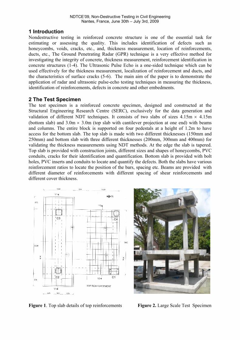
1 Introduction Nondestructive testing in reinforced concrete structure is one of the essential task for estimating or assessing the quality. This includes identification of defects such as honeycombs, voids, cracks, etc., and, thickness measurement, location of reinforcements, ducts, etc., The Ground Penetrating Radar (GPR) technique is a very effective method for investigating the integrity of concrete, thickness measurement, reinforcement identification in concrete structures (1-4). The Ultrasonic Pulse Echo is a one-sided technique which can be used effectively for the thickness measurement, localization of reinforcement and ducts, and the characteristics of surface cracks (5-6). The main aim of the paper is to demonstrate the application of radar and ultrasonic pulse-echo testing techniques in measuring the thickness, identification of reinforcements, defects in concrete and other embedments. 2 The Test Specimen The test specimen is a reinforced concrete specimen, designed and constructed at the Structural Engineering Research Centre (SERC), exclusively for the data generation and validation of different NDT techniques. It consists of two slabs of sizes 4.15m × 4.15m (bottom slab) and 3.0m × 3.0m (top slab with cantilever projection at one end) with beams and columns. The entire block is supported on four pedestals at a height of 1.2m to have access for the bottom slab. The top slab is made with two different thicknesses (150mm and 250mm) and bottom slab with three different thicknesses (200mm, 300mm and 400mm) for validating the thickness measurements using NDT methods. At the edge the slab is tapered. Top slab is provided with construction joints, different sizes and shapes of honeycombs, PVC conduits, cracks for their identification and quantification. Bottom slab is provided with bolt holes, PVC inserts and conduits to locate and quantify the defects. Both the slabs have various reinforcement ratios to locate the position of the bars, spacing etc. Beams are provided with different diameter of reinforcements with different spacing of shear reinforcements and different cover thickness.
C1C2
C3 C4
Figure 1. Top slab details of top reinforcements Figure 2. Large Scale Test Specimen

NDTCE’09, Non-Destructive Testing in Civil Engineering Nantes, France, June 30th – July 3rd, 2009
Beams are provided with ducts to study the grouting problems in prestressing ducts. Columns are provided with different diameter of reinforcements with different spacing of lateral ties and different cover thicknesses. Different grades of concrete are used in casting the beams, columns and slabs. The details of the reinforcement of the top slab are given in Figs.1. Fig. 2 shows the completed large scale test specimen. Fig. 3 shows the details of the defects namely honeycomb concrete, PVC pipe, steel plate, steel box and cracked concrete specimen containing reinforcement in the top slab.
Figure. 3 Top slab details of honeycombs, PVC pipes and steel embedments
3 Radar measurements For the radar measurements, SIR-20 model of GSSI has been used with 1.60 GHz antenna. This frequency was chosen for a maximum penetration depth of 500 mm. For data collection the bottom slab was divided into grids of size 50 mm x 50 mm. A portion of 2.0 m x 2.0 m within the beams was considered for scanning. The data was collected from the top face on the bottom slab. Fig. 4 shows the measurement on the bottom slab. The upper portion of Fig. 5 shows the raw data of the radargram for the bottom slab. The lower portion of Fig.5 shows the dataset after correcting for the surface reflection to time zero and also the migration.
Rebars
SERC NDT SPECIMEN
Figure 4. Measurement with 1.6 GHz antenna Figure 5. Reinforcements before and after
Migration

NDTCE’09, Non-Destructive Testing in Civil Engineering Nantes, France, June 30th – July 3rd, 2009
The radar wave velocity in the medium between the surface and the target determines the shape of a hyperbolic reflection. The Migration function calculates the signal velocity in the medium from the shape of hyperbolic reflections . Migration eliminates hyperbolas by collapsing them into dots representing the actual targets. The data which was collected in both the directions were processed using the RADAN software supplied by GSSI, USA and the 3-D animation view was obtained. Fig.6 shows the reinforcements present in the bottom slab. The spacing of the reinforcements obtained in the line scan was matching with the actual dimensions. The reinforcements are found to be distorted in the C-scan and this is due to the manual collection of the data. The sloping portion of the bottom slab, i.e., the back wall reflection was obtained and is shown in Fig. 7.
Figure 6 . Reinforcements in Bottom slab- Figure.7 Radargram in sloping portion of C- scan bottom slab The top slab was also divided into grids of 50 x 50 mm over an area of 2.0 m x 2.0 m between the beams. The radar data was collected on the top and bottom side of the slab. The data was processed using RADAN software. Fig. 8 shows the C-scan which gives the reinforcement obtained after processing. The absence of top reinforcements in the centre portion of Fig. 8 is comparable to that shown in Fig. 1. The presence of steel box and the PVC pipe is shown in Fig. 9.
Figure 8. C-scan at 45 mm from top face Figure 9. C-scan at 70 mm from top face
NDTCE’09, Non-Destructive Testing in Civil Engineering Nantes, France, June 30th – July 3rd, 2009
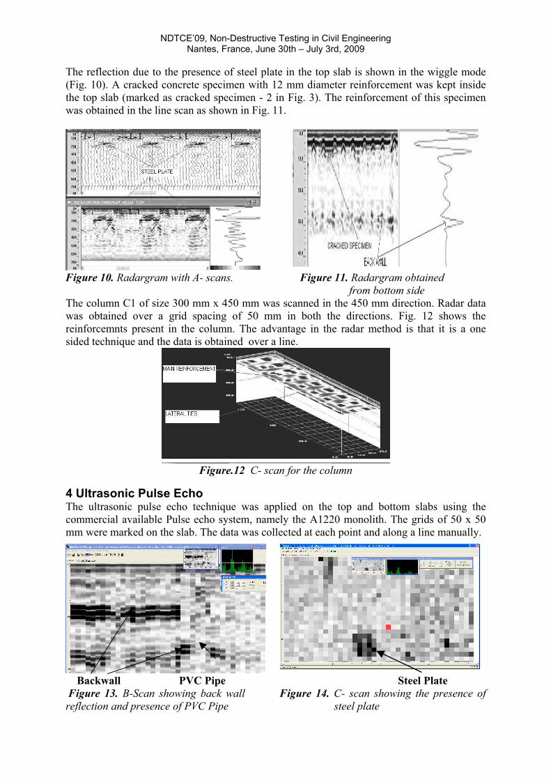
The reflection due to the presence of steel plate in the top slab is shown in the wiggle mode (Fig. 10). A cracked concrete specimen with 12 mm diameter reinforcement was kept inside the top slab (marked as cracked specimen - 2 in Fig. 3). The reinforcement of this specimen was obtained in the line scan as shown in Fig. 11.
Figure 10. Radargram with A- scans. Figure 11. Radargram obtained from bottom side The column C1 of size 300 mm x 450 mm was scanned in the 450 mm direction. Radar data was obtained over a grid spacing of 50 mm in both the directions. Fig. 12 shows the reinforcemnts present in the column. The advantage in the radar method is that it is a one sided technique and the data is obtained over a line.
Figure.12 C- scan for the column
4 Ultrasonic Pulse Echo The ultrasonic pulse echo technique was applied on the top and bottom slabs using the commercial available Pulse echo system, namely the A1220 monolith. The grids of 50 x 50 mm were marked on the slab. The data was collected at each point and along a line manually.
Backwall PVC Pipe Steel Plate Figure 13. B-Scan showing back wall Figure 14. C- scan showing the presence of reflection and presence of PVC Pipe steel plate

NDTCE’09, Non-Destructive Testing in Civil Engineering Nantes, France, June 30th – July 3rd, 2009
The A-scan and B-scans are obtained in the instrument After collecting, the data was transferred to a computer and analysed using the post processing software. Fig. 13 shows the back wall reflection and the thickness of the slab are found to be 150 and 250 mm. The presence of steel plate is shown in Fig. 14.In the pulse echo method, the measurements are found to be time consuming since it is a point based measurement. Also the effect of contact of the transducers on the concrete surface assumes importance. Hence the automatic scanning and data processing software will be better for data collection. This will also reduce the time and the accuracy will also be improved. The advantage is that it is a one sided technique. In this method the reinforcement identification is not possible. 5 Conclusions The application of radar and pulse echo have been demonstrated for the thickness measurement, identification of reinforcements, steel embedment, and honeycombs. The need for automatic scanning for data collection vs manual collection of data on a large scale structure for both the radar and also for the pulse echo is highlighted. The B-scans and C-scans as obtained for the radar measurements gives the reinforcement distribution. The depth slice also provide useful information in identifying the steel embedment and the PVC conduits. For the radar measurements it was observed that the spacing of the reinforcement affects the penetration of the waves in to the concrete. The ultrasonic pulse echo technique provide information on the exact thickness of the concrete member. In addition, the embedments such as steel plate or PVC pipe can be identified. However the presence of reinforcements cannot be identified. Additional research is required for the effect of spacing and the size of the reinforcement on the penetration of radar waves in concrete.
Acknowledgements The above mentioned work is a part of the activities carried out at SERC during the visit of Prof. Wiggenhauesr, BAM, Germany under the CSIR- Humboldt Fellowship programme. The assistance rendered by the project students Mr. B.A.R.Chakravarthy and S.Dinesh are also acknowledged. The paper is being published with the kind permission of The Director, SERC, Chennai.
References 1. Krause M, Maierhofer C, Wiggenhauser H. (1995), “Thickness measurement of concrete
elements using radar and ultrasonic impulse echo techniques”, 6th International conference on structural faults and repair, Edited by Forde MC, 1997, London, UK, vol. 1, pp. 17–24.
2. Maierhofer C. (2003) “Nondestructive Evaluation of Concrete Infrastructure with Ground Penetrating Radar”, Journal of Materials In Civil Engineering, ASCE, May-June 2003, PP. 287-297.
3. Hevin G, Abraham O, Pedersen HA, Campillo M.(1998), “ Characterization of surface cracks with Rayleigh waves: a numerical model”, Nondestructive testing and evaluation international, 31,1998, pp. 289–97
4. Johannes Hugenschmidit, Roman Mastrangelo. (2006) “GPR inspection of concrete bridges”, Cement & Concrete Composites, 28 , 2006, pp. 384-392.
5. Krause M, Ba¨rmann R, Friedlinghaus R, Kretzschamar F, Kroggel O, Langenberg K, Maierhofer Ch, Mu¨ ller W, Neisecke J, Schickert M, Schmitz V, Wiggenhauser H, Wollbold F. (1997), Comparison of pulse echo methods for testing concrete’ NDT& E International 4 (special issue), 1997, pp. 195–204.
6. Christoph Kohl, Doreen Streicher,(2006) “Results of reconstructed and fused NDT-data measured in the laboratory and on-site at bridges”, Cement & Concrete Composites, 2006, pp.402-413.