APPLICATION OF NON-DETERMINISTIC METHODS TO …mln/ltrs-pdfs/NASA-2004-8lsdyna-khl.pdf · 8th...
11
8 th International LS-DYNA Users Conference Session # 1-1 APPLICATION OF NON-DETERMINISTIC METHODS TO ASSESS MODELLING UNCERTAINTIES FOR REINFORCED CARBON-CARBON DEBRIS IMPACTS K. Lyle NASA Langley Research Center, Hampton VA E. Fasanella ARL-VTD Langley Research Center, Hampton VA M. Melis and K. Carney NASA Glenn Research Center, Cleveland OH J. Gabrys The Boeing Company, Philadelphia PA Abstract The Space Shuttle Columbia Accident Investigation Board (CAIB) made several recommendations for improving the NASA Space Shuttle Program. An extensive experimental and analytical program has been developed to address two recommendations related to structural impact analysis. The objective of the present work is to demonstrate the application of probabilistic analysis to assess the effect of uncertainties on debris impacts on Space Shuttle Reinforced Carbon-Carbon (RCC) panels. The probabilistic analysis is used to identify the material modeling parameters controlling the uncertainty. A comparison of the finite element results with limited experimental data provided confidence that the simulations were adequately representing the global response of the material. Five input parameters were identified as significantly controlling the response. Introduction The Space Shuttle Columbia Accident Investigation Board (CAIB) made several recommendations for improving the NASA Space Shuttle Program in Volume I of the final report, Ref. [1]. Two recommendations directly related to structural impact analysis are: • Initiate a program designed to increase the Orbiter’s ability to sustain minor debris damage by measures such as improved impact-resistant Reinforced Carbon-Carbon and acreage tiles. This program should determine the actual impact resistance of current materials and the effect of likely debris strikes. • Develop, validate, and maintain physics-based computer models to evaluate Thermal Protection System damage from debris impacts. These tools should provide realistic and timely estimates of any impact damage from possible debris from any source that may ultimately impact the Orbiter. Establish impact damage thresholds that trigger responsive corrective action, such as on-orbit inspection and repair, when indicated. An extensive experimental and analytical program has been developed to address these recommendations. Specifically, a multi-center analysis team has been formed to: 1) use physics-
Transcript of APPLICATION OF NON-DETERMINISTIC METHODS TO …mln/ltrs-pdfs/NASA-2004-8lsdyna-khl.pdf · 8th...
8th International LS-DYNA Users Conference Session #
1-1
APPLICATION OF NON-DETERMINISTIC METHODSTO ASSESS MODELLING UNCERTAINTIES FOR
REINFORCED CARBON-CARBON DEBRIS IMPACTS
K. LyleNASA Langley Research Center, Hampton VA
E. FasanellaARL-VTD Langley Research Center, Hampton VA
M. Melis and K. CarneyNASA Glenn Research Center, Cleveland OH
J. GabrysThe Boeing Company, Philadelphia PA
AbstractThe Space Shuttle Columbia Accident Investigation Board (CAIB) made several
recommendations for improving the NASA Space Shuttle Program. An extensive experimentaland analytical program has been developed to address two recommendations related tostructural impact analysis. The objective of the present work is to demonstrate the application ofprobabilistic analysis to assess the effect of uncertainties on debris impacts on Space ShuttleReinforced Carbon-Carbon (RCC) panels. The probabilistic analysis is used to identify thematerial modeling parameters controlling the uncertainty. A comparison of the finite elementresults with limited experimental data provided confidence that the simulations were adequatelyrepresenting the global response of the material. Five input parameters were identified assignificantly controlling the response.
IntroductionThe Space Shuttle Columbia Accident Investigation Board (CAIB) made several
recommendations for improving the NASA Space Shuttle Program in Volume I of the finalreport, Ref. [1]. Two recommendations directly related to structural impact analysis are:
• Initiate a program designed to increase the Orbiter’s ability to sustain minordebris damage by measures such as improved impact-resistant ReinforcedCarbon-Carbon and acreage tiles. This program should determine the actualimpact resistance of current materials and the effect of likely debris strikes.
• Develop, validate, and maintain physics-based computer models to evaluateThermal Protection System damage from debris impacts. These tools shouldprovide realistic and timely estimates of any impact damage from possible debrisfrom any source that may ultimately impact the Orbiter. Establish impact damagethresholds that trigger responsive corrective action, such as on-orbit inspectionand repair, when indicated.
An extensive experimental and analytical program has been developed to address theserecommendations. Specifically, a multi-center analysis team has been formed to: 1) use physics-
Session # 8th International LS-DYNA Users Conference
1-2
based state-of-the-art codes to simulate debris impacting the Shuttle Thermal Protection System(TPS); 2) validate modeling approaches through test-analysis correlation; and 3) utilize validatedmodeling approaches to assist in investigating issues not possible to test, (e.g., performingparameter studies, simulating additional scenarios, and establishing worst case scenarios). Anoverview of the team’s activities to date is documented in Ref. [2]. Related large-scalesimulations are presented in Refs. [3, 4].
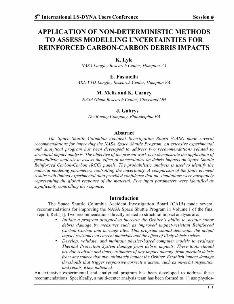
The NASA Space Shuttle leading edge is fabricated from reinforced carbon-carbon(RCC) material. The fabrication process is very complex, and the details are provided in Ref. [5].To begin fabrication, a precursor woven fabric is layered such that all plies are either in the 0 or90 degree direction. During the processing, silica is infused in the outer 2-to-3 laminae, and theresulting laminate is heated to form a silicon-carbide coating, see Figure 1. This silicon-carbidecoating is necessary to provide protection to the Space Shuttle’s leading edge during the highheating experienced on re-entry of the shuttle through the Earth’s atmosphere. As shown inFigure 1, the RCC laminate contains many voids. In addition, the process used to create thesilicon-carbide causes numerous micro-cracks in the silicon-carbide coating. The porosity andthe coating cracks result in a material with a highly complex stress-strain and failure behavior.
An extensive test program begun in the 1970’s generated data used to design the TPS.This information was revised and published in Ref. [6]. As part of the shuttle design process,several tests were performed to establish the effective material properties of the RCC laminatematerial. The effective laminate properties are dependent on several factors including whetherthe material is as-fabricated or has a degraded strength due to mass-loss heating. The data arealso affected by the relative thickness of the silicon-carbide coating and the carbon-carbonsubstrate.
Silicon-Carbide
Porosity
Figure 1. Micro-graph cross-section of 19-ply RCC material.
The objective of the present work is to demonstrate the application of probabilisticanalysis to assess the effect of various uncertainties on debris impacts on Space Shuttle RCCpanels. For general impact dynamics applications, factors affecting modeling and experimentaluncertainty include: off-nominal impact conditions (e.g., attitude and velocity); material propertyvariations (e.g., stress-strain relationships, failure modes, rate dependencies); and fabricationanomalies (e.g., non-uniform cross-sections, imperfect structural assembly). Many papersconcerning probabilistic analysis for aerospace applications exist in the literature, for examplesee Refs [7,8]. Although extensive work has been done to enable the use of probabilisticanalysis, few applications involve impact dynamics of aerospace structures. Preliminary work
8th International LS-DYNA Users Conference Session #
1-3
utilizing probabilistic analysis to bound modeling uncertainty and design optimization foraircraft crashworthiness has been documented in Refs. [9,10].
Historical data has shown that RCC material is somewhat brittle and that the stress-strainrelationship is uncertain. Therefore, probabilistic analysis will be used to identify the materialmodeling parameters controlling the response uncertainty. For the purposes of thisdemonstration, the simulations replicate beam testing performed in support of the ColumbiaAccident Investigation. The results for the simple model presented here can provide insight forassessing the uncertainty for more complex structures, such as the space shuttle wing leading-edge panels.
Description of ExperimentVirtually no data existed concerning the response of RCC material to a foam impact. Thus,
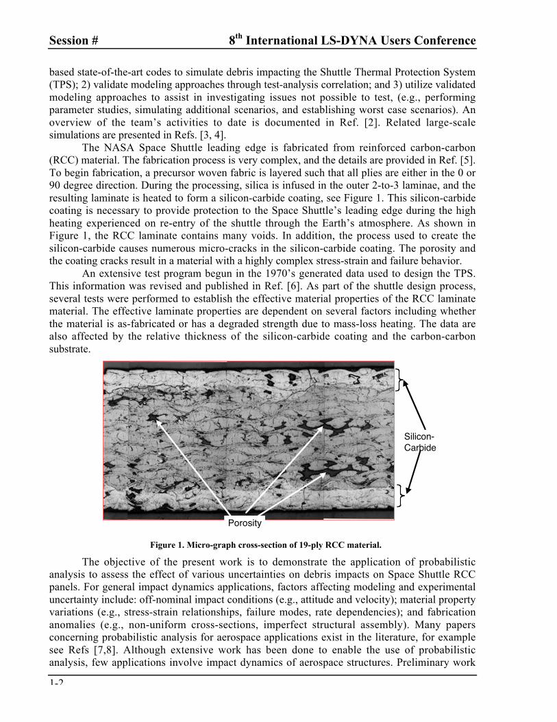
tests were performed to provide preliminary data about the response of RCC panels to impactsby external tank foam. The tests were performed at NASA Glenn Research Center at the BallisticTest Facility. A photograph of the test set-up is shown in Figure 2. Details about the operation ofthe facility can be found in Ref. [11]. For these tests, cylindrical foam projectiles impacted 1.5-inx 6-in., 19-ply RCC beam specimens at velocities ranging from 397 to 695 ft/s. The beams weresimply-supported 0.5-in. from each end. The foam projectile was 1.25-in. in diameter and 3-in.long. Beam deflections and constraint loads were measured and recorded at a 50 kHz samplerate.
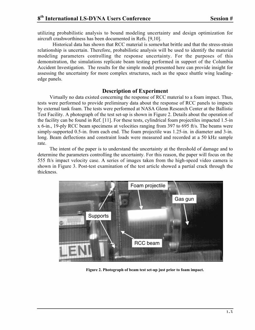
The intent of the paper is to understand the uncertainty at the threshold of damage and todetermine the parameters controlling the uncertainty. For this reason, the paper will focus on the555 ft/s impact velocity case. A series of images taken from the high-speed video camera isshown in Figure 3. Post-test examination of the test article showed a partial crack through thethickness.
Foam projectile
RCC beam
Supports
Gas gun
Figure 2. Photograph of beam test set-up just prior to foam impact.
Session # 8th International LS-DYNA Users Conference
1-4
Figure 3. Series of photographs showing panel impacted by foam cylinder.
Description of Finite Element ModelTo make this study possible, the finite element model was developed with three
requirements in mind. The model and simulations must be computationally efficient, stable, andcapable of capturing the basic physics of the desired structural response. Computationalefficiency is necessary to enable completion of the numerous simulations. The simulations mustbe stable over the span of input parameters to avoid non-physical or non-feasible responses.Finally, the simulations must capture the basic physics concerning the RCC response to impactloading near the threshold of damage.
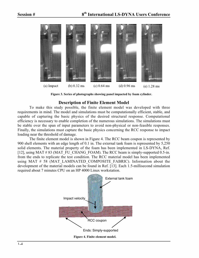
The finite element model is shown in Figure 4. The RCC beam coupon is represented by900 shell elements with an edge length of 0.1 in. The external tank foam is represented by 5,250solid elements. The material property of the foam has been implemented in LS-DYNA, Ref.[12], using MAT # 83 (MAT_FU_CHANG_FOAM). The RCC beam is simply-supported 0.5-in.from the ends to replicate the test condition. The RCC material model has been implementedusing MAT # 58 (MAT_LAMINATED_COMPOSITE_FABRIC). Information about thedevelopment of the material models can be found in Ref. [13]. Each 1.5-millisecond simulationrequired about 7 minutes CPU on an HP 4000 Linux workstation.
External tank foam
RCC coupon
Impact velocity
Ends: Simply-supported
Figure 4. Finite element model.
8th International LS-DYNA Users Conference Session #
1-5
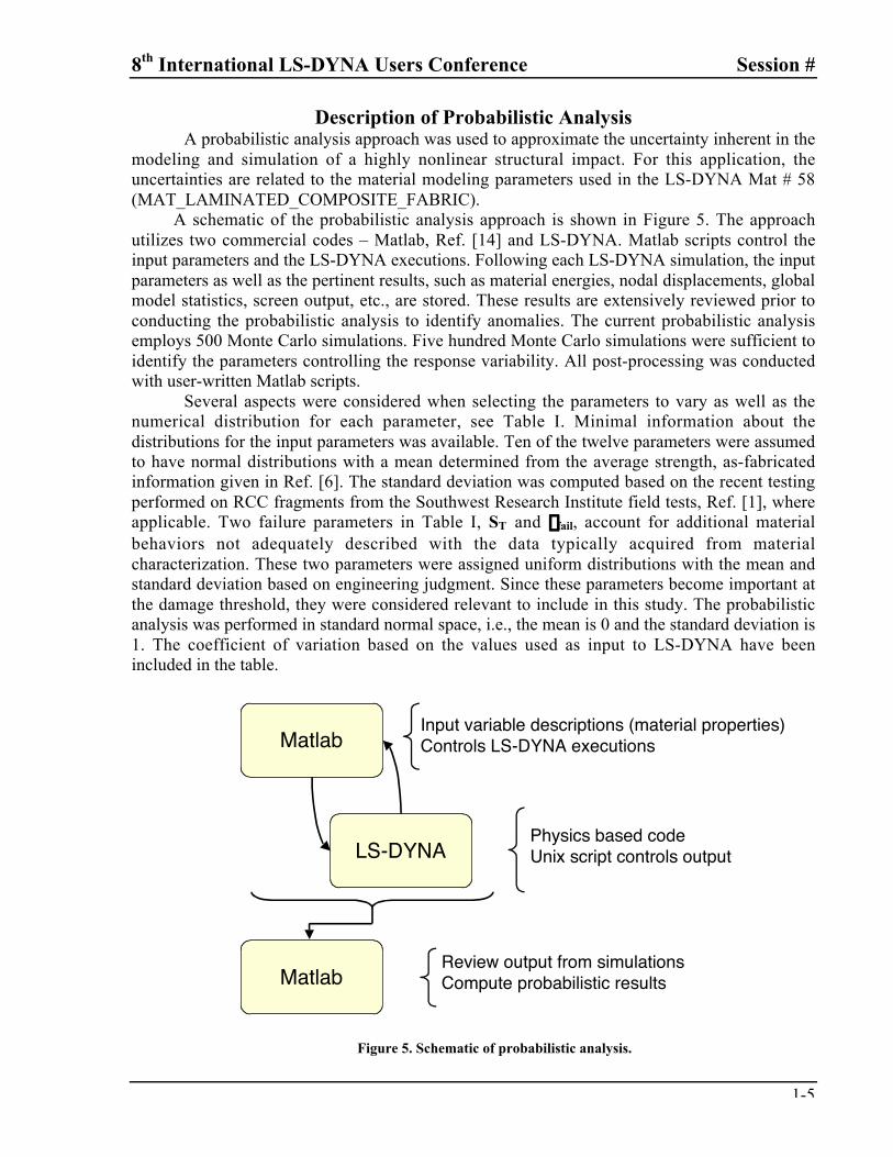
Description of Probabilistic AnalysisA probabilistic analysis approach was used to approximate the uncertainty inherent in the
modeling and simulation of a highly nonlinear structural impact. For this application, theuncertainties are related to the material modeling parameters used in the LS-DYNA Mat # 58(MAT_LAMINATED_COMPOSITE_FABRIC).
A schematic of the probabilistic analysis approach is shown in Figure 5. The approachutilizes two commercial codes – Matlab, Ref. [14] and LS-DYNA. Matlab scripts control theinput parameters and the LS-DYNA executions. Following each LS-DYNA simulation, the inputparameters as well as the pertinent results, such as material energies, nodal displacements, globalmodel statistics, screen output, etc., are stored. These results are extensively reviewed prior toconducting the probabilistic analysis to identify anomalies. The current probabilistic analysisemploys 500 Monte Carlo simulations. Five hundred Monte Carlo simulations were sufficient toidentify the parameters controlling the response variability. All post-processing was conductedwith user-written Matlab scripts.
Several aspects were considered when selecting the parameters to vary as well as thenumerical distribution for each parameter, see Table I. Minimal information about thedistributions for the input parameters was available. Ten of the twelve parameters were assumedto have normal distributions with a mean determined from the average strength, as-fabricatedinformation given in Ref. [6]. The standard deviation was computed based on the recent testingperformed on RCC fragments from the Southwest Research Institute field tests, Ref. [1], whereapplicable. Two failure parameters in Table I, ST and efail, account for additional materialbehaviors not adequately described with the data typically acquired from materialcharacterization. These two parameters were assigned uniform distributions with the mean andstandard deviation based on engineering judgment. Since these parameters become important atthe damage threshold, they were considered relevant to include in this study. The probabilisticanalysis was performed in standard normal space, i.e., the mean is 0 and the standard deviation is1. The coefficient of variation based on the values used as input to LS-DYNA have beenincluded in the table.
Matlab
LS-DYNA
Matlab
Input variable descriptions (material properties)Controls LS-DYNA executions
Physics based code Unix script controls output
Review output from simulationsCompute probabilistic results
Figure 5. Schematic of probabilistic analysis.
Session # 8th International LS-DYNA Users Conference
1-6
Table I. Description of input parameters.
Symbol LS-DYNA parameter DescriptionCoefficientof variation
r RHO Density 0.0258
E EA & EB & EC Young’s modulus 0.0222
n PRBA Poisson’s ratio 0.0435
G GAB & GBC & GCA Shear modulus 0.18
S T SLIMT1 & SLIMT2 Min. tensile stress limit 0.072
efail ERODS Max. eff. strain for layer failure 0.173
eC E11C & E22C Max. compressive strain 0.05
eT E11T & E22T Max. tensile strain 0.14
esh GMS Max shear strain 0.05
sC XC & YC Max compressive stress 0.0343
sT XT & YT Max tensile stress 0.11
ssh SC Max shear stress 0.05
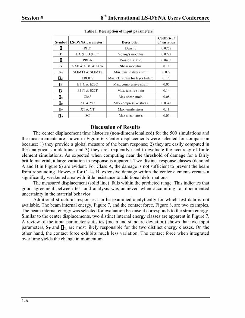
Discussion of ResultsThe center displacement time histories (non-dimensionalized) for the 500 simulations and
the measurements are shown in Figure 6. Center displacements were selected for comparisonbecause: 1) they provide a global measure of the beam response; 2) they are easily computed inthe analytical simulations; and 3) they are frequently used to evaluate the accuracy of finiteelement simulations. As expected when computing near the threshold of damage for a fairlybrittle material, a large variation in response is apparent. Two distinct response classes (denotedA and B in Figure 6) are evident. For Class A, the damage is not sufficient to prevent the beamfrom rebounding. However for Class B, extensive damage within the center elements creates asignificantly weakened area with little resistance to additional deformations.
The measured displacement (solid line) falls within the predicted range. This indicates thatgood agreement between test and analysis was achieved when accounting for documenteduncertainty in the material behavior.
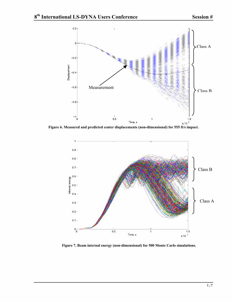
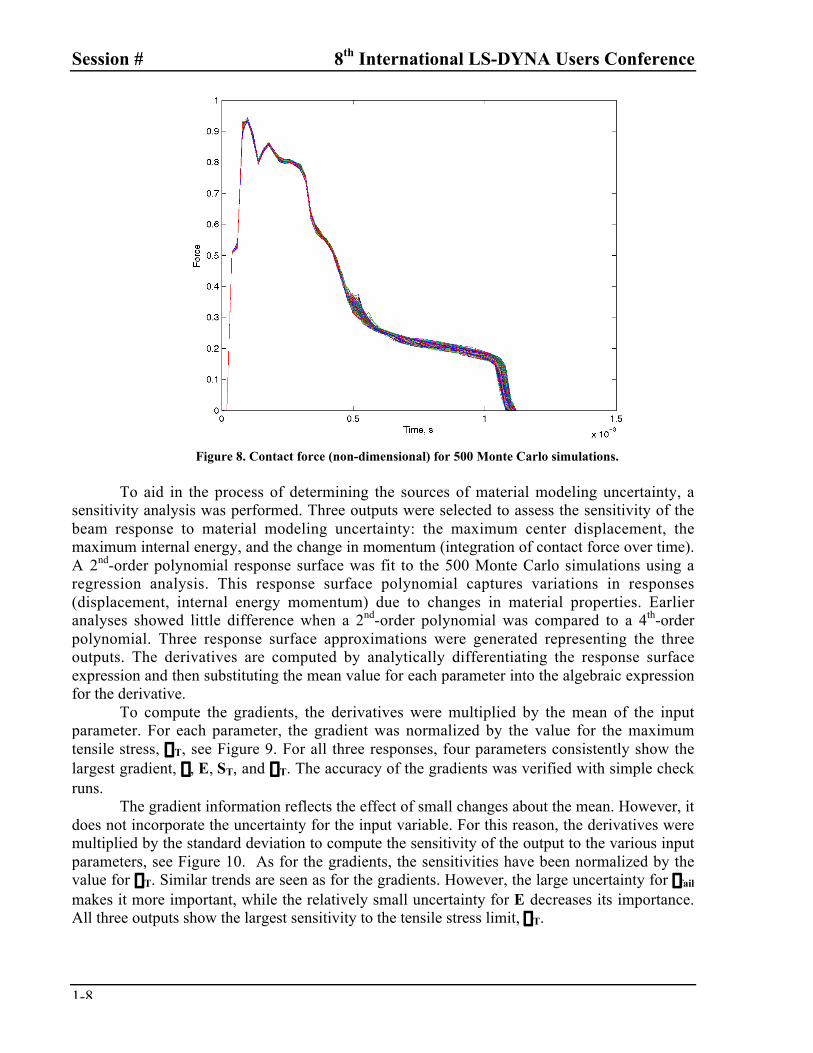
Additional structural responses can be examined analytically for which test data is notavailable. The beam internal energy, Figure 7, and the contact force, Figure 8, are two examples.The beam internal energy was selected for evaluation because it corresponds to the strain energy.Similar to the center displacements, two distinct internal energy classes are apparent in Figure 7.A review of the input parameter statistics (mean and standard deviation) shows that two inputparameters, ST and sT, are most likely responsible for the two distinct energy classes. On theother hand, the contact force exhibits much less variation. The contact force when integratedover time yields the change in momentum.
8th International LS-DYNA Users Conference Session #
1-7
Figure 6. Measured and predicted center displacements (non-dimensional) for 555 ft/s impact.
Figure 7. Beam internal energy (non-dimensional) for 500 Monte Carlo simulations.
Class A
Class B
Class B
Class A
Measurement
Session # 8th International LS-DYNA Users Conference
1-8
Figure 8. Contact force (non-dimensional) for 500 Monte Carlo simulations.
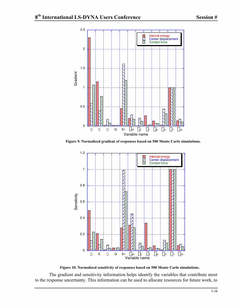
To aid in the process of determining the sources of material modeling uncertainty, asensitivity analysis was performed. Three outputs were selected to assess the sensitivity of thebeam response to material modeling uncertainty: the maximum center displacement, themaximum internal energy, and the change in momentum (integration of contact force over time).A 2nd-order polynomial response surface was fit to the 500 Monte Carlo simulations using aregression analysis. This response surface polynomial captures variations in responses(displacement, internal energy momentum) due to changes in material properties. Earlieranalyses showed little difference when a 2nd-order polynomial was compared to a 4th-orderpolynomial. Three response surface approximations were generated representing the threeoutputs. The derivatives are computed by analytically differentiating the response surfaceexpression and then substituting the mean value for each parameter into the algebraic expressionfor the derivative.
To compute the gradients, the derivatives were multiplied by the mean of the inputparameter. For each parameter, the gradient was normalized by the value for the maximumtensile stress, sT, see Figure 9. For all three responses, four parameters consistently show thelargest gradient, r, E, ST, and sT. The accuracy of the gradients was verified with simple checkruns.
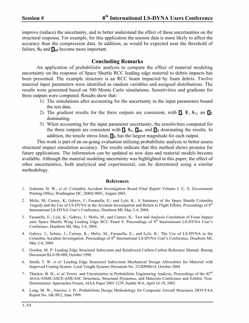
The gradient information reflects the effect of small changes about the mean. However, itdoes not incorporate the uncertainty for the input variable. For this reason, the derivatives weremultiplied by the standard deviation to compute the sensitivity of the output to the various inputparameters, see Figure 10. As for the gradients, the sensitivities have been normalized by thevalue for sT. Similar trends are seen as for the gradients. However, the large uncertainty for efail
makes it more important, while the relatively small uncertainty for E decreases its importance.All three outputs show the largest sensitivity to the tensile stress limit, sT.
8th International LS-DYNA Users Conference Session #
1-9
0
0.5
1
1.5
2
2.5
r E n G ST efail eC eT esh sC sT ssh
Internal energyCenter displacementContact force
Gra
dien
t
Variable name
Figure 9. Normalized gradient of responses based on 500 Monte Carlo simulations.
0
0.2
0.4
0.6
0.8
1
1.2
r E n G ST efail eC eT esh sC sT ssh
Internal energyCenter displacementContact force
Sens
itivity
Variable name
Figure 10. Normalized sensitivity of responses based on 500 Monte Carlo simulations.
The gradient and sensitivity information helps identify the variables that contribute mostto the response uncertainty. This information can be used to allocate resources for future work, to
Session # 8th International LS-DYNA Users Conference
1-10
improve (reduce) the uncertainty, and to better understand the effect of these uncertainties on thestructural response. For example, for this application the tension data is more likely to affect theaccuracy than the compression data. In addition, as would be expected near the threshold offailure, ST and efail become more important.
Concluding RemarksAn application of probabilistic analysis to compute the effect of material modeling
uncertainty on the response of Space Shuttle RCC leading edge material to debris impacts hasbeen presented. The example structure is an RCC beam impacted by foam debris. Twelvematerial input parameters were identified as random variables and assigned distributions. Theresults were generated based on 500 Monte Carlo simulations. Sensitivities and gradients forthree outputs were computed. Results show that:
1) The simulations after accounting for the uncertainty in the input parameters boundthe test data.
2) The gradient results for the three outputs are consistent, with r, E , ST, an sT
dominating.3) When accounting for the input parameter uncertainty, the sensitivities computed for
the three outputs are consistent with r, ST, efail, and sT dominating the results. Inaddition, the tensile stress limit, sT, has the largest magnitude for each output.
This work is part of an on-going evaluation utilizing probabilistic analysis to better assessstructural impact simulation accuracy. The results indicate that this method shows promise forfuture applications. The information can be updated as new data and material models becomeavailable. Although the material modeling uncertainty was highlighted in this paper, the effect ofother uncertainties, both analytical and experimental, can be determined using a similarmethodology.
References
1. Gehman, H. W., et al: Columbia Accident Investigation Board Final Report Volume I. U. S. GovernmentPrinting Office, Washington DC, 20402-0001, August 2003.
2. Melis, M; Carney, K; Gabrys, J.; Fasanella, E.; and Lyle, K.: A Summary of the Space Shuttle ColumbiaTragedy and the Use of LS-DYNA in the Accident Investigation and Return to Flight Efforts. Proceedings of 8th
International LS-DYNA User’s Conference, Dearborn MI, May 2-4, 2004.
3. Fasanella, E.; Lyle, K.; Gabrys, J.; Melis, M.; and Carney, K.: Test and Analysis Correlation of Foam Impactonto Space Shuttle Wing Leading Edge RCC Panel 8. Proceedings of 8th International LS-DYNA User’sConference, Dearborn MI, May 2-4, 2004.
4. Gabrys, J.; Schatz, J.; Carney, K.; Melis, M.; Fasanella, E.; and Lyle, K.: The Use of LS-DYNA in theColumbia Accident Investigation. Proceedings of 8th International LS-DYNA User’s Conference, Dearborn MI,May 2-4, 2004.
5. Gordon, M. P: Leading Edge Structural Subsystem and Reinforced Carbon-Carbon Reference Manual. BoeingDocument KL0-98-008, October 1998.
6. Smith, T. W. et al: Leading Edge Structural Subsystem Mechanical Design Allowables for Material withImproved Coating System. Loral Vought Systems Document No. 221RP00614, October 2004
7. Thacker, B. H., et al: Errors and Uncertainties in Probabilistic Engineering Analysis, Proceedings of the 42nd
AIAA/ASME/ASCE/AHS/ASC Structures, Structural Dynamics, and Materials Conference and Exhibit, Non-Deterministic Approaches Forum, AIAA Paper 2001-1239, Seattle WA, April 16-19, 2002.
8. Long, M. W.; Narciso, J. D.: Probabilistic Design Methodology for Composite Aircraft Structures. DOT/FAAReport No. AR-99/2, June 1999.
8th International LS-DYNA Users Conference Session #
1-11
9. Lyle, K. H.; Padula, S. L.; and Stockwell, A. E.: Application of Probabilistic Analysis to Aircraft ImpactDynamics. Proceedings of the 44th AIAA/ASME/ASCE/AHS/ASC Structures, Structural Dynamics, andMaterials Conference and Exhibit, Non-Deterministic Approaches Forum, AIAA Paper 2003-1758, NorfolkVA, April 7-10, 2003.
10. Lyle, K. H; Stockwell, A. E; and Hardy, R. C.: Application of Probability Methods to Assess Crash ModelingUncertainty. Proceedings of the American Helicopter Society Forum, Phoenix AZ, May 6-8, 2003.
11. Periera, J.; and Revilock, D: The NASA Glenn Research Center Ballistic Impact Laboratory, Proceedings of th54th Meeting of the Aeroballistic Range Association, Sante Fe NM, October 2003.
12. LS-DYNA Keyword User’s Manual (Version 970), Livermore Software Technology Corporation, LivermoreCA 94551, April 2003.
13. Carney, K.; Melis, M.; Fasanella, E.; Lyle, K.; Gabrys, J.: Material Modeling of Space Shuttle Leading Edgeand External Tank Materials for Use in the Columbia Accident Investigation. Proceedings of 8th InternationalLS-DYNA User’s Conference, Dearborn MI, May 2-4, 2004.
14. Using Matlab (Version 6), The Mathwork, Inc., Natick MA 01760, November 2000.