Application of image processing to maintenance of ... · Application of image processing to...
12
Application of image processing to maintenance of signalling facilities N. Nagamine & M. Ukai Signalling and Transport Information Technology Division, Railway Technical Research Institute, Japan Abstract Signalling facilities are important for ensuring safety and stability of train operation, and, the maintenance of signalling facilities have direct relevance to safe and stable train operation. Remote sensing and database management have increased efficiency of maintenance of signalling facilities. Nevertheless, there still remain many types of inspection work requiring human resources in maintenance, such as the visual inspection of facilities, checking the visibility of signals, in particular. These types of inspections still require a large amount of human resources, are highly expensive, lacking in objectivity, and do not have sufficient accuracy. Therefore, we have developed several inspection methods for the maintenance of signalling facilities using image processing technologies, in order to reduce the cost and increase inspection precision. As one example of the developed methods, we have developed a visibility check method of inspection for obstruction warning signals. The signals are important signalling facilities used at level crossings. In addition, the light of the signal is turned off in normal situations, and blinking in abnormal situations. Therefore, as for the inspection of the signals they must be checked with respect to the direction of light emission and conditions of the weeds around them. However, it is not possible to check the visibility of such facilities during train operating hours, because blinking the signal would require interruption of train service. In this paper, we propose a method that employs near infrared LEDs, checking of the visibility of the signals without the interruption of the train operation, and tracking and detecting specific blinking of the signal correctly. Finally, we report Computers in Railways XIII 73 www.witpress.com, ISSN 1743-3509 (on-line) WIT Transactions on The Built Environment, Vol 127, © 2012 WIT Press doi:10.2495/CR120071
Transcript of Application of image processing to maintenance of ... · Application of image processing to...
Application of image processing to maintenance of signalling facilities
N. Nagamine & M. Ukai Signalling and Transport Information Technology Division, Railway Technical Research Institute, Japan
Abstract
Signalling facilities are important for ensuring safety and stability of train operation, and, the maintenance of signalling facilities have direct relevance to safe and stable train operation. Remote sensing and database management have increased efficiency of maintenance of signalling facilities. Nevertheless, there still remain many types of inspection work requiring human resources in maintenance, such as the visual inspection of facilities, checking the visibility of signals, in particular. These types of inspections still require a large amount of human resources, are highly expensive, lacking in objectivity, and do not have sufficient accuracy. Therefore, we have developed several inspection methods for the maintenance of signalling facilities using image processing technologies, in order to reduce the cost and increase inspection precision. As one example of the developed methods, we have developed a visibility check method of inspection for obstruction warning signals. The signals are important signalling facilities used at level crossings. In addition, the light of the signal is turned off in normal situations, and blinking in abnormal situations. Therefore, as for the inspection of the signals they must be checked with respect to the direction of light emission and conditions of the weeds around them. However, it is not possible to check the visibility of such facilities during train operating hours, because blinking the signal would require interruption of train service. In this paper, we propose a method that employs near infrared LEDs, checking of the visibility of the signals without the interruption of the train operation, and tracking and detecting specific blinking of the signal correctly. Finally, we report
Computers in Railways XIII 73
www.witpress.com, ISSN 1743-3509 (on-line) WIT Transactions on The Built Environment, Vol 127, © 2012 WIT Press
doi:10.2495/CR120071
the results of the functional field tests, future development, and other examples of applications of image processing technologies. Keywords: image processing technologies, signalling facilities, obstruction-warning signal, level crossing, visibility check, near infrared LED.
1 Introduction
If something might disturb train operation along the railway line, an obstruction-warning signal informs train driver of the abnormality and need for emergency stop. It is an extremely important facility for safe train operation because it corroborates with several other safety devices; the obstruction warning device for level crossing, the railroad crossing obstacle detection device, the device for clearance disorder alarm, the rock-fall warning device, and gives a flashing light signal. However, the train driver cannot know even if the device does not work correctly because it only gives signal when the train needs to stop (it is different from the fixed signal, which gives signal all the time). The train driver has to recognize the obstruction-warning signal more than 800 m away from the facility in the daytime and the weather is fine. Workers conduct visibility check during visual inspection when obstruction-warning signal is newly built, renewed, or on a periodic basis. The challenge is to check their visibility in train operating hours because it gives signal only when it detects abnormality. With that in mind, a new method has been studied which does not disturb train operation in operating hours, does not depend on workers’ subjective observation, and allows a quantitative check [1–3]. In this paper, in order to apply those methods to the train, obstruction warning signals equipped with a blinking circuit, to flash infrared LED and blink black light in specific periods, pan-tilt cameras to record the LED, and an image processing algorithm to detect the blink of the LED, were developed. Finally, we report the results of the functional field test. There are two kinds of obstruction warning signal; “rotation type” which flash rotates, and “blink type” in which LED arranged vertically and blink. In addition, we used “blink type” throughout this study.
2 Current situation of testing and basic structure of visibility check
2.1 Current situation of testing obstruction warning signal
Newly built and renewed obstruction-warning signals must be checked for visibility by flashing it, from 800 meters away by the workers. Nevertheless, after that test, newly built or removal of building, growth of plants, and/or other forces which change its facing direction might affect their visibility and no longer visible from 800 meters away. In those cases, workers would conduct visibility check. If it does not have sufficient visibility, build the repeater, adjusting its angle, and/or cutting obstructing plants.
74 Computers in Railways XIII
www.witpress.com, ISSN 1743-3509 (on-line) WIT Transactions on The Built Environment, Vol 127, © 2012 WIT Press
When the visibility check is conducted for an obstruction-warning signal at a level crossing, workers split to level crossing; obstruction-warning signal, visibility checkpoint, and force flash the obstruction-warning signal and check the visibility at the checkpoint, photographed if needed. If the newly built or renewed device is not visible from 800 meters away because of the matter of facing direction, the workers adjust the angle while communicating with a wireless device. The traditional method still depends on subjective inspection by workers, not on qualitative evaluation. Furthermore, workers conduct the visibility check which is carried out between the facility and visibility checkpoint. Moreover, it is difficult to flash an obstruction-warning signal in the daytime because it will confuse the train driver, so workers usually conduct the testing at night and it makes the work less effective. There are huge amount of obstruction warning signals installed, therefore, a high-accuracy and effective visibility check method is necessary.
2.2 Requirement specification
To solve those problems, we have developed an on-board visibility check method. Our main focus is on work effectiveness and continuity of visibility. For the on-board inspection method, there are two types of cars: inspection cars, or trains in service. The advantages of inspection cars, is that we can acquire kilometerage easily, and there is less limitation in size of the devices. On the other hand, for using trains, there are two ways to do testing; with the devices fixed on the train, and the devices brought by the workers on-board. Either way, minimizing the size of the device is important, or especially for the latter way, the device should be portable. The advantage of the commercial train, if there is measuring mistake, it is easier to conduct additional testing.
The following shows requirements of both devices.
Light emitting unit Can be installed on current support pillar; Cannot disturb current light emission; Cannot disturb train operation; Has the same visibility.
Measuring unit Allows objective visibility evaluation; Allows testing continuous visibility; Allows visibility check with distinguishing multiple obstruction warning signals.
Based on these requirements, we propose an on-board visibility check method in the next section.
2.3 Proposed method
Obstruction-warning signal emits radio wave or invisible light whose visibility will be checked by our system; this is one method to check visibility during the
Computers in Railways XIII 75
www.witpress.com, ISSN 1743-3509 (on-line) WIT Transactions on The Built Environment, Vol 127, © 2012 WIT Press

daytime without disturbing the train operation. In this case, directionality of radio wave and invisible light must be much higher than that of original light disperse. Unlike radio waves, invisible light is “visible” with a special camera in video to check the result. Therefore, in the case of error-detection, workers can check it easily. Therefore, we selected black light for this research. Black light has an ultraviolet side and infrared side. Because ultraviolet might be hazardous, we selected infrared side light. Although wavelengths of 780 nanometers or longer is in the invisible range, the longer the wavelength, the more difficult to get the LED and less sensible the camera is. Therefore, we selected near-infrared LED (850 or 940 nanometers in peak wavelength.) Moreover, current disperse angle (angle of half intensity) is ±15°, so in this study, disperse angle (angle of half intensity) ±12° LED was selected. Regarding the receiver, we used near-infrared sensible camera and lens. When video record the LED from 800 meters away, LED light is no more than a dot regardless of the shape of arranged LED. In addition, sunlight contains not only visible light but also large amount of infrared light. That peripheral light makes it difficult for us to recognize LED light if the LED is simply lightens. Furthermore, in addition to obstruction-warning signal, variety of light with different wavelength exists along the railway line such as traffic lights, signs, shops’ neon lights, and streetlights. LED light must be accurately among these noises. In order to reduce influence these noises, near infrared LED blinks in certain pattern and make it recognized by the image processing systems. Moreover, in order to distinguish between adjacent obstruction-warning signals, we assign different pattern blinking for individual obstruction-warning signals. In other words, each obstruction-warning signal send unique code pattern to trains, and we decode it by train side. The conceptual figure is as shown in Fig. 1.
Figure 1: Concept of the proposed method.
3 Device structure
We have developed prototype of the near-infrared blinking controller. The LED’s peak wavelength was 850nanometers. In order to adapt to frame rate change of the camera (25fps, 30fps, and 60fps), blinking period can be set arbitrarily by 1 millisecond, and 8 kinds of blinking patterns were available by dipswitch. Moreover, in order to send 3 to 14-bit information when using coding
Level crossing ・・・011011011
・・・001001001
obstruction-warning signal #1
obstruction-warning signal #2
obstruction-warning signal #2○○k○○m
obstruction-warning signal #1○○k○○m
76 Computers in Railways XIII
www.witpress.com, ISSN 1743-3509 (on-line) WIT Transactions on The Built Environment, Vol 127, © 2012 WIT Press

system, which we will mention below, header and coding were manipulated in consideration of later expansion of the code length; it allows maximum 32-bit code length. As for the controller, we used Programmable Logic Controller (PLC). Fig. 2(b) shows controller. Light emitting unit is shown in Fig. 2(a) which we made with the same as current obstruction-warning signal’s system (base plate, acrylic pillar, and cables). For the receiver, Sony XC-EI50 for camera, and KOWA LMVZ9990-IR for lens were equipped.
Figure 2: Prototypes.
4 Blinking pattern and image recognition algorithm
For blinking pattern, we used Manchester coding [4] because it is robust to the environmental change. Manchester coding is a method to embed coding clock rate in the sending data, and it has a characteristic that “0” and “1” are not continuing long. As the result, even though the average level of the amount of received light changed, it does not affect the threshold to decode, and we can synchronize without synchronizing signal. Therefore, it is suitable for this situation in which environmental condition changes significantly and the signal intensity is not stable. Coding system for the digital data in Manchester coding is, “0” putted as “01,” “1” putted as “10.” Binary system with “0” and “1” is defined as transition, not the static value, and two definitions are established by assigning logic level “0” and “1” (and vice versa) to the rising edge and falling edge. In other words, we will find blinking pattern by applying clock signal and exclusive OR. This coding, “0,” and “1” will appear with the same frequency, so we can use average value of the data as decoding threshold. Threshold adjustment is not necessary in places where there are significant environmental change or with environmental noise, and it makes decoding from received data easy. For decoding procedure, find the average and take difference from the observed (or threshold processing with average value as threshold) to be digital data. Through clock and exclusive OR process, digital data decoded back to be original. When it applied to image processing, k-th flame image is , and its pixel value is,
PLC
Batt
SW
NF
Driver
(a) Light emitting unit (b) Controller
Computers in Railways XIII 77
www.witpress.com, ISSN 1743-3509 (on-line) WIT Transactions on The Built Environment, Vol 127, © 2012 WIT Press

, , average image between k-th flame and L-th flame is , , differential image of , and , is , , and if , which binalized conforming with code pattern is , , the formula is shown below, and the pixel with only code pattern is , . In the end, we conduct k-th flame visibility check, and interpret the result as passed test 1, and as not passed test 0,
, ∑ , ⁄
, , ,
for 1,1
,1 , 00 , 0
(1)
, ∏ ,
∏ ∏ ,
Below, image processing decoding screenshots are shown, a part of the received data in Fig. 3(a), the average received data in Fig. 3(b), and digital data generated from difference between received data and average in Fig. 3(c).
Figure 3: Decoding process by image processing.
(a) Received image (b) Average image
(c) Differential binary image
78 Computers in Railways XIII
www.witpress.com, ISSN 1743-3509 (on-line) WIT Transactions on The Built Environment, Vol 127, © 2012 WIT Press

5 View control of near-infrared camera
5.1 The need for camera view control
When you look at 800 meters away with non-zoom wide-angle camera, one pixel size’s width corresponds to a few decimeters to one meter. Therefore, the image size of obstruction-warning signal is completely smaller than one pixel. Even if it blinks, it is very hard to recognize it. In addition, when a zoom camera is used, obstruction-warning signal with one or two pixel, focus length supposed to be 90 millimeters for the prototype structure. In this case, angle field θ is, focus length f and filming distance L, expressed as θ = atan (L/2/f) × 2. Moreover, it is about four degrees. Fig. 4(a) shows covered region by the lens in a forward-looking camera installed in a driver’s cab as a square, and it obviously does not cover the sufficient field of vision. Although zoom camera in straightaway cover driver’s point of gaze, however, in curved section like in Fig. 4(b), zoom camera cannot cover the obstruction-warning signal because it is on the left side of screen. Therefore, in order to shoot the signal with camera from 800 meters away, we need camera view control by recognizing the rail direction. Then, effective method of camera view control by extracting rail from the image from a wide-angle camera, and decide the viewing direction by finding Focus of Expansion (FOE).
Figure 4: Object is out of the covered area at curved section.
5.2 Rail extraction algorithm
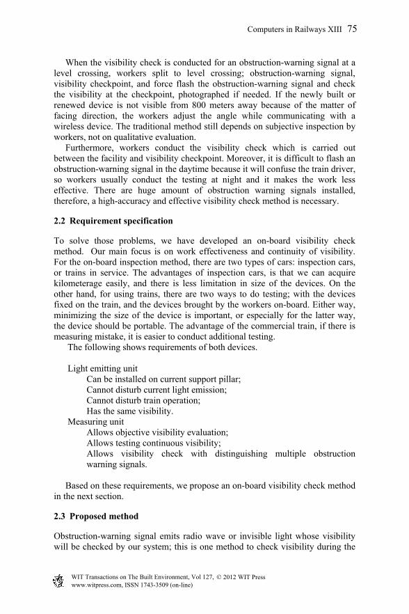
Near the camera, we observe rail with comparatively strong edge, and it is almost straight because the curvature is moderate. Moreover, the larger the distance from the camera is, the narrower it looks. We employed existing algorithm, in which are rails combination of short line and curve segment [5]. From far end of rail template specified with near-field range processing, next candidate rail-lines are drown in consideration of the template’s curvature. From those candidates, the algorithm chose lines, which matches the rail image. The farther from camera, the more divided the search area; repeatedly extracting rail in the next area. Fig. 5 shows the result of rail extracting algorithm applied in practice. Fig. 5(a) has noise by raindrops, and Fig. 5(b) has halation because of
(a) Straight way (b) Curved section
Zoom camera’s angle of field Zoom camera’s angle of field
Computers in Railways XIII 79
www.witpress.com, ISSN 1743-3509 (on-line) WIT Transactions on The Built Environment, Vol 127, © 2012 WIT Press
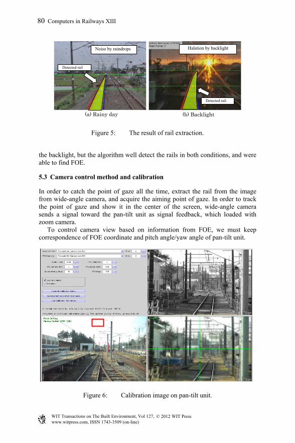
Figure 5: The result of rail extraction.
the backlight, but the algorithm well detect the rails in both conditions, and were able to find FOE.
5.3 Camera control method and calibration
In order to catch the point of gaze all the time, extract the rail from the image from wide-angle camera, and acquire the aiming point of gaze. In order to track the point of gaze and show it in the center of the screen, wide-angle camera sends a signal toward the pan-tilt unit as signal feedback, which loaded with zoom camera. To control camera view based on information from FOE, we must keep correspondence of FOE coordinate and pitch angle/yaw angle of pan-tilt unit.
Figure 6: Calibration image on pan-tilt unit.
(a) Rainy day (b) Backlight
Halation by backlight Noise by raindrops
Detected rail
Detected rail
80 Computers in Railways XIII
www.witpress.com, ISSN 1743-3509 (on-line) WIT Transactions on The Built Environment, Vol 127, © 2012 WIT Press
We have developed calibration program, which registers one point of image of wide-angle camera and one point of near-infrared image controlled at pan-tilt unit as teacher coordinate by GUI. Fig. 6 shows screenshot of calibration, in which wide-angle camera view is on the bottom-left. Red square shows the area, which is the same zoom rate of near-infrared camera; Zoomed image on the bottom-right, and near-infrared camera image on the upper-right. Each image adjusted as looked the same size, and registered as calibration coordinate and teacher coordinate in the program. At least four correspondence points registered makes calibration work accurate, consequently, camera view control works accurate on coordinate extracted by rail extraction algorithm.
6 On-track test
6.1 Temporary installation
We installed the support pillar of current obstruction-warning signal to evaluate those prototype emitting unit, controller, pan-tilt unit, blink detection algorithm, and prototype-emitting unit. Moreover, we measured in the daytime with train, checking the effectiveness of this method. The test location is between Akigawa station and Musashi-hikida station on Itsukaichi Line, and we installed the prototype of emitting units from the start point of outbound direction as shown in Table 1.
Table 1: The location of prototype obstruction warning signals.
Prototype # Name of level crossing Device name Installed kilo A Yotsugi-daini level crossing XF2 6k040mB Fuchigami-daiichi level cross XF2 6k100mC Yotsugi-daini level crossing XF1 6k259mD Fuchigami-daiichi level cross XF1 6k548mE Hikida level crossing XF1 7k029m
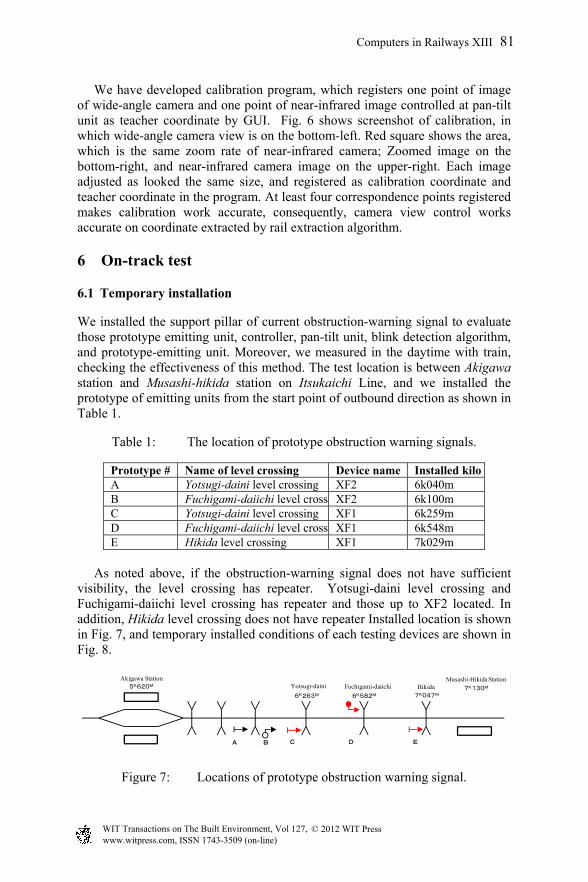
As noted above, if the obstruction-warning signal does not have sufficient visibility, the level crossing has repeater. Yotsugi-daini level crossing and Fuchigami-daiichi level crossing has repeater and those up to XF2 located. In addition, Hikida level crossing does not have repeater Installed location is shown in Fig. 7, and temporary installed conditions of each testing devices are shown in Fig. 8.
Figure 7: Locations of prototype obstruction warning signal.
Akigawa Station Musashi-Hikida Station5K620M
7K130MHikidaFuchigami-daiichiYotsugi-daini
7K047M6K582M6K263M
A B C D E
Computers in Railways XIII 81
www.witpress.com, ISSN 1743-3509 (on-line) WIT Transactions on The Built Environment, Vol 127, © 2012 WIT Press

Figure 8: Temporary installation of prototype.
6.2 On-track test
We carried out an on-track test, in which we used turn-back operation train running between Haijima station and Musashi-Itsukaichi station. We installed devices on assistant driver’s side of the cabin on Musashi –Itsukaichi side. We conducted visibility checks six times from 12:00 to 18:00. This was for evaluating the difference of the effects of environmental light. As for the blinking pattern, zero to seven expressed with three bit, and each bit changed into Manchester code such as “0” for “01”, “1” for “10”. Then we added sentence starter recognition four-start bit “1100” to coded six bit, and completed total 10-bit pattern. For example, we express “5” as “1100100110”. Five prototype-emitting units assigned different patterns.
Figure 9: On-board measuring system.
Figure 10: Devices set.
Infrared camera
Wide-angle camera
Pan-tilt unit
Rail extraction result
Wide-angle camera image
Infrared camera image
(a) Appearance of on-board measure (b) On-board measure system screen
Infrared camera
BatteryPC
Recorder
Pan-tilt unit
Wide-angle camera
Unit A Unit C Unit D Unit E Unit B
82 Computers in Railways XIII
www.witpress.com, ISSN 1743-3509 (on-line) WIT Transactions on The Built Environment, Vol 127, © 2012 WIT Press

Fig. 9 shows structures of the device in the test train. Computer analyzed image by wide-angle camera, and send control signal to pan-tilt unit based on FOE information to control view of infrared camera. Infrared camera allows recording long time with external storage. Fig. 10(a) shows how the device set in the train, and Fig. 10(b) shows system screen.
6.3 Results
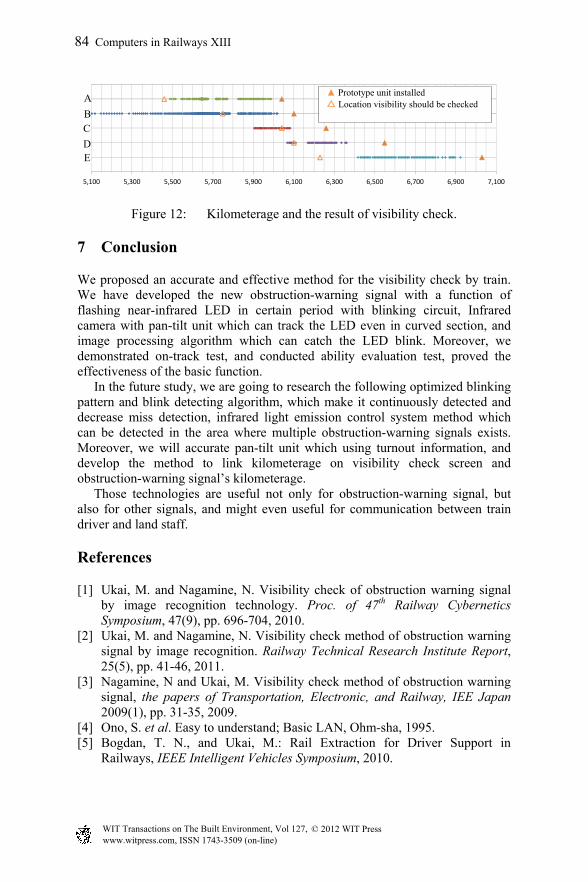
Fig. 11 shows the screenshot when the prototype emitting units A–E are detected. In addition, the results of the test are shown in Fig. 12, where the horizontal axis is kilometerage, and the vertical axis is prototype number. “Filled triangle” is a kilometerage installed prototype-emitting unit, “Margined triangle” is the kilometerage as should be recognized. “Diamond” shows the location where the system detected the prototype-emitting unit.
Figure 11: System confirms the visibility.
For unit A, B, C, and D, visibility was successfully checked at the location where it should be recognized. Especially, the system detected the unit B from 600 meters away from it. It is because the unit B is repeater, it is open place and well sighted, train vibration was unaffected, and camera view control worked well. There are some miss-detected spots between the visibility confirmed areas in each result, especially at 5k450m of unit A. It is because train vibration affected the blink detection algorithm, which resulted in miss-detection. Miss-detected area at 5k800 m (unit A and B), 6k150m (unit D) are because of the failure of rail extraction algorithm, and it failed to control camera direction. For unit E, as it should be recognized at 800-m away from it located, it finally detected 600 meters away. This miss-detected is also because of the train vibration and the failure of camera view control. Zoom camera could not capture the unit from 100 meters to 150 meters away from every unit because it was too close. The algorithm well detected unit C even though it was located after passing the curved section, and it shows the effectiveness of camera view control.
Unit A Unit B Unit C
Unit E Unit D
Detected Detected
Detected
Detected Detected
Computers in Railways XIII 83
www.witpress.com, ISSN 1743-3509 (on-line) WIT Transactions on The Built Environment, Vol 127, © 2012 WIT Press
5,100 5,300 5,500 5,700 5,900 6,100 6,300 6,500 6,700 6,900 7,100
Figure 12: Kilometerage and the result of visibility check.
7 Conclusion
We proposed an accurate and effective method for the visibility check by train. We have developed the new obstruction-warning signal with a function of flashing near-infrared LED in certain period with blinking circuit, Infrared camera with pan-tilt unit which can track the LED even in curved section, and image processing algorithm which can catch the LED blink. Moreover, we demonstrated on-track test, and conducted ability evaluation test, proved the effectiveness of the basic function. In the future study, we are going to research the following optimized blinking pattern and blink detecting algorithm, which make it continuously detected and decrease miss detection, infrared light emission control system method which can be detected in the area where multiple obstruction-warning signals exists. Moreover, we will accurate pan-tilt unit which using turnout information, and develop the method to link kilometerage on visibility check screen and obstruction-warning signal’s kilometerage. Those technologies are useful not only for obstruction-warning signal, but also for other signals, and might even useful for communication between train driver and land staff.
References
[1] Ukai, M. and Nagamine, N. Visibility check of obstruction warning signal by image recognition technology. Proc. of 47th Railway Cybernetics Symposium, 47(9), pp. 696-704, 2010.
[2] Ukai, M. and Nagamine, N. Visibility check method of obstruction warning signal by image recognition. Railway Technical Research Institute Report, 25(5), pp. 41-46, 2011.
[3] Nagamine, N and Ukai, M. Visibility check method of obstruction warning signal, the papers of Transportation, Electronic, and Railway, IEE Japan 2009(1), pp. 31-35, 2009.
[4] Ono, S. et al. Easy to understand; Basic LAN, Ohm-sha, 1995. [5] Bogdan, T. N., and Ukai, M.: Rail Extraction for Driver Support in
Railways, IEEE Intelligent Vehicles Symposium, 2010.
A
B C
D E
▲ Prototype unit installed △ Location visibility should be checked
84 Computers in Railways XIII
www.witpress.com, ISSN 1743-3509 (on-line) WIT Transactions on The Built Environment, Vol 127, © 2012 WIT Press