
APPLICATION OF HYDROCYCLONES FOR RECOVERY OF FINE
32
PRopUn OF AL4SKA STdn ~~LOGKB~L SERV;~ LB~Y M IRL Report No- 55 APPLICATION OF HYDROCYCLONES FOR RECOVERY OF FINE GOLD FROM PLACER MATERIAL BY P. Dharma Rao Ernest N. Wolff David R. Maneval Mineral lndustry Research Laboratory School of Mineral Industry University of Alaska Fairbanks, Alaska 99701
Transcript of APPLICATION OF HYDROCYCLONES FOR RECOVERY OF FINE
PRopUn OF AL4SKA STdn ~ ~ L O G K B ~ L SERV;~ L B ~ Y
M IRL Report No- 55
APPLICATION OF HYDROCYCLONES FOR RECOVERY OF FINE GOLD FROM
PLACER MATERIAL
BY P. Dharma Rao Ernest N. Wolff
David R. Maneval
Mineral lndust ry Research Laboratory School of Mineral Industry
University of Alaska Fairbanks, Alaska 99701


MIRL Rewrt No. 55
Final Report
APPLICATION OF HYDROCYWJES FOR R E m Y OF FINE COLD m M PLACER MATERIAL,
Mining and Mineral Resources &search Institute Office of Surface Mining
U.S. Department of Interior Washington, D.C. 70740
Grant No. G5194003
P. D h a m Rao
Ernest N. Wolff
David R. Maneval
Mineral Industry Research Laboratory School of Mineral Industry
University of Alaska Fairbanks, Alaska 99701

The views and conclusions contained i n this document
are those of the author and should not be interpreted
as necessarily representing t h e official p o l i c i e s or
recommendations of the Interior Department's Office of
Surface Mining or of the U.S. Government.

. . . . . . . . . . . . . . . . . . Introduction
Concentration Cyclones . History and Principles
. . . . . . . . . . . . . Experimental Procedure
. . . . . . . . . . . . . . . Sources of Samples
Experimental Results . . . . . . . . . . . . . . Lillian Creek. (Livengood) Sample . . . . . Ready Bullion Creek (Ester Dane) Sample . . Cleary Creek (Pedro Dane) SarcQ?le . . . . .
Discussion . . . . . . . . . . . . . . . . . . . . . . . . . . . . . . . Sumnary and Conclusions
. . . . . . . . . . . . . . . . . . . . . . . . . . . C o n d u s i m 22
. . . . . . . . . . . . . . . . . . . . . . . . . . . Acknowledgements 25
. . . . . . . . . . . . . . . . . . . . . . . . . . . . . Bibliography 26
Figure 1 . Camparison of Design Features of a Compound Water . . . . . . . . . . . . . Cyclone and a Classifying Cyclone 4
Figure 2 . Separating process in a Campound Water Cyclone (15) . . . . . 5
Figure 3 . Design of Fyrex Compound Water Cyclone Used for Laboratory Investigations . . . . . . . . . . . . . . . . . 7
Figure 4 . A closeup photograph of the ccmpound water cyclone . . . . . 8
. . . . . . . . . Figure 5 Experimental setup with a constant head tank 8
Figure 6 . Block diagram showing testing procedures followed . . . . . 9
Figure 7 . Wo-Stage Compound Water Cyclone Concentration With Auto- . . . . -matic Control (Cyclone Engineering Sales Ltd.. Canada 24

Table 1. Size - specific gravity distribution of products of two stage CW cyclone concentration of -65 mesh gold placer ma- terial, Lillian Creek, (Livengood) Figures in weight . . . . . . . . . . . . . . . . . percent of total feed 11
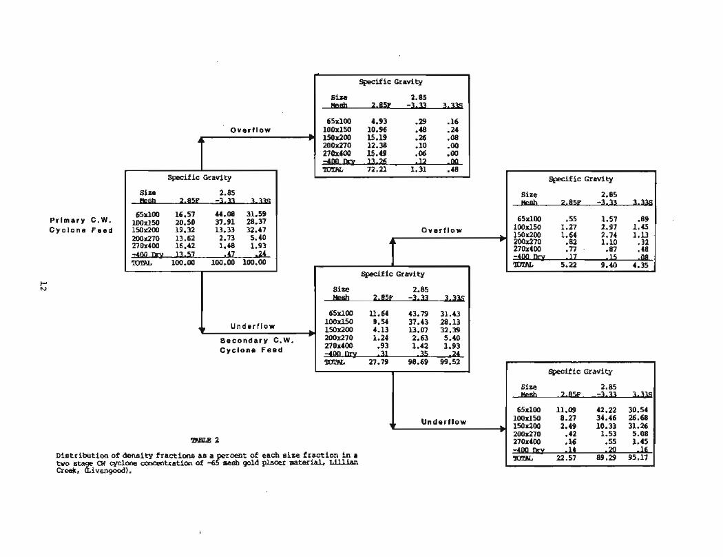
Table 2. Distribution of density fractions as a percent of each size fraction in a two stage cyclone concentration of -65 mesh gold placer material, Lillian Creek (Livengood) . . . . . . . . . . . . . . . . . . . . . . 12
Table 3. Distribution of density fractions in weight percent for each size in a two stage CW cyclone concentration of 4 5 gold placer material, Lillian Creek, (Livengood). , 14
Table 4. Size - specific gravity distribution of products of two stage CW cyclone concentration of -65 mesh gold placer, Ready Bullion Creek (Ester . Figure in weight percent of total feed . . . . . . . . . . . . . . . . . 15
Table 5. Distribution of density fractions as a percent of each size fraction in a two stage 0 7 cyclone concentration of -65 mesh gold placer material, Ready Bullion Creek (Ester) . . . . . . . . . . . . . . . . . . . . . . . . 16
Table 6. Distribution of density fractions in weight prcent for each size in two stage OW cyclone concentration of -65 gold placer material, Ready BUlion Creek (Ester) . . . . . . . . . . . . . . . . . . . . . . . . 17
Table 7. Size - specific gravity distribution of products of two stage CW cyclone concentration of -48 mesh gold placer, Cleary Creek (Pedro) . Figures in weight percent of total feed . . . . . . . . . . . . . . . . . 18
Table 8. Distribution of density fractions as a percent of each size fraction in a two stage CW cyclone concentration of -65 mesh gold placer material, Cleary Creek . . . . . . . . . . . . . . . . . . . . . . . (Pedro). 20
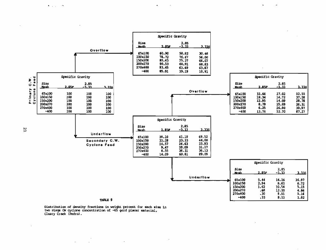
Table 9. Distribution of density fractions in weight percent for each size in two stage CW cyclone concentration of . . . . -65 gold placer material, Cleary Creek (Pedro). 21

Alaska and other gold areas have seen a sharp resurgence of placer mining in the last few years. Mines using sluice boxes usually recover gold down to 100 mesh, but recovery of gold finer than this size is a function of particle shape factor, sluice box design and operating parameters. It is felt that a concentrating device is needed to recover gold finer than 100 mesh that may not be recoverable in a sluice box. The device should be capable of proces- sing a large volume of water and solids discharged from the sluice-box. Compound water cyclones, successfully used in the coal processing industry, seem to offer solutions. A system using these devices could recover a concen- trate which would be one twenty fifth the size of the original solids in a two stage process. It is not intended to produce a finished product with cy- clones, but to reduce bulk so that the reduced concentrate, free of slimes, could further be treated by flotation, gravity methods, or cyanidation to isolate the gold. This reprt addresses only the application of hydrocyclones for concentrating gold from placer material.
m t r a t i m C j d m - Elistory and Principles
The hydrocyclone is a device used in the treatment of aqueous mineral suspensions for the purpse of wet separation. The basic structure is tht of a tapering, hollow body or cone. The fluid stream is introduced tangentially through a peripheral inlet and is transformed into a spiral flow moving from the inlet to the apex. The taper induces a back flow along a central core which spirals toward the inlet section, while the high centrifugal accelera- tions of the vortex cause the particles to separate and move in the direction of the apex (4).
The centrifugal force developed accelerates the settling rate of the particles (there is evidence to show that Stokes' law applies with reasonable accuracy to separations in cyclones of conventional design), thereby separat- ing particles according to size and specific gravity. Faster settling parti- cles move to the wall of the cyclone where the velocity is lowest and migrate to the apex opening (5,6).
Many determining factors control the direction of flow of a particle in a hydrocyclone. Dreissen and Fontein, (5) list the following:
Shape of particle Solids concentration Feed pressure Back pressure Cyclone diameter Diameters of the feed opening Overflcrw opening Apex opening Length of the cylindrical part (vortex finder) Cone angle

11) Specific gravity 12) Average grain size of the particle 13) Solids concentration of the inlet feed and apex discharge 14) Viscosity of the feed suspmsion and the liquid
Historically the main use of cyclones in mineral processing is as classi- '
fiers. These have proved extremely efficient at fine separation sizes. ney are used increasingly in closed circuit grinding operations butthey have found many other uses, such as desliming, degritting and thickening, and recently for concent rating.
It has been shown that under the best conditions, satisfactory separation with a conventional cyclone can be obtained for coal cleaning only up to 1.6 specific gravity (7,8). The results obtained with single CW Cyclones show that their applicability is not restricted to cleaning coal of up to 1.6 specific gravity, but covers the entire range of cut points. In addition, it has been found that the presence of a hindered settling bed enables the processing, in unstable suspension, of mineral sands and ores (7).
However a cyclone cannot efficiently both classify and concentrate feed. It is not possible for a given cyclone to perform both functions simultane- ously at maximum efficiency-an increase in classification efficiency auto- matically results in a decrease in concentration efficiency. This correlation between concentration inefficiency and classification efficiency is under- standable when one considers that, for high concentration efficiency, the cyclone is expected to make a separation in which coarse, light particles report to the overflow, and fine, heavy particles (gold-pyrite for example) report to the spigot at the apex. This is contrary to the normal tendency of the cyclone to act basically as a classifier (9).
Recent years have seen the development of various cyclones spcifically for concentrating purposes. Their physical design is such that classification effects are suppressed and the influence of particle specific gravity is maximized. These are not heavy-medium cyclones, which have been in use in the mineral processing industry for some years, but true hydrocyclones. They were developed largely as a result of work in the coal industry (81, where cyclones operating with a water medium are now in wide use for upgrading fine coal. Investigations have also been carried out into the use of cyclones for the beneficiation of cassiterite (10,111 and iron ores, and a recent Russian paper (12) describes the concentration of gold from milled conglomerate ores by use of a short cone hydrocylone (9).
Classification cyclones are of slender design, with a narrow cone angle- usually 15 to 30 degrees. In these cyclones, the particles must discharge either through the vortex finder or the apex orifice, and the basic require- ment for separation is the achievement of balance between the centrifugal forces accelerating the particles radially outward and the centripetal drag forces. For this purpose, relatively large vortex finder clearances are .common in classification cyclones, because this assists in providing the time for particles in the central flow region to reach their terminal free settling velocity relative to the entraining water (9).

In contrast, concentrating water hydrocyclones are of squat design, with a wide cone angle-in the range 60 to 180 degrees--and long large diameter vortex finders. They are called compound water (cw) cyclones because of the compund slops to their sides. They are o~rated to suppress classification phenomena in favor of gravity concentra tion effects. Briefly, their design is based on two hypotheses (8): (a) a particle bed stratifies according to density along the conical wall of the lower cyclone section, and b) particles entering the central spiral flow separate during the initial phase of their acceleration in a radial direction. The former hypothesis has led to the selection of wide cone angles for concentrators, because particles stratify more reliably along the shallower wall of a wide cone than would be pssible along the steep wall of a slender cone. The latter hypothesis has led to the preference for relatively short vortex finder clearances in concentrators, because this design assists in separating particles that swirl toward the vortex finder before the centrifugal mass and the centripetal drag forces acting on these particles attain equilibrium. Since it is the drag force that increases the relative influence of particle size on separation, this force must be suppressed in the operation of cyclones as concentrators (9). Figure 1 shows the basic design of each type, classifying and concentrating.
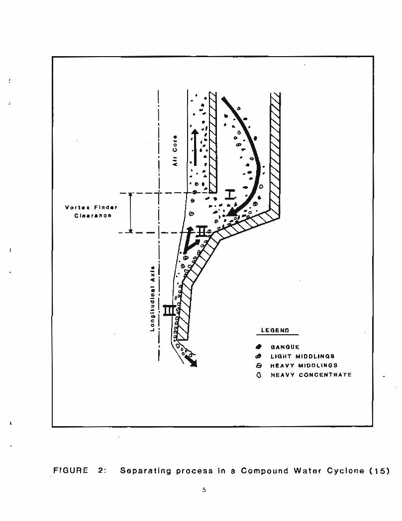
The CW cyclone has been described by Visman (7) as having three effective sections as shown on Figure 2. Particles of different sizes and specific ,gravity form a hindered settling bed in Section I of the compound cone. Light, coarse particles are prevented from penetrating the lower strata of this bed by the coarse, heavy fractions and by the fine particles filling the inter- stices of the bed. Consequently, the water passing from the periphery of the cyclone chamber towards its main outlet (the vortex finder) erodes the top of the stratified bed and substantially removes the light, coarse particles via the "central currentm around the air core.
The remainder of the bed is forced into the second conical section (11) by new feed entering the cyclone, substantially without losing its stratified character. Here, the central current is much stronger and erodes the top of the bed, where the middlings are now exposed. The high middlings are swept up and discharged through the vortex finder.
'Ihe heavy middlings that spiral upward in the central current may bypass the orifice of the lower vortex finder owing to their higher specific gravity. Consequently, the coarse heavy middlings fraction tends to recirculate to the stratified bed and finally enters the third conical section. In this last section (1111, the bed is finally destroyed as coarse particles fan out along the cyclone wall in a single layer, exposing the small particles that so far have been protected from being washed out. The central current in Section I11 is relatively weak as it has nearly spent itself in the previous sections. The upward current that remains separates the small particles from the remainder of the material, with preference for those of low specific gravity. Thus the fine, light particles are finally discharged through the vortex finder by a process of elutriation. The heavy particles, fine as well as coarse, are discharged through the apex. The separation thus takes place in three steps, (Figure 2).

V o r t e x Finder C l e a r a n c e
LEQENO
QANQUE
& LIGHT MIDDLINGS
8 H E A V Y MIDDLINGS
HEAVY CONCENTRATE
L
FIGURE 2: Separating process in a Compound Water Cyclone (15 )

A review of the literature as cited above indicated to the authors that for short duration bench scale testing, a CW cyclone of pyrex glass could be used. Figure 3 is a diagram of the CW cyclone, which was fabricated from pyrex glass. The vortex finder can be moved to adjust its position. The apex is varied by fitting tygon tubing inserts in the orifice. Figure 4 is a closeup photograph of the C V J cyclone. Figure 5 shows the experimental setup with a constant head tank arranged for accurately adjusting the head for the CW cyclone.
Several tests were conducted to determine the optimum water head for the Eeed tank and the optimum diameter of the apex orifice. The vortex finder diameter was kept constant. The apex orifice diameter of 1/4n was chosen to allow most of the inlet feed to overflow, with a minimum reporting out the apex spigot as underflow. The water (feed) head was set at 55 inches, again to obtain maximum overflow. The test conditions used were as follows:
cyclone head 55 in. (139.7 an.) apex orifice 1/4 in, (0.635 cm.) vortex finder diameter 1 in. (2,540 cm, 1
f l a w rate: overflcrw = 8.24 gal./min. (31. liters/min. 1
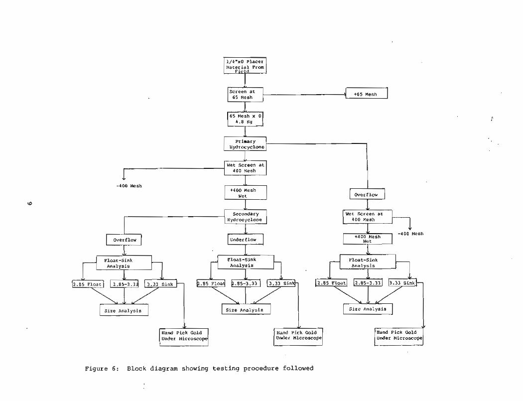
Figure 6 shows the general flow sheet followed in this project. For two of the samples tested, the feed material was screened at 65 mesh. For one sample, the feed was screened at 48 mesh. All oversize material was rejected. The wet screened Eeed was slurried and fed manually from the head tank to the primary CW cyclone at a constant rate and the products were collected. The CW cyclone underflow for Lillian Creek sample was deslimed (wet screened) over 400 mesh and the +400 material was passed through the secondary CW cyclone. Both the overflow and underflow secondary CW cyclone products were sink- floated at 2.85 and 3.33 specific gravities. Gold particles from the 3.33 sink fractions of both underflow and overflow products were hand picked under the microscope and/or analyzed chemically. A l l of the float-sink products (2.85 float, 2.85-3.33, and 3.33 sink) were screened for size analysis. The 3.33 specific gravity sinks form only a small percentage of the whole, and in order to preserve accuracy, all data were calculated to 4 decimals.
Sources of sanples
Three placer mine samples were tested in this project. A 1 1 three were geologically similar; i.e. strean alluvium. The samples and sources were as follows :

Overflow
FIGURE 3: Design,of Pyrex Compound Water Cyclone Used for Laboratory Investigations

F i g u r e 4: A closeup photograph of the compound water cyclone
F i g u r e 5: Experimental setup with a constant head tank
8
1/4"x0 P l a c e r M a t e r i a l From
.t Screen a t +65 Mesh
65 Mesh
J. 65 Mesh x 0
4.0 Kg
1 Wet S c r e e n a t
1 4 0 0 Mesh
-400 Mesh 1 +400 Mesh
wet I
Secondary
I Hydrocyclone I
Overf low + Float -S ink
A n a l y s i s
Under f l o w 11 Float -S ink
A n a l y s i s h . 85 load b.85-3.33 j (3 .33 S i n
( s i z e A n a l y s i s I
Hand P ick Gold Under Pl icroscope
Overf low & Wet Screen a t
+400 Mesh i -400 !Iesh
F loa t -S ink A n a l y s i s
S i z e A n a l y s i s
Under Microscope
2 . 8 5 F l o a t 2.85-3.33 3.33 Sink . ?EZ? 1 S i z e A n a l y s i s I I
Under Microscope
F i g u r e 6: Block diagram showing t e s t i n g procedure followed

Creek Mining Presumed Mine mule USol l rce Owner
Lillian Creek Livengood Money Knob Carl Parker (deceased) Ready Bullion Creek Fairbanks Ester Dane Jerry Hassel Cleary Creek Fairbanks PedroDoane Oscar meiten
In placer mining, typically, overburden o r muck has been removed t o expose the gold baring gravels. Sometimes the upper, barren gravels are also removed. The run of mine material is then processed i n a sluice box, trommel or similar device t o remove gravel and l ight coarse sands. The bucket samples which were used i n t h i s p ro jec t were taken from t h i s "scalpedn material . Further description of sample preparation w i l l be found la ter i n t h i s report. A11 three mines were located on creeks about one half mile downstream from the nearest known lode deps i t .
Lillian _Creek. l L U 3 l ~ ~ ) samEdJ2
Table 1 gives the d i s t r i b u t i o n of various s i z e and s p e c i f i c gravi ty fractions as a weight percent of £4 t o the primary CW cyclone. The primary CW cyclone rejected 76% of the feed with very l i t t l e loss of 3.33 sinks. Tbe feed t o the primary CW cyclone had 37.8% -400 mesh material; only 3.1% of the feed i n this size range reported t o the underflow. Note t h a t the -400 mesh fraction appears twice, once as wet and once as dry. The i n i t i a l wet screen- ing removed most of the -400 mesh mate r i a l (Figure 6). The -400 mesh dry material a m a r e d i n the size analyses of float-sink products.
The gold recovered was a s follows:
NO. of Gold Gold Gold Weight, Recovered,
Percent
Primary CW cyclone overflow 1 0.1 . 2 Secondary CW cyclone overflow 3 0.1 .2 Secondary CW cyclone underflow 1130 51.2 99.6
Thus a recovery of more than 99.5% of the gold has been achieved i n the two passes through the CW cyclones. The amount of gold in the -400 mesh fraction is negligible, i n fact, very l i t t l e i f any gold was found that was finer than 200 mesh
Table 2 shows the distribution of various s ize fractions as a percentage of each of the three s p e c i f i c gravi ty f r ac t ions , 2.85 floats, 2.85 t o 3.33, and 3.33 sinks. I n the primary CW cyclone, f o r 2.85 f l o a t s , t h e 65x100 mesh reported more i n underflow than overflow: the 100x150 mesh underflow and overflow reported about equally, whereas f o r s i z e s smaller than 150 mesh, rejection of material t o overflow was more efficient

I ' Specific Gravity I
Primary C . W . Cyc lone Feed
Distribution of density fractions as a r a n t of each sire fract ion i n a two stage cy*- cmcentration d"L=* placer =widil, L i . ~ i m Creek, (Livengood).
Overf low A b
-
65w100 4.93 .29 .16 10Oxl50 10.96 .40 .24 lMx2W U.19 .26 .08 200x270 12.38 .10 .00 270x400 15.19 .06 .00
13.26 12 M 'IMIAC 72.21 ' l.U .48
Specific Gravity
Si~e 2.85 - 3 - q 3
65r100 16.57 44.08 31.59 100~19 20.50 n.91 28.37 150x200 19.32 U.33 32.47 200r270 13.62 2.73 5.40 270x400 16.42 1.48 1.93
47 .24 m 100.00 100.00 100.00
s Specif i c Gravity
2.B5
Over f low +,
Underftow
Secondary C.W.
65x100 .5S 1.57 .09 lOOxlM 1.27 2.97 1.45 150x200 1.64 2.74 1.13 200x270 .82 1.10 -32 270x400 .n .87 .48 - 17 15 08 lDTAC 5.22 9.40 4.35
Specific Gravity
Si%e 2.85 2.85F - 3 a
65x100 l l . 6 4 43.79 31.43 100dU) 9.54 37.43 28.13 1501cz00 4.13 U.01 32.39 200x270 1.21 2.63 5.40
L
Specific Gravity
C y c l o n e Feed 270x400 .93 1.42 1.93 - 4 ~ 31 35 24 P[fiAt 27.79 98.69 99.52
I
t Underflow )
Size 2.85 2.8W - 1.m
65x100 11.08 42.22 3 0 . a 100.150 8.27 34.46 26.68 lSOx200 2.49 10.33 31.26 200x270 .42 1.53 5.08 270x400 .56 .55 1.45

The primary CW cyclone underflow recovered 99.52% of the 3.3 sinks and 98.69% of the 2.85 to 3.33 specific gravity fractions.
Table 3 shows distribution of each size and specific gravity fraction, The secondary CW cyclone underflow shows that for 3.33 sinks, recovery is quite good down to 270 mesh and falls off rapidly below that. It is to be expected that gold recovery will continue to be good for sizes down to 400 mesh and smaller, since gold is so much denser than the average 3.33 sinks.
Table 4 gives the distribution of various size and specific gravity fractions as a weight prcent of feed to the primary 0 7 cyclone. m e primary CW cyclone rejected 40% of the feed with very little loss of 3.33 sinks. The feed to the primary CPJ cyclone had 18% minus 400 mesh material; only 1.7% of the feed in this size range reported to the underflow. The gold recovered was as follows:
Gold Recovered, A&L=&-
Primary CCnJ cyclone overflow . 1 Secondary 0 1 cyclone overf low 3.9 Secondary (W cyclone underflow 96.0
Thus a recwery of 96% of the gold has been achieved in the two passes through the cyclones.
Table 5 shows the distribution of various size fractions as a percentage of each of the three specific gravity fractions, 2.85 floats, 2.85 to 3.33, and 3.33 sinks. In the primary CW hydrocyclone, for 2.85 floats, the 65x100 mesh reprted sixteen times more in underflow than overflow; the 100x150 mesh underflow was three times the overflow, whereas for sizes smaller than 150 mesh, rejection of material to overflow was more efficient.
The primary CW cyclone underflow recovered 96.91% of the 3.3 sinks and 99.63% of the 2.85 to 3.33 specific gravity fractions.
Table 6 shows distribution of each size and specific gravity fraction. The secondary CW cyclone underflow shows that for 3.33 sinks recwery is quite good down to -400 mesh. It was expcted that gold recwery would continue to be good for sizes down to 400 mesh and smaUer, since gold is so much denser than the average 3.33 sinks.
Table 7 gives the distribution of various size and specific gravity fractions as a weight percent of feed to the primary CW cyclone. Tne primary CW cyclone rejected 82% of the feed with very little loss of 3.33 sinks. The

I specific Gravity
Pr imary C.W. Cyc lone Feed
Distribution of density fractions in weight peroent for each size 111 a two I stage (W qclm ccslcentration of -65 @d placer material, Lillian Creek,
tlfvalqood).
Over f low A
65xlOO 29.75 -65 0.51 100r lM 53.46 1.27 0.85 150x200 78.62 1.95 0.25 200x270 90.89 3.66 0.00 270x400 94.34 4.05 0.00 -400 Dly 97.72 25.53 0.00
specific Gravity Size 2.85 ~esh 2 . a ~ ~ -3.33 3.-
65x100 100 100 100 100Y150 100 100 100 150x200 1W 100 100 200x270 100 100 100 270x400 100 100 100 -400 m~ 100 106 100
overfrow A )
Specific Gravity
Size 2.85 - s a 65x100 3.33 3.57 1.82
100xl50 6.19 7.63 5.11 150x200 8.49 20.55 3.48 200x270 6.03 40.29 5.92 270x400 4.69 58.79 24.87 -400 Dry 1.25 31.91 33.33
t Underflow )
Secondary C.W.
Specific Gravity
Size 2.85 2.RW - 3.335
65x100 70.25 99.35 99.49 lOOwl50 46.53 98.73 99.15 150x200 21.30 98.05 99.75 200x270 9.11 96.34 100.00 f
Cyclone ~ e e d 270x400 5.66 95.95 100.00 -4W)W 2.28 74.47 100.00
*
7 Underf low
Specific Gravity
Size 2.85 2.8%' - 3-
65xlOO 66.92 95.18 96.67 100x150 40.34 90.90 94.01
B 1501r200 12.09 n.w 96.27 200x210 3.08 56.05 94.08 270x400 0.97 37.16 75.13 -400 txy 1.03 42.56 66.67

Sim - specific gravity distribution of pr- of tw stage <W cyclane mmntratimi of -65 mesh gold placer. Bullim Creek [Ester). Piquce in might percent of total feed.
Ov.rflow
L
specific Gravity
Sire 2.855 3.3W 3 - 3 1 !
Specific Gravity ?
S h e 2.858 *'I 2 R5P 1 ITS
65d00 2.X57 .M24 .0446 2.4127 l o o x l S 0 2.6856 .00U .DOM 2.6890
lMrZOO 4.1165 ,0044 .0001 1.1810 200x270 4.2970 .0025* ,0001 4.3004 270x400 10.2037 ,0096 .0001 10.2134
400 23 0041 0001 1 6 s 'IOMt 10.4616 -0252 .0452 40.5320
P
65rlM 40.1385 3.4078 ,6588 41.4051 100r150 10.2623 1.3418 .3113 U.9154 lMdW 6.9688 .7836 .I763 1.92B7 200x270 5.2690 ,3936 .05S 5.7181 270x400 11.1666 . ~ 1 3 .0349 11.5628
-100 18.0625 0295 TWIRL 91.8677 6.6657 1.4666 100.0000
Specific Grevi ty
Size 2.855
Overf low b
Specific Gravity
1
2.85P 3-33P 3.315
65r100 13.8020 1.9209 .I574 15.8803 lOOdM 3.9795 .a191 ,0580 4,8566 150x200 1.1813 .1725 -0263 2.2801 200x270 ,7321 .2060 .0067 .9448 270x400 .n42 .2303 .m47 1.0092
4 0 0 1.1140 2683 0062 1- 'IDTAL 22.1631 3.9171 .2593 26.3595
Underftow
l e c o n d a r y C.W. Cyclone Fee6
Size 2.855 Pdl F 3.3%
65a00 37.n2a 3.4051 .a142 41.9924 100Y150 f -5767 1.33% ,3111 9.2274 lMxZOD 2.7923 ,7792 .I762 3.7131 200x270 -9712 -3911 .0557 1.4180 270x400 -9629 .3517 ,0348 1.3494
-400 1.3302 a 3 5 0294 I= 'BDTAL 51.4061 6.6405 1.4214 59.4680
v Underttow b
TAW34
Specific Gravity
Sf ee 2.855 *ah 3 . U P 3.33s
65u100 23.9708 1.4845 .6568 26.1121 100xl50 3.5972 .5205 .2531 4.3708 150rZW 1.0111 ,3068 ,1499 1.46S8 200x270 .2391 ,1851 ,0490 .4732 ~ O X ~ O O . l a 7 . U ~ S -0301 NO^ - 2167 1052 0212 3 4 5 l 'DIM, 29.2236 2.7236 1.1621 33.1093

i Specific Gravity I
Overf low
I A b
r specific Gravity
Size 2.85 >sh P - 3m
65xl00 2.57 .0( 3.04 1OOxl50 2.92 .03 .01 lSOx2W 4.51 .07 .O1 200x270 4.68 .01 -01 2iOx400 11.10 .U .01
-400 10.25 06 01 lVAL 44.06 .37 3.09
Distribution of density fractions as a percent of each s ize fraction in a two stage ar cyclcne omcatration of -65 mesh gold placer mterial , Recrdy Wlllion Creek (Ester).
Underflow )
Secondnry C.W. Cyclone Feed
specific Gravity I
I
I so
?: 0 rr
t :
n o
100xl50 8.24 20.10 21.U 150~200 3.04 11.69 12.01 200x270 1.06 5.87 3.80 270x400 1.04 5.28 2.37 - 1 4'5 5 60 2& lm?& 55.94 99.63 96.91
Size 2.85 Mesh 2.85F
1 I
Specific Gravity
S i z e - 2.85 H I &
65xl00 43.67 51.U 58.57 lOWM 11.17 20.13 21.24 150x200 7.58 11.76 12.03 200x270 5.73 5.90 3.81 270x400 12.15 5.42 2.34 0 mT?& 100.00 100.00 100.00
Overf low 4
r Specific Gravity
I t-l m
Size 2.85 Ah 2.85P - 3 a 65xlOO 4l.U 51.09 55.52


specific Gravity
65.100 lo.ztn .4ws .a117 n.mu Underflow lOOrlM 2.7130 .I032 3 5 9 2.9721
ISOrZOO 1.71% . a 4 4 .0685 1.8324 Secondary C.W. 200x270 .7322 .a154 .0154 ,7630 Cyclone ~ 0 . d n w w .6e9 . o m .m% .6621
4 W 0953 Om OM9 9m SlffAt 16.9476 A259 .85= U.4255
I
Size - specific gravity distribution of oduXo af two stage a4 ~ Q Y oonantratian of - gold placer, Zeary Qeek (Pedro). Figures in ueicjht percent of total feed.
I Specific Grzvity I

feed to the primary Cw cyclone had 28.4% -400 mesh material; only 0.9% of the feed in this-size range reported to the underflow. The gold recovered was as follows :
Gold Recovered, (" -- -
0 ' f / o a - I Q Y -5
overflow 9.7 ,%x&ary W cyclone overflow 1.9 7'Lt.
r* Secondary cW cyclone underflow 84.0 5 *7 - Thus a recovery of 84% of the gold has been achieved in the two passes through the CW cyclones. H'gher loss of gold is attributable to the high ratio of concentration i.e.,&4 for the primary a n d 7 4 in the secondary stage. It is expected that lower ratios of concentration will improve recovery.
Table 8 shows the distribution of various size fractions as a percentage of each of the three specific gravity fractions, 2.85 floats, 2.85 to 3.33, and 3.33 sinks. In the primary CW hydrocyclone, for 2.85 floats, all size fractions reported more into overflow than underflow. Rejection of material to overflow was efficient for all sizes.
The primary CW cyclone underflow recovered a little over half (57.1%) of the 3.3 sinks and only 35.2% of the 2.85 to 3.33 specific gravity fractions.
Table 9 shows distribution of each size and specific gravity fraction. The secondary CW cyclone underflow shows that 3.33 sinks are rejected in overflow even at 65x100 mesh. This is attributable to high ratio of concen- tration achieved for the two stage operation.
The tests show that the 0 1 cyclone can recover gold efficiently from -65 mesh placer material. Sink-float tests show that the CW cyclone performed exceedingly well for concentration of heavy minerals of density greater than 3.33 and coarser than 270 mesh.
The effectiveness of separation in the second CW cyclone is shown on Tables 3, 6 and 9. In the primary CW cyclone, at low ratio of concentration more than 99% of the 3.33 sinks reported in all size ranges (Tables 3 and 6). At: high ratio of concentration much of the 3.3 sinks were rejected in the overflow (Table 9). In the secondary ( 3 1 cyclone these percentages drop to about 66% for the smaller sizes (-400 mesh dry). This may be attributed to the fact that smaller sizes are separated at a higher pulp density? moreover the secondary cyclone separates at a higher pulp density than the primary cyclone. The small amount of material available for feed for the a7 cyclone was insufficient to build up the pulp density.

Specific Gravity
size *A 2.85P
2.85 3-
Overflow 4 65r100 21.37 35.05 17.66
lDOwl50 13.44 19.06 13. M
Specific Gravity
lMrZW 13.50 7.64 8.94 200x270 9.38 1.35 2.28 270x400 12.30 1.24 .66 -4M 7.11 49 W
r lllllUl 77-30 64.63 42.W I
specific Gravity
0
$: ' LL
p z a 0
E ? - QL
size F - 2.85
Jk& 7.1-
65600 35.10 59.60 58.00 1OOxlWr 17.07 24.66 23.75 150w200 15.80 10.13 13.53 200x270 10.36 2.21 3.31 270x400 13.16 1.95 1.04
-400 8.51 1.25 37 lWT& 100.00 100.00 100.00
Overflow + A
I +
Size 2.85 - 3- 3%
65xlOO 11.61 16.10 30.48 100x150 3.13 3.66 8.65 150r200 2.05 1.43 3.89 200x270 .91 -53 .87 270x400 .62 .52 .32
400 1.17 66 32 ¶WM. 19.89 22.94 44.74
I Specific Gravity
Sixe 2.85 - -3v73 3 s u o 65xlOO u.n 24.54 40.32
v Underflow )
Secondary C.W. Cyclone F e e d
lDOrlS0 3.63 5.80 10.45 lsoxZ00 2.30 2.49 4.59 200x270 -98 .87 1.03 270xdOO .86 -71 .38
22.70 35.17 57.10
i Underflow
- 8 '
Distribution of density fractions as a percent of each size fraction i n a tuo stage <W cydm concentration of -65 mesh gold placer material,
Specific Gravity I size
&& 2.85F - 2.85 3 . 3 s
65x100 1.91 8.34 9.85 UlOxlM .50 2.15 1.60 150r200 .26 1.06 .70 200x270 .07 .29 .16 270x400 .04 .18 .05
-4W) 03 10 01 lmhL 2.B1 12.13 12.36
Cleary Creek (Pedro).
I -if ic Gravity -- I
O v o r f l o w A ?
Distribution of density fractiara in weight peicmt for oach sixe in two stage CW cyclone cxlncentration of 6 5 gold placer material, Cleary Creek (Fedro).
6 5 l W 60.90 58.82 30.48 10OwlU) 78.72 76.67 56.00 150x200 85.43 75.37 66.07 ##)&TO 90.53 60.91 68.83 270x400 93.45 63.69 63.87
-400 85.91 39.19 10.91 1
+ Underflow
Secondary C.W. C y c l o n e Feed
65w100 39.10 41.18 69.52 100xl50 21.28 23.33 44.00 150x200 11.57 24.63 33.93 290x270 9.47 39.09 31.17 270x4 00 6.55 36.U 36.U
-400 11.09 60.81 89.09 J
Specific Gravity
Size 2.85 2 ~ S P - . 1 715
6Sw100 100 100 100 100xl50 I00 100 100 150x200 100 100 100 200w270 100 100 100 ~ O X ~ O D 100 100 100
-400 100 100 100 -
I I Specific Gravity I
Specific Gravity
Size 2.85
65l00 33.66 27.02 52.55 Overtlow
A lOOxlM 18.34 14.72 37.28 1K)x200 12.95 14.09 28.78 MOlrZ70 8.79 25.89 26.31 n o x 4 0 ~ 6.25 26.80 30.97
-4 00 13.76 52.70 87.27
-if ic G r a v i t y
Size 2.85 - 3.115

summary and Conclusions
One of the best prospects for improving recovery of gold and other heavy minerals contained in Alaskan placer deposits is the concentrating water cyclone. This device has been widely used in other mining regions to benefi- ciate incoherent ores.
A custom made compound water hydrocyclone (CW cyclone) was used for conducting research studies on the a~licability of such devices to Alaskan mineral preparation problems. The mining industry is looking for more sophis- ticated techniques in order to win good recoveries of fine gold from placers.
Three placer gold samples were tested and the 07 cyclone was shown to be a practical device for recovering gold and other heavy minerals. ~t is ex- pected that the mining industry will consider the installation and use of this equipment, Reserves of strategically important metals are known to exist in Alaska. Concentrating water cyclones could play an important role in the recovery of these metals. Immediate applications, however, could be for the recovery of gold finer than 65 mesh from gold placers,
The objective of the project was to test the efficiency of concentration of gold placer material w i t h the CW cyclone, and to produce concentrates. The results of the tests indicate that the CW cyclone can concentrate placer material efficiently, and indicate further field testing in a circuit using larger Cw cyclones.
In light of the encouraging results obtained in this study and reported herein, a pilot scale test system is now being assembled. As a practical matter, small mine operations will need to see "first hand" the awlication of the CW cyclone before seriously considering its purchase and utilization. The equipment and test procedure proposed for a follow up study is described below.
A representative sample of each potential feed will be tested for its amenability to CW cyclones for mineral beneficiation. The field sample will be screened at 10 mesh.
The minus 10 mesh sample will then be tested to determine separation potential using CW cyclone techniques. Tests would ke carried out using two 4" CW cyclones. The cyclone could accept feed with a top size of 3/16" ( 5 mm). The test cyclone would be fed from a centrifugal pump, and the overflow and underflow could be returned direct to the pump feed tank. Sampling could be carried out by cutting both product streams simultaneously, generally for a period of 5 seconds.

me operating conditims include, for example, variations i n feed pulp density, feed pressure, cone type and vortex f inder clearance. The planned test setup is shown i n Figure 7.
The two-stage separator process has been selected in order t o improve the overall result of the separation by producing a clean overflow product i n the primary CW cyclone and a clean underflow product i n the secondary C V J cyclone, and by recirculating a middlings product t o the feed. It has been recognized tkt the CW cyclone, having a wide awlicatian, requires great f lexib i l i ty and control. Sol ids and water a r e fed i n t o a mixing tank a t a constant r a t e t o produce a s l u r r y having a solids content of 8-15 percent, by weight. This pulp is fed i n t o the primary CW cyclone by a s l u r r y pump. The overflow product of primary CW cyclone is fed directly into a conventional 4" dewater- ing cyclone from which dewatered waste is obtained. The overflow of the l a t t e r cyclone may be reused t o supply water f o r d i l u t i o n of the primary CW Cyclone feed, The overflow product of CW Cyclone 11 is returned t o the mixing tank as middlings, and the underflow, which is p a r t i a l l y dewatered, is the concentrate. Water f o r d i l u t i n g the feed f o r CW Cyclone I1 back t o the o r i g i n a l s o l i d s concentration is provided, a t the requ i redpressure ,by the pip divider.
The primary 4" CW cyclone w i l l be operated under an inlet pressure that is sufficient to effect separation i n the two following cyclones as well. For example, the inlet pressure of CW Cyclone I may be 15 psi, the in le t pressure of CW Cyclone I1 w i l l be 7 ps i and the i n l e t pressure of the dewatering or classif ier cyclone w i l l also be 8 psi. This leaves an 8 psi pressure drop for the primary 0 7 Cyclone I. For sands, these pressures should be somewhat higher i n view of the higher average specific gravity of the material. Inlet pressures of 20 p s i per s tage a r e required when using 8" 0 7 cyclones. The pressures required for small cyclones are lower than those for large cyclones. They a r e i n the order of 5 t o 10 p s i per stage, depending on whether coal, sand or ore is being processed (9).
As r e s u l t s of the t e s t s above a r e analyzed, those techniques which are most promising w i l l be pursued, v iz modify CW cyclone feed s ize , feed ra te , wash water rates, recycle advantages etc.
Based on an analysis of the best results produced from the process above, preliminary flow shee t s can be developed. These would indicate estimated yields of products and grades. Plant design for awropriate flow sheets can then be developed and costed out.

To Final Gold Recovery By Flotation, Tabling, Cyanidation
F IGURE 7: T w o - S t a g e C o m p o u n d W a t e r C y c l o n e C o n c e n t r a t i o n Wi th A u t o m a t i c C o n t r o l (Cyc lone Engineering Sales Ltd., Canada)
2 4
The authors wish to express their appreciation to the Off ice of Surface Mining, U.S. Department of the Interior, for the financial support of this work, E'unds were made available under a Title I11 grant (PL 95-87). The work was encouraged by the Project Officer and Branch Chief, Dr. Lawrence Chase.
The placer samples were supplied by three mine owners whose cooperation and assistance is sincerely apreciated: the late Mr. Carl Parker, Mr. Jerry Hassel and Mr. Oscar Tweiten.
Pilot plant testing was performed by students Hsing Kuang Lin, John Elennet and Ernst Siemoneit as part of their training. Their work was essen- tial to the success of the project and their very tangible help is recognized.

Bibliography
Brooks, Alfred H., 1973, Blazing Alaska's t r a i l s , University of Alaska Press, 1939.
Smith, P.S., Past lode-gold production from Alaska, U.S. Geol. Sur. B u l l . 917-C, 103 1941.
Smith, P.S., The gold resources of Alaska, Econ. Geol. V. XXV, No. 2, 1930.
Medley, C.K., A bas ic theory of hydrocyclone mechanics, Journal de Me- canique, V. 11, No. 3, p. 393-401, 1972.
meissen, H.H. and Fontein, FJ., Applications of hydrocyclones and sieve bends i n wet treatment of coal minerals and mineral products, AIME transactions, 1963.
WiUs, B.A., Mineral processing technology, Pergamon Press, 1979.
Visrnan, J., Bulk processing of f ine materials by compound water cyclones, The Canadian Mining and Metallurgical Bulletin, p. 333 e t al., 1966.
Visman, J., The cleaning of highly f r i a b l e coals by water cyclones, Transactions Fourth Internatimal Coal Preparation Congress, Paper C2, Harrogate, 1962,
Bath, M.D., Duncan, R J . and Rudolph, E.R., Some f a c t o r s influencing gold recovery by gravity, Journal of the South African Inst i tute of Mining and Metallurgy, p. 373 et al., June 1973.
Sheahan, P.M., Hydrocyclones Federation of Malaya, Dept. of Mines Re- search Div., Bull. No. 6, 1961.
Sheahan, P.M., A proposed dual cyclone system f o r Malayan dredges, Min. Journal, Lond., Feb. 10, 1961, p. 146-147.
Lopat i n , V.S. and Dyeshchits, V.S., Gravity benef i c i a t i o n of gold containing conglomerates in short cone hydrocyclones, Tr. Bent. Nauch. Issled. Gornorazved. Inst. Tsvet. Redk. Blagorod. Metall., No. 97, 1971, p. 97-103,


