
Application of Haptic Virtual Fixtures in Psychomotor ...
91
Application of Haptic Virtual Fixtures in Psychomotor Skill Development for Robotic Surgical Training BY CECILIA GATTI M.S., University of Illinois at Chicago THESIS Submitted as partial fulfillment of the requirements for the degree of Master of Science in Bioengineering in the Graduate College of the University of Illinois at Chicago, 2017 Chicago, Illinois Defense Committee: Cristian Luciano, Chair and Advisor James Patton Elena De Momi, Politecnico di Milano
Transcript of Application of Haptic Virtual Fixtures in Psychomotor ...

Application of Haptic Virtual Fixtures in Psychomotor Skill Development
for Robotic Surgical Training
BY
CECILIA GATTIM.S., University of Illinois at Chicago
THESIS
Submitted as partial fulfillment of the requirementsfor the degree of Master of Science in Bioengineering
in the Graduate College of theUniversity of Illinois at Chicago, 2017
Chicago, Illinois
Defense Committee:
Cristian Luciano, Chair and Advisor
James Patton
Elena De Momi, Politecnico di Milano

This thesis work is dedicated first of all to my parents, my biggest sponsors, my biggest
supporters and motivators, and above all, my biggest inspiration to always work hard for what
I really want.
This thesis is also for my friends, who shared with me this amazing journey: Andrea and
Lorenzo, without whom this experience would not be the same; indeed, they have become my
family here in Chicago, always filling that feeling of emptiness that sometimes appeared while
far away from home.
ii

ACKNOWLEDGMENTS
I would like to thank my thesis advisor, Dr. Cristian Luciano, for his consistent and always
present support, and above all, for his dedication, patient and motivation along the entire work.
He was always able to push me, thus allowing me to improve not only the quality of the work,
but also my overall knowledges and awareness in what I can really do.
I would like to thank my thesis co-advisor, Dr. James Patton, for his support and funda-
mental contribution in the work. Despite all his much more important commitments, he always
wanted to be present, updated, and especially, he always found time for me, when I need his
contribution and support.
I would like to thank also my italian advisor, Dr. Elena De Momi, for her long-distance
guidance role showed along all this work away from Milano.
I would like to deeply thank my work mates Andrea, Lorenzo and Eleonora, without whom
the vast majority of this work would not be possible. They always supported, encouraged and
helped me: the Luciano Guys - LACE Team definitely was not just a temporary group of
colleagues that had to work together, but a family to who you can always count on.
Eventually, I would like to express my sincere and deeply gratitude to the UR* Lab, for the
economic and financial support, and for having introduced me to their amazing interdisciplinary
group meetings, where different department and field are combined, giving life to stunning and
thrilling projects.
CG
iii

TABLE OF CONTENTS
CHAPTER PAGE
1 INTRODUCTION 11.1 Physical Simulation . . . . . . . . . . . . . . . . . . . . . . . . . . . . 21.2 Virtual Reality Environment . . . . . . . . . . . . . . . . . . . . . . . 31.3 Surgical Simulators . . . . . . . . . . . . . . . . . . . . . . . . . . . . . 41.3.1 da Vinci Surgical Skill Simulator® . . . . . . . . . . . . . . . . . . . . 61.3.2 dV-Trainer® . . . . . . . . . . . . . . . . . . . . . . . . . . . . . . . . 61.3.3 Robotic Surgical SimulatorTM . . . . . . . . . . . . . . . . . . . . . . . 7
2 STATE OF THE ART 102.1 Motor Learning . . . . . . . . . . . . . . . . . . . . . . . . . . . . . . . 112.1.1 Products of Motor Learning . . . . . . . . . . . . . . . . . . . . . . . . 122.1.2 Mechanisms of Motor Learning . . . . . . . . . . . . . . . . . . . . . . 122.1.3 Stages of Motor Learning . . . . . . . . . . . . . . . . . . . . . . . . . 142.2 Inherent and Augmented Feedback . . . . . . . . . . . . . . . . . . . . 152.2.1 Visual feedback . . . . . . . . . . . . . . . . . . . . . . . . . . . . . . . 182.2.2 Haptic feedback . . . . . . . . . . . . . . . . . . . . . . . . . . . . . . . 202.2.3 Multimodal Feedback . . . . . . . . . . . . . . . . . . . . . . . . . . . 23
3 MATERIALS AND METHODS 283.1 LACE Implementation . . . . . . . . . . . . . . . . . . . . . . . . . . . 293.2 Bezier Curve . . . . . . . . . . . . . . . . . . . . . . . . . . . . . . . . 373.2.1 Graphic Rendering . . . . . . . . . . . . . . . . . . . . . . . . . . . . . 423.3 Force Fields . . . . . . . . . . . . . . . . . . . . . . . . . . . . . . . . . 443.4 Implementation . . . . . . . . . . . . . . . . . . . . . . . . . . . . . . . 453.4.1 Force Rendering . . . . . . . . . . . . . . . . . . . . . . . . . . . . . . 473.5 Experimental Setup . . . . . . . . . . . . . . . . . . . . . . . . . . . . 533.5.1 Choice of Trajectories . . . . . . . . . . . . . . . . . . . . . . . . . . . 533.5.2 Choice of Force Field . . . . . . . . . . . . . . . . . . . . . . . . . . . . 553.5.3 Task Execution . . . . . . . . . . . . . . . . . . . . . . . . . . . . . . . 553.5.4 Error Computation . . . . . . . . . . . . . . . . . . . . . . . . . . . . . 57
4 DISCUSSION 58
APPENDICES 61
CITED LITERATURE 73
iv

LIST OF TABLES
TABLE PAGEI AUGMENTED FEEDBACK. . . . . . . . . . . . . . . . . . . . . . . . . . . . 16II TECHNICAL SPECIFICATION TOUCH 3D STYLUS. . . . . . . . . . . . . 30
v

LIST OF FIGURES
FIGURE PAGE1 Example of a Phantom-based model. . . . . . . . . . . . . . . . . . . . . . . . 32 Most used surgical simulators. In A the dVSS is displayed, the red circle
highlights the actual simulator, which is a sort of backpack attached to thesame exact system used during procedures; in B the RoSS system (1); in Cit is represented the dv-Trainer (Image courtesy of Mimic Simulation). . . . . 5
3 RobotiX Mentor surgical simulator: it is provided with an external screen,too, so that the instructor can easily give feedback to trainers. . . . . . . . . 8
4 Visual Feedback Modalities. In A the performance is summarized and givento the user as a graph (2); in B the feedback is represented as a curve (©2007IEEE ), while in C there is an example of superposition: the arm of the useris hidden by a screen where will be displayed the fake movement. (©2011IEEE ) . . . . . . . . . . . . . . . . . . . . . . . . . . . . . . . . . . . . . . . . 19
5 Haptic Constraints Modalities. In A it is represented the rigid position controlconcept: the user is forced to strictly follow the trajectory, in B and C thereare represented a convergent and divergent force field respectively. ©2013IEEE. . . . . . . . . . . . . . . . . . . . . . . . . . . . . . . . . . . . . . . . . 21
6 Hybrid Approach Test Results. In both immediate and delayed retentiontests the hybrid approach does not show any evidence of better performance.©2014 IEEE. . . . . . . . . . . . . . . . . . . . . . . . . . . . . . . . . . . . . 23
7 Visuohaptic feedback example. A haptic device is used along with a screen,so that visual and haptic information are assess together and combined bythe user to improve trajectory learning under the form of letters. ©2008Bluteau et al. . . . . . . . . . . . . . . . . . . . . . . . . . . . . . . . . . . . . 24
8 Limit-Push (A) and Limit-Trench (B) concept representation. The thick linerepresents the ideal trajectory, arrows represent the force field direction, whilethe dashed lines define the distance threshold used to apply or switch force. . 26
9 Touch 3D Stylus. . . . . . . . . . . . . . . . . . . . . . . . . . . . . . . . . . . 2910 LACE logic . . . . . . . . . . . . . . . . . . . . . . . . . . . . . . . . . . . . . 3111 LACE Classes . . . . . . . . . . . . . . . . . . . . . . . . . . . . . . . . . . . . 3412 LACE Object organization . . . . . . . . . . . . . . . . . . . . . . . . . . . . 3513 LACE Transform . . . . . . . . . . . . . . . . . . . . . . . . . . . . . . . . . . 3614 Bezier Curves Construction of a quadratic (left), cubic (center) and quartic
(right) Bezier curve. . . . . . . . . . . . . . . . . . . . . . . . . . . . . . . . . 4015 Composite Bezier Curve . . . . . . . . . . . . . . . . . . . . . . . . . . . . . . 4216 Example of an extrusion from a circular shape along a Bezier curve. Start
and end points are marked with spheres. . . . . . . . . . . . . . . . . . . . . . 4317 General scheme of an active constraint implementation . . . . . . . . . . . . . 4418 Psychomotor Skill scheme . . . . . . . . . . . . . . . . . . . . . . . . . . . . . 46
vi

LIST OF FIGURES (continued)
FIGURE PAGE
19 Cursor and Trajectory representation . . . . . . . . . . . . . . . . . . . . . . . 4720 Representation of the trajectory’s change of color depending on cursor dis-
tance, i.e. the error made by the user. The more the cursor is away from theideal curve, the more the trajectory will move toward the red color. . . . . . . 48
21 Force Algorithm . . . . . . . . . . . . . . . . . . . . . . . . . . . . . . . . . . 4922 Geometry representation of a distance froma linear segment. Using the scalar
product among first and last point of the line segment, and the external point,the distance is computed. . . . . . . . . . . . . . . . . . . . . . . . . . . . . . 50
23 Qualitative representation of forces as linear functions of the distance . . . . 5224 Experimental Setup Workflow. First the user decided the trajectory to use,
then force field is chosen and eventually the actual task can be carried out,editing the force function parameters to optimally tune them. . . . . . . . . . 54
25 Force arrows visualization examples. In the upper trajectory, it is displayeda convergent force field, while a divergent one is represented in the lowercurve.The arrow elongates or shortens proportional to the force magnitude,pointing accordingly to the direction. . . . . . . . . . . . . . . . . . . . . . . . 56
vii

LIST OF ABBREVIATIONS
AS Ascension Library
DoF Degree of Freedom
dVSSS daVinci Surgical Skill Simulator
MIS Minimally Invasive Surgery
OR Operating Room
QH QuickHaptics
RAS Robot Assisted Surgery
RMS Root Mean Square
ROS Robotic Surgical Simulator
VL Visualization Library
VR Virtual Reality
VRE Virtual Reality Environment
WK Wykoby Library
viii

SUMMARY
Tactile (cutaneous) and kinaesthetic (forces) information are the main sensory feedback
modalities used by human beings to interact with the world around them. Exploiting these
input, we can feel different objects in terms of textures and materials, thus understanding how
to properly manage them. Indeed, we are able to carry out also very precise tasks in small
workspace, if an adequate training is received; this is the case of Minimally Invasive Surgery
(MIS).
Nowadays, the surgery field has seen the advent of teleoperation: a robotic system is used as
interface between the surgeon and the patient, allowing better results in terms of after-surgery
recovery period and overall quality.
The most used teleoperation robot, the da Vinci® Surgical System, lacks of haptic feedback
interaction with the user, thus relying on visual information only. This results in specific training
modalities, since movements and procedure execution are different than laparoscopic surgery,
but also new training environment modalities, mainly based on virtual reality.
Psychomotor skills are fundamental for every basic task human beings have to do: they
are basic abilities such as movement, coordination, manipulation, and speed, that characterize
how human beings compute different exercises. For this reason, psychomotor tasks represent
the first modules of the main training protocols for robotic surgery. In addition, the majority
of these simulators do not provide any feedback but visual ones, so to replicate as closely as
possible the real teleoperation system.
ix

SUMMARY (continued)
However, the use of haptic feedback under the form of virtual fixtures has brought positive
results in rehabilitation field, as a tool to re-learn daily tasks, and in movement reshaping.
Our approach aims to assess the use of these feedback in skill training, to understand if it is
meaningful and useful to apply haptic feedback to learn tasks that actually do not provide them
during their real execution. Two different approaches inspired by rehabilitation studies will be
compared, both based on the error augmentation concept. In this study, the experimental setup
that will be used for the feedback analysis is presented, as a general application for psychomotor
skill training. The validation will take place in future works, firstly finding the optimal training
parameters, then, conducting the actual skill learning study.
x

CHAPTER 1
INTRODUCTION
Psycho-motor skills for surgery are hard to develop: usually, they are very technical move-
ments that have to be carried out precisely and in a very restricted workspace (minimally
invasive surgery).
The traditional surgical training phase is based on the apprenticeship model, developed by
Halsted, of “learning by doing” [3]: along their studies, medical students and residents are able
to deal with a great variety of clinical conditions. However, as real patients are involved, learning
is always subordinate to the needs and safety of the patients [4] and experience possibilities are
restricted to what the hospital “can offer”, in terms of diseases and procedures [5].
Furthermore, bureaucratic and financial issues have more and more limited training hours
[6], and only attendants assessment, i.e. a subjective evaluation, is used to verify residents skill
level.
For these reasons, current surgical training hallmark is the exposure of a great volume of
general knowledge, rather than specific ones [6]. Thus, key challenges for training are:
• to provide effective learning without compromising patient safety;
• to be able to adapt to different skill levels: residency is 5 years, therefore, 5th year residents
will be definitely more capable than 1st year ones;
• to quantitatively assess skill levels.
1

2
Simulation, i.e. the act of mimicking a real object, could be considered an optimal solution
for surgical training [7]:
• it proposes a safe, error-free environment, so that the learners can fully understand to
what consequences such a failure brings [4];
• it is attendant-independent, so that the learners can focus on entire procedures or just on
his/her weaknesses.
Two classes of simulation can be identified: physical simulation and computer-based simu-
lation, also known as Virtual Reality Environments (VREs).
1.1 Physical Simulation
It is traditionally present as wet and dry laboratories, where cadaver or animal models are
used.
Cadaver models are very precise in terms of anatomy with respect to animal models, but
they are definitely more expensive and of limited availability.
On the other hand, animal models are much easier to find, but an ethic committee is
necessary to approve and validate their use. In addition, a large number of animals is required
[8] [9].
Phantom-based models are another type of physical simulation: they provide the oppor-
tunity to practice surgical skills with realistic-pulsatile-bleeding tissues, teaching also how to
deal with stressful and emergency situations [10]; however, they can be considered as static, i.e.
they are not able to change depending on the users performance or ability [11].

3
Figure 1: Example of a Phantom-based model.
1.2 Virtual Reality Environment
It overcomes many possible drawbacks of physical simulation: computer-based training is
safe, can be independent from the presence of an attendant (integrating guided tutorials), and,
above all, it allows rehearsing in different procedures independently on actual patients diseases.
Moreover, it is able to provide different scenarios complexities and allows a real time feedback
and quantitative evaluation of the trainee [5] [6] [12].
On the other hand, it has not been fully demonstrated the efficacy of computer-based
training on traditional surgery: high fidelity of the scene and implementation of procedures are
current open problems [6] [13].
However, in the last decade, the advent of robotic surgery transforms teaching and training
fields, due to different task execution and lack of haptic feedback in the system [14]. As result,

4
the use of surgery simulators has been triggered, bringing to a fast and rapid growth of different
systems.
Currently, the most used teleoperation system is the da Vinci® Surgical System (Intuitive
Surgical® Inc., Sunnyvale, California): it is composed by a slave part, 4 robotic arms, and a
master controller. In addition, it is equipped with stereoscopic view for depth perception, and
pedals to switch among the instrumentations assembled on the robotic arms. The manipulators
are not equipped with haptic feedback, so that the entire reliability of the procedure is based
on visual feedback only [15].
Intuitive offers its own simulator; however, during the last few years, different companies
have proposed other training systems: virtual reality simulators can give access to different
simple (psychomotor) or complex (entire procedure) tasks using an off-site location available at
any time, thus helping residents to fully understand and practice the gestures needed [10].
In robotic surgery field, a simulator can be considered almost essential because the trainee
is not able to have the same point of view and approach as the operative attendants; moreover,
in case of error from the trainee during a procedure, the attendant intervention can be delayed
due to switching of the actual controller at the work station [16].
For these reasons, robotic surgical training is also even more hindered than traditional one.
1.3 Surgical Simulators
Currently, five different surgical simulators, displayed in Figure 2, are commercially avail-
able. The most used and studied simulators are the da Vinci Surgical Skill Simulator® (dVSSS;
Intuitive Surgical® Inc., Sunnyvale, California), the dv -Trainer® (Mimic Technologies®, Inc,

5
Figure 2: Most used surgical simulators. In A the dVSS is displayed, the red circle highlightsthe actual simulator, which is a sort of backpack attached to the same exact system used duringprocedures; in B the RoSS system [1]; in C it is represented the dv-Trainer (Image courtesy ofMimic Simulation).
Seattle, Washington) and the Robotic Surgical SimulatorTM (RoSS; Simulated Surgical System
LLCTM, Buffalo, NY) evaluated on some main criteria connected to the concept of validation
[17], i.e. “the process of determining the degree to which a model or simulation is an accu-
rate representation of the real world from the perspective of the intended uses of the model or
simulation” [18]:
• Face validation: linked to the accuracy of the simulator;
• Content validation: the utility of the simulator as a training system;
• Construct validation: ability of the simulator to recognize the user performance level, i.e.
classify the user as expert or novel;

6
• Concurrent validation: quantitative correlation with the gold standard;
• Predictive validation: ability to predict forthcoming performance.
Face and content validities are subjective validation, because related to the own meaning of
realism and coherence about training task of the trainees, while the others are able to provide
an objective evaluation of the simulators.
1.3.1 da Vinci Surgical Skill Simulator®
The dVSS is a sort of backpack device mounted behind the da Vinci system itself. In this
way, the trainee practices on the actual master controller that he/she will use in real procedures.
However, this could be a limitation because the simulation modality is available only when the
robot is not used in actual surgeries [9].
Training on this simulator has brought positive results compared to traditional training [19]
[20].
1.3.2 dV-Trainer®
The dV-Trainer is composed by 2 haptic devices, so that force, tactile and pose feedback
are provided at each hand, along with visual ones. 3D vision is realized using a simulator stereo
eyepiece. Also this simulator has brought positive results as a training tool in robotic surgery
[21], except for predictive validity, which has not been proved, yet; however, the dv-Trainer has
the big advantage to provide a realistic workspace as the one of the daVinci Surgical System,
since it is based on Mimic’s simulation Technology (MSimTM) [22].

7
1.3.3 Robotic Surgical SimulatorTM
The RoSSTM is one of the most recent surgical simulator approved, therefore, not so many
validations have been carried out. It is modeled on the dVSS master controls: it is provided
with two 6 DoF input devices, and stereo visualization for depth perception. Haptic feedback
is possible thanks to the use of two haptic devices as master controllers. Only face, content and
construct validity have been studied [23][24][25] with positive results.
During the last year, a new simulator has been assessed with face, content and construct validity
as training surgical simulator: the RobotiX MentorTM, by 3D SystemsTM (Simbionix Products,
Cleveland, OH) is composed by stereoscopic vision and adjustable headset and foot pedals, but
as opposed to the other simulators, it is equipped with non-fixed hand controls, as shown in
Figure 3 [26]. The main innovations brought by this simulator referred to the possibility to
train different techniques, simulate complications and injuries, and train surgeons on visual
cues only, enable them to rely on their vision only, as in the actual procedure. Therefore, no
haptic feedback are provided.
Summing up, only two simulators effectively provide haptic feedback as training tool, thus
not considering them as requisites for the correct and good execution of the surgery procedure.
However, haptic information are fundamental for tissue characterization and palpation, and
also for all that tasks involving tissue-tool interaction, where it is necessary to avoid tissue
damages or internal bleeding.

8
Figure 3: RobotiX Mentor surgical simulator: it is provided with an external screen, too, sothat the instructor can easily give feedback to trainers.
Haptic feedback are tactile (cutaneous) and kinesthetic (forces) information, characterized
by the unique bidirectional property: the haptic sense is able to provide information of the
environment around us, but also to sense these interactions [27]. They can be implemented not
only as a simple feedback, but also as an intelligent assistance (virtual fixtures), that could lead
to improvement in task precision and execution [14].
Nevertheless, the absence of this feature in the actual robot teleoperation system is contro-
versial in terms of procedure efficiency and accuracy: just getting used to visual clues, provided
by high definition displays, surgeons are able to counterbalance the absence of haptic feedback
during procedures [28]. However, in terms of motor learning, haptics is the fundamental sense
used by infants to understand and learn the physical world around them, without visual control

9
[29], and also growing up, the loss of the sense of touch leads to deformed and incorrect skill
actions [30]. In addition, haptic feedback showed positive results in the rehabilitation field:
especially virtual fixtures have been successfully implemented to accelerate re-learning of daily
tasks [31].
Based on these results, this study aims to analyze and try assessing the possibility of benefits of
haptic feedback in motor learning (and its effectiveness in surgical training). The major point
of this validation is to assess motor learning using feedback that will not be used in the real
task implementation: in different fields of study, augmented feedback enhance motor learning;
the main issue is how to provide these feedback in order to be effective [32].
In this way, we do not want to influence the well established techniques and systems of
minimally invasive surgery (MIS) procedures, i.e. teleoperation and laparoscopy, but we want
to understand if haptic feedback can be actually learned and used to improve training of robotic
surgery. This objective will be analyzed studying trajectory learning in a virtual environment,
applying both haptic and visual feedback.

CHAPTER 2
STATE OF THE ART
During teleoperated robotic surgery, the user controls a slave robot via a master controller
that detects the pose, i.e. position and orientation, of his/her hands. In comparison with
traditional MIS, the mechanical characteristics of teleoperation tools allow a natural wrist
mobility, thus giving a better overall experience to the surgeon. Indeed, Robot-Assisted Surgery
(RAS) increases precision and reduces hand tremors thanks to these features, too [14].
However, these differences bring to various tasks execution, differentiating motor control and
skill learning from MIS, thus constraining surgeons to undergo a long and intensive training
phase [33]. Moreover, as already said in Chapter 1, the lack of haptic feedback in the system
can lead to complications in some very delicate and precise tasks that surgeons have to do in
their normal procedure, such as suturing [14]. On the other hand, the majority of surgeons
affirm that just getting used to visual clues, provided by high definition displays, they are able
to counterbalance the absence of haptic feedback during procedures [28].
Thus, our purpose is to understand if motor skill learning, in an augmented virtual reality
environment, can be improved if haptic feedback under the form of force fields are used.
10

11
2.1 Motor Learning
Richard Schmidt, one of the most important intellectual leader in motor learning and control,
defined motor learning as “a set of processes associated with practice or experience leading to a
relatively permanent changes in the capability for responding” [34].
This definition includes the main features of motor learning:
• “Motor Learning is a set of processes”, thus, it leads to some changes, states or products,
of acquiring the capability of responding; moreover, unlike other kind of activities, the
processes here involved are hidden, i.e. not directly observable; therefore, they are inferred
by changes in motor behavior. For these reasons, motor learning experiments have to be
outlined so that differences in motor behavior reflect some associated changes in the
internal states.
• Motor Learning is “associated with practice or experience”; the goal is to strengthen or
increase the products of motor learning, maximizing the related skill capabilities.
• Motor Learning leads to “relatively permanent changes”: with continuous and persistent
practice, something is then embedded in the learner, so that he/she will interpret the
learned activities differently than before. Thus motor learning is able to change the
learner itself quite permanently.
Indeed, motor learning affects the brain, producing both structural and functional changes
that go along with learning of optimal muscular patterns. These differences represent the prod-
ucts of motor learning, i.e. what is learned; the ways how we learn them, i.e. the mechanisms

12
of motor learning, could be different depending on the type of training underlying the motor
learning itself [35].
2.1.1 Products of Motor Learning
They can be divided into two main types of product: neural representation of trajectory
and neural representation of transformation.
Neural representation of trajectory, i.e. trajectory learning, refers to the ability to target
a reference trajectory with the end-effector, resulting in learning the trajectory itself. This
process involves both spatial (static) and temporal (dynamic) features, which are controlled
separately by our brain [36].
On the other hand, neural representation of transformation, also called adaptation, refers
to the trajectory of the end-effector, thus, it is related to the joints chain that allows the end
effector to move in a particular way. In this case, we can differentiate between dynamic (forces
into movements) and kinematic (movements into movements) transformation. Combining the
output of the transformations, an internal model is built: this model could be a forward or
inverse model, depending whether motor movements or motor commands needed to achieve
that movements are predicted [35].
2.1.2 Mechanisms of Motor Learning
Different mechanisms can give rise to products as explained above. The most known mecha-
nisms are observational learning, use-dependent learning, reward-based learning and error-based
learning [35].

13
Observational learning is based on skill demonstration so that the learner can see directly
what he/she has to do; skill demonstration could be based on models, but also on videotapes
or photos explanation [34]. However, observational learning can consider even proprioceptive
of movement information, i.e. skin receptors, muscles or joints information [35]. This kind of
training starts attracting researchers after mirror neurons theory took places in motor learning
with positive results [37]; this is true also with unnatural movement, like the ones carried out
by robots [38].
Use-dependent learning has the same underline concept of mirror neurons theory, but implies
the user active role. It is basically behavioral changes induced by repetition of movements:
indeed, according to Hebb theory, repeated movements increase synaptic efficacy, and also, due
to plasticity of the nervous system, increase the creation of new synapses and deletion of those
not used anymore [35] [39].
Reward-based learning and error-based learning both rely on the use of feedback, since it has
been demonstrated that learning improves when qualitative (“right” or “wrong” movement) or,
even better, quantitative (actual movement error) feedback are given to the user. Thus, reward-
based learning depends on the use of feedback to let the user know about positive performances,
while error-based learning is centered on giving feedback to the amount of error [35].
The relationships among products and mechanisms of motor learning are really complexes,
so that no one-to-one connection has been established so far.

14
2.1.3 Stages of Motor Learning
Motor skills learning usually consists of performance of several training session until that
skill is mastered. When this happens, it is memorized by the user, i.e. it causes a permanent
change in the subject (see Section 2.1). During their training, learners seem to pass through
different phases or stages, which are not strictly defined [34]: the two main variation are related
to two or three stages.
The two stage process considers a first phase called adaptation, which involves understanding
and acquisition of the neuromuscular pattern necessary to perform the task, and the facilitation
stage, which is related to the improvement phase of the task [40] [41].
However, the most important and recent studies referred motor learning as based on three
different stages: cognitive, fixation and autonomous [34] [42] [43].
• Cognitive stage. Since the trainee is new to the presented task, he/she has to figure out
what he/she needs to do, in order to achieve the goal set; indeed, a large cognitive effort
is required to determine the best and optimal strategy. For this reason, the task motor
program is built in this stage.
• Fixation stage. It begins when the general neuromuscular pattern is then settled, and
thus, the learner can focus on how to improve the skill, i.e. the motor program is refined
in its details and error-detection mechanisms are enhanced. Thus, from the first stage to
this second one, the learner switches from which movement pattern is better to how to
improve the pattern itself.
15
• Autonomous stage. This is the last and long-term stage, which will come along the user
after months or years of practice: the skill is basically automatic, i.e. the mental effort
requested to the learner is approximately null, and the performance is generally high level,
even including ongoing simultaneous activities that can be considered as interferences.
2.2 Inherent and Augmented Feedback
Feedback are fundamentals for the learner in order to improve performances and be able to
understand if his/her training is efficient and effective.
Some of these movement-related-information can be directly bounded to learner sensory
mechanisms. This kind of feedback is defined inherent.
Inherent feedback information can be connected to both performance evaluation, i.e. feed-
back after the action has been computed, but also to the action itself: sensors systems informa-
tion could be enough to understand the immediate outcome of the task, thus giving a sort of
run time feedback based also on experience. However, not all aspects of inherent feedback are
so easy understandable: sometimes the trainee has to understand and actually learn feedback
meaning and occurrence [34].
Opposite to inherent feedback, augmented feedback contain more information than inherent
ones, or even augment the information content.
A very clear and intuitive definition of augmented feedback is presented in [44], where it
is formalized as “information that cannot be elaborated without an external source”. Different
kind of feedback are possible, as summarized in Table I.

16
TABLE I: AUGMENTED FEEDBACK.
Table comparison among the different types of augmented feedback. KR stands for knowledgeof results; KP stands for knowledge of performance.
Concurrent Given during the perfor-mance.
Terminal Given when the perfor-mance is completed.
Immediate Given runtime, i.e. as soonas it is processed.
Delayed Given after a certainamount of time.
Verbal Given under a spoken form. Non-verbal Feedback under a form notcontaining actual readablecharacteristics.
Accumulated Given as summary of pastevents.
Distinct Given distinctively for eachinstant of the performance.
KR Given as information aboutthe outcome of the perfor-mance in terms of move-ment.
KP Given as information aboutthe movement pattern andits nature.
In different fields of study, augmented feedback can be effectively used to enhance mo-
tor learning: first of all, they can present information to the user, but avoiding the reward-
punishment issue when assessing the performance. This means that the errors of the previous
task execution are presented to the learners as hint to improve. Furthermore, it subsequently
follows motivation function: since the trainee is pushed to understand and learn what was
wrong in the execution, he/she is challenged to improve him/her -self [34].
However, the main issue related to augmented feedback is how to provide them in order to be
effective [32]. Usually the learner is subjected to a large variety of different inherent feedback:

17
they are physiologically given at any time to the body. For this reason, it is necessary to
discriminate which of them are actually used and how.
In order to have a clearer experimental setup, researchers often alter the task environment,
taking advantage of artificial augmented feedback, and limiting intrinsic one. In this way, the
study is driven depending on fixed and well-defined variables [34].
Despite of the previous feedback classification, another easier and much more intuitive
characterization of inherent and augmented feedback is based on the sensory system taken into
consideration: visual, auditory and tactile. In addition to unimodal feedback, multimodal,
i.e. combination of different sensory system information, are possible, and are used by people
everyday, even much more efficiently than unimodal ones [44].
The last part of the chapter will focus on the main studies and their conclusions, focusing
on this last division; as already said, we can differentiate among visual, auditory, haptic or
multimodal feedback. However, even if auditory feedback could be powerful because they allow
to stay focus on the patient while operating, and have shown positive applications in surgery
field [45], in the Operating Room (OR) there are already a large amount of sounds mainly
used to monitor the patient vital signal; thus stating this feedback modality as meaningless in
surgery [46].
For this reason, only visual, haptic and multimodal feedback will be considered. A brief in-
troduction on these feedback modalities and the main associated studies and research evidences
will be carried out.

18
2.2.1 Visual feedback
Visual information are considered as the most important perception information in daily
life [44]; indeed, it is the sensory modality more investigated in motor learning. The main
mechanisms of motor learning applied are observational and use-dependent learning: using
informational videos or miming actions, the user can easily learn tasks, just by following tips
and movements from experts.
Visual augmented feedback, instead, is a much more open field. Different kind of augmented
feedback are possible (see also Figure 4): curves, graphs, plots, or simple scores [47] [2], or even
avatar, under the form of superposition or side-by-side 3D perspective of a reference on the
users part, can be employed [48]. For this last type of feedback, the efficiency is related on the
amount of body part superimposed and on the perspective given to the user (first/third person
visualization).
The effectiveness of visual feedback is mainly related to task complexity: a task is defined
complex if it “cannot be mastered in a single session, has several degrees of freedom, and perhaps
tend to be ecologically valid” [49]. From the great and large variety of studies based on visual
feedback applied to motor learning, it has been shown that visual augmented feedback effect is
determined by task complexity and user level of experience: concurrent visual feedback seem
much more adequate when used along with complex tasks than with simple tasks [44].
Regarding surgical field, visual feedback are nowadays fundamental during surgery, since
no other kind of feedback are applicable. In particular, surgeons rely on tissue deformation,
so that, increasing visualization accuracy, the chance of error decreases. Indeed, 3D video-

19
Figure 4: Visual Feedback Modalities. In A the performance is summarized and given to theuser as a graph [2]; in B the feedback is represented as a curve (©2007 IEEE ), while in Cthere is an example of superposition: the arm of the user is hidden by a screen where will bedisplayed the fake movement. (©2011 IEEE )
camera or the use of the so called visual haptics, i.e. replacement of haptic feedback with visual
representation of forces exerted by the user, have shown to be useful and adequate substitutes
of actual haptic feedback [46] [50].
During training phase instead, a large variety of visual cues is used: graphs and scores are
currently implemented in all the major surgical simulators to give quantitative performance
feedback [51]. They are also equipped with videos and bullet lists, which help to understand
the entire work flow of the procedure, and even Hands-on instruction, where the trainee has to
follow a target avatar [20] [23].

20
2.2.2 Haptic feedback
As already explained in Chapter 1, haptic feedback refers to both force and tactile feedback;
however, motor learning studies apply it only as a force one, since tactile information are still
difficult to correcrtly reproduce [44].
Different haptic augmented feedback can be used to improve and facilitate motor learning
and training. Usually, they are used as active constraints in trajectory learning. Active con-
straints are cooperative control strategies applied to manipulation tasks to assist or enhance
difficulty of the regulating motion, i.e. the hand movement detected by a proper haptic device.
They can be classified as (see also Figure 5):
• Rigid position control : the trainee movement is basically intended as an external disturb
that has to be counteracted; it consist of a force application that oblige the user to follow
a default movement.
• Guidance constraints: the trainee is pushed by convergent forces toward the target point
or trajectory. This modality is also called convergent force field application, as the name
better and easily explain the aim of the constraint.
• Repulsive constraints: the trainee is pushed by divergent forces away from the target
point or trajectory. This modality is also called divergent force field application.
Studies based on rigid path control have shown that such a strict approach can be even
detrimental in motor learning: completely avoiding the possibility of mistakes, the trainee will

21
Figure 5: Haptic Constraints Modalities. In A it is represented the rigid position controlconcept: the user is forced to strictly follow the trajectory, in B and C there are represented aconvergent and divergent force field respectively. ©2013 IEEE.
not focus on the task and thus, the performance would not improve; these results also prove
that human beings learn by making mistakes [52].
Convergent force fields represent a very similar concept of position control; however, the
user is much more free to explore the environment around the target, but, in the same time, is
literally guided along the ideal path. This modality has been largely studied, since it has been
expected that having an active assistant that guides you along the correct path could improve
learning. Nevertheless, different studies proved that even convergent guidance, i.e. convergent
force field application on trajectory learning, does not improve trainee performances [53]. This
failure seems to lie on the guidance hypothesis concept: during training, the trainee tends to
develop a dependency on the haptic feedback, so he/she is then prevented in acquiring the new
skill [54].
On the other hand, the opposite approach, i.e. divergent force field application, seems
promising, challenging more the trainee and following the concept of learning-by-making-
mistakes that drives the human motor learning. Indeed, this modality is inspired by the error

22
augmentation idea, where visual or haptic cues related to errors are magnified, displaying a
distorted result. This approach has shown positive results in rehabilitation [48] [52], but also
some good conclusions are related to skill learning: in [53] Lee, J. et al. studied the application
of force feedback disturbance and noise-like disturbance in learning a 2D trajectory task. They
compared these results with haptic guidance and a control group, who executed the training
without any force feedback; they concluded that, as already known, haptic guidance is ineffec-
tive for motor learning, while haptic disturbance, and in particular, noise-like forces, benefits
motor learning.
Summing up, divergent force fields could be beneficial or inefficient for motor learning:
inadequate haptic disturbance could lead to useless training procedures, showing that the motor
learning method should be fitted on the nature of the motor task itself.
Following the foregoing researches, also a hybrid approach has been developed: in [55], hap-
tic guidance is exploited in the early stages of motor learning in order to improve understanding
of the task, while haptic disturbance takes place when user performance increases, creating a
motor skill training setup based on user learning itself. However, this approach has not shown
any significant outcome compared to no assistance, haptic guidance only or haptic disturbance
only (Figure 6).
Regarding surgical training, haptic feedback has been applied in different VR simulators
with promising outcomes, even if there is not an absolute consensus on how much it could be
eventually effective: tissue consistency information is fundamental to avoid tissue damages; this

23
Figure 6: Hybrid Approach Test Results. In both immediate and delayed retention tests thehybrid approach does not show any evidence of better performance. ©2014 IEEE.
information can only be delivered as haptic feedback. The main issue is which is the best ”force
quantization” necessary to produce a meaningful and useful feedback [56].
2.2.3 Multimodal Feedback
Up to now, it has been proved the efficacy of unimodal feedback on motor learning in
different type of implementation and with different modalities. However, people are usually
subject to different stimuli at a time, and they process them together, thus being able to catch
and receive different combined information. Indeed, multimodal perceptions are usually faster
and more precise than unimodal ones, due to decrease of cognitive load. Moreover, different
aspects of motor learning are supported simultaneously. All these advantages are possible

24
thanks to the distribution of information processing. hHwever, few studies have been validated
on the effectiveness of multimodal feedback in motor learning [44].
Nevertheless, visuohaptic feedback in trajectory learning proved to be more effective than
visual information only, reducing spatial errors [57]. Also in rehabilitation, the use of modulated
haptic feedback along with visual ones, has been effective in terms of assist-as-needed application
and patient-cooperation control strategies [58].
Figure 7: Visuohaptic feedback example. A haptic device is used along with a screen, sothat visual and haptic information are assess together and combined by the user to improvetrajectory learning under the form of letters. ©2008 Bluteau et al.

25
In surgical training, the combination of visual and haptic cues has been tested without
significant results: this type of feedback could combine the stated use of visual information
along with new and much more detailed tissue-related data, improving capabilities of residents
and even expert surgeons faster, when learning teleoperation [56]. However, the main limitation
is still the lack of knowledge present in haptic implementation in surgery where adequate and
really precise force information are needed.
In conclusion, augmented feedback, both visual and haptic, can be effective in motor learning.
However, lots of problems and issues still persist in trying to understand their actual optimal
implementation and use. Currently, some new approaches are rising from rehabilitation fields:
the so called limit-push condition is inspired by the error augmentation concept. The purpose
is to bring the trainee to learn the boundaries of a safe area, otherwise, his/her hand would be
pushed away by a divergent force field. This study showed that trainees were able to re-shape
motion distribution according to the safe volume of movement [59].
This implementation further brings our attention towards the concept of learning by making
mistakes: since the limit-push condition has been studied only in rehabilitation, we would
implement it in a trajectory learning experiment. In addition, we would like to test another
force field implementation that combines a divergent and a convergent force field, called Limit-
Trench condition.
This idea comes from the fact that making errors improve user concentration on the task,
but could also lead to frustration and discouragement, that are instead counter-productive for

26
motor learning [35]. Therefore, we will exploit two different force fields, whose application is
function of the distance from the target trajectory: the force feedback will push the user away
from the trajectory up to a certain distance threshold, if the performance is good, while it will
drive him/her toward the divergent area if he/she is too far from the trajectory. The concept
is better explain in Figure 8, and it will be further analyzed in the next chapter.
Figure 8: Limit-Push (A) and Limit-Trench (B) concept representation. The thick line rep-resents the ideal trajectory, arrows represent the force field direction, while the dashed linesdefine the distance threshold used to apply or switch force.
Since one of the main issues is how to provide visual and, especially, haptic feedback for
an optimal learning [31], we will first focus on understand and compute the most efficient
experimental setup: both Limit-Push and Limit-Trench conditions depend on distances from

27
the ideal trajectory. Moreover, also a different amount of force can be given to the trainee,
using a gain that can increase or decrease the feedback itself.
Therefore, this work is going to show the adaptable experimental setup created to conduct
training-based study for psychomotor skills development for robotic surgery. In the next chap-
ters, the application used to optimally tune haptic feedback is explained in detail, then some
final considerations about the setup are presented, introducing which will be the further steps
in order to answer our question: can haptic feedback improve learning of psychomotor skills
that do not actually provide these tactile and forces information in the real execution?

CHAPTER 3
MATERIALS AND METHODS
This work aims to create a complete and flexible experimental setup in order to carry out
two further steps toward assessment of haptic feedback in psychomotor skill learning:
• analysis and computation of the parameters that optimally define Limit-Push and Limit-
Trench condition to achieve an effective motor learning and training approach;
• actual assessment of Limit-Push and Limit-Trench, optimally tuned.
In order to achieve these main objectives, the experimental setup has to consider both graphic
and haptic elements. For this reason, a high definition stereoscopic display, able to provide 3D
visualization, along with a haptic device have been used.
The haptic device is a TouchTM 3D Stylus (Figure 9), provided by 3D Systems® (Rock Hill,
SC, USA), whose characteristics are summarized in Table II. It is an impedance control device,
i.e. it senses a position and commands a force. From a software point of view, the Touch 3D
stylus interfaces with a haptic library, which is, however, limited in graphics rendering. For this
reason, an external graphic library has been implemented to supply this lackness.
In addition, a computational geometry library have been used to speed up forces and com-
plex curve computation. Indeed, in order to challenge enough the trainee, and effectively allow
training, splines curves have been employed.
28

29
This work has been settled merging these components in the so-called LACE library [60]
[61] [62].
Figure 9: Touch 3D Stylus.
3.1 LACE Implementation
The implementation of the libraries has resulted in the creation of a platform among four
different software-hardware environments:
• QuickHapticsTM (QH): the MicroAPI built upon Geomagic® OpenHapticsTM, which is
the software development toolkit provided for the haptic devices of 3D Systems; it allows
to easily create a graphic and haptic application [63].

30
TABLE II: TECHNICAL SPECIFICATION TOUCH 3D STYLUS.
Type Touch 3D StylusPositional Feedback 6 (complete pose)Force Feedback DoF 3 (position only)Force Feedback workspace (WxHxD) 10.45 x 9.5 x 3.5”Maximum Force 3.4 NNominal position resolution 0.084 mm
• Visualization Library (VL): the external graphic library used to allow a better trajectory
visualization, and to generally improve the standard graphic rendering brought by QH
[64].
• Wykobi Computational Geometry Library© (WK): a 2D-3D computational geometry li-
brary very useful to improve math calculation [65].
• Ascension (AS): the library required to integrate the 3D Guidance electromagnetic track-
ing unit (composed of both transmitters and 6 DoF sensors) into the application (Ascen-
sion Technology Corporation©, Shelburne, VT, USA) [66].
In order to be able to synchronize graphics, haptics and computational rendering, and the
electromagnetic tracking system, it has been necessary to re-organize and merge the work flow
of all the components in a new structure composed by both software and hardware parts, as
represented in Figure 10.
LACE is organized on two different renderings that communicate thanks to LACE itself.
As already said, the graphics rendering is handled by VL: in this way there are increased the

31
Figure 10: LACE logic
user possibilities in terms of visualization, because VL allows stereoscopic view, creating full 3D
environments, but also in terms of interaction, since keyboard and mouse inputs can be easily
implemented.
On the other hand, the haptics rendering is handled by QH: here forces are managed differ-
ently, depending on the goal the programmer has to achieve. The interconnections between QH

32
and VL allow to map the haptic device in the graphic environment, thus creating interactions
between the renderings.
As an useful extra features, WK library boosts performances in terms of geometry com-
putations, thus making the haptics rendering and the user-interaction faster and smoother,
i.e.without delays between graphics and haptics.
In addition, the Ascension system inserts a tracking item, i.e. the electromagnetic sensors,
so that an exhaustive and complete platform is built for a large variety of augmented virtual
reality applications.
The communication between the four libraries is done thanks to LACE library classes. Based
on their functions, they can be divided in four groups, as also represented in Figure 11:
• Renderable Objects Classes
These are the classes for the creation of haptically and visually renderable objects. All
of them are derived from the base class (LACE Object) that allows the communication
between QH and VL. Different types of objects are available in LACE, from simple geome-
tries, such as spheres, cones and cylinders, to more complex ones, like meshes, volumes
and extrusions.
• Tracking System Classes
This group includes the LACE classes that are responsible for the communication with
AS.
• Special Forces Classes

33
LACE VolumeForce and LACE ForceField are two classes that can be associated respec-
tively to a LACE Volume and a LACE Extrusion in order to define variables or functions
used to render force fields.
• Rendering Classes
LACE library allows the creation of multiple renderings in the scene. Each rendering is
defined as a LACE Rendering class instance, which contains both a list of the objects
to be rendered and all the rendering parameters, i.e. camera and viewport parameters.
In this group it can be included also the class LACE CuttingPlane that implements the
possibility to cut one or more LACE Object instance.
The class LACE Class is not included in this division because it is a singleton class that
contains pointers to all the other classes, handling their initializations and updates.
All the objects that can be graphically created in LACE inherit from the same base class:
LACE Object. A scheme of LACE Object class organization and interaction with QH and VL
is reported in Figure 12.
Each LACE Object contains three main elements:
• an Actor, linked to a geometry, i.e. the specific created shape;
• a Transform, that define the pose of the object;
• an Effect, to be able to tune and customize the object (changing color, visual effects of
texture and materials).

34
Figure 11: LACE Classes
Moreover, LACE Object class contains the pointer to the corresponding QH shape, so that also
the properties of the shape in QH can be accessed and tuned.
The presence of a common base class among all the objects, containing shape-specific vari-
ables and parameters, is needed to properly render the shape in the scene and to allow the
communication between VL and QH in a standardized way. The graphics rendering of all the
objects is obtained by adding all the created objects to the main rendering. On the other hand,
the haptic properties of each object can be defined using QH functions, called passing through
the QH shape pointer.

35
Figure 12: LACE Object organization
The LACE Object class contains the two main members that allow to control VL and QH
exchange of information: VL Transform and QH Transform. They are the transformation
matrices that define the rotation, translation and scale (i.e. the pose) of each object in VL
and QH respectively. To make the two environments consistent, they always need to be equal,
therefore a connection mechanism reflecting their variations is needed.
There are two main circumstances where an object transform can change (see Figure 13).
The first one is when an object is created for the first time in the scene: in this case the transform
takes into account an object-dependent transformation, defined by default just for some specific

36
objects for rendering purposes, and an eventual user-defined initial transformation. Then, the
communication process defines VL Transform first and sets QH Transform accordingly, if QH
is used. However, the transformation matrix can change also as consequence of one particular
event while the application is running; this second scenario is mainly related to the graphic
cursor, which could be either the haptic device or the electromagnetic tracker: at each graphic
frame, either the QH Transform or the AS Transform are automatically updated by QH or AS
respectively, according to the typology of the defined cursor. The VL Transform is the last one
to be updated.
Figure 13: LACE Transform

37
Since the proposed approach is based on determining run-time the error computed by the
user as distance between the tip representation of the haptic device and the ideal trajectory,
the curves have to be defined computationally low-cost, but in the same time, they have to be
challenging enough for the user, thus providing articulate trajectories and reliable force feedback
simoultaneously.
For these reasons, spline curves have been implemented, specifically, Bezier curves, which
are a particular type of parametric curve used in computer graphics, designed by using few
control points. Each of these points is defined by a position on the 3-dimensional work space
and delineates the path direction [67].
On the other hand, forces are based on force fields application, in particular, linear force
fields.
3.2 Bezier Curve
Bezier Curves are B-splines curves, i.e. basis spline; a B-spline is defined as a linear combi-
nation of n control points Pi and B-spline basis functions Ni,k(t):
C(t) =n∑
i=0
PiNi,k(t) (3.1)

38
Control points are points of a set used to define the spline itself [68], while the i-th B-spline
basis function of degree k is defined recursively using the Cox-de Boor recursion formula as:
Ni,0(t) =
1, if ti ≤ u ≤ ti+1
0 otherwise
Ni,k(t) =t− ti
ui+k − tiNi,k−1(t) +
ti+k+1 − t
ti+k+1 − ti+1Ni+1,k−1(t)
(3.2)
This formulation basically relates each basis between two consecutive control points: basis
function Ni,0(t) is 1 if t is in the i-th span [ui, ui+1) [69].
Bezier curves can be represented using this notation, and their basis functions are Bernstein
Polynomials of general n degree:
bi,k(t) = Ni,k(t) =
(k
i
)ti(1− t)k−i (3.3)
Therefore, Equation 3.1 becomes:
B(t) =n∑
i=0
Pibi,k(t) (3.4)

39
Depending on the number of control points, we can differentiate among linear, quadratic, cubic
or higher order Bezier curves; using the de Casteljau algorithm [69], we can easily define them
as:
B(t) = (1− t)P0 + tP1, 0 ≤ t ≤ 1
B(t) = (1− t)2P0 + 2(1− t)tP1 + t2P2, 0 ≤ t ≤ 1
B(t) = (1− t)3P0 + 3(1− t)2tP1 + 3(1− t)t2P2 + t3P3, 0 ≤ t ≤ 1
(3.5)
The de Casteljau algorithm defines how to split a Bezier curve P[t0,t2] into two segments P[t0,t1]
and P[t1,t2] whose union is equivalent to P[t0,t2]. This is a very important and useful property of
Bezier curves, which allows to easily compute different curves just using a recursive algorithm.
In Figure 14 there are displayed three basic examples. From this figure, it is also easy to
understand how the de Casteljau algorithm works. For example, taking into consideration the
quadratic Bezier curve, for each segment created connecting two consecutive control points, we
consider a point Qn in the interval [1 − t, t]. On the consecutive segment, we have to find the
point Qn+1 at the same ratio. Then, connecting these two points, the point belonging to B(t)
is a point of this last segment and at the same ratio of the other two. This is the point on the
curve at the specified value of t.
Bezier curves are characterized by some interesting and convenient properties:
• the curve begins at P0 and ends at Pn;
• if and only if all the control points are collinear, the curve is a straight line;
• a curve can be split at any point into two subcurves, or into arbitrarily many subcurves,
each of which is also a Bezier curve;

40
Figure 14: Bezier Curves Construction of a quadratic (left), cubic (center) and quartic (right)Bezier curve.
• every degree n Bezier curve is also a degree m curve for any m > n.
Since composite Bezier can give rise to a large variety of different curves, and in order to
challenge adequately the user, the trajectory implemented would be based on two consecutive
and connected Bezier geometries. In particular, task trajectories are built as two connected
cubic Bezier curves, guaranteeing continuity up to the second order.
Having two Bezier curves of the same order: S(t), Q(t) defined respectively by (S0, S1, ..., Sn)
and (Q0, Q1, ..., Qn), C0-continuity, i.e. continuity of position, is achieved by setting last control
point of the first curve coincident with the first one of the second curve [70]:
S(1) = Q(0)⇒ Sn = Q0 (3.6)
In order to achieve C1-continuity (tangent continuity), also the first derivatives at the two
points S(t), Q(t) has to be guaranteed. Specifying to a cubic Bezier case:
B’(t) = −3(1− t)2P0 − 6(1− t)tP1 + 3(1− t)2P1 − 3t2P2 + 6(1− t)tP2 + 3t2P3 (3.7)

41
From Equation 3.7 it is possible to compute C1-continuity condition:
S’(1) = Q’(0)⇒ S3 − S2 = Q1 −Q0 (3.8)
Thus, combining Equation 3.6 and Equation 3.8, Q1 is set in terms of the first curve as:
Q1 = 2S3 − S2 (3.9)
Eventually, following the same logic, C2-continuity, i.e. curvature continuity, is guaranteed by
C1-continuity and equivalence of second derivative at the end of first curve and start of the
second one:
B”(t) = 6(1− t)P0 + 6tP1 − 12(1− t)P1 − 12tP2 = 6(1− t)P2 + 6tP3 (3.10)
S”(1) = Q”(0)⇒ S3 − 2S2 + S1 = Q0 − 2Q1 + Q2 (3.11)
and combining Equation 3.6, Equation 3.8 and Equation 3.11, it is possible to define Q2 coor-
dinates as function of S(t):
Q2 = 4S3 − 4S2 + S1 (3.12)
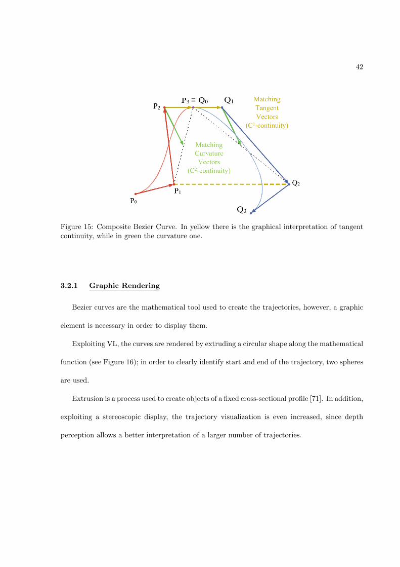
Figure 15 represents an example of two cubic Bezier curve composition.
42
Figure 15: Composite Bezier Curve. In yellow there is the graphical interpretation of tangentcontinuity, while in green the curvature one.
3.2.1 Graphic Rendering
Bezier curves are the mathematical tool used to create the trajectories, however, a graphic
element is necessary in order to display them.
Exploiting VL, the curves are rendered by extruding a circular shape along the mathematical
function (see Figure 16); in order to clearly identify start and end of the trajectory, two spheres
are used.
Extrusion is a process used to create objects of a fixed cross-sectional profile [71]. In addition,
exploiting a stereoscopic display, the trajectory visualization is even increased, since depth
perception allows a better interpretation of a larger number of trajectories.

43
Figure 16: Example of an extrusion from a circular shape along a Bezier curve. Start and endpoints are marked with spheres.
For this reason, an Extrusion class has been implemented in LACE Library. From this
point of view, VL improves the implementation consistently: since in QH only simple shapes
can be built, it would be really heavy computational trying to display such curves just by lines,
cylinders or series of points, thus slowing the overall program. However, in order to apply forces
consistently with the trajectory itself, it has been necessary to synchronize the two libraries.
LACE Extrusion is able to compute the Bezier needed just using the control points as
input. In particular, LACE implements automatically continuous Bezier, if needed, applying
continuity up to the second order. In this way, the variety of possible trajectory increases
consistently, since they will be longer (one, two or more extrusions), thus, also increasing the
overall task complexity.
The LACE Extrusion class structure enables both the creation of the extrusion itself, but
also insert graphics and haptics rendering of the control points by using spheres. In this way

44
the user can interact and have a better general view on how the control points have to be placed
to obtain a predetermined path.
3.3 Force Fields
Force fields are haptic applications belonging to the category of active constraints, or virtual
fixtures [14]. Generally, active constraint implementations are based on three main processes,
that, put together, give rise to the framework in Figure 17 [72].
Figure 17: General scheme of an active constraint implementation
The first process is the definition of the constraint itself. It creates the computational
representation, i.e. a geometry, of the constraint as output. The second stage allows the haptic
device to evaluate the constraint. Eventually, the regulation can be carried out as third stage:
here the software implementation is translated in hardware commands, so that the motion of
the trainee could be regulated and modified.

45
3.4 Implementation
Exploiting the great number of LACE functionalities, the psychomotor skill learning appli-
cation has been based on force field applied to spline curve trajectories. Since the user will
receive run-time haptic and visual feedback, WK library has been used, helping to avoid de-
lays. In this way, force computation is always fast and precise, and feelings among the two
main sensory modalities here taken into account, i.e. visual and tactile, are well matched.
The logic behind the overall implementation is showed in Figure 18: the application runs on
a Windows platform where the graphic and the haptic threads run concurrently, but at different
speeds (60 Hz for graphics and 1000 Hz for haptics).
The main elements are the trajectory and the cursor, both displayed visually and haptically.
The graphics rendering enables just the visualization of the two, while the haptic one combines
information provided by both of these objects in order to compute the distance from the closest
point on curve to the current cursor position, i.e. the haptic device one. The distance itself
represents the error computed by the trainee.
Since it is necessary to take into account also the time spent by the trainee to execute the
task, the Root Mean Square (RMS) error is saved at the end of every trajectory task, and
afterwards used for data analysis.
In the end, some predefined keyboard input are used to easily tune force field parameters
and study the effect of different applications.
In order to facilitate haptic dexterity, the mesh applied to the cursor has been chosen to
help the self-evaluation of the task: a hollow sphere, with slightly bigger dimensions than the

46
Figure 18: Psychomotor Skill scheme
extrusion shape, has been placed so to match its center with the tip of the haptic default
cursor. In this way, the user will carry out the task by having a clear visual feedback on his/her
performance, since a good task would be equal to have overlapped sphere and trajectory, as
displayed also in Figure 19.
An additional visual feedback has been implemented to further help the user during task
execution (Figure 20): depending on the error made, the trajectory will change color from
green, i.e. low or null error, to red, i.e. high error.

47
Figure 19: Cursor and Trajectory representation
3.4.1 Force Rendering
In this study, a linear 3-dimensional force field has been applied as function of the error
computed. In order to create these forces, it has been necessary to exploit the QH force callback,
along with WK library, so that the computation would be faster. Indeed, force callback is
executed at 1kHz, thus, a fast and reliable implementation is needed. The algorithm used is
represented in Figure 21.
When the “start sphere” is touched, the force callback starts. At this point all variables
used to compute the RMS Error are reset, too. As soon as the callback begins, the actual
cursor position is saved and used by WK library to compute the closest point on curve from an
external point in three dimension.
Since WK algorithm works only with single cubic Bezier, it is necessary to compute this
operation for all the extrusions that create the actual path. Once the function is called, WK
automatically generates the cubic curve, given the control points. Then it is divided into n
segments (1000 if not specified) and for each segment finds the closest point to the external

48
Figure 20: Representation of the trajectory’s change of color depending on cursor distance, i.e.the error made by the user. The more the cursor is away from the ideal curve, the more thetrajectory will move toward the red color.
point given. This operation is computed by knowing that a point on a line segment can be
parameterized by
P(t) = P0 + t(P1 −P0), t ∈ [0, 1] (3.13)
so that P0 and P1 are first and last points belonging to the segment itself (see also Figure 22).
Thus, ~P0P(b), i.e. the distance from the segment, is the projection of ~P0P onto ~P0P1.

49
Figure 21: Force Algorithm

50
Figure 22: Geometry representation of a distance froma linear segment. Using the scalarproduct among first and last point of the line segment, and the external point, the distance iscomputed.
In this way, it is possible to compute b as
b =d(P0,P(b))
d(P0,P1)=
~w • ~vL
~vL(3.14)
where ~w = P−P(b) and ~vL = P1 −P0.
Thus, as result,
d(P, ¯P1P0) = ‖P−P(b)‖ = ‖~w− (~w • ~vL)‖ (3.15)
Finding out the minimum distance among all the segments, the algorithm also reaches the
nearest point to the curve itself.

51
Once this point has been computed, the distance between it and the cursor position is
calculated and the force vector is built. This is characterized by magnitude equal to the distance
itself and direction equal to the one connecting the two points.
In addition, the force takes into account a gain so to amplify the force effect on the device;
indeed, distances are in the order of millimeters, thus, force feedback will be just slightly
perceived by the trainee. Depending on the force field applied, some parameters can vary and
are set in this step of the force callback.
Therefore, forces are computed as linear forces based on the following general equation:
~F = Gain ∗Distance ∗Direction (3.16)
Since they are magnified, and to not endanger the haptic device, a capping operation reduce
the maximum exerted force to 70% of the maximal nominal force (see Table II).
This linear approach has been used for both the Limit-Push and Limit-Trench condition.
In Figure 23 the force magnitude is shown as function of the distance. Here the aim is to give
only a qualitative representation of the forces trends.
• Limit-Push
Limit-Push condition studied by Sharp, I. et al. [59] is based on the application of a
step function. Here, it has been replaced with a ramp function, so that increasing the
error, also the force increases, proportionally to a certain slope. However, following the

52
Figure 23: Qualitative representation of forces as linear functions of the distance. Divergentforces are characterized by positive values, while convergent forces by negative ones; forcemagnitude is capped at a certain value FMax, which is 70% of the device Nominal Force. Ingreen are also showed the variable parameters that will be the subject of the test-bed study.
traditional concept, forces are applied only behind a certain distance threshold (Thr in
Figure).
• Limit-Trench
Since divergent forces can discourage the user in following the task, even if applied beyond
a safe region, also a new force field implementation is tested. In Limit-Trench the force
experienced by the trainee will be divergent near the trajectory, with a local maximum
exactly coincident with the ideal curve, and convergent when the distance from the tra-
jectory reaches a certain predefined threshold. In this way, it would be applied the same
concept of error augmentation, but without pushing too much on trainee ability to deal
and accept big errors.

53
As already said in 2, because different parameters, i.e. distance threshold and slope of the
straight line, can affect the overall experiment, and both of them are relevant in terms of haptic
feedback, which is the one we want to study as primary feedback, a preliminary study has been
prepared, creating a Test-bed version.
This first application has been implemented so as to try different threshold and gain (slope)
values. In this way, analyzing these preliminary data, the optimal parameters will be then used
in the real experimental phase.
3.5 Experimental Setup
The experimental setup is structured in different sections, as displayed in Figure 24, and
it is enriched with extra-features in order to be as flexible as possible in terms of trajectory
creation and slope and distance threshold values settings.
3.5.1 Choice of Trajectories
As soon as the application starts, the user can decide to train him/herself on default tra-
jectories or change them creating new ones. For this first implementation, it has been decided
to use a set of five different trajectories, allowing the same user to try different kinds of curves
in the trial.
Trajectory editing is carried out by directly moving the control points with the haptic device.
Since Bezier curves are splines, thus it would be difficult to exactly know its shape until it is
displayed, the curve variations are visible run-time. Of course, if multiple Bezier are connected
together, only some control points will be visible and usable, due to second order continuity
assessment. This task is automatically provided by the application.

54
Figure 24: Experimental Setup Workflow. First the user decided the trajectory to use, thenforce field is chosen and eventually the actual task can be carried out, editing the force functionparameters to optimally tune them.

55
3.5.2 Choice of Force Field
Once the trajectories are decided, the user can choose which kind of force fields he/she
wants applied. For testing purposes, also simple convergent and divergent force fields can be
used. The values of the different parameters are uploaded as default based on heuristic a priori
values, but they are modifiable during task execution.
3.5.3 Task Execution
Task execution is based on the algorithm shown in Figure 21. When the “start sphere” is
touched, its rapid change of color indicates the user that forces are on. When the end point is
reached, the RMS Error is displayed and the curve will be uploaded to the next available, if it
exists. Otherwise the task is completed.
Two different visuo-haptic feedback can be used to check and evaluate force strength, or to just
visually inform the user about his/her performance:
• Change of color in the trajectory : as explained in Section 3.4, depending on the run time
error computed by the user, i.e. the distance from the trajectory, the curve changes color
accordingly.
• Arrow Force visualization: this feature is not displayed by default, but it is possible
to turn it on or off via keyboard interaction. It enables the visualization of a qualitative
information of force under the form of an arrow. The magnitude is represented by changes
in dimension of the arrow, while direction as direction of the arrow itself (Figure 25). This
tool is also useful to debug the application and verify the correct force computation.

56
Figure 25: Force arrows visualization examples. In the upper trajectory, it is displayed a con-vergent force field, while a divergent one is represented in the lower curve.The arrow elongatesor shortens proportional to the force magnitude, pointing accordingly to the direction.
Also force parameters are changed via keyboard interactions:
• Slope setting can be changed by using up and down keyboard input. Editing this param-
eter, the force could be stronger or weaker, therefore, it is necessary taking into account
that also the capping will be performed earlier, i.e. nearer to the ideal path.
• Distance threshold is set by using left and right keyboard input. In this way, both Limit-
Push and Limit-Trench conditions can vary in terms of precision and overall ability re-
quired during task execution. However, the effects on trainee performances could be
different: in a Limit-Push set up, a lower threshold means higher error possibilities, thus
the user need to be more careful while performing. On the other hand, a lower threshold
in a Limit-Trench set up does not necessarily mean that the user has more error possi-

57
bilities due to lower divergent force application on the ideal trajectory and due to nearer
null force point application, i.e. nearer threshold.
Every time the user finishes a trajectory, the RMS Error is saved on a file.
3.5.4 Error Computation
Error computation is also explained in Figure 21, since its value is calculated along the force
computation. When the user starts to follow the trajectory, an artificial time counter starts
counting how many time the callback is executed. Then, at each cycle, the current error, i.e.
the run time distance, is summed to the total error, which is a variable that is updated by
summation at each callback event.
When the end point is touched, the actual error computation is carried out by simply
dividing the total error by the artificial timer:
RSMError =TotalError
ArtificialCounter(3.17)
RMS Error will be used to evaluate user performance, taking into account both accuracy
and time related aspects of the following-the-path task. Thus, it is possible to consider both
precision and velocity of the user.

CHAPTER 4
DISCUSSION
This work introduces the basis on which studies on psychomotor skill assessment can be
conducted: a Windows application has been presented, as solid start point analyzing the op-
timal haptic feedback parameters first, and the actual role of these feedback during training,
afterwards.
Integrating graphic and haptic elements, the platform is flexible and adequate to a large
variety of different implementations. Indeed, the core of the application itself, i.e. LACE
Library, can be used for virtual reality purposes in general, without being strictly bounded to
the biomedical field. Furthermore, it allows easily interface among virtual (haptic and graphic)
and physical (keyboard, mouse, and electromagnetic tracker) elements, and above all, new other
tools can be added and implemented.
The experimental setup can be considered as implementation of a general application for
skill assessment based on following-the-trajectory tasks. Haptic feedback are fundamental not
only in surgery, where tactile information are crucial to avoid tissue damages, but also in a
large number of different fields, especially in those involving the cooperation and/or interaction
with robotic elements. The possibility to actively communicate with the environment, through
a robot, could be vital where the situation is dangerous for direct intervention of human beings.
Focusing on the teleoperation field, no standard training protocols have been already defined.
However, all simulators provide non-surgical-related tasks training sections before allowing en-
58

59
tire procedure simulation. Indeed, it is necessary to learn how to efficiently control and manage
all the four daVinci arms, as well as coordinate feet and hands movements and tools activation
[51] before being able to manage entire procedures, thus, improve more specific surgical-related
skills. Considering also that no tactile information are given, learning how to properly deal
with objects (human tissues and organs in real life) can be challenging for both experts and
novices, at first glance.
For these reasons, this application is a fundamental step towards the assessment of an op-
timal and efficient surgical training tool. No major modification would affect the current tele-
operation way of working; instead, how physicians control the system would be revised. Haptic
feedback have been applied in rehabilitation with positive results; in particular error augmen-
tation and haptic disturbance seems promising to increase the training effects (see Chapter
2).
The truly potential of this application will be tested as experimental setup to assess two
main haptic feedback: Limit-Push and Limit-Trench. The former, has been successfully applied
in rehabilitation, for re-learning of daily tasks, and in motor learning as reshape movement tool
[59]; the latter is proposed here for the first time. The purpose and meaning of this new approach
has their basis in the Limit-Push concept: the feeling is that mistakes can bring frustration and
de-concentration to the trainee, thus not fully improving his/her skills. Applying a convergent
force when the error is too big, can be a further motivation for him/her to stay focus on the task
itself, increasing the overall performance. Howeer, the trickiness of this force field concept relies
in the maximal divergent force application exactly along the ideal trajectory (see Figure 23),

60
thus preventing the trainee to compute a perfect trial and challenging him/her more than what
he/she actually could expect.
In future works, these force fields will be first tuned so as to find the optimal force-gain and
distance-threshold parameters for training. Then, they will be validated in an actual training
protocol, verifying if their application improves or not skill learning. In this last stage of the
work, it could be useful to try to assess the new training protocol on an actual simulator,
comparing then the outcomes. In this way, the real difference in terms of training could be
evaluated. Instead of using a control group in the study, i.e. considering some trainees that
would carry out the training with no haptic feedback applied, it could be more meaningful to try
to assess a difference between the new proposed training protocol, and the actual way in which
surgeons train themselves on simulators. In particular, this could be especially meaningful with
the dVSS, since it uses the actual console available during surgeries.

APPENDICES
61

APPENDIX A
62

4/12/2017 RightsLink Your Account
https://s100.copyright.com/MyAccount/web/jsp/viewprintablelicensefrommyorders.jsp?ref=772fa6313c53467d90e655d5946483c0&email= 1/4
ELSEVIER LICENSETERMS AND CONDITIONS
Apr 12, 2017
This Agreement between Cecilia Gatti ("You") and Elsevier ("Elsevier") consists of your license details and the terms and conditionsprovided by Elsevier and Copyright Clearance Center.
License Number 4078541098420
License date Mar 29, 2017
Licensed Content Publisher Elsevier
Licensed ContentPublication
Clinical Biomechanics
Licensed Content Title Gait retraining to reduce lower extremity loading in runners
Licensed Content Author Harrison Philip Crowell,Irene S. Davis
Licensed Content Date January 2011
Licensed Content Volume 26
Licensed Content Issue 1
Licensed Content Pages 6
Start Page 78
End Page 83
Type of Use reuse in a thesis/dissertation
Portion figures/tables/illustrations
Number offigures/tables/illustrations
1
Format electronic
Are you the author of thisElsevier article?
No
Will you be translating? No
Order reference numberOriginal figure numbers Figure 3
Title of yourthesis/dissertation
Application of haptic virtual fixtures in psychomotor skill development for robotic surgical training
Expected completion date May 2017
Estimated size (number ofpages)
70
Elsevier VAT number GB 494 6272 12
Requestor Location Cecilia GattiVia Monteverdi 5
Novara, NO 28100ItalyAttn: Cecilia Gatti
Publisher Tax ID GB 494 6272 12
Total 0.00 USDTerms and Conditions
INTRODUCTION1. The publisher for this copyrighted material is Elsevier. By clicking "accept" in connection with completing this licensing transaction,you agree that the following terms and conditions apply to this transaction (along with the Billing and Payment terms and conditions
APPENDIX A
63

4/12/2017 RightsLink Your Account
https://s100.copyright.com/MyAccount/web/jsp/viewprintablelicensefrommyorders.jsp?ref=772fa6313c53467d90e655d5946483c0&email= 2/4
established by Copyright Clearance Center, Inc. ("CCC"), at the time that you opened your Rightslink account and that are availableat any time at http://myaccount.copyright.com).
GENERAL TERMS2. Elsevier hereby grants you permission to reproduce the aforementioned material subject to the terms and conditions indicated.3. Acknowledgement: If any part of the material to be used (for example, figures) has appeared in our publication with credit oracknowledgement to another source, permission must also be sought from that source. If such permission is not obtained then thatmaterial may not be included in your publication/copies. Suitable acknowledgement to the source must be made, either as a footnoteor in a reference list at the end of your publication, as follows:"Reprinted from Publication title, Vol /edition number, Author(s), Title of article / title of chapter, Pages No., Copyright (Year), withpermission from Elsevier [OR APPLICABLE SOCIETY COPYRIGHT OWNER]." Also Lancet special credit "Reprinted from TheLancet, Vol. number, Author(s), Title of article, Pages No., Copyright (Year), with permission from Elsevier."4. Reproduction of this material is confined to the purpose and/or media for which permission is hereby given.5. Altering/Modifying Material: Not Permitted. However figures and illustrations may be altered/adapted minimally to serve your work.Any other abbreviations, additions, deletions and/or any other alterations shall be made only with prior written authorization ofElsevier Ltd. (Please contact Elsevier at [email protected]). No modifications can be made to any Lancet figures/tables andthey must be reproduced in full.6. If the permission fee for the requested use of our material is waived in this instance, please be advised that your future requestsfor Elsevier materials may attract a fee.7. Reservation of Rights: Publisher reserves all rights not specifically granted in the combination of (i) the license details provided byyou and accepted in the course of this licensing transaction, (ii) these terms and conditions and (iii) CCC's Billing and Payment termsand conditions.8. License Contingent Upon Payment: While you may exercise the rights licensed immediately upon issuance of the license at theend of the licensing process for the transaction, provided that you have disclosed complete and accurate details of your proposeduse, no license is finally effective unless and until full payment is received from you (either by publisher or by CCC) as provided inCCC's Billing and Payment terms and conditions. If full payment is not received on a timely basis, then any license preliminarilygranted shall be deemed automatically revoked and shall be void as if never granted. Further, in the event that you breach any ofthese terms and conditions or any of CCC's Billing and Payment terms and conditions, the license is automatically revoked and shallbe void as if never granted. Use of materials as described in a revoked license, as well as any use of the materials beyond thescope of an unrevoked license, may constitute copyright infringement and publisher reserves the right to take any and all action toprotect its copyright in the materials.9. Warranties: Publisher makes no representations or warranties with respect to the licensed material.10. Indemnity: You hereby indemnify and agree to hold harmless publisher and CCC, and their respective officers, directors,employees and agents, from and against any and all claims arising out of your use of the licensed material other than as specificallyauthorized pursuant to this license.11. No Transfer of License: This license is personal to you and may not be sublicensed, assigned, or transferred by you to any otherperson without publisher's written permission.12. No Amendment Except in Writing: This license may not be amended except in a writing signed by both parties (or, in the case ofpublisher, by CCC on publisher's behalf).13. Objection to Contrary Terms: Publisher hereby objects to any terms contained in any purchase order, acknowledgment, checkendorsement or other writing prepared by you, which terms are inconsistent with these terms and conditions or CCC's Billing andPayment terms and conditions. These terms and conditions, together with CCC's Billing and Payment terms and conditions (whichare incorporated herein), comprise the entire agreement between you and publisher (and CCC) concerning this licensingtransaction. In the event of any conflict between your obligations established by these terms and conditions and those establishedby CCC's Billing and Payment terms and conditions, these terms and conditions shall control.14. Revocation: Elsevier or Copyright Clearance Center may deny the permissions described in this License at their sole discretion,for any reason or no reason, with a full refund payable to you. Notice of such denial will be made using the contact informationprovided by you. Failure to receive such notice will not alter or invalidate the denial. In no event will Elsevier or Copyright ClearanceCenter be responsible or liable for any costs, expenses or damage incurred by you as a result of a denial of your permission request,other than a refund of the amount(s) paid by you to Elsevier and/or Copyright Clearance Center for denied permissions.
LIMITED LICENSEThe following terms and conditions apply only to specific license types:15. Translation: This permission is granted for nonexclusive world English rights only unless your license was granted fortranslation rights. If you licensed translation rights you may only translate this content into the languages you requested. Aprofessional translator must perform all translations and reproduce the content word for word preserving the integrity of the article.16. Posting licensed content on any Website: The following terms and conditions apply as follows: Licensing material from anElsevier journal: All content posted to the web site must maintain the copyright information line on the bottom of each image; Ahypertext must be included to the Homepage of the journal from which you are licensing athttp://www.sciencedirect.com/science/journal/xxxxx or the Elsevier homepage for books at http://www.elsevier.com; Central Storage:This license does not include permission for a scanned version of the material to be stored in a central repository such as thatprovided by Heron/XanEdu.
APPENDIX A
64

4/12/2017 RightsLink Your Account
https://s100.copyright.com/MyAccount/web/jsp/viewprintablelicensefrommyorders.jsp?ref=772fa6313c53467d90e655d5946483c0&email= 3/4
Licensing material from an Elsevier book: A hypertext link must be included to the Elsevier homepage at http://www.elsevier.com .All content posted to the web site must maintain the copyright information line on the bottom of each image.
Posting licensed content on Electronic reserve: In addition to the above the following clauses are applicable: The web site mustbe passwordprotected and made available only to bona fide students registered on a relevant course. This permission is granted for1 year only. You may obtain a new license for future website posting.17. For journal authors: the following clauses are applicable in addition to the above:Preprints:A preprint is an author's own writeup of research results and analysis, it has not been peerreviewed, nor has it had any other valueadded to it by a publisher (such as formatting, copyright, technical enhancement etc.).Authors can share their preprints anywhere at any time. Preprints should not be added to or enhanced in any way in order to appearmore like, or to substitute for, the final versions of articles however authors can update their preprints on arXiv or RePEc with theirAccepted Author Manuscript (see below).If accepted for publication, we encourage authors to link from the preprint to their formal publication via its DOI. Millions ofresearchers have access to the formal publications on ScienceDirect, and so links will help users to find, access, cite and use thebest available version. Please note that Cell Press, The Lancet and some societyowned have different preprint policies. Informationon these policies is available on the journal homepage.Accepted Author Manuscripts: An accepted author manuscript is the manuscript of an article that has been accepted forpublication and which typically includes authorincorporated changes suggested during submission, peer review and editorauthorcommunications.Authors can share their accepted author manuscript:
immediatelyvia their noncommercial person homepage or blogby updating a preprint in arXiv or RePEc with the accepted manuscriptvia their research institute or institutional repository for internal institutional uses or as part of an invitationonlyresearch collaboration workgroupdirectly by providing copies to their students or to research collaborators for their personal usefor private scholarly sharing as part of an invitationonly work group on commercial sites with which Elsevier has anagreement
After the embargo periodvia noncommercial hosting platforms such as their institutional repositoryvia commercial sites with which Elsevier has an agreement
In all cases accepted manuscripts should:
link to the formal publication via its DOIbear a CCBYNCND license this is easy to doif aggregated with other manuscripts, for example in a repository or other site, be shared in alignment with our hosting policynot be added to or enhanced in any way to appear more like, or to substitute for, the published journal article.
Published journal article (JPA): A published journal article (PJA) is the definitive final record of published research that appears orwill appear in the journal and embodies all valueadding publishing activities including peer review coordination, copyediting,formatting, (if relevant) pagination and online enrichment.Policies for sharing publishing journal articles differ for subscription and gold open access articles:Subscription Articles: If you are an author, please share a link to your article rather than the fulltext. Millions of researchers haveaccess to the formal publications on ScienceDirect, and so links will help your users to find, access, cite, and use the best availableversion.Theses and dissertations which contain embedded PJAs as part of the formal submission can be posted publicly by the awardinginstitution with DOI links back to the formal publications on ScienceDirect.If you are affiliated with a library that subscribes to ScienceDirect you have additional private sharing rights for others' researchaccessed under that agreement. This includes use for classroom teaching and internal training at the institution (including use incourse packs and courseware programs), and inclusion of the article for grant funding purposes.Gold Open Access Articles: May be shared according to the authorselected enduser license and should contain a CrossMarklogo, the end user license, and a DOI link to the formal publication on ScienceDirect.Please refer to Elsevier's posting policy for further information.18. For book authors the following clauses are applicable in addition to the above: Authors are permitted to place a brief summaryof their work online only. You are not allowed to download and post the published electronic version of your chapter, nor may youscan the printed edition to create an electronic version. Posting to a repository: Authors are permitted to post a summary of theirchapter only in their institution's repository.19. Thesis/Dissertation: If your license is for use in a thesis/dissertation your thesis may be submitted to your institution in eitherprint or electronic form. Should your thesis be published commercially, please reapply for permission. These requirements include
APPENDIX A
65

4/12/2017 RightsLink Your Account
https://s100.copyright.com/MyAccount/web/jsp/viewprintablelicensefrommyorders.jsp?ref=772fa6313c53467d90e655d5946483c0&email= 4/4
permission for the Library and Archives of Canada to supply single copies, on demand, of the complete thesis and includepermission for Proquest/UMI to supply single copies, on demand, of the complete thesis. Should your thesis be publishedcommercially, please reapply for permission. Theses and dissertations which contain embedded PJAs as part of the formalsubmission can be posted publicly by the awarding institution with DOI links back to the formal publications on ScienceDirect. Elsevier Open Access Terms and ConditionsYou can publish open access with Elsevier in hundreds of open access journals or in nearly 2000 established subscription journalsthat support open access publishing. Permitted third party reuse of these open access articles is defined by the author's choice ofCreative Commons user license. See our open access license policy for more information.Terms & Conditions applicable to all Open Access articles published with Elsevier:Any reuse of the article must not represent the author as endorsing the adaptation of the article nor should the article be modified insuch a way as to damage the author's honour or reputation. If any changes have been made, such changes must be clearlyindicated.The author(s) must be appropriately credited and we ask that you include the end user license and a DOI link to the formalpublication on ScienceDirect.If any part of the material to be used (for example, figures) has appeared in our publication with credit or acknowledgement toanother source it is the responsibility of the user to ensure their reuse complies with the terms and conditions determined by therights holder.Additional Terms & Conditions applicable to each Creative Commons user license:CC BY: The CCBY license allows users to copy, to create extracts, abstracts and new works from the Article, to alter and revise theArticle and to make commercial use of the Article (including reuse and/or resale of the Article by commercial entities), provided theuser gives appropriate credit (with a link to the formal publication through the relevant DOI), provides a link to the license, indicates ifchanges were made and the licensor is not represented as endorsing the use made of the work. The full details of the license areavailable at http://creativecommons.org/licenses/by/4.0.CC BY NC SA: The CC BYNCSA license allows users to copy, to create extracts, abstracts and new works from the Article, to alterand revise the Article, provided this is not done for commercial purposes, and that the user gives appropriate credit (with a link to theformal publication through the relevant DOI), provides a link to the license, indicates if changes were made and the licensor is notrepresented as endorsing the use made of the work. Further, any new works must be made available on the same conditions. Thefull details of the license are available at http://creativecommons.org/licenses/byncsa/4.0.CC BY NC ND: The CC BYNCND license allows users to copy and distribute the Article, provided this is not done for commercialpurposes and further does not permit distribution of the Article if it is changed or edited in any way, and provided the user givesappropriate credit (with a link to the formal publication through the relevant DOI), provides a link to the license, and that the licensoris not represented as endorsing the use made of the work. The full details of the license are available athttp://creativecommons.org/licenses/byncnd/4.0. Any commercial reuse of Open Access articles published with a CC BY NC SA orCC BY NC ND license requires permission from Elsevier and will be subject to a fee.Commercial reuse includes:
Associating advertising with the full text of the ArticleCharging fees for document delivery or accessArticle aggregationSystematic distribution via email lists or share buttons
Posting or linking by commercial companies for use by customers of those companies. 20. Other Conditions: v1.9
Questions? [email protected] or +18552393415 (toll free in the US) or +19786462777.
APPENDIX A
66

4/14/2017 RightsLink Printable License
https://s100.copyright.com/AppDispatchServlet 1/4
WOLTERS KLUWER HEALTH, INC. LICENSETERMS AND CONDITIONS
Apr 14, 2017
This Agreement between Cecilia Gatti ("You") and Wolters Kluwer Health, Inc. ("WoltersKluwer Health, Inc.") consists of your license details and the terms and conditions providedby Wolters Kluwer Health, Inc. and Copyright Clearance Center.
License Number 4087980584985
License date Apr 14, 2017
Licensed Content Publisher Wolters Kluwer Health, Inc.
Licensed Content Publication Cancer Journal, The
Licensed Content Title Robotic Surgical Simulation
Licensed Content Author Michael Liss and Elspeth McDougall
Licensed Content Date Jan 1, 2013
Licensed Content Volume 19
Licensed Content Issue 2
Type of Use Dissertation/Thesis
Requestor type Individual
Portion Figures/table/illustration
Number offigures/tables/illustrations
1
Figures/tables/illustrationsused
Figure 1
Author of this WoltersKluwer article
No
Title of your thesis /dissertation
Application of haptic virtual fixtures in psychomotor skilldevelopment for robotic surgical training
Expected completion date May 2017
Estimated size(pages) 70
Requestor Location Cecilia GattiVia Monteverdi 5
Novara, NO 28100ItalyAttn: Cecilia Gatti
Publisher Tax ID EU826013006
Billing Type Invoice
Billing Address Cecilia GattiVia Monteverdi 5
Novara, Italy 28100Attn: Cecilia Gatti
Total 0.00 USD
Terms and Conditions
APPENDIX A
67

4/14/2017 RightsLink Printable License
https://s100.copyright.com/AppDispatchServlet 2/4
Wolters Kluwer Terms and Conditions
1. Transfer of License: Wolters Kluwer hereby grants you a nonexclusive license toreproduce this material for this purpose, and for no other use, subject to the conditionsherein.
2. Credit Line: will be prominently placed and include: For books – the author(s), title ofbook, editor, copyright holder, year of publication; For journals – the author(s), title ofarticle, title of journal, volume number, issue number, inclusive pages and website URL tothe journal page.
3. Warranties: The requestor warrants that the material shall not be used in any mannerwhich may be considered derogatory to the title, content, or authors of the material, or toWolters Kluwer.
4. Indemnity: You hereby indemnify and hold harmless Wolters Kluwer and their respectiveofficers, directors, employees and agents, from and against any and all claims, costs,proceeding or demands arising out of your unauthorized use of the Licensed Material.
5. Geographical Scope: Permission granted is nonexclusive, and is valid throughout theworld in the English language and the languages specified in your original request.
6. Wolters Kluwer cannot supply the requestor with the original artwork, electronic files or a"clean copy."
7. Permission is valid if the borrowed material is original to a Wolters Kluwer imprint(LippincottRaven Publishers, Williams & Wilkins, Lea & Febiger, Harwal, Rapid Science,Little Brown & Company, Harper & Row Medical, American Journal of Nursing Co, and Urban& Schwarzenberg English Language, Raven Press, Paul Hoeber, Springhouse, Ovid).
8. Termination of contract: If you opt not to use the material requested above please notifyRightsLink or Wolters Kluwer within 90 days of the original invoice date.
9. This permission does not apply to images that are credited to publications other thanWolters Kluwer books/journals or its Societies. For images credited to nonWolters Kluwerbooks or journals, you will need to obtain permission from the source referenced in thefigure or table legend or credit line before making any use of the image(s) or table(s).
10. Modifications: With the exception of text size or color, no Wolters Kluwer material ispermitted to be modified or adapted without publisher approval.
11. Third party material: Adaptations are protected by copyright, so if you would like toreuse material that we have adapted from another source, you will need not only ourpermission, but the permission of the rights holder of the original material. Similarly, if youwant to reuse an adaptation of original LWW content that appears in another publisherswork, you will need our permission and that of the next publisher. The adaptation should becredited as follows: Adapted with permission from Wolters Kluwer: Book author, title, yearof publication or Journal name, article author, title, reference citation, year of publication.Modifications are permitted on an occasional basis only and permission must be sought byWolters Kluwer.
12. Duration of the license: Permission is granted for a onetime use only within 12 monthsfrom the date of this invoice. Rights herein do not apply to future reproductions, editors,revisions, or other derivative works. Once the 12 month term has expired, permission torenew must be submitted in writing.
i. For content reused in another journal or book, in print or electronic format, thelicense is onetime use and lasts for the 1st edition of a book or for the life of theedition in case of journals.
ii. If your Permission Request is for use on a website (which is not a journal or a book),internet, intranet, or any publicly accessible site, you agree to remove the materialfrom such site after 12 months or else renew your permission request.
13. Contingent on payment: While you may exercise the rights licensed immediately uponissuance of the license at the end of the licensing process for the transaction, provided thatyou have disclosed complete and accurate details of your proposed use, no license is finallyeffective unless and until full payment is received from you (either by publisher or by CCC)as provided in CCC's Billing and Payment terms and conditions. If full payment is notreceived on a timely basis, then any license preliminarily granted shall be deemedautomatically revoked and shall be void as if never granted. Further, in the event that youbreach any of these terms and conditions or any of CCC's Billing and Payment terms andconditions, the license is automatically revoked and shall be void as if never granted. Useof materials as described in a revoked license, as well as any use of the materials beyondthe scope of an unrevoked license, may constitute copyright infringement and publisherreserves the right to take any and all action to protect its copyright in the materials.
APPENDIX A
68

4/14/2017 RightsLink Printable License
https://s100.copyright.com/AppDispatchServlet 3/4
14. Waived permission fee: If the permission fee for the requested use of our material hasbeen waived in this instance, please be advised that your future requests for WoltersKluwer materials may incur a fee.
15. Service Description for Content Services: Subject to these terms of use, any terms setforth on the particular order, and payment of the applicable fee, you may make thefollowing uses of the ordered materials:
i. Content Rental: You may access and view a single electronic copy of the materialsordered for the time period designated at the time the order is placed. Access to thematerials will be provided through a dedicated content viewer or other portal, andaccess will be discontinued upon expiration of the designated time period. An orderfor Content Rental does not include any rights to print, download, save, createadditional copies, to distribute or to reuse in any way the full text or parts of thematerials.
ii. Content Purchase: You may access and download a single electronic copy of thematerials ordered. Copies will be provided by email or by such other means aspublisher may make available from time to time. An order for Content Purchase doesnot include any rights to create additional copies or to distribute copies of thematerials.
For Journals Only:
1. Please note that articles in the aheadofprint stage of publication can be cited and thecontent may be reused by including the date of access and the unique DOI number. Anyfinal changes in manuscripts will be made at the time of print publication and will bereflected in the final electronic version of the issue. Disclaimer: Articles appearing in thePublished AheadofPrint section have been peerreviewed and accepted for publication inthe relevant journal and posted online before print publication. Articles appearing aspublish aheadofprint may contain statements, opinions, and information that have errorsin facts, figures, or interpretation. Accordingly, Wolters Kluwer, the editors and authors andtheir respective employees are not responsible or liable for the use of any such inaccurateor misleading data, opinion or information contained in the articles in this section.
2. Where a journal is being published by a learned society, the details of that society must beincluded in the credit line.
i. For Open Access journals: The following statement needs to be added whenreprinting the material in Open Access journals only: "promotional and commercialuse of the material in print, digital or mobile device format is prohibited without thepermission from the publisher Wolters Kluwer. Please [email protected] for further information."
ii. Exceptions: In case of reuse from Diseases of the Colon & Rectum, PlasticReconstructive Surgery, The Green Journal, Critical Care Medicine, PediatricCritical Care Medicine, the American Heart Association Publications and theAmerican Academy of Neurology the following guideline applies: no drug/ tradename or logo can be included in the same page as the material reused.
3. Translations: If granted permissions to republish a full text article in another language,Wolters Kluwer should be sent a copy of the translated PDF. Please include disclaimer belowon all translated copies:
i. Wolters Kluwer and its Societies take no responsibility for the accuracy ofthe translation from the published English original and are not liable for anyerrors which may occur.
4. Full Text Articles: Reuse of full text articles in English is prohibited.
STM Signatories Only:
1. Any permission granted for a particular edition will apply also to subsequent editions andfor editions in other languages, provided such editions are for the work as a whole in situand does not involve the separate exploitation of the permitted illustrations or excerpts.Please click here to view the STM guidelines.
Other Terms and Conditions:v1.17Questions? [email protected] or +18552393415 (toll free in the US) or
APPENDIX A
69

4/14/2017 RightsLink Printable License
https://s100.copyright.com/AppDispatchServlet 4/4
+19786462777.
APPENDIX A
70

71

72

CITED LITERATURE
1. Liss, M. A. and McDougall, E. M.: Robotic surgical simulation. The Cancer Journal,19(2):124–129, 2013.
2. Crowell, H. P. and Davis, I. S.: Gait retraining to reduce lower extremity loading in runners.Clinical biomechanics, 26(1):78–83, 2011.
3. Carter, B. N.: The fruition of halsted’s concept of surgical training. Surgery, 32(3):518–527,1952.
4. Kneebone, R.: Simulation in surgical training: educational issues and practical implica-tions. Medical education, 37(3):267–277, 2003.
5. Omalley, M. K., Celik, O., Huegel, J. C., Byrne, M. D., Bismuth, J., Dunkin, B. J., Goh,A. C., and Miles, B. J.: Robotics as a tool for training and assessment of surgicalskill. In Computational Surgery and Dual Training, pages 365–375. Springer, 2014.
6. Reznick, R. K. and MacRae, H.: Teaching surgical skillschanges in the wind. New EnglandJournal of Medicine, 355(25):2664–2669, 2006.
7. Gorman, P. J., Meier, A. H., and Krummel, T. M.: Simulation and virtual reality insurgical education: real or unreal? Archives of Surgery, 134(11):1203–1208, 1999.
8. Aboud, E. T., Krisht, A. F., O’keeffe, T., Nader, R., Hassan, M., Stevens, C. M., Ali, F.,and Luchette, F. A.: Novel simulation for training trauma surgeons. Journal ofTrauma and Acute Care Surgery, 71(6):1484–1490, 2011.
9. Davies, J., Khatib, M., and Bello, F.: Open surgical simulationa review. Journal of surgicaleducation, 70(5):618–627, 2013.
10. Liss, M. A. and McDougall, E. M.: Robotic surgical simulation. The Cancer Journal,19(2):124–129, 2013.
11. Williams, C. K. and Carnahan, H.: Motor learning perspectives on haptictraining for theupper extremities. IEEE transactions on haptics, 7(2):240–250, 2014.
73

74
CITED LITERATURE (continued)
12. Seymour, N. E.: Vr to or: a review of the evidence that virtual reality simulation improvesoperating room performance. World journal of surgery, 32(2):182–188, 2008.
13. Anderson, J. E., Chang, D. C., Parsons, J. K., and Talamini, M. A.: The first nationalexamination of outcomes and trends in robotic surgery in the united states. Journalof the American College of Surgeons, 215(1):107–114, 2012.
14. Okamura, A. M.: Methods for haptic feedback in teleoperated robot-assisted surgery.Industrial Robot: An International Journal, 31(6):499–508, 2004.
15. Maeso, S., Reza, M., Mayol, J. A., Blasco, J. A., Guerra, M., Andradas, E., and Plana,M. N.: Efficacy of the da vinci surgical system in abdominal surgery compared withthat of laparoscopy: a systematic review and meta-analysis, 2010.
16. Abboudi, H., Khan, M. S., Aboumarzouk, O., Guru, K. A., Challacombe, B., Dasgupta,P., and Ahmed, K.: Current status of validation for robotic surgery simulators–asystematic review. BJU international, 111(2):194–205, 2013.
17. McDougall, E. M.: Validation of surgical simulators. Journal of endourology, 21(3):244–247, 2007.
18. In American Heritage Dictionary of the English Language, ed. A. H. P. Company. Fifthedition, 2011.
19. Kelly, D. C., Margules, A. C., Kundavaram, C. R., Narins, H., Gomella, L. G., Trabulsi,E. J., and Lallas, C. D.: Face, content, and construct validation of the da vinciskills simulator. Urology, 79(5):1068–1072, 2012.
20. Hung, A. J., Patil, M. B., Zehnder, P., Cai, J., Ng, C. K., Aron, M., Gill, I. S., and Desai,M. M.: Concurrent and predictive validation of a novel robotic surgery simulator:a prospective, randomized study. The Journal of urology, 187(2):630–637, 2012.
21. Perrenot, C., Perez, M., Tran, N., Jehl, J.-P., Felblinger, J., Bresler, L., and Hubert, J.: Thevirtual reality simulator dv-trainer® is a valid assessment tool for robotic surgicalskills. Surgical endoscopy, 26(9):2587–2593, 2012.
22. Mimic Simulation. http://www.mimicsimulation.com/products/dv-trainer/. [Online;accessed 14-April-2017].

75
CITED LITERATURE (continued)
23. Seixas-Mikelus, S. A., Kesavadas, T., Srimathveeravalli, G., Chandrasekhar, R., Wilding,G. E., and Guru, K. A.: Face validation of a novel robotic surgical simulator.Urology, 76(2):357–360, 2010.
24. Seixas-Mikelus, S. A., Stegemann, A. P., Kesavadas, T., Srimathveeravalli, G., Sathyasee-lan, G., Chandrasekhar, R., Wilding, G. E., Peabody, J. O., and Guru, K. A.:Content validation of a novel robotic surgical simulator. BJU international,107(7):1130–1135, 2011.
25. Stegemann, A. P., Ahmed, K., Syed, J. R., Rehman, S., Ghani, K., Autorino, R., Sharif,M., Rao, A., Shi, Y., Wilding, G. E., et al.: Fundamental skills of robotic surgery: amulti-institutional randomized controlled trial for validation of a simulation-basedcurriculum. Urology, 81(4):767–774, 2013.
26. Whittaker, G., Aydin, A., Raison, N., Kum, F., Challacombe, B., Khan, M. S., Dasgupta,P., and Ahmed, K.: Validation of the robotix mentor robotic surgery simulator.Journal of Endourology, 30(3):338–346, 2016.
27. Minogue, J. and Jones, M. G.: Haptics in education: Exploring an untapped sensorymodality. Review of Educational Research, 76(3):317–348, 2006.
28. Hagen, M., Meehan, J., Inan, I., and Morel, P.: Visual clues act as a substitute for hapticfeedback in robotic surgery. Surgical endoscopy, 22(6):1505–1508, 2008.
29. Sann, C. and Streri, A.: Perception of object shape and texture in human newborns:evidence from cross-modal transfer tasks. Developmental Science, 10(3):399–410,2007.
30. Robles-De-La-Torre, G.: The importance of the sense of touch in virtual and real environ-ments. Ieee Multimedia, 13(3):24–30, 2006.
31. Holden, M. K.: Virtual environments for motor rehabilitation: review. Cyberpsychology& behavior, 8(3):187–211, 2005.
32. Judkins, T. N., Oleynikov, D., and Stergiou, N.: Enhanced robotic surgical training usingaugmented visual feedback. Surgical innovation, 15(1):59–68, 2008.
33. Hernandez, J., Bann, S., Munz, Y., Moorthy, K., Datta, V., Martin, S., Dosis, A., Bello,F., Darzi, A., and Rockall, T.: Qualitative and quantitative analysis of the learning

76
CITED LITERATURE (continued)
curve of a simulated surgical task on the da vinci system. Surgical Endoscopy AndOther Interventional Techniques, 18(3):372–378, 2004.
34. Schmidt, R. A. and Lee, T.: Motor control and learning. Human kinetics, 1988.
35. Heuer, H. and Luttgen, J.: Robot assistance of motor learning: A neuro-cognitive perspec-tive. Neuroscience & Biobehavioral Reviews, 56:222–240, 2015.
36. Georgopoulos, A. P.: Cognitive motor control: spatial and temporal aspects. Currentopinion in neurobiology, 12(6):678–683, 2002.
37. Halsband, U. and Lange, R. K.: Motor learning in man: a review of functional and clinicalstudies. Journal of Physiology-Paris, 99(4):414–424, 2006.
38. Gazzola, V., Rizzolatti, G., Wicker, B., and Keysers, C.: The anthropomorphic brain:the mirror neuron system responds to human and robotic actions. Neuroimage,35(4):1674–1684, 2007.
39. Hebb, D. O.: The organization of behavior: A neuropsychological theory. PsychologyPress, 2005.
40. Snoddy, G. S.: Learning and stability: a psychophysiological analysis of a case of motorlearning with clinical applications. Journal of Applied Psychology, 10(1):1, 1926.
41. Gentile, A. M.: A working model of skill acquisition with application to teaching. Quest,17(1):3–23, 1972.
42. Fitts, P. M. and Posner, M. I.: Human performance. 1967.
43. Anson, G., Elliott, D., and Davids, K.: Information processing and constraints-basedviews of skill acquisition: divergent or complementary? Motor control, 9(3):217–241, 2005.
44. Sigrist, R., Rauter, G., Riener, R., and Wolf, P.: Augmented visual, auditory, haptic, andmultimodal feedback in motor learning: a review. Psychonomic bulletin & review,20(1):21–53, 2013.
45. Okamura, A. M., Smaby, N., and Cutkosky, M. R.: An overview of dexterousmanipulation. In Robotics and Automation, 2000. Proceedings. ICRA’00. IEEEInternational Conference on, volume 1, pages 255–262. IEEE, 2000.

77
CITED LITERATURE (continued)
46. Bethea, B. T., Okamura, A. M., Kitagawa, M., Fitton, T. P., Cattaneo, S. M., Gott, V. L.,Baumgartner, W. A., and Yuh, D. D.: Application of haptic feedback to roboticsurgery. Journal of Laparoendoscopic & Advanced Surgical Techniques, 14(3):191–195, 2004.
47. Morris, D., Tan, H., Barbagli, F., Chang, T., and Salisbury, K.: Haptic feedback enhancesforce skill learning. In EuroHaptics Conference, 2007 and Symposium on HapticInterfaces for Virtual Environment and Teleoperator Systems. World Haptics
2007. Second Joint, pages 21–26. IEEE, 2007.
48. Wei, Y., Bajaj, P., Scheidt, R., and Patton, J.: Visual error augmentation for enhanc-ing motor learning and rehabilitative relearning. In Rehabilitation Robotics, 2005.ICORR 2005. 9th International Conference on, pages 505–510. IEEE, 2005.
49. Wulf, G., Shea, C. H., and Matschiner, S.: Frequent feedback enhances complex motorskill learning. Journal of motor behavior, 30(2):180–192, 1998.
50. Wagner, C., Stylopoulos, N., and Howe, R.: Force feedback in surgery: Analysis of bluntdissection. In Proceedings of the 10th symposium on haptic interfaces for virtualenvironment and teleoperator systems, 2002.
51. Smith, R., Truong, M., and Perez, M.: Comparative analysis of the functionality of simu-lators of the da vinci surgical robot. Surgical endoscopy, 29(4):972–983, 2015.
52. Patton, J. L., Stoykov, M. E., Kovic, M., and Mussa-Ivaldi, F. A.: Evaluation of robotictraining forces that either enhance or reduce error in chronic hemiparetic strokesurvivors. Experimental brain research, 168(3):368–383, 2006.
53. Lee, J. and Choi, S.: Effects of haptic guidance and disturbance on motor learning: Po-tential advantage of haptic disturbance. In Haptics Symposium, 2010 IEEE, pages335–342. IEEE, 2010.
54. Salmoni, A. W., Schmidt, R. A., and Walter, C. B.: Knowledge of results and motorlearning: a review and critical reappraisal. Psychological bulletin, 95(3):355, 1984.
55. Lee, H. and Choi, S.: Combining haptic guidance and haptic disturbance: an initialstudy of hybrid haptic assistance for virtual steering task. In Haptics Symposium(HAPTICS), 2014 IEEE, pages 159–165. IEEE, 2014.

78
CITED LITERATURE (continued)
56. Van der Meijden, O. and Schijven, M.: The value of haptic feedback in conventionaland robot-assisted minimal invasive surgery and virtual reality training: a currentreview. Surgical endoscopy, 23(6):1180–1190, 2009.
57. Bluteau, J., Coquillart, S., Payan, Y., and Gentaz, E.: Haptic guidance improves thevisuo-manual tracking of trajectories. PLoS One, 3(3):e1775, 2008.
58. Duschau-Wicke, A., von Zitzewitz, J., Caprez, A., Lunenburger, L., and Riener,R.: Path control: a method for patient-cooperative robot-aided gait reha-bilitation. IEEE Transactions on Neural Systems and Rehabilitation Engineering,18(1):38–48, 2010.
59. Sharp, I. and Patton, J. L.: Limit-push training reduces motor variability. InRehabilitation Robotics (ICORR), 2011 IEEE International Conference on, pages1–6. IEEE, 2011.
60. Faso, A.: Haptic and Virtual Reality Surgical Simulator for Training in Percutaneous RenalAccess. Master’s thesis, University of Illinois at Chicago, 2017.
61. Rapetti, L.: Virtual Reality Navigation System for Prostate Biopsy. Master’s thesis,University of Illinois at Chicago, 2017.
62. Tagliabue, E.: Visuo-Haptic Model of Prostate Cancer Based on Magnetic ResonanceElastography. Master’s thesis, University of Illinois at Chicago, 2017.
63. QuickHapticsTM MicroAPI. http://www.geomagic.com/it/products/open-haptics/
overview. [Online; accessed 14-April-2017].
64. Bosi, M.: Visualization Library. http://www.visualizationlibrary.org/, 2011. [Online;accessed 14-April-2017].
65. Partow, A.: Wykoby Computational Geometry Library. http://www.wykobi.com/index.html, 2005. [©2005-2017 Arash Partow. Online; accessed 14-April-2017].
66. Ascension Technology Corporation©. https://www.ascension-tech.com/products/.[Online; accessed 14-April-2017].
67. Kaufman, A.: Rendering, visualization and rasterization hardware. Springer Science &Business Media, 1993.

79
CITED LITERATURE (continued)
68. Salomon, D.: Curves and surfaces for computer graphics. Springer Science & BusinessMedia, 2007.
69. Bartels, R. H., Beatty, J. C., and Barsky, B. A.: An introduction to splines for use incomputer graphics and geometric modeling. Morgan Kaufmann, 1995.
70. Dodgson, N. A.: Some mathematical elements of graphics. 2000.
71. Oberg, E. V., Jones, F. D., and Horton, H. L.: Machinery’s handbook: a referencebook for the mechanical engineer, designer, manufacturing engineer, draftsman,toolmaker and machinist. Industrial Press, 1984.
72. Bowyer, S. A., Davies, B. L., and y Baena, F. R.: Active constraints/virtual fixtures: Asurvey. IEEE Transactions on Robotics, 30(1):138–157, 2014.
73. Rauter, G., von Zitzewitz, J., Duschau-Wicke, A., Vallery, H., and Riener,R.: A tendon-based parallel robot applied to motor learning in sports.In Biomedical Robotics and Biomechatronics (BioRob), 2010 3rd IEEE RAS andEMBS International Conference on, pages 82–87. IEEE, 2010.
74. Celnik, P., Webster, B., Glasser, D. M., and Cohen, L. G.: Effects of action observation onphysical training after stroke. Stroke, 39(6):1814–1820, 2008.
75. Levitan, R. M., Goldman, T. S., Bryan, D. A., Shofer, F., and Herlich, A.: Training withvideo imaging improves the initial intubation success rates of paramedic trainees inan operating room setting. Annals of emergency medicine, 37(1):46–50, 2001.
76. Blandin, Y., Toussaint, L., and Shea, C. H.: Specificity of practice: Interaction betweenconcurrent sensory information and terminal feedback. Journal of ExperimentalPsychology: Learning, Memory, and Cognition, 34(4):994, 2008.
77. Snodgrass, S. J., Rivett, D. A., Robertson, V. J., and Stojanovski, E.: Real-time feedbackimproves accuracy of manually applied forces during cervical spine mobilisation.Manual therapy, 15(1):19–25, 2010.
78. Scheidt, R. A., Reinkensmeyer, D. J., Conditt, M. A., Rymer, W. Z., and Mussa-Ivaldi,F. A.: Persistence of motor adaptation during constrained, multi-joint, arm move-ments. Journal of Neurophysiology, 84(2):853–862, 2000.

80
CITED LITERATURE (continued)
79. McVey, R., Goldenberg, M. G., Bernardini, M. Q., Yasufuku, K., Quereshy, F. A., Finelli,A., Pace, K. T., and Lee, J. Y.: Baseline laparoscopic skill may predict base-line robotic skill and early robotic surgery learning curve. Journal of Endourology,30(5):588–592, 2016.

I hereby authorize the use of my personal details solely for circulation within the company (Reference to Law 196/2003)
Curriculum Vitae: CECILIA GATTI
Surname, Name GATTI, CECILIA
Address VIA MONTEVERDI 5, 28100, NOVARA, ITALY
Telephone +39 3483689079
E-mail [email protected]
Nationality Italian
Date of birth 20TH APRIL, 1993
EDUCATION AND TRAINING
March 2016 - Today MSc in Bioengineering, University of Illinois, Chicago, USA.
September 2015 - Today MSc in Biomedical Engineering – Technologies for Electronics, Politecnico di Milano.
March 6th, 2017 Paper publication: Buzzi, J., Gatti, C., Ferrigno, G., De Momi, E., "Analysis of joint and
hand impedance during teleoperation and free-hand task execution" in IEEE Robotics &
Automation Letters, pages(s) 1-7. NearLab, Politecnico di Milano.
December 1st, 2016 Paper publication: Nessi, F., Beretta E., Gatti C., Ferrigno, G., De Momi, E., “Gesteme-
free context-aware adaptation of robot behavior in human–robot cooperation”, Artificial
Intelligence in Medicine, Elsevier. NearLab, Politecnico di Milano.
July 24th, 2015 Bachelor degree in Biomedical Engineering, Politecnico di Milano.
Dissertation: “Trajectory classification for surgeon’s activity recognition during
intraoperative robotic cooperation”. Tutor: Prof. Giancarlo Ferrigno
Final Course Grade: 106/110.
WORK EXPERIENCE
January 1st – April 30th, 2017 Research Graduate Fellow, Department of Urology – University of Illinois, Chicago, USA
October 2015 – July 2016 Collaborator at NearLab, Politecnico di Milano: research on musculoskeletal and dynamic
modelling of the surgeon arm during teleoperation.
Tutors: Prof. Giancarlo Ferrigno, Prof. Elena De Momi.
March – July 2015 Collaborator at NearLab, Politecnico di Milano: research on adaptive hands-on robot
behavior on a Kuka LWR4+ robotic arm.
Tutor: Prof. Giancarlo Ferrigno
March - July 2014 Development of an electromyography device (optional project-assignment of the
“Informatica ed Elementi di Informatica Medica” course) carried out in collaboration with
Necst Lab, Politecnico di Milano.
Tutor: Prof. Marco D. Santambrogio.
LANGUAGES Fluent in English and Italian
COMPUTER SKILLS
AND COMPETENCES
OPERATING SYSTEMS: Windows, Linux (Ubuntu 14.04LTS).
SOFTWARE: academic knowledge of Microsoft Office; academic knowledge of
MATLAB (MathWorks Inc.), RStudio IDE (Rstudio Inc.), OpenSim software (Sun
Microsystems Inc.); basic use of VolView (Kitware Inc.), ParaView, itk-SNAP.
PROGRAMMING LANGUAGES: C/C++.
ADDITIONAL INFORMATION AAAS (American Association for the Advancement of Science) Member, ID:20347048
IEEE (Institute of Electrical and Electronics Engineers) Student Member, ID: 94222758
VITA
81