APPLICATION OF DIAGNOSTICS AS A BASIS OF CONDITION …
16
Brodogradnja/Shipbuilding/Open access Volume 71 Number 3, 2020 119 Cvrk Sead Ilijević Dragan http://dx.doi.org/10.21278/brod71307 ISSN 0007-215X eISSN 1845-5859 APPLICATION OF DIAGNOSTICS AS A BASIS OF CONDITION BASED MAINTENANCE OF THE MARINE PROPULSION DIESEL ENGINE UDC 621.436.13 Professional paper Summary This paper is about condition based maintenance and technical diagnostic on specifically object-cylinder units of two stroke low speed diesel engine MAN B&W 8K80MC-C. It describes: the way of controlling direct parameters (pressure and temperature) taken from the engine, measuring the pressure in engine cylinders via electronic device "PREMET" and visual control of cylinder liners and pistons. Analyzing the data we got clear conclusion about needs of preventive action or possibility of extension of exploitation without maintenance for certain period. Practice confirms that it is possible to extend the period between two overhauls while maintaining engine performance within the limits prescribed by the manufacturer and the values of the parameters obtained on the test drive, as well as reduce maintenance costs. Key words: ship; cylinder unit; measuring equipment; technical education; competence 1. Introduction The main marine propulsion engine's performance is determined by operational safety, protection of the environment, reliability and price. The purpose of modern maintenance is to maintain the designed reliability, availability and degree of efficiency of the marine propulsion engine at the lowest possible cost. Proper and long-lasting functioning of the engine depends on its proper maintenance. Unplanned stagnation and breakdowns, which can result from improper maintenance, can create additional costs. By implementing Condition Based Maintenance, the failure can be predicted, and the period of the planned overhaul can be extended. The intervention is performed after the signal is obtained by analysis of individual parameters that are constantly monitored. On the basis of the symptoms that are obtained by monitoring the parameters, the diagnosis of the condition is given and the intervention is performed if necessary. The validity of such a maintenance system depends on the validity of the information we obtain by measuring. There is also a need for increased reliability of diagnosis. This is achieved by the quality of diagnostic instruments, the training of those who perform measurements and the systematic examination. The term of intervention or repair of the device is determined based on the performed diagnostics. [1, 2].
Transcript of APPLICATION OF DIAGNOSTICS AS A BASIS OF CONDITION …

Brodogradnja/Shipbuilding/Open access Volume 71 Number 3, 2020
119
Cvrk Sead
Ilijević Dragan
http://dx.doi.org/10.21278/brod71307 ISSN 0007-215X
eISSN 1845-5859
APPLICATION OF DIAGNOSTICS AS A BASIS OF CONDITION
BASED MAINTENANCE OF THE MARINE PROPULSION DIESEL
ENGINE
UDC 621.436.13
Professional paper
Summary
This paper is about condition based maintenance and technical diagnostic on specifically
object-cylinder units of two stroke low speed diesel engine MAN B&W 8K80MC-C. It
describes: the way of controlling direct parameters (pressure and temperature) taken from the
engine, measuring the pressure in engine cylinders via electronic device "PREMET" and
visual control of cylinder liners and pistons. Analyzing the data we got clear conclusion about
needs of preventive action or possibility of extension of exploitation without maintenance for
certain period. Practice confirms that it is possible to extend the period between two overhauls
while maintaining engine performance within the limits prescribed by the manufacturer and
the values of the parameters obtained on the test drive, as well as reduce maintenance costs.
Key words: ship; cylinder unit; measuring equipment; technical education; competence
1. Introduction
The main marine propulsion engine's performance is determined by operational safety,
protection of the environment, reliability and price. The purpose of modern maintenance is to
maintain the designed reliability, availability and degree of efficiency of the marine
propulsion engine at the lowest possible cost. Proper and long-lasting functioning of the
engine depends on its proper maintenance. Unplanned stagnation and breakdowns, which can
result from improper maintenance, can create additional costs. By implementing Condition
Based Maintenance, the failure can be predicted, and the period of the planned overhaul can
be extended. The intervention is performed after the signal is obtained by analysis of
individual parameters that are constantly monitored. On the basis of the symptoms that are
obtained by monitoring the parameters, the diagnosis of the condition is given and the
intervention is performed if necessary. The validity of such a maintenance system depends on
the validity of the information we obtain by measuring. There is also a need for increased
reliability of diagnosis. This is achieved by the quality of diagnostic instruments, the training
of those who perform measurements and the systematic examination. The term of intervention
or repair of the device is determined based on the performed diagnostics. [1, 2].

Sead Cvrk Application of dijagnostics as a basis of maintenance
Dragan Ilijević according to the condition of the main marine diesel engine
120
This paper is based on concrete results obtained during the three-year exploitation of the
main two-stroke engine "MAN B&W 8K80 MC-C" on the ship "HS SCOTT" of the German
company "HANSA SHIPPING". The ship has a computer program "TITAN" for planning
preventive maintenance of ship systems based on working hours or time period depending on
the type of system. This program also includes the maintenance of the marine propulsion
engine with all its subsystems. According to the manufacturer's recommendation, each
subsystem of the main marine propulsion engine must be repaired after a certain number of
working hours. Thus, the overhaul of cylinder units is recommended after a period of 16000
working hours [3]. By implementing Condition Based Maintenance and using technical
diagnostics in the control of the main propulsion engine, beginning of the overhaul of the first
cylinder unit was postponed to 20637 working hours, and the last cylinder unit was
overhauled after 26876 working hours. Modern diagnostic systems, despite being equipped
with modern technical and technological solutions, usually only inform engineers about the
values of the tested parameters. Based on this information, and primarily on the conclusions
obtained after the visual inspection of the condition of the cylinder liners and piston rings,
conclusions were made about the need to overhaul the cylinder unit. It is important to point
out that during the entire period, the ship performed its tasks without downtime, which is very
important for the shipowner in terms of earnings. Engine performance and specific fuel
consumption did not differ significantly from the values obtained during the test run of the
test vessel, and the emission were fully kept within the standardized limits.
2. Experience and achievements of MAN B&W in Condition Based Maintenance of
engine cylinder units
MAN B&W is one of the leading manufacturers of two-stroke low-speed engines in the
world. They have designed a two-stroke engine that fully meets the requirements and
regulations set before the maritime industry. This implies cooperation with maritime
authorities, governments and international organizations in the improvement and
implementation of new rules, all with the aim of reducing the emission of harmful exhaust
gases by realistic methods. The aim is to achieve a method that will be suitable and practical
for marine use and that will be implemented with a high degree of engine safety and
reliability. On the other hand, customer requirements, in addition to reducing the emission of
harmful gases into the atmosphere, are also the reduction of specific fuel consumption at
different engine loads as well as the extension of the time between two overhauls [3].
In addition to many new technical solutions and innovations that have been applied on
the new series of MC and ME engines, Condition Based Maintenance with the application of
technical diagnostics has also been applied. Data obtained from ships on which a Condition
Based Maintenance was used with the application of technical diagnostics show that the
average time between two overhauls is 32000 working hours [3]. This is very favorable for
tanker and container maritime traffic because it opens the possibility for repairs to be done in
the docking every five years. This method of maintenance is greatly helped by the use of
modern electronic devices for monitoring parameters and diagnostics. Depending on the MC
or ME engine series, MAN B&W has produced two types of electronic devices. For the MC
series engines, a PMI (Pressure Mean Indicator) pressure analyzer was produced, and for the
ME series engines, a special hardware-software system CoCoS-EDS (Computer Controlled
Surveillance-Engine Diagnostics System) [4, 5].

Application of dijagnostics as a basis of condition based Sead Cvrk
maintenance of the marine propulsion diesel engine Dragan Ilijević
121
2.1 PMI for two-stroke low-speed MC series marine diesel engines
For MC series engines, MAN B&W has produced a PMI pressure analyzer to measure
all relevant parameters in the engine cylinder during combustion [3]. PMI is a computerized
device for reliable and accurate performance calculation of two-stroke and four-stroke
engines. The device replaces the conventional device for measuring the changes in pressure in
the engine cylinder during the cycle, and also does not require a planimeter and manual
calculation of engine power. This device uses a high quality piezo-electric pressure sensor and
can automatically identify on which cylinder the pressure is being measured. After recording
the performance, the data from the PMI analyzer is transferred to the computer for data
analysis [4].
Figure 1 shows the elements of the PMI system for measuring the change in pressure in
the engine cylinder during the cycle.
Figure 1. Elements of the PMI system for measuring the pressure in the engine cylinder [3]
2.2 CoCoS-EDS for two-stroke low-speed MC series marine diesel engines
The MC series low-speed two-stroke chain drive engines for camshaft operation have
limited flexibility when activating the injectors and exhaust valves, and these are two
important factors for achieving optimal engine performance. In contrast, ME engines use a
hydraulic-mechanical system to activate injectors and exhaust valves. The actuators are
electronically controlled with a number of control devices, which complete the engine control
system.
MAN B&W has developed a special hardware-software system for engine control of the
ME series called CoCoS-EDS [5], which enables increased monitoring and planning of
engine maintenance. In fact, there are four software programs.
The CoCoS-EDS program includes data storage, monitoring and diagnostics. If there is
a deviation from the set performance or a malfunction, the possibility of the cause of the

Sead Cvrk Application of dijagnostics as a basis of maintenance
Dragan Ilijević according to the condition of the main marine diesel engine
122
malfunction will be obtained, as well as actions that should be taken to eliminate the
malfunction.
Figure 2. Elements of the CoCoS-EDS system [5]
2.3 LDM device for measuring the diameter of the engine cylinder liner
Insight into the condition of the cylinder liners is very important. The measurement of
the wear of the liners is performed regularly when removing the piston. In order to measure
the diameter of the cylinder liner with a conventional internal micrometer, it is necessary to
dismantle the head from the cylinder unit or the exhaust valve. MAN B&W has also included
LDM (Liner Diameter Measuring Instrument) in diagnostic devices. It is not necessary to lift
the cylinder head or the exhaust valve using an LDM. The device is installed through the
scavenging air openings of the cylinder liner which are reached through the scavenging air
collector.

Application of dijagnostics as a basis of condition based Sead Cvrk
maintenance of the marine propulsion diesel engine Dragan Ilijević
123
Figure 3. Cylinder liner diameter measurement procedure with LDM device [5]
The LDM device is designed for precise measurement of the diameter of the cylinder
liner. It consists of:
- Measuring unit that is mounted inside the cylinder liner on the piston head. The
measured values are sent through radio signal via an antenna that is mounted in
place of the air start valve. The antenna is connected to the interface box via a cable.
- A device for measuring the vertical position of the piston, which is placed under the
piston with the help of a magnet and is connected to the interface box with a cable.
- The interface box which has two input signals, an antenna and a device for
measuring the vertical position of the piston and one output signal connecting box to
a computer via bluetooth.
- A computer where data is stored and can be transferred to Excel, on a personal
computer via bluetooth, USB or SD card.
The average measurement time per cylinder unit is about one hour, with four
measurements of the cylinder liner diameter at nine different heights. The accuracy of the
device is 0,03 mm. This device can be applied to cylinder liners with a diameter of 500 to 980
mm [6]. Due to the high cost of the device, most ships still use the conventional method of
measurement using an internal micrometer. The conventional method of measurement
primarily depends on the training and experience of the person performing the measurement,
so the possibility of error is high.
3. Subject of research
The research was conducted on the cylinder units of the main two-stroke low-speed
marine diesel engine MAN B&W 8K80 MC-C.
Table 1: Technical data for the engine [7]
Engine
manufacturer
Engine
model
Working
principle
Maximum
power
Number of
cylinders Bore/Stroke
MAN B&W 8K80 MC-C Two-stroke
reversible
28880 [kW]
104 [min-1] 8
800 [mm]
2300 [mm]
During engine exploitation, engine parameters were monitored and recorded at certain
time intervals. Continuous control of parameters is necessary in order to detect certain
changes in [7]:

Sead Cvrk Application of dijagnostics as a basis of maintenance
Dragan Ilijević according to the condition of the main marine diesel engine
124
- combustion process,
- the general physical condition of the cylinder units
- general changes in engine operation.
The control of operating parameters is done in order to keep the performance of the
engine within the set limits. Timely detection of these changes enables preventive measures to
be taken and accidents to be prevented.
The key parameters for determining the engine performance are [7]:
- barometric ambient pressure,
- speed of the ship,
- ship's draught,
- mean indicated pressure,
- compression pressure,
- maximum combustion pressure,
- high fuel pressure pump index,
- exhaust pressures,
- exhaust temperatures,
- scavenging air pressure,
- scavenging air temperature,
- turbocharger rotational speed,
- exhaust gas pressure in the exhaust line after the turbocharger,
- air temperature at the turbocharger intake,
- pressure difference in front of and behind the intake air filter,
- pressure difference in front and behind the air cooler and
- air and cooling water temperature before and after the scavenging air cooler.
The intervals between controls were defined as permanent, daily and monthly. Pressures
and temperatures must be constantly monitored to protect the engine from overheating and
malfunction. For this purpose, the system for remote control and monitoring of the engine
"Auto Chief C20" is used. Daily controls include all parameters that affect engine
performance and their records are noted in the machine log. Monthly control is performed for
all parameters that affect engine performance, by measuring the pressure in the engine
cylinder using the electronic system PREMET XL as well as visual control of cylinder liners
and pistons through the scavenging air receiver. When it comes to engine performance,
special attention must be paid to the following indicators [7]:
- directly measurable indicators,
- indirectly measurable indicators,
- hidden indicators and
- ISO correction.
Directly measurable indicators are pressures and temperatures that we read on the
engine itself using built-in thermometers and manometers. It is very important that the
measuring instruments are correct and calibrated in order to obtain reliable data. Figure 4
shows the measuring points on the motor where the measuring instruments are located or the
possible places for their connection [7].

Application of dijagnostics as a basis of condition based Sead Cvrk
maintenance of the marine propulsion diesel engine Dragan Ilijević
125
Figure 4. Measuring points of directly measurable parameters on the engine [7]
Figure 4 shows the measuring points of the following engine parameters:
- indicator valve for measuring the pressure in the engine cylinder position 1,
- fuel index lever and VIT index position 2,
- exhaust gas temperature at the outlet of the cylinder position 3,
- exhaust gas temperature before and after the turbocharger position 4,
- exhaust gas pressure after turbocharger position 5,
- exhaust pressure in the exhaust manifold position 6,
- air temperature at the inlet to the turbocharger position 7,
- air pressure at the turbocharger intake intake position 8,
- chiller air pressure drop position 9,
- water temperature at the inlet and outlet of the air cooler position 10,
- scavenging air pressure in the manifold position 11,
- scavenging air temperature in the collector position 12,
- scavenging air temperature before cooler position 13,
- scavenging air temperature after cooler position 14 and
- engine coolant outlet temperature position 15.
In addition to the above parameters, other data that is taken with directly measurable
parameters are [7]:
- engine rotational speed,
- turbocharger rotational speed,
- fuel pressure,
- fuel temperature at the engine inlet,
- coolant temperature at engine inlet and
- barometric ambient pressure.
Indirectly measurable indicators are pressure measurings done during operation of the
cylinder engine. To measure the pressures in the engine cylinder and record the diagram, the

Sead Cvrk Application of dijagnostics as a basis of maintenance
Dragan Ilijević according to the condition of the main marine diesel engine
126
electronic system PREMET XL was used, whose function is identical to the system of the
PMI pressure analyzer. This system allows us, in addition to the maximum combustion
pressure, to determine the average indicator pressure, compression pressure, indicator power
and the relationship between the crank rotation angle and the pressure. The PREMET XL
system has a computer where the analysis of recorded data is performed with the help of
installed software. Before the data analysis, the software allows us to enter additional
information, such as: exhaust gas temperature, position of the high pressure fuel pump rails,
injection angle and rotational speed of the turbocharger rotor. As well as the data needed for
ISO correction, such as engine coolant temperature, compressor inlet air temperature, specific
fuel density, fuel calorific value and engine inlet temperature. After entering the data, the
process of analysis begins. The following diagrams are displayed on the computer screen: p/α
diagram for all cylinders, p/α diagram including dp/dα curve for each cylinder, zoomed p/α
diagram including dp/dα curve for each cylinder, p/V diagram of all cylinders, p/V single
cylinder diagram, pmax for all measured strokes on one cylinder, pmax for all strokes and all
cylinders, mean pmax for all cylinders, indicator pressure diagram for all cylinders, mean
indicated pressure diagram for all cylinders, mean indicated deviation diagram pressure, a
diagram of the deviation of the indicated power and finally a tabular presentation of
completed data.
Even if direct and indirect indicators are within limits, it does not necessarily mean that
the engine is operating in the optimum load range. The problem can occur when the engine
crankshaft is raised again from the lower rotational speed to the nominal speed. In the event
of maximum combustion pressure, exhaust gas temperature before and after the turbocharger,
turbocharger rotational speed, flush air pressure and fuel index increase, attention must be
paid to the thermal load of the engine. Even if the engine is regularly maintained and working
flawlessly, it can easily be overloaded resulting in inevitably damage the cylinder liner in a
very short period of time. The main causes of thermal overload are mainly the hidden factors,
such as:
- overgrown formwork of broad and propeller wings,
- distorted or damaged propeller blades,
- heavy sea and
- shallow water on the navigation route.
In order to avoid the influence of hidden factors on the thermal and mechanical overload
of the engine, it is necessary:
- to calculate the effective engine power and the mean effective pressure at a specific
crankshaft rotational speed, and
- to calculate the slip of the ship's propeller.
When the specified parameters are determined, operating mode is checked in relation to
the defined limits on the motor load diagram.
ISO corrections are calculated based on known formulas and take into account the
influence of inlet air and engine coolant temperatures on exhaust gas temperature, scavenging
air pressure, compression pressure and maximum combustion pressure. ISO corrections must
be made when the intake air and coolant temperatures at the engine inlet are significantly
higher than 25 ºC. After the corrections are made, the obtained results can be compared with
the data from the previous measurements and the data when the engine was tested in the test
drive of the new engine. Based on these data, an insight into the condition of the engine is
obtained [7].

Application of dijagnostics as a basis of condition based Sead Cvrk
maintenance of the marine propulsion diesel engine Dragan Ilijević
127
In addition to monitoring all the above parameters, one of the important measures for
the application of the principle of Condition Based Maintenance is the visual control of the
cylinder liners and pistons through the scavenging air collector. The physical condition of the
piston rings is very important. The role of the piston rings is to provide a seal between the
piston and the liner with the help of gases in the cylinder, in order to prevent the penetration
of gases from the combustion chamber into the cylinder space under the piston. This sealing is
achieved by the action of gases from the upper and inner side of the piston ring, which results
in pushing the piston ring towards the lower side of the groove in the piston and outside
towards the wall of the cylinder liner [8]. Timely detection of changes in the cylinder liners
and pistons can prevent large-scale accidents, but also if the condition is found to be
satisfactory, the overhaul of the cylinder units can be postponed. During the visual control of
the cylinder units, an important factor is the experience of the crew, their consistency and
thorough inspection as well as accurate recording of the obtained results. It is recommended
that the control of the cylinder units, if possible, be done immediately after a long voyage by
stopping the ship before entering the port. This is essential to avoid the impact of low engine
operation loads during ship maneuvering. At low loads, the lubrication of the cylinder liners is
increased, which can give a wrong picture of the estimated amount of oil for lubricating the
cylinder liners. Another reason is the combustion in the cylinder, which is not optimal at low
loads and can give a wrong picture of the condition of the piston head and piston rings.
4. Presentation of data obtained by recording engine performance in the period from
March 2009 to March 2012 with discussion
A total of 12 measurements were performed and than presented in tables, on the basis of
which a comparison of measured parameters, analysis and conclusions were made. It should
be emphasized that the sailing conditions of the ship for each measurement were different
(meteorological conditions, the state of the ship's hull and the state of the sea). The sailing
conditions of the ship were also differed in relation to the measurements performed in the test
run after the construction of the ship.
Table 2. Pressures in the engine cylinder obtained by the electronic device PREMET XL [9]
Date
measur-
ements
Crankshaft
rotational
speed
[min-1]
Maximum
compression
pressure
pkmax [bar]
Maximal
combustion
pressure
psmax [bar]
Mean
indicated
pressure
psi [bar]
Average
indicator
power
Psi [kW]
Medium
temperature
exhaust
gases
Tsizg [ºC]
26.03.09 102.0 100.0 116.1 14.1 22078 333.5
18.05.09 103.5 106.0 119.9 15.5 24739 330.0
18.11.09 103.4 99.4 109.0 14.3 22720 349.4
13.02.10 103.6 104.0 115.9 14.8 23705 333.3
21.06.10 103.4 106.2 116.4 15.3 24420 328.1
22.11.10 103.4 107.9 117.4 15.6 24864 341.0
20.01.11 103.6 107.9 118.4 15.8 25172 357.1
14.06.11 103.5 105.5 115.8 15.2 24170 341.8
26.09.11 103.7 105.1 115.8 15.4 24748 342.9
20.12.11 104.0 103.5 113.6 14.8 23746 352.9
17.01.12 103.8 102.2 113.0 15.1 24207 350.3
13.03.12 103.3 102.9 112.8 15.1 24452 339.3

Sead Cvrk Application of dijagnostics as a basis of maintenance
Dragan Ilijević according to the condition of the main marine diesel engine
128
Table 3. Scavenging air parameters [9]
Date
measur-
ements
Turbocharger
rotational
speed
1/2 [min-1]
Temperature
Scaveng-
ing air
pressure
pisv [bar]
Air at the
compressor
inlet
Tvauk [ºC]
Water at
the inlet to
the cooler
Tvour [ºC]
Air on
inlet to the
cooler 1/2
Tvaur [ºC]
Air on
out of the
cooler 1/2
Tvair [ºC]
26.03.09 11120/11100 30 36 151/152 38/38 2.00
18.05.09 11613/11566 41 40 180/170 42/42 2.20
18.11.09 11244/11201 41 34 185/185 39/40 2.00
13.02.10 11320/11324 36 36 165/175 41/40 2.11
21.06.10 11636/11638 41 38 180/84 44/43 2.20
22.11.10 11580/11610 41 38 180/85 44/44 2.20
20.01.11 11708/11714 41 38 179/181 43/43 2.20
14.06.11 11627/11629 42 36 180/85 44/42 2.40
26.09.11 11580/11600 42 36 180/185 44/44 2.20
20.12.11 11460/11460 40 37 180/180 44/44 2.10
17.01.12 11390/11415 42 39 177/180 44/44 2.10
13.03.12 11420/11450 40 38 175/180 44/44 2.10
Table 4. ISO corrections of pressures and temperatures of combustion products [9]
Date
measur-
ements
ISO corrected
scavenging air
pressure
pisp [bar]
ISO corrected
compression
pressure
pkom [bar]
ISO corrected
maximum
pressure
pmax [bar]
ISO corrected
scavenging air
temperature
Tisv [ºC]
26.03.09. 1.97 99.8 116.9 322.2
18.05.09. 2.24 108.6 122.8 301.6
18.11.09. 2.08 102.8 111.4 321.4
13.02.10. 2.13 105.6 117.7 313.0
21.06.10. 2.25 109.1 119.0 300.0
22.11.10. 2.24 110.6 119.9 313.8
20.01.11. 2.25 110.9 121.1 327.6
14.06.11. 2.48 109.6 118.6 312.0
26.09.11. 2.28 108.6 118.6 313.3
20.12.11. 2.15 106.2 116.0 325.5
17.01.12. 2.10 105.2 115.7 319.2
13.03.12. 2.10 105.4 115.2 312.1
Tables 2, 3 and 4 show the parameters that characterize the combustion process. It can
be observed that all parameters are measured at the engine rotational speed for maximum
power when testing the engine on the brake. At this crankshaft rotational speed, the engine
will develop a different power for each measurement depending on the sailing conditions,
displacement, overgrowth of the ship's hull and some other less important factors. All
parameters are within the set limits and differ slightly from those measured in the test run of
the ship after the construction. Due to the high temperatures of the scavenging air at the inlet
to the compressor and the cooling water at the inlet to the flue air cooler, ISO correction of
the scavenging air pressure, compression pressure, maximum combustion pressure and
scavenging air temperature was performed.

Application of dijagnostics as a basis of condition based Sead Cvrk
maintenance of the marine propulsion diesel engine Dragan Ilijević
129
Table 5. Deviations from the measured mean values in % [9]
Table 5 shows the deviations of the indicator pressure, maximum combustion pressure
and scavenging air temperature in relation to the measured mean values. It can be noticed that
the deviations did not vary more than 5 %, which is allowed for this engine, and this also
indicates that the engine worked within the permitted operating parameters during the entire
period of operation.
Another condition for proper engine operation without extreme situations, vibrations
and temperature overloads is load balancing per cylinder units. To balance the engine load per
cylinder unit, it is important that the indicated pressure of an individual cylinder does not
deviate by more than 0,5 bar from the mean value of the indicated pressure of all cylinders.
The maximum combustion pressure of an individual cylinder must not deviate by more than 3
bar from the mean combustion pressure of all engine cylinders, and the difference between the
maximum combustion pressure and the compression pressure must not exceed 35 bar [7].
After the inspection of the cylinder liners, pistons and piston rings, it was concluded that the
cylinder liners, pistons and piston rings are in a satisfactory condition until the moment of
overhaul of the first cylinder unit. No changes were observed that would require overhaul of
the cylinder units. Traces of machining were still visible on all liners, indicating that the oil
film was not broken and that the amount of lubricating oil was optimal. No signs of rubbing,
scratching or corrosion of the cylinder liners were observed. The piston front is free of
accumulated carbon deposits and signs of burns. The clearances of the piston rings and the
relief grooves were within the permitted limits.
The overhaul of the first cylinder unit was done on October 16, 2010 after 20637
working hours, and the overhaul of the last cylinder unit was done on December 18, 2011
after 26876 working hours. Overhaul of the cylinder unit means disassembly of the cylinder
head, its cleaning and replacement of rubber seals between the upper part of the head and the
cooling space. Then, removing the piston, cleaning it, measuring the wear and, if necessary,
replacing the lower part of the piston, as well as the obligatory replacement of the piston
rings. After that, cleaning the upper part of the cylinder liner from accumulated carbon
deposits and measuring the wear of the cylinder liner with the help of an internal micrometer.
Table 6 shows the data on the wear of the cylinder liners. The wear of the cylinder liners
measured longitudinally and transversely did not exceed a value greater than 0,03 mm/1000 h,
Date
measur-
ements
Deviation of
indicator
pressure
pi [%]
Deviation of
maximum
pressure
pmax [%]
Deviation of
indicator
power
Pi [%]
Deviation of
temperature
scavenging air
Tisv [%]
26.03.09 +2.7 / - 2.8 +3.3 / -2.7 + 2.9 / -2.5 +2.3 / - 2.4
18.05.09 +1.3 / -1.3 + 3.3 / -2.4 +1.4 / -1.4 +3.0 / -3.0
18.11.09 +2.0 / -3.5 +2.7 / -2.8 +2.3 / -3.3 +2.5 / -3.2
13.02.10 +39 / -2.0 +1.8 / -1.6 +3.5 / -1.8 +2.6 / -1.5
21.06.10 +1.9 / -3.3 +1.4 / -1.2 +1.7 / -3.4 +2.1 / -2.4
22.11.10 +3.1 / -2.6 +3.0 / -2.9 +3.0 / -2.6 +1.5 / -2.1
20.01.11 +1.7 / -2.5 +2.9 / -2.0 +2.1 / -2.6 +2.2 / -2.0
14.06.11 +1.3 / -4.6 +1.0 / -3.3 +3.1 / -4.3 +1.7 / -2.3
26.09.11 +3.1 / -4.5 +2.7 / -4.1 +3.1 / -4.7 +2.0 / -2.3
20.12.11 +2.6 / -2.7 +2.9 / -3.2 +2.7 / -2.3 +1.4 / -1.7
17.01.12 +3.2 /-2.6 +2.6 /-2.7 +3.2 /-2.7 +2.2 / -2.3
13.03.13 +3.2 / -2.6 +1.1 / -2.5 +2.6 / -2.4 +2.3 / -2.1

Sead Cvrk Application of dijagnostics as a basis of maintenance
Dragan Ilijević according to the condition of the main marine diesel engine
130
which is very small considering thet the maximum allowable wear is in the range of 0,4% to
0,8 % of the diameter of the cylinder liner. For a diameter of 800 mm, this is 3,2 mm to 6,4
mm [7]. Table 6. Periodicity of inspection and control of cylinder units [9]
Date Ordinal
number
Work
hours
Wear
mm/1000 h Comment
Longitud-
inally
Transver-
sely
16.10.10 1 20637 0.03 0.02 The liner is in good condition, visible
traces of machining, no traces of
scratches, rubbing or corrosion.
14.12.10 8 21617 0.02 0.02 The liner is in good condition, visible
traces of machining, no traces of
scratches, rubbing or corrosion.
10.03.11 4 22924 0.02 0.01 The liner is in good condition, visible
traces of machining, no traces of
scratches, rubbing or corrosion.
31.05.11 7 24141 0.02 0.01 The liner is in good condition, visible
traces of machining, no traces of
scratches, rubbing or corrosion.
20.07.11 5 24796 0.01 0.01 The liner is in good condition, visible
traces of machining, no traces of
scratches, rubbing or corrosion..
02.09.11 2 25434 0.01 0.01 The liner is in good condition, visible
traces of machining, no traces of
scratches, rubbing or corrosion.
17.10.11 3 25995 0.01 0.01 The liner is in good condition, visible
traces of machining, no traces of
scratches, rubbing or corrosion.
18.12.11 6 26876 0.01 0.01 The liner is in good condition, visible
traces of machining, no traces of
scratches, rubbing or corrosion.
Table 7. General data relevant to engine performance [9]
Date
measur-
ements
Engine
operating
hours [h]
Ship
speed in
[knots]
Slip
[%]
Displacement
ship [T]
Displacement in
relation to the
maximum [%]
Max
imum
dis
pla
cem
ent
51317.9
[T
]
26.03.09 12254 19.9 12.1 44999 87.7
18.05.09 13197 21.2 8.2 47700 92.9
18.11.09 15529 19.8 13.8 22993 44.8
13.02.10 16803 21.3 7.4 28741 56.0
21.06.10 18966 22.0 4.2 44108 86.0
22.10.10 21238 22.2 3.3 46615 90.8
20.01.11 22166 21.8 5.2 47980 93.5
14.06.11 24337 21.8 5.1 47260 92.1
26.09.11 25694 22.3 3.4 43289 84.4
20.12.11 26905 22.6 2.1 37846 73.7
17.01.12 27286 22.8 1.3 34523 67.3
13.03.12 28099 22.4 2.3 36497 71.1
Application of dijagnostics as a basis of condition based Sead Cvrk
maintenance of the marine propulsion diesel engine Dragan Ilijević
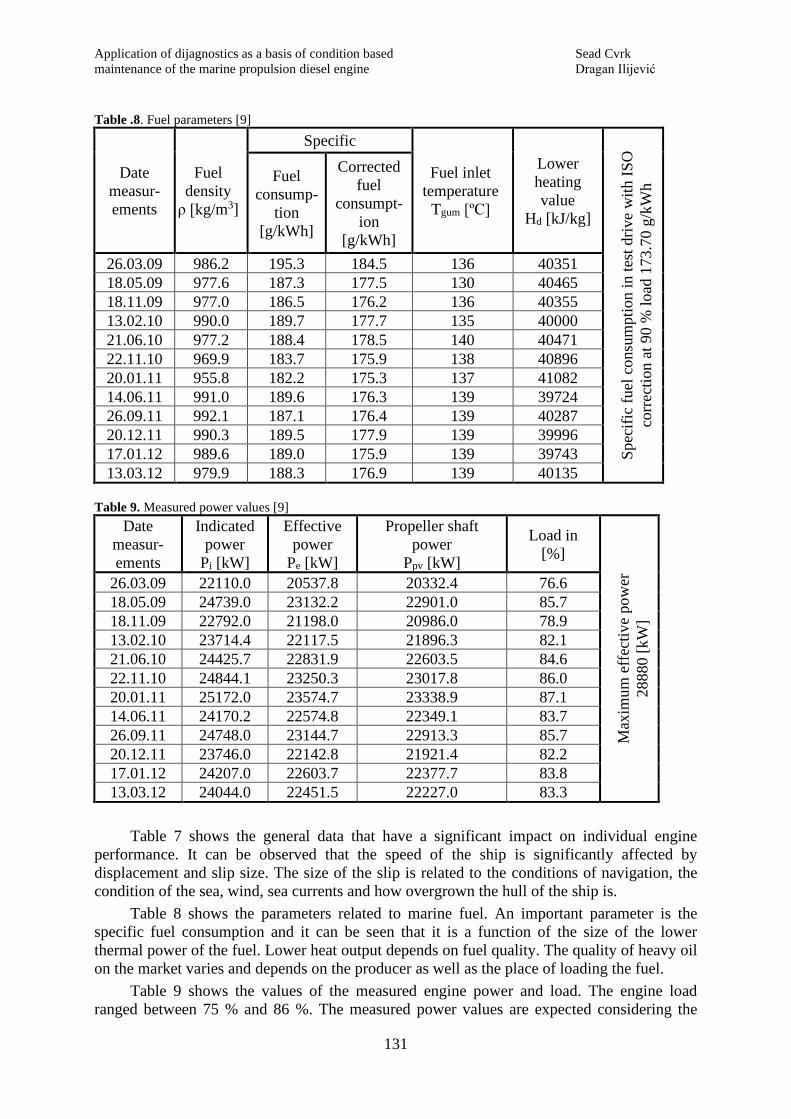
131
Table .8. Fuel parameters [9]
Date
measur-
ements
Fuel
density
ρ [kg/m3]
Specific
Fuel inlet
temperature
Tgum [ºC]
Lower
heating
value
Hd [kJ/kg]
Spec
ific
fuel
consu
mpti
on i
n t
est
dri
ve
wit
h I
SO
corr
ecti
on a
t 90
% l
oad
173.7
0 g
/kW
h Fuel
consump-
tion
[g/kWh]
Corrected
fuel
consumpt-
ion
[g/kWh]
26.03.09 986.2 195.3 184.5 136 40351
18.05.09 977.6 187.3 177.5 130 40465
18.11.09 977.0 186.5 176.2 136 40355
13.02.10 990.0 189.7 177.7 135 40000
21.06.10 977.2 188.4 178.5 140 40471
22.11.10 969.9 183.7 175.9 138 40896
20.01.11 955.8 182.2 175.3 137 41082
14.06.11 991.0 189.6 176.3 139 39724
26.09.11 992.1 187.1 176.4 139 40287
20.12.11 990.3 189.5 177.9 139 39996
17.01.12 989.6 189.0 175.9 139 39743
13.03.12 979.9 188.3 176.9 139 40135
Table 9. Measured power values [9]
Date
measur-
ements
Indicated
power
Pi [kW]
Effective
power
Pe [kW]
Propeller shaft
power
Ppv [kW]
Load in
[%]
Max
imum
eff
ecti
ve
po
wer
28880 [
kW
]
26.03.09 22110.0 20537.8 20332.4 76.6
18.05.09 24739.0 23132.2 22901.0 85.7
18.11.09 22792.0 21198.0 20986.0 78.9
13.02.10 23714.4 22117.5 21896.3 82.1
21.06.10 24425.7 22831.9 22603.5 84.6
22.11.10 24844.1 23250.3 23017.8 86.0
20.01.11 25172.0 23574.7 23338.9 87.1
14.06.11 24170.2 22574.8 22349.1 83.7
26.09.11 24748.0 23144.7 22913.3 85.7
20.12.11 23746.0 22142.8 21921.4 82.2
17.01.12 24207.0 22603.7 22377.7 83.8
13.03.12 24044.0 22451.5 22227.0 83.3
Table 7 shows the general data that have a significant impact on individual engine
performance. It can be observed that the speed of the ship is significantly affected by
displacement and slip size. The size of the slip is related to the conditions of navigation, the
condition of the sea, wind, sea currents and how overgrown the hull of the ship is.
Table 8 shows the parameters related to marine fuel. An important parameter is the
specific fuel consumption and it can be seen that it is a function of the size of the lower
thermal power of the fuel. Lower heat output depends on fuel quality. The quality of heavy oil
on the market varies and depends on the producer as well as the place of loading the fuel.
Table 9 shows the values of the measured engine power and load. The engine load
ranged between 75 % and 86 %. The measured power values are expected considering the

Sead Cvrk Application of dijagnostics as a basis of maintenance
Dragan Ilijević according to the condition of the main marine diesel engine
132
sailing conditions and the displacement of the ship. Figure 5 shows a diagram of the engine
load.
12 3
4
56
7
8
6560 70 75 80 85 90 95 100 10540
50
60
70
80
90
100
110
60 %
70 %
80 %
90 %100 %
110 %
*
*
********
Load concentration
Crankshaft rotational speed [1/min]
En
gin
e lo
ad i
n [
%]
Figure 5. Engine load diagram [7]
The load diagram presents:
- upper limit of propeller characteristic when the hull and propeller of the ship are
overgrown, line 1,
- upper limit of propeller characteristic when the hull and propeller of the ship are
clean, line 2,
- limit regulatory characteristic, line 3,
- external characteristic of the engine (maximum engine power), line 4,
- maximum mean effective pressure limit, line 5,
- maximum load limit at maximum engine rotational speed, line 6,
- upper engine overload limit, line 7 and
- constant values of mean effective pressure.
Conclusion is that the load was below the upper limit of the propeller characteristic
when the hull and propeller of the ship were clean (line 2).
5. Conclusion
Maintenance of the ship's propulsion system nowadays is unthinkable without the use of
modern diagnostic procedures and diagnostic equipment. Modern technical systems such as
marine propulsion require sophisticated equipment to maintain it. For these reasons, during
the design and development of new propulsion systems, designers and constructors are
required to take care of the development of diagnostic equipment that is installed or separately
supplied with the ship's propulsion system. In this way, the suitability for servicing and
maintenance of the ship's propulsion system is ensured, ie its overall quality is enhanced and
the satisfaction of the owner and the ship's crew in charge of its maintenance is increased.
A merchant ship, in this case a container ship, is a complex system with a large number
of interconnected subsystems and as such requires intensive maintenance in order to maintain
Application of dijagnostics as a basis of condition based Sead Cvrk
maintenance of the marine propulsion diesel engine Dragan Ilijević
133
operational performance over the given period of time. The aim is to keep the proper
operating periods of the system as long as possible and the periods of failure as short as
possible, and in addition to predict and avoid system failures or to minimize the harmful
consequences of failures. This is achieved by regular and proper maintenance of the system.
The development and application of technical diagnostic methods (as part of Condition
Based Maintenance) represents a significant contribution to the rationalization of the
maintenance process of engine cylinder units. Rapid development of measuring and
calculation equipment has enabled quality control of the condition of cylinder units in the
process of exploitation and thus a wider application of Condition Based Maintenance. Proper
monitoring and diagnostics achieves better engine performance, which directly affects the
consumption of fuel and oil for lubricating the cylinder liners, system oil for engine
lubrication as well as lower emissions of harmful gases into the atmosphere. Proper operation
of the engine and satisfactory condition of the cylinder units enable an increase in the number
of working hours before needed overhaul, which brings significant savings whilst exploiting
the ship.
The cylinder unit itself is a complex system and is closely related to other marine
propulsion engine systems, such as the fuel system, the lubricating oil system and the coolant
system. The maintenance of such a complex system cannot rely on only one type of
maintenance. Conditional Based Maintenance is an important segment of the planned
maintenance system based on operating hours and time interval of individual components of
the cylinder unit system.
The results obtained by researching the main propulsion two-stroke engine "MAN B&W
8K80 MC-C" on the ship "HS SCOTT" show that the engine was properly operating and
properly maintained during the period of exploiting, and that it did not work in areas of
thermal overload. The condition of the cylinder liners until the moment of the overhaul of the
first cylinder unit was very good. The overhaul time could have been extended for a certain
period of time with regular control. The only reason for starting the overhaul of the cylinder
units was the request of the technical inspector of the company that the overhaul of all
cylinder units be completed before the expiration of the five-year ship insurance, in order to
obtain an extension of insurance for another two years. For good physical condition of
cylinder units, the beginning of engine operation is very important, when the cylinder liner,
piston and piston rings are completely new. The period of running-in of the engine is set by
the manufacturer. Gradual increase of load and proper lubrication of cylinder liners must be
strictly observed. From the obtained results, it can be concluded that in the case of this engine,
the period of running-in was done correctly.
Despite the constructive improvements of the engine, the use of electronic diagnostic
equipment and modern measuring instruments, the most important role in the application of
the method Condition Based Maintenance is played by the crew of the machine department.
Professional training and education combined with experience are the key to the success of
ship maintenance systems. In addition to education and experience, consistency and
continuity in the implementation of Condition Based Maintenance is also essential. If the
monitoring of parameters, performance recording and visual control of cylinder units are not
performed regularly and observations are not recorded, continuity in monitoring the condition
will be lost and any changes will not be noticed in a timely manner. In that case, even the
most sophisticated equipment cannot help. In everyday activities, the habit of the members of
the machine department to listen and visually control all engine systems is very important,
because the first changes are usually manifested in changes in sound, vibration, temperature
or pressure. It is very important that every observed change in these indicators is reported to
the machine operator, as timely action can prevent large-scale accidents.

Sead Cvrk Application of dijagnostics as a basis of maintenance
Dragan Ilijević according to the condition of the main marine diesel engine
134
REFERENCES
[1] D. Petković, M. Aleksić, P. Stanojević: Koncepcije održavanja, Mašinski fakultet u Zenici, Zenica, 2020.
[2] I.Šegulja, A. Bukša: Održavanje brodskog pogona, Pomorstvo, god. 20, br. 2 (2006), str. 105-118.
[3] Service Experience MAN B&W Two-stroke Diesel Engines, Copenhagen 2016.
[4] PMI System Pressure analyser, MAN B&W Diesel, Copenhagen 2005.
[5] CoCoS Maintenance, Designed for Maintenance Excellence. MAN B&W Diesel A/S, Copenhagen 2005.
[6] LDM Liner Diameter Measuring Instrument, Chris-Marine AB, Sweden 2019. https://www.chris-
marine.com/wp-content/uploads/2019/02/LDM-B150-1801E_LR.pdf
[7] Instruction Manual Dosan-MAN B&W Diesel Engines 8K80 MC-C, Copenhagen 2007.
[8] M.Tomić, S.Petrović: Motori sa unutrašnjim sagorevanjem, Mašinski Fakultet, Beograd, 1994.
[9] Ship archive HS SCOTT
Submitted: 08.08.2020.
Accepted: 21.09.2020.
mr sci Sead Cvrk, [email protected]
University of Montenegro, Maritime faculty
Put I Bokeljske brigade 44, Kotor, Montenegro
mr Dragan Ilijević, [email protected]
Swire Pacific Offshore (Pte) Ltd
300 Beach Rd, #15-01 The Concourse, Singapur