APPLICATION OF COMPUTATIONAL FLUID … OF COMPUTATIONAL FLUID DYNAMICS TO UNDERSTAND ... and...
10
APPLICATION OF COMPUTATIONAL FLUID DYNAMICS TO UNDERSTAND QUENCHING PROBLEMS To be presented at the 18th Congress IFHTSE International Federation for Heat Treatment and Surface Engineering 18th Congress July 26th - 30th, 2010 – Rio de Janeiro, Brazil D. S. MacKenzie, PhD, FASM Houghton International, Inc. Valley Forge, PA USA 19426 Abstract The use of CFD (Computational Fluid Dynamics) is a powerful tool to reduce distortion, improve yield and to improve "first-time" quality. In this paper, examples of how CFD can improve agitation in "real-world" applications are provided. Introduction Heat treating and quenching is a complex business. The configuration of parts is endless, as is the types of furnaces available for heat-treating (Figure 1). Numerous variables in the quenching process alone govern the ability of a part to meet distortion requirements (Figure 2). Heat-treating is a constant balancing process. It is important to balance the ability of the material to achieve properties, while at the same time control distortion. Because of the complexity of the heat-treating process, it is difficult to understand the interaction of fluid flow and parts on part distortion and properties. Often understanding is achieved only by experience, which comes from making mistakes and learning from those mistakes. However, the workforce is aging, and there is less tolerance for “trial and error”. The emphasis is on “doing it right the first time”. Unfortunately there are few design rules that dictate the racking of a part in a given furnace. One method that allows the investigation of quenchant flow in a quench tank is Computational Fluid Dynamics (CFD). CFD is a mathematical technique that models continuous fluids with partial differential equations (PDE). These PDEs are discretized into smaller algebraic equations, which can then be solved using advanced mathematical techniques. The primary benefit of CFD is the ability to simulate physical behavior that is difficult to measure. This can include such things as physical phenomena (weather, stellar evolution), physical hazards (pollution and explosions); or large-scale simulations such as the aerodynamic behavior of aircraft or ships. This method of analysis lets the designer to simulate performance before building the part. This avoids the costly “build and test” methodology previously used in industry. This technique offers high accuracy, rapid results and is cost- effective. Figure 1 – Typical loads found in a heat treating shop. The interaction of the quenchant and parts is difficult to understand and predict.
Transcript of APPLICATION OF COMPUTATIONAL FLUID … OF COMPUTATIONAL FLUID DYNAMICS TO UNDERSTAND ... and...

APPLICATION OF COMPUTATIONAL FLUID DYNAMICS TO UNDERSTAND QUENCHING PROBLEMS
To be presented at the 18th Congress IFHTSE
International Federation for Heat Treatment and Surface Engineering 18th Congress
July 26th - 30th, 2010 – Rio de Janeiro, Brazil
D. S. MacKenzie, PhD, FASM Houghton International, Inc. Valley Forge, PA USA 19426 Abstract
The use of CFD (Computational Fluid Dynamics) is a powerful tool to reduce distortion, improve yield and to improve "first-time" quality. In this paper, examples of how CFD can improve agitation in "real-world" applications are provided.
Introduction
Heat treating and quenching is a complex business. The configuration of parts is endless, as is the types of furnaces available for heat-treating (Figure 1). Numerous variables in the quenching process alone govern the ability of a part to meet distortion requirements (Figure 2). Heat-treating is a constant balancing process. It is important to balance the ability of the material to achieve properties, while at the same time control distortion. Because of the complexity of the heat-treating process, it is difficult to understand the interaction of fluid flow and parts on part distortion and properties. Often understanding is achieved only by experience, which comes from making mistakes and learning from those mistakes. However, the workforce is aging, and there is less tolerance for “trial and error”. The emphasis is on “doing it right the first time”. Unfortunately there are few design rules that dictate the racking of a part in a given furnace.
One method that allows the investigation of quenchant flow in a quench tank is Computational Fluid Dynamics (CFD). CFD is a mathematical technique that models continuous fluids with partial differential equations (PDE). These PDEs are discretized into smaller algebraic equations, which can then be solved using advanced mathematical techniques.
The primary benefit of CFD is the ability to simulate physical behavior that is difficult to measure. This can include such things as physical phenomena (weather, stellar evolution), physical hazards (pollution and explosions); or large-scale simulations such as the aerodynamic behavior of aircraft or ships. This method of analysis lets the designer to simulate performance before building the part. This avoids the costly “build and test” methodology previously used in industry. This technique offers high accuracy, rapid results and is cost- effective.
Figure 1 – Typical loads found in a heat treating shop. The interaction of the quenchant and parts is difficult to understand and predict.
Typical CFD Process
There are several basic steps in solving a problem by CFD. These are: • Formulate basic assumptions; • Define the physical and computational problem; • Determine solution strategy; and • Analysis of results.
Many of these steps are accomplished internal to the software, and does not require any operator intervention. However, it is important to know what is involved to improve the basic decision-making, and how to set up problems.
During the formulation of the basic assumptions, it is useful to know whether the flow is incompressible or compressible. This dictates the type of solution and solver. For most immersion quenching applications, the quenchant is incompressible. It is also important to know the estimated Reynolds number of the flow. This dictates whether the flow is laminar or turbulent and impacts the type of solution obtainable. Typically, turbulent flow is difficult to model, however time averaged results can be obtained. Laminar flow is much easier to model.
Next the physical problem must be defined. This requires establishing the physical constraints of the system and defining the boundary conditions. Often the physical model can be simply importing a CAD file. Often however, the CAD file must be cleaned up for subsequent solution by the CFD solver.
For most CFD problems, the largest bottleneck is the importation and translation of CAD models into a suitable model for CFD. This requires the elimination of components not exposed to the fluid flow, and making the component “water-tight”. Small details are eliminated, as well as duplicate entities. Finally, the geometrical connections to the model must be rebuilt.
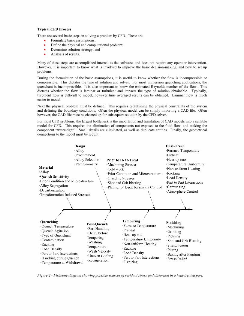
Figure 2 - Fishbone diagram showing possible sources of residual stress and distortion in a heat-treated part.

In general, realistic geometries are too complicated to be generated from simple shapes, unless the elements are extremely small. However, as the mesh element size is reduced, the computation time is geometrically increased, as well as the complexity of the problem.
The mesh must be established on the model, and the boundary conditions applied. Often meshing of the model is difficult, and requires an understanding of the desired results. A decision must be made regarding the mesh elements (brick, tetrahedron, block, etc). Because of the number of different meshing elements available, there are many ways to accomplish meshing – each with different attributes.
The solution strategy is really an understanding of the physical problem, and how to approach getting the desired results. For instance, if it is desired to know the fluid flow around a set of parts during quench tank design, then a static analysis is appropriate. If it is desired to know the generation of stresses in a part, as a function of a heat treated workload, then a time-dependant analysis would be appropriate. The primary difference is the complexity of the solution. As the analysis takes into account more factors (time, temperature, etc.) the solution of the problem becomes significantly more difficult and complicated. It also substantially increases the amount of computational time, and the amount of data that must be reduced.
Once the mesh is established, the CFD solver does the calculations and produces the results. The flow characteristics of the mesh are determined by solving the Navier-Stokes equations at each node or corner of the mesh. These equations describe how velocity, pressure, temperature and viscosity of a moving fluid are related. G.G. Stokes, in England, and M. Navier, in France, derived these equations independently in the early 1800's. The equations are a set of coupled differential equations and could, in theory, be solved for a given flow problem by using methods from calculus. But, in practice, these equations are too difficult to solve analytically.
CFD is very computationally intense. Previously it required the use of specialized CRAY super computers or networked RISC workstations. However, because of the increase in computing capability and improved algorithms, fairly complex CFD models can now be performed on everyday office computers or laptops.
Analysis of the data is the final step in CFD examination, and involves organization and interpretation of the data and images. In addition, the convergence of the solution is examined. An example of the results of a CFD analysis is shown in Figure 3. A variety of programs are available to help understand and represent the data.
Figure 3 - Post-processed CFD data showing the velocity contours as a function of crank angle in a four-stoke internal combustion engine (Courtesy Fluent, Inc.)
Case Histories
To illustrate the power of Computational Fluid Dynamics, a series of case histories was developed. The configurations of the quench tanks examined are typical of both open quench tanks, and those quench tanks found in typical integral quench furnaces.

Case History I. A small quench tank was used to determine concentration of polyalkylene-glycol quenchants for quenching aluminum. Parts consisting of small hand forgings were used. Large variations in the concentration were observed to obtain necessary properties. The quench tank was approximately 1m x 1m x 1m, with a four-bladed marine impeller with 1:1 pitch as the agitation source located in one corner of the tank. The agitator was slightly inclined. No baffles were present. Because of the large concentration variations observed, it was determined to examine the source of variation. After much discussion, it was thought to be associated with variations in agitation. A study using CFD was conducted to examine the velocity profiles within the quench tank. The quench tank and the resulting mesh are shown in Figure 4.
The tank was meshed into approximately 180,000 nodes, and the agitator modeled as a disk. Using a series of networked parallel RISC processors, the flow field in the quench tank was determined. The results are shown in Figure 5.
The results of the CFD analysis showed that the tank was “dead” with very little agitation. What agitation was present was located along the sides of the tank. If a part was hand quenched near the sides opposite the agitator, much higher agitation would be present, resulting in higher properties. If parts were quenched in the center of the quench tank, virtually no agitation was present, and lower properties would be observed.
This analysis, conducted in 1991, is probably the first CFD analysis of a quench tank, and showed the power of CFD.
Figure 4 – Quench tank used for determining proper concentration of polyalkylene-glycol quenchants for quenching aluminum for AMS-2770.
Figure 5 – Resultant flow fields of CFD model of Case I.
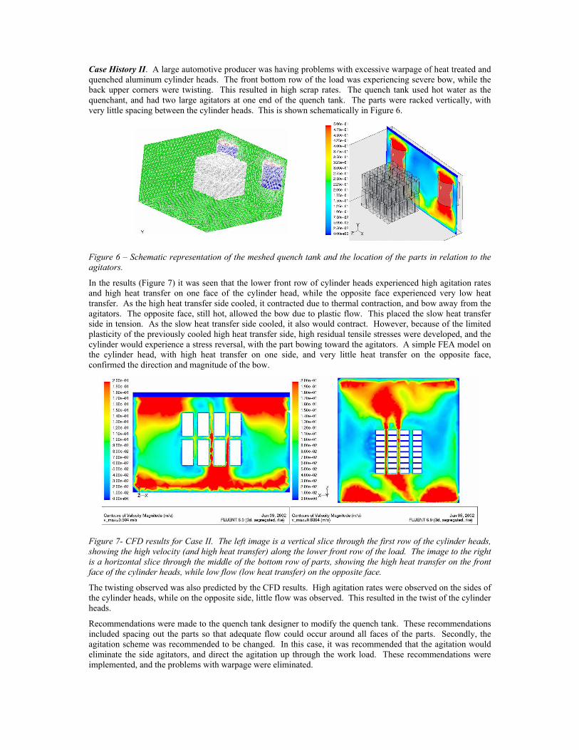
Case History II. A large automotive producer was having problems with excessive warpage of heat treated and quenched aluminum cylinder heads. The front bottom row of the load was experiencing severe bow, while the back upper corners were twisting. This resulted in high scrap rates. The quench tank used hot water as the quenchant, and had two large agitators at one end of the quench tank. The parts were racked vertically, with very little spacing between the cylinder heads. This is shown schematically in Figure 6.
Figure 6 – Schematic representation of the meshed quench tank and the location of the parts in relation to the agitators.
In the results (Figure 7) it was seen that the lower front row of cylinder heads experienced high agitation rates and high heat transfer on one face of the cylinder head, while the opposite face experienced very low heat transfer. As the high heat transfer side cooled, it contracted due to thermal contraction, and bow away from the agitators. The opposite face, still hot, allowed the bow due to plastic flow. This placed the slow heat transfer side in tension. As the slow heat transfer side cooled, it also would contract. However, because of the limited plasticity of the previously cooled high heat transfer side, high residual tensile stresses were developed, and the cylinder would experience a stress reversal, with the part bowing toward the agitators. A simple FEA model on the cylinder head, with high heat transfer on one side, and very little heat transfer on the opposite face, confirmed the direction and magnitude of the bow.
Figure 7- CFD results for Case II. The left image is a vertical slice through the first row of the cylinder heads, showing the high velocity (and high heat transfer) along the lower front row of the load. The image to the right is a horizontal slice through the middle of the bottom row of parts, showing the high heat transfer on the front face of the cylinder heads, while low flow (low heat transfer) on the opposite face.
The twisting observed was also predicted by the CFD results. High agitation rates were observed on the sides of the cylinder heads, while on the opposite side, little flow was observed. This resulted in the twist of the cylinder heads.
Recommendations were made to the quench tank designer to modify the quench tank. These recommendations included spacing out the parts so that adequate flow could occur around all faces of the parts. Secondly, the agitation scheme was recommended to be changed. In this case, it was recommended that the agitation would eliminate the side agitators, and direct the agitation up through the work load. These recommendations were implemented, and the problems with warpage were eliminated.

Case History III. A forging company was quenching large alloy steel slabs, and observing non-uniform hardness and bowing of the plate. We were asked to examine the quench tank and make recommendations to modify the quench tank so that better uniformity of quenching would result.
The quench tank was large, approximately 12 meters long, 4 meters wide and 4 meters deep. It is shown in Figure 8. Ten agitators were located on one side of the tank, with two adjustable baffles to direct the flow. The agitators where located in draft tubes underneath the slab, and would direct the flow along the baffles.
CFD analysis was conducted on the initial design to determine the cause of the non-uniform hardness and warpage. It was observed that the quenchant flow across the slab was non-uniform and inefficient. Flow would stall at the exit end of the nozzle, with flow separating from the top surface of the upper baffle, causing turbulence and loss of effectiveness. A lateral short-circuiting of the flow would occur between the nozzles, reducing the exit velocity at the baffles, further reducing the flow efficiency. Flow would stall at the top and bottom of the slab, with short-circuiting of the flow between the slab and the entrance of the baffle. The flow would vertex, and the resulting turbulence would further reduce quenchant flow and further reduce flow uniformity. The minimum flow velocity on the slab surface was 0.003 m/s and the maximum velocity was 0.883 m/s. The variability in quenchant speed across the plate contributes to large residual stress fields and distortion (bowing and twisting). CFD results are shown in Figure 9.
Based on the CFD analysis it was recommended to locate the resting position of the slab approximately 15 cm higher. An additional baffle was recommended beneath the slab to decrease short-circuiting and to direct flow along the bottom of the slab. An additional baffle should be located to the left of the slab to direct flow around the back side of the slab and to increase the velocity of the quenchant. It was further recommended to merge the upper baffles into a continuous sheet, preventing lateral short-circuiting of the flow. An additional baffle or stream line between the upper and lower baffles was recommended to reduce stalling or flow separation.
Figure 8 – Quench tank used to quench large alloy steel slabs approximately 25 cm thick.
Figure 9 – Resultant flow showing non-uniformity across plate when sectioned thru the middle of the Z direction.
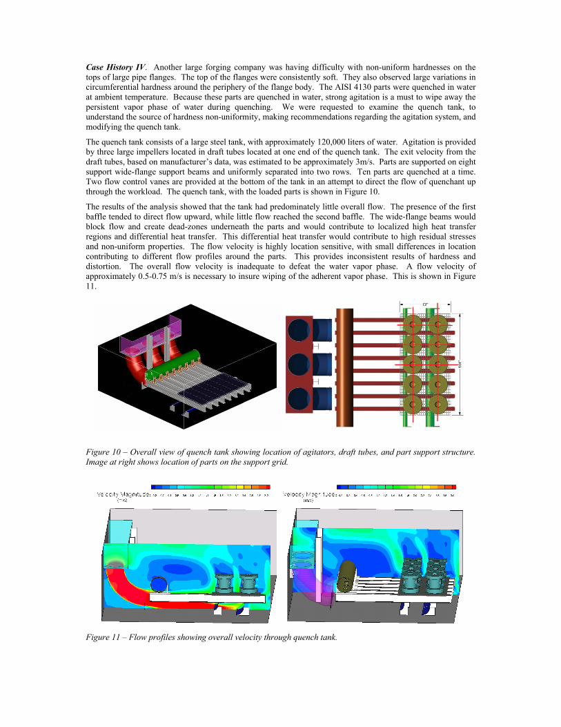
Case History IV. Another large forging company was having difficulty with non-uniform hardnesses on the tops of large pipe flanges. The top of the flanges were consistently soft. They also observed large variations in circumferential hardness around the periphery of the flange body. The AISI 4130 parts were quenched in water at ambient temperature. Because these parts are quenched in water, strong agitation is a must to wipe away the persistent vapor phase of water during quenching. We were requested to examine the quench tank, to understand the source of hardness non-uniformity, making recommendations regarding the agitation system, and modifying the quench tank.
The quench tank consists of a large steel tank, with approximately 120,000 liters of water. Agitation is provided by three large impellers located in draft tubes located at one end of the quench tank. The exit velocity from the draft tubes, based on manufacturer’s data, was estimated to be approximately 3m/s. Parts are supported on eight support wide-flange support beams and uniformly separated into two rows. Ten parts are quenched at a time. Two flow control vanes are provided at the bottom of the tank in an attempt to direct the flow of quenchant up through the workload. The quench tank, with the loaded parts is shown in Figure 10.
The results of the analysis showed that the tank had predominately little overall flow. The presence of the first baffle tended to direct flow upward, while little flow reached the second baffle. The wide-flange beams would block flow and create dead-zones underneath the parts and would contribute to localized high heat transfer regions and differential heat transfer. This differential heat transfer would contribute to high residual stresses and non-uniform properties. The flow velocity is highly location sensitive, with small differences in location contributing to different flow profiles around the parts. This provides inconsistent results of hardness and distortion. The overall flow velocity is inadequate to defeat the water vapor phase. A flow velocity of approximately 0.5-0.75 m/s is necessary to insure wiping of the adherent vapor phase. This is shown in Figure 11.
Figure 10 – Overall view of quench tank showing location of agitators, draft tubes, and part support structure. Image at right shows location of parts on the support grid.
Figure 11 – Flow profiles showing overall velocity through quench tank.

The overall flow on top of the parts is poor because of wake effects from the upper flange. This results in slow quench rates and poor hardness. The lower flange tends to reduce flow at the sides of the part because of wake effects. The front parts see much lower overall flow velocities than the back parts, contributing to non-uniform response and distortion. This is shown in Figure 12.
Several recommendations were made. Additional agitation on the back sides of the parts to increase the overall flow around the parts was suggested. It was also recommended to redirect the bottom deflectors to direct the flow upwards at an earlier time. It was suggested to remove the second deflector as it was non-functional. Additional agitation directed at the upper flanges and across the lower flanges would be required to eliminate the wake effects from the upward flow around the flanges. It was further recommended to use a small percentage of a polymer quenchant to provide for more uniform heat transfer across all surfaces of the parts to yield more uniform hardness and reduced residual stresses. An additional suggestion was to cut the flanges from the support beams. This would act as a flow “smoother”, and reduce the turbulence from the flanges on the beams. It would also increase the upward flow through the part workload.
Figure 12 – Orthogonal view with sections through parts, showing non-uniformity of quenchant flow around parts.
Case History V. An automotive supplier was having difficulty quenching large pinion gears for automatic transmissions. The pinion gears were AISI 8620 pinion gears that are carburized to obtain a case depth of approximately 0.7 mm. The parts were carburized at 925°C for six hours, and then quenched from a temperature of 815°C. These parts were quenched in to Mar-Temp 355 (a fast quench oil) at a temperature of 125°C. These parts were then washed and subsequently tempered at 175°C. It was experiencing bowing of the stem of approximately 2.5 mm, which caused excessive loading of the drive-train, and excessive noise, as well as excessive rework. Houghton International, Inc. was requested to help understand and provide cost effective solutions to eliminate the distortion.
Figure 13: Comparison of existing and proposed racking methods.
The existing method of loading was pinion head down in a pyramidal stack, and a new method of racking was proposed to minimize his distortion (Figure 13). This method was suggested to improve fluid flow around the pinions, reduce distortion and improve loading of the rack. The customer wanted to understand how the proposed method would reduce the distortion, and understand how uniform quenching would be with the proposed rack in the existing quench system.
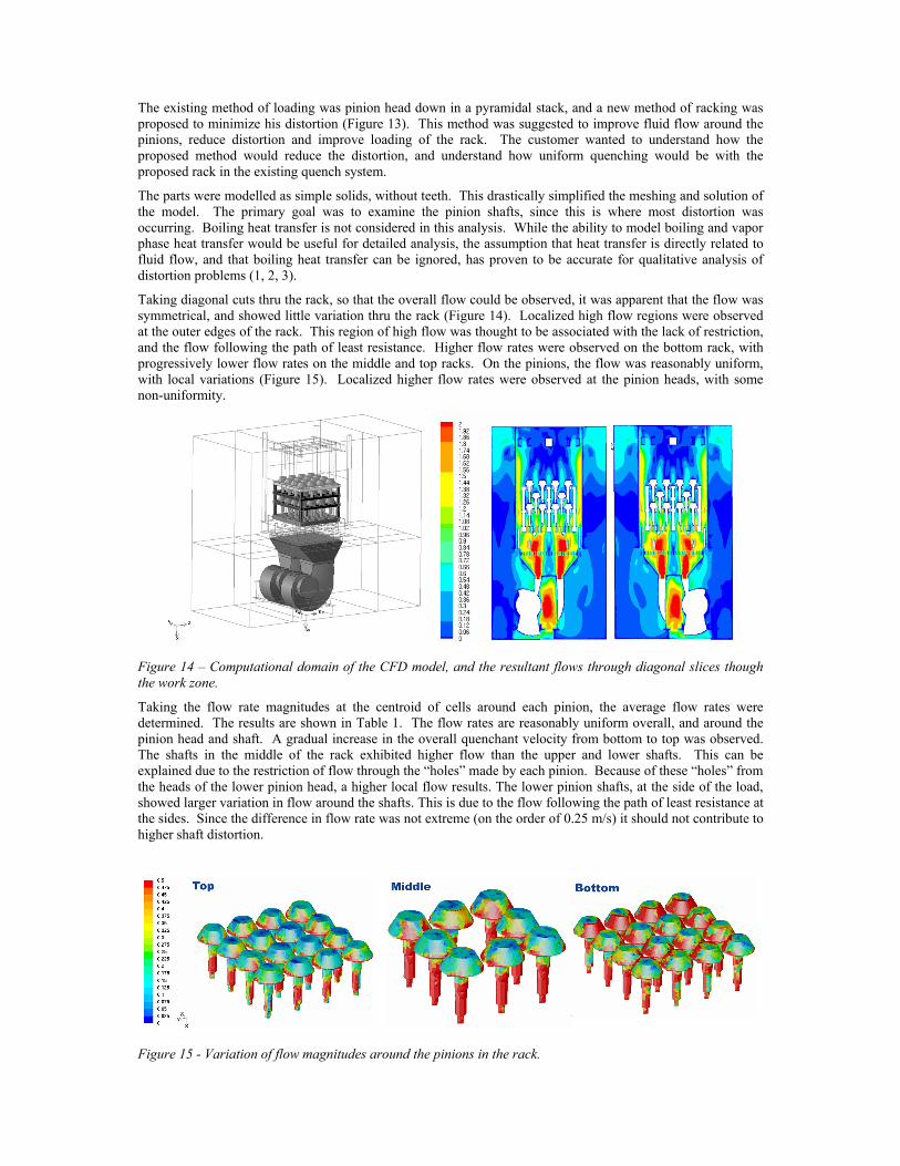
The parts were modelled as simple solids, without teeth. This drastically simplified the meshing and solution of the model. The primary goal was to examine the pinion shafts, since this is where most distortion was occurring. Boiling heat transfer is not considered in this analysis. While the ability to model boiling and vapor phase heat transfer would be useful for detailed analysis, the assumption that heat transfer is directly related to fluid flow, and that boiling heat transfer can be ignored, has proven to be accurate for qualitative analysis of distortion problems (1, 2, 3).
Taking diagonal cuts thru the rack, so that the overall flow could be observed, it was apparent that the flow was symmetrical, and showed little variation thru the rack (Figure 14). Localized high flow regions were observed at the outer edges of the rack. This region of high flow was thought to be associated with the lack of restriction, and the flow following the path of least resistance. Higher flow rates were observed on the bottom rack, with progressively lower flow rates on the middle and top racks. On the pinions, the flow was reasonably uniform, with local variations (Figure 15). Localized higher flow rates were observed at the pinion heads, with some non-uniformity.
Figure 14 – Computational domain of the CFD model, and the resultant flows through diagonal slices though the work zone.
Taking the flow rate magnitudes at the centroid of cells around each pinion, the average flow rates were determined. The results are shown in Table 1. The flow rates are reasonably uniform overall, and around the pinion head and shaft. A gradual increase in the overall quenchant velocity from bottom to top was observed. The shafts in the middle of the rack exhibited higher flow than the upper and lower shafts. This can be explained due to the restriction of flow through the “holes” made by each pinion. Because of these “holes” from the heads of the lower pinion head, a higher local flow results. The lower pinion shafts, at the side of the load, showed larger variation in flow around the shafts. This is due to the flow following the path of least resistance at the sides. Since the difference in flow rate was not extreme (on the order of 0.25 m/s) it should not contribute to higher shaft distortion.
Figure 15 - Variation of flow magnitudes around the pinions in the rack.

Overall Head Shaft
Average Std. Dev. Average
Std. Dev. Average
Std. Dev.
Top 0.329 0.078 0.269 0.031 0.400 0.028 Middle 0.470 0.039 0.299 0.016 0.921 0.096 Bottom 0.526 0.045 0.586 0.032 0.519 0.047
Table 1: Average flow rates of the quenchant around the pinions in the rack.
The results showed substantially reduced flow variation around the pinion shafts. A series of racks were obtained, and 2400 parts were quenched in 60 loads. The pinions were measured for distortion and found that the maximum distortion observed was 0.020 mm – a several order of magnitude improvement. The resultant savings to the customer were in excess of $14,000,000 USD.
Summary and Conclusions
In this paper the application of Computational Fluid Dynamics to the design of quench tanks has been shown. The interaction of work-pieces, agitation, baffles and quench tank design can be understood before the quench tank is constructed. Changes in the arrangement of baffles and agitation systems can be examined during the design of the quench tank before the quench tank design is constructed. This saves considerable time and effort, and can ensure that the quench tank will perform as expected. First time quality is assured.
Acknowledgements
The authors would like to thank the management of Houghton International, Inc., Air Flow Sciences, Inc. and ANSYS, Inc. for allowing us to explore this application of Computational Fluid Dynamics, and allowing us to present this paper at the ABM/IFHTSE Conference in Rio de Janeiro.
References:
1 D.S. MacKenzie, Zhichao Li, and B. Lynn Ferguson, 2007, Effect of Quenchant Flow on the Distortion of Carburized Automotive Pinion Gears, International Federation for Heat Treatment and Surface Engineering – IFHTSE, 5th International Conference on Quenching and Control of Distortion, European Conference on Heat Treatment 2007, Berlin, April 25 – 27, 2007 2 Sankaran, K.K., Tuegel, E.J., Kremer, K.L., Schwartz, D.S., First Intl. Non-Ferrous and Technology Conf., Eds., T. Bains, D.S. MacKenzie, St. Louis, 1997, ASM Intl. Materials Park OH, 1997, 325 3 MacKenzie, D.S., Totten, G.E., Gopinath, N., Proc.10th Congress of the IFHT, Eds. T. Bell and E.J. Mittemeijer, IOM Communications Ltd., London, England, 1999, 655-669.