Application of CFD in C/R Design 胡石政 PERFORMANCE COMPARSION OF AXIAL FAN AND FAN-FILTER...
20
Application of CFD Application of CFD in C/R Design in C/R Design < < 主主主 主主主 > > 胡胡胡 胡胡胡 PERFORMANCE COMPARSION OF PERFORMANCE COMPARSION OF AXIAL FAN AND FAN-FILTER AXIAL FAN AND FAN-FILTER UNIT(FFU) UNIT(FFU) TYPE CLEAN ROOMS BY CFD TYPE CLEAN ROOMS BY CFD
-
date post
20-Dec-2015 -
Category
Documents
-
view
223 -
download
2
Transcript of Application of CFD in C/R Design 胡石政 PERFORMANCE COMPARSION OF AXIAL FAN AND FAN-FILTER...

Application of CFD Application of CFD in C/R Designin C/R Design
<< 主講人主講人 >>胡石政胡石政
PERFORMANCE COMPARSION OFPERFORMANCE COMPARSION OFAXIAL FAN AND FAN-FILTER AXIAL FAN AND FAN-FILTER
UNIT(FFU)UNIT(FFU)TYPE CLEAN ROOMS BY CFDTYPE CLEAN ROOMS BY CFD

OutlineOutline INTRODUCTIONINTRODUCTION NUMERICAL METHODSNUMERICAL METHODS
Airflow model Airflow model Boundary conditionsBoundary conditions
RESULTS AND DISCUSSIONRESULTS AND DISCUSSION CONCLUSIONSCONCLUSIONS

INTRODUCTIONINTRODUCTION
Recirculation systems currently account foRecirculation systems currently account for about fifteen percent of the electrical conr about fifteen percent of the electrical consumption of a fab.sumption of a fab.
There are several types of air recirculation There are several types of air recirculation systems available for uni-directional clean systems available for uni-directional clean rooms in practice includingrooms in practice including ::a. the axial fan type systema. the axial fan type systemb. the fan-filter unit (FFU) type systemb. the fan-filter unit (FFU) type systemc. the recirculation air-conditioner type systemc. the recirculation air-conditioner type system

axial fan type systemaxial fan type system

fan-filter unit (FFU) type systemfan-filter unit (FFU) type system
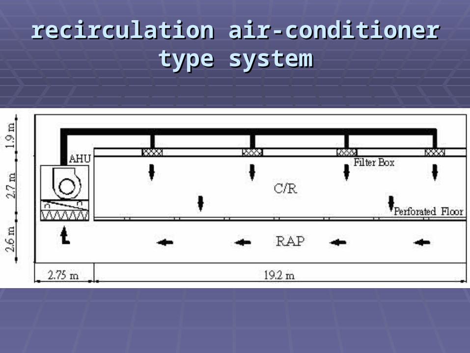
recirculation air-conditioner type systemrecirculation air-conditioner type system

Schematic diagram of the FFUSchematic diagram of the FFU
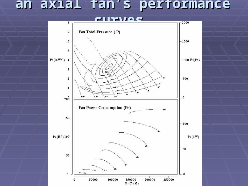
an axial fan’s performance curvesan axial fan’s performance curves
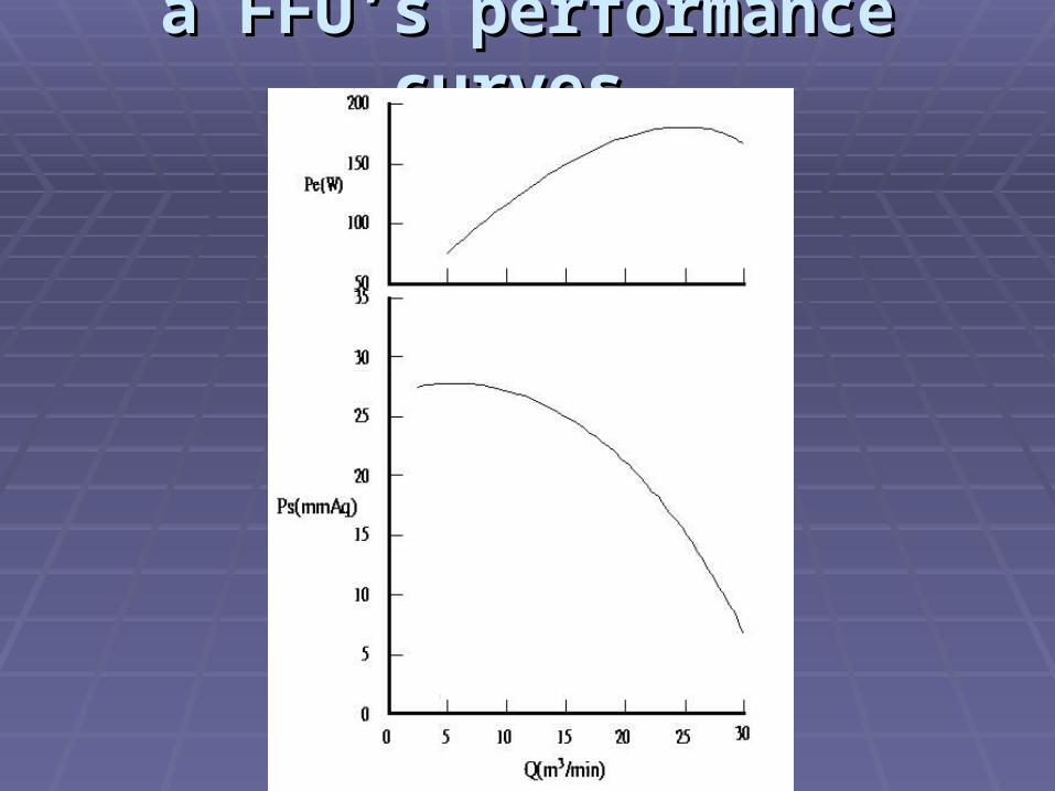
a FFU’s performance curvesa FFU’s performance curves

non-uniformity of ULPA filter face vnon-uniformity of ULPA filter face velocity (NU) elocity (NU)
face
2/1
2n
1
facei
V
)1n(
)VV(
NU
ratio of standard deviation of the velocity to the mean face velocity
Airflow modelAirflow model
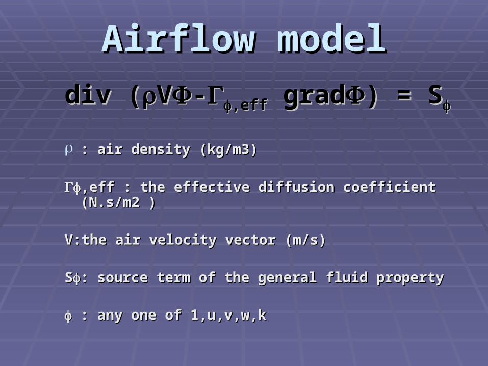
div (div (VV--,eff,eff grad grad) = S) = S
: air density (kg/m3): air density (kg/m3)
,eff : the effective diffusion coefficient (N.s/m2 ),eff : the effective diffusion coefficient (N.s/m2 )
V:the air velocity vector (m/s)V:the air velocity vector (m/s)
SS: source term of the general fluid property: source term of the general fluid property
: any one of 1,u,v,w,k: any one of 1,u,v,w,k

The Case Setup The Case Setup CASE C/R Type L(m) Hs(m) Hr(m) Pf Pp Ps Psys. eff Pc
1 Axial Fan 24 1.9 2.6 300Vf 80Vp2 25Vs 25Vout
2 30Vc2
2 Axial Fan 19.2 1.9 2.6 300Vf 80Vp2 25Vs 25Vout
2 30Vc2
3 Axial Fan 14.4 1.9 2.6 300Vf 80Vp2 25Vs 25Vout
2 30Vc2
4 Axial Fan 9.6 1.9 2.6 300Vf 80Vp2 25Vs 25Vout
2 30Vc2
5 FFU 24 1.9 2.6 300Vf 80Vp2 N N 4Vc
2
6 FFU 19.2 1.9 2.6 300 Vf 80Vp2 N N 6Vc
2
7 FFU 14.4 1.9 2.6 300Vf 80Vp2 N N 10Vc
2
8 FFU 9.6 1.9 2.6 300Vf 80Vp2 N N 20Vc
2
SubscriptSubscript :: rr-return air chamber-return air chamber ss-supply air chamber-supply air chamber
cc-Dry coil-Dry coil pp-Perforated floor-Perforated floor ff-ULPA filter-ULPA filterss-Silencer & System effect of the axial fan -Silencer & System effect of the axial fan
deflection angle (α)deflection angle (α)
Airflow deflection angle, α, in the working zoAirflow deflection angle, α, in the working zone is affected by ne is affected by ULPA face velocity non-uniformityULPA face velocity non-uniformity flow resistance across the perforated floors flow resistance across the perforated floors clean room heightclean room height
To adjust the α value by increasing the airfloTo adjust the α value by increasing the airflow resistance of the perforated floor may crew resistance of the perforated floor may create too much resistance to the FFU resultinate too much resistance to the FFU resulting insufficient system flow rate g insufficient system flow rate

Comparison of system performance for axial fan Comparison of system performance for axial fan
type clean room and FFU type clean roomtype clean room and FFU type clean room CASE
C/RType
L(m) Qt(m3/h) Ps(Pa) Pe(W)
Pe/Qt
(W/CMM) NU(%)
1AxialFan
24 241,500 980 83,000 20.62 22 38
2AxialFan
19.2 173,300 720 44,000 15.23 19 23
3AxialFan
14.4 112,800 454 23,000 12.23 8.3 6.2
4AxialFan
9.6 81,350 282 11,500 8.48 1 0.9
Average 152,237 609 40,375 14.14 12.57 17
5 FFU 24 221,440 170 27,520 7.45 20.4 2.37
6 FFU 19.2 181,248 164 22,400 7.41 10.9 1.55
7 FFU 14.4 138,720 158 17,088 7.39 4 0.97
8 FFU 9.6 94,208 152 11,520 7.16 0.1 0.47
Average 158,904 161 19,632 7.35 8.85 1.34
predicted power consumption per unit air quantity

Comparison of total annual charge for axial Comparison of total annual charge for axial fan type clean room and FFU type clean fan type clean room and FFU type clean
roomroom
CASE
Running Cost Heat Load CostTotal
Charge(NT$/year)
Total Power Consumption
(kWh/year)
CurrencyCharge
(NT$/year)
Total Heat Load
(kWh/year)
CurrencyCharge
(NT$/year)
1 727,080 1454,160 144,754 289,508 1743,668
2 385,440 770,880 76,737 153,474 924,354
3 201,480 402,960 40,112 80,224 483,184
4 100,740 201,480 20,056 40,112 241,592
Average 353,685 707,370 70,414 140,828 848,198
5 241,075 482,150 47,995 95,900 578,050
6 196,224 392,448 39,066 78,132 470,580
7 149,620 299,240 29,802 59,604 358,844
8 100,915 201,830 20,091 40,182 242,012
Average 171,958 343,916 34,238 68,454 412,370

Comparison of the predicted and experimental dataComparison of the predicted and experimental data

Velocity Vectors (m/s) Velocity Vectors (m/s)
Axial Fan system FFU system
the FFU type system splits the system total fthe FFU type system splits the system total flow volume to individual FFUs, the highest filow volume to individual FFUs, the highest field velocity value of FFU system is lower thaeld velocity value of FFU system is lower than that of axial fan system. n that of axial fan system.
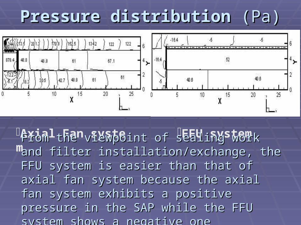
Pressure distribution Pressure distribution (Pa)(Pa)
FFU system Axial Fan system
From the viewpoint of sealing work and filter From the viewpoint of sealing work and filter installation/exchange, the FFU system is easier installation/exchange, the FFU system is easier than that of axial fan system because the axial fan than that of axial fan system because the axial fan system exhibits a positive pressure in the SAP system exhibits a positive pressure in the SAP while the FFU system shows a negative onewhile the FFU system shows a negative one
CONCLUSIONSCONCLUSIONS For the first time, the fan performance curve was For the first time, the fan performance curve was
successfully input to the CFD model to investigate the successfully input to the CFD model to investigate the operational characteristics of both the axial type clean operational characteristics of both the axial type clean room and the fan-filter unit (FFU) type clean room. The room and the fan-filter unit (FFU) type clean room. The feasibility of such connection was verified and the feasibility of such connection was verified and the predicted results were promising. predicted results were promising.
The performance of the FFU system examined is superior The performance of the FFU system examined is superior to that of the axial fan system based on the non-uniformity to that of the axial fan system based on the non-uniformity of the ULPA filter face velocity, deflection angle of airflow of the ULPA filter face velocity, deflection angle of airflow in the working zone, and energy consumption. However, in the working zone, and energy consumption. However, more studies are required to understand the performance more studies are required to understand the performance of these two systems to include the initial cost, the of these two systems to include the initial cost, the maintenance cost, the flexibility of space management etc.maintenance cost, the flexibility of space management etc.

E N DE N D


![Tall & Flat Structures [a Comparsion]](https://static.fdocuments.in/doc/165x107/546a6a6eb4af9f8e2c8b46e9/tall-flat-structures-a-comparsion.jpg)


![FINAL PROJECT: EVAPORATOR FAN DESIGNchristopherphaneuf.com/cfd/me407_final_report[phaneuf-tovar].pdf · FINAL PROJECT: EVAPORATOR FAN DESIGN ... INTRODUCTION 1 1.1 ... Using Solidworks,](https://static.fdocuments.in/doc/165x107/5aa782ce7f8b9a294b8c30d4/final-project-evaporator-fan-desi-phaneuf-tovarpdffinal-project-evaporator-fan.jpg)