APPLICATION OF BUCK CONVERTER ON THREE PHASE INDUCTION...
11
International Journal of Innovative Research in Advanced Engineering (IJIRAE) ISSN: 2349-2163 Issue 11, Volume 4 (November 2017) www.ijirae.com _________________________________________________________________________________________________ IJIRAE: Impact Factor Value – SJIF: Innospace, Morocco (2016): 3.916 | PIF: 2.469 | Jour Info: 4.085 | ISRAJIF (2016): 3.715 | Indexcopernicus: (ICV 2015): 47.91 IJIRAE © 2014- 17, All Rights Reserved Page –32 APPLICATION OF BUCK CONVERTER ON THREE PHASE INDUCTION MOTOR DYNAMIC BRAKING USING DC INJECT METHOD Jaka Windarta * Master Program of Energy-School of Postgraduate Studies, School of Electrical Engineering, Diponegoro University, Indonesia [email protected] Tejo Sukmadi School of Electrical Engineering, Diponegoro University, Indonesia [email protected] Maulinda Setiawan School of Electrical Engineering, Diponegoro University, Indonesia [email protected] Manuscript History Number: IJIRAE/RS/Vol.04/Issue11/NVAE10089 DOI: 10.26562/IJIRAE.2017.NVAE10089 Received: 22, October 2017 Final Correction: 30, October 2017 Final Accepted: 05, November 2017 Published: November 2017 Editor: Dr.A.Arul L.S, Chief Editor, IJIRAE, AM Publications, India Citation: Windarta, J., Sukmadi, T. & Setiawan, M. (2017). APPLICATION OF BUCK CONVERTER ON THREE PHASE INDUCTION MOTOR DYNAMIC BRAKING USING DC INJECT METHOD. IJIRAE:: International Journal of Innovative Research in Advanced Engineering, Volume IV, 32-42. doi: 10.26562/IJIRAE.2017.NVAE10089 Copyright: ©2017 This is an open access article distributed under the terms of the Creative Commons Attribution License, Which Permits unrestricted use, distribution, and reproduction in any medium, provided the original author and source are credited. Abstract— Three phase induction motors in various industries are very important to be stopped within a short time. Dynamic braking of three phase induction motor has been commonly used to break an induction motor electrically. However, dynamic braking method does not stop the rotation of the motor as quick as mechanical braking. In this research, will discuss about dynamic braking using direct current method. Buck Converter design is made as DC source for direct current braking in three phase induction motors. Based on the result of measurement, buck converter can operate on minimum duty cycle 10% with output voltage 11,3V and output current 0,16A. When duty cycle operates at maximum duty cycle 90%, output voltage is 29,95V and output current is 1,15A. The test results also prove that the buck converter was successfully applied to direct current braking of the three phase induction motor and has succeeded in stopping the motor fastest in 0.18 seconds when the motor are not coupled with DC generator and 1.7 seconds for the condition is coupled with the DC generator. Keywords— 3-ph induction motor, buck converter, direct current braking I. INTRODUCTION Three-phase induction motors are commonly used in various industries because of their simple construction, easy use, high durability, high reliability, and low maintenance costs. One of the important control parameter of induction motor is braking. Braking is needed when a system requires in stop process, either when the device operation is completed or when there is a system error to secure the equipment at work. One method of three phase induction motor braking is dynamic breaking method by injecting direct current on the stator coil of three phase induction motors after the stator coil is removed from the supply.
Transcript of APPLICATION OF BUCK CONVERTER ON THREE PHASE INDUCTION...

International Journal of Innovative Research in Advanced Engineering (IJIRAE) ISSN: 2349-2163 Issue 11, Volume 4 (November 2017) www.ijirae.com
_________________________________________________________________________________________________ IJIRAE: Impact Factor Value – SJIF: Innospace, Morocco (2016): 3.916 | PIF: 2.469 | Jour Info: 4.085 |
ISRAJIF (2016): 3.715 | Indexcopernicus: (ICV 2015): 47.91 IJIRAE © 2014- 17, All Rights Reserved Page –32
APPLICATION OF BUCK CONVERTER ON THREE PHASE
INDUCTION MOTOR DYNAMIC BRAKING USING DC INJECT METHOD
Jaka Windarta* Master Program of Energy-School of Postgraduate Studies,
School of Electrical Engineering, Diponegoro University, Indonesia [email protected]
Tejo Sukmadi School of Electrical Engineering, Diponegoro University, Indonesia
Maulinda Setiawan School of Electrical Engineering, Diponegoro University, Indonesia
[email protected] Manuscript History Number: IJIRAE/RS/Vol.04/Issue11/NVAE10089 DOI: 10.26562/IJIRAE.2017.NVAE10089 Received: 22, October 2017 Final Correction: 30, October 2017 Final Accepted: 05, November 2017 Published: November 2017 Editor: Dr.A.Arul L.S, Chief Editor, IJIRAE, AM Publications, India Citation: Windarta, J., Sukmadi, T. & Setiawan, M. (2017). APPLICATION OF BUCK CONVERTER ON THREE PHASE INDUCTION MOTOR DYNAMIC BRAKING USING DC INJECT METHOD. IJIRAE:: International Journal of Innovative Research in Advanced Engineering, Volume IV, 32-42. doi: 10.26562/IJIRAE.2017.NVAE10089 Copyright: ©2017 This is an open access article distributed under the terms of the Creative Commons Attribution License, Which Permits unrestricted use, distribution, and reproduction in any medium, provided the original author and source are credited.
Abstract— Three phase induction motors in various industries are very important to be stopped within a short time. Dynamic braking of three phase induction motor has been commonly used to break an induction motor electrically. However, dynamic braking method does not stop the rotation of the motor as quick as mechanical braking. In this research, will discuss about dynamic braking using direct current method. Buck Converter design is made as DC source for direct current braking in three phase induction motors. Based on the result of measurement, buck converter can operate on minimum duty cycle 10% with output voltage 11,3V and output current 0,16A. When duty cycle operates at maximum duty cycle 90%, output voltage is 29,95V and output current is 1,15A. The test results also prove that the buck converter was successfully applied to direct current braking of the three phase induction motor and has succeeded in stopping the motor fastest in 0.18 seconds when the motor are not coupled with DC generator and 1.7 seconds for the condition is coupled with the DC generator.
Keywords— 3-ph induction motor, buck converter, direct current braking
I. INTRODUCTION Three-phase induction motors are commonly used in various industries because of their simple construction, easy use, high durability, high reliability, and low maintenance costs. One of the important control parameter of induction motor is braking. Braking is needed when a system requires in stop process, either when the device operation is completed or when there is a system error to secure the equipment at work. One method of three phase induction motor braking is dynamic breaking method by injecting direct current on the stator coil of three phase induction motors after the stator coil is removed from the supply.

International Journal of Innovative Research in Advanced Engineering (IJIRAE) ISSN: 2349-2163 Issue 11, Volume 4 (November 2017) www.ijirae.com
_________________________________________________________________________________________________ IJIRAE: Impact Factor Value – SJIF: Innospace, Morocco (2016): 3.916 | PIF: 2.469 | Jour Info: 4.085 |
ISRAJIF (2016): 3.715 | Indexcopernicus: (ICV 2015): 47.91 IJIRAE © 2014- 17, All Rights Reserved Page –33
The dynamic braking method has advantages, including the easy adjusting of braking speed to three-phase induction motors and mechanical losses can be reduced. Research on DC current injection braking on a 3 phase induction motor previously conducted by M. Anantha BP, in this study discusses dynamic braking with DC current injection method, but in DC current injection still using uncontrolled AC-DC rectifier so cannot do variation direct current injection [1]. Subsequent research entitled "Modeling and Simulation Dynamic Braking Three-phase Induction Motor" by Elvys Hirsley Anthon Masihin discusses the braking of three-phase induction motors using the Dynamic braking method. The author also simulates using MATLAB R2007b before performing dynamic braking modeling on three phase motors. In this research will be designed hardware for dynamic braking process by using direct current injection method. This final project uses DC-DC power electronics circuit Buck-type Converter as direct current power supply which serves as a direct current injection source for three-phase induction motor braking process. So that direct current injection on dynamic braking can be varied according to motor condition and braking process requirement on motor use itself.
II. METHODS
Design of the hardware is shown in the figure 1
Fig. 1 Research Steps Diagram. A. 3-ph Induction Motor Induction motor that used in this project is 0.75 kW 3-ph inductions motor.
Fig. 1 Research Steps Diagram. B. Rectifier Rectifier is use to convert Rectifier is use to convert alternating current (AC) to direct current (DC). This rectifier is used as DC chopper power supply and DC chopper PWM circuit.
AC220 V
220 15
CT
15
2200 µF25 V
1000 µF25 V
LM7815500 Ω0,5 W
LED
IN4007
IN4007
Fig. 3 Control Rectifer Schematic

International Journal of Innovative Research in Advanced Engineering (IJIRAE) ISSN: 2349-2163 Issue 11, Volume 4 (November 2017) www.ijirae.com
_________________________________________________________________________________________________ IJIRAE: Impact Factor Value – SJIF: Innospace, Morocco (2016): 3.916 | PIF: 2.469 | Jour Info: 4.085 |
ISRAJIF (2016): 3.715 | Indexcopernicus: (ICV 2015): 47.91 IJIRAE © 2014- 17, All Rights Reserved Page –34
AC 220 V
30
0
2200 µF50 V
3300 µf50 V
Fig. 4 Power Rectifier Schematic
C. Buck Converter Buck converter is used as DC source for direct current braking process in three phase induction motor.
L 1,5 mH
MUR460 C 470uF/450v
IRFP460
R 26,4 Ω DC
L 96,8 mH
Fig. 5 Buck Converter Schematic
Components that used in buck converter include: 1. DC Source: Dc chopper supply is obtained by output 42.42V from rectifier circuit. 2. MOSFET: MOSFET is used for switches. MOSFET that used in this project is IRFP460 MOSFET which have a
breakdown voltage of drain to source is 500V and maximum drain current ability is 20A[13]. 3. PWM Circuit: PWM is used to triggering MOSFET in buck converter power circuit. In this project used IC TL494.
Figure 6 IC TL494 schematic.
Fig 6. IC TL494 schematic
In this project used TLP250 as MOSFET driver. Driver is used as reinforcement the signal trigger for MOSFET.
Fig 7. TLP250 schematic
Diode: Diode that use in this project is MUR460. This diode is chosen because it has fast recovery, time recovery form this diode is 75 ns. While DC Chopper is operated in the period of 40 us. So the delay ON-OFF diode still operate in normal condition.[6].

International Journal of Innovative Research in Advanced Engineering (IJIRAE) ISSN: 2349-2163 Issue 11, Volume 4 (November 2017) www.ijirae.com
_________________________________________________________________________________________________ IJIRAE: Impact Factor Value – SJIF: Innospace, Morocco (2016): 3.916 | PIF: 2.469 | Jour Info: 4.085 |
ISRAJIF (2016): 3.715 | Indexcopernicus: (ICV 2015): 47.91 IJIRAE © 2014- 17, All Rights Reserved Page –35
1) Inductor: Inductor that used in tih project can be calculated with this formula[5].
(1)
where: Lmin = Inductor D = duty cycle R = Resistance f = Frequency Based on the calculation the inductor is used over Lmin, so Buck converter can work in CCM mode. 2) Capacitor: Capacitor serves as a voltage filter to limit the ripple voltage in DC chopper output.
D. Design of DC Current Braking Control
Fig. 8 Motor Induction Control Schematic
Figure 8 is a control scheme consisting of starting and braking of a 3-phase induction motor. In this project using configuration push button, relay, and timer.
Fig. 9 Hardware
III. RESULT AND ANALYSIS
A. Measurement of Output Voltage with Inductive Load
The test is performed to determine the output voltage of the Buck converter. Test results can be seen in Table 1.

International Journal of Innovative Research in Advanced Engineering (IJIRAE) ISSN: 2349-2163 Issue 11, Volume 4 (November 2017) www.ijirae.com
_________________________________________________________________________________________________ IJIRAE: Impact Factor Value – SJIF: Innospace, Morocco (2016): 3.916 | PIF: 2.469 | Jour Info: 4.085 |
ISRAJIF (2016): 3.715 | Indexcopernicus: (ICV 2015): 47.91 IJIRAE © 2014- 17, All Rights Reserved Page –36
TABLE I - BUCK CONVERTER’S OUTPUT VOLTAGE
Duty cycle (%) Frekuensi (kHz) Input Voltage (volt) Output Voltage (volt) 10 25 43,3 4,3 20 25 42,34 7,8 30 25 42 11,33 40 25 41 15 50 25 40,01 18,41 60 25 38,98 21,97 70 25 37,9 24,8 80 25 36,9 27,3 90 25 36 29,95
Based on the table it can be made table relationship between duty cycle and output voltage, as shown in Figure 10.
Fig. 10 Comparison between Duty cycles an output voltage
Based on Figure 10 shows that the higher the duty cycle, the output voltage from converter is also higher. This shows the relationship between the output voltage is proportional to the duty cycle.
B. Measurement of Output Current with Inductive Load The test is performed to determine the output voltage of the Buck converter. Test results can be seen in Table 2.
TABLE 2 - BUCK CONVERTER’S OUTPUT CURRENT Duty cycle (%) Frekuensi (kHz) Input Current (A) Output Current (A)
10 25 0,02 0,16 20 25 0.06 0,26 30 25 0.13 0,42 40 25 0.24 0,58 50 25 0.37 0,7 60 25 0.52 0,84 70 25 0,68 0,95 80 25 0,85 1,05 90 25 1,04 1,15
Based on the table 2 it can be made table relationship between duty cycle and output current, as shown in Figure 11.
Fig. 11 Comparison between Duty cycles an output current
Based on Figure 11 shows that the higher the duty cycle, the output current from converter is also higher. This shows the relationship between the output current is proportional to the duty cycle.

International Journal of Innovative Research in Advanced Engineering (IJIRAE) ISSN: 2349-2163 Issue 11, Volume 4 (November 2017) www.ijirae.com
_________________________________________________________________________________________________ IJIRAE: Impact Factor Value – SJIF: Innospace, Morocco (2016): 3.916 | PIF: 2.469 | Jour Info: 4.085 |
ISRAJIF (2016): 3.715 | Indexcopernicus: (ICV 2015): 47.91 IJIRAE © 2014- 17, All Rights Reserved Page –37
C. Buck Converter’s Efficiency Calculation The efficiency of the buck converter can be found by calculating the input power (Pin) and output power (Pout) on the buck converter in each experiment, using the following equation (2)
x100%PPη
in
out (2)
where: Pin = Vin x Iin Pout = Vout x Iout Based on the equation (2), the data obtained as shown in table 3
TABLE 3 - EFFICIENCY of BUCK CONVERTER
Duty Cycle (%) Frekuensi (kHz) Input Power (Pin) Output Power (Pout) Efficiency (%) 10 25 43,3 0,02 79,45 20 25 42,34 0.06 79,83 30 25 42 0.13 86,92 40 25 41 0.24 88,41 50 25 40,01 0.37 87,01 60 25 38,98 0.52 91,05 70 25 37,9 0,68 91,42 80 25 36,9 0,85 91,39 90 25 36 1,04 91,99
Based on the table 3 it can be made table relationship between duty cycle and efficiency, as shown in Figure 12.
Fig. 12 Comparison between Duty cycle and efficiency
Figure 12 shows that at the moment of the 25 kHz frequency as the duty cycle increases, the efficiency of the buck converter increases. The highest efficiency resulted in buck converter of 25 kHz frequency inductive load occurred at duty cycle 90% that is 91.99%, while the lowest efficiency value occurred at duty cycle 10% which was 79.45%. The average efficiency of buck converter is 87.50%.
D. Direct Current Braking Method in 3-ph Induction Motor without DC Generator Couple Direct current braking test is performed to determine the effect of direct current injection resulting from the DC Chopper Buck output connected to the two terminals of the 3 phase induction motor. Test results are listed in Table 5.
TABLE 4 - DC CURRENT BRAKING ON 3-ph INDUCTION MOTOR Duty Cycle (%) Vout (V) DC Current Injection (A) Braking Time (s)
Without Braking 9,32 10 4,3 0,16 9,32 20 7,8 0,26 2,84 30 11,33 0,42 2,04 40 15 0,58 1,06 50 18,41 0,7 0,8 60 21,97 0,84 0,58 70 24,8 0,95 0,42 80 27,3 1,05 0,32 90 29,95 1,15 0,19
Based on Table 5 we can show the comparison of the output current to the length of time required for the induction motor stop.

International Journal of Innovative Research in Advanced Engineering (IJIRAE) ISSN: 2349-2163 Issue 11, Volume 4 (November 2017) www.ijirae.com
_________________________________________________________________________________________________ IJIRAE: Impact Factor Value – SJIF: Innospace, Morocco (2016): 3.916 | PIF: 2.469 | Jour Info: 4.085 |
ISRAJIF (2016): 3.715 | Indexcopernicus: (ICV 2015): 47.91 IJIRAE © 2014- 17, All Rights Reserved Page –38
Fig. 13 Comparison between current and braking time
Based on Figure 13 it can be seen that dynamic braking testing of DC current injection method on three-phase induction motors without coupling DC generator is in theory. The relationship between the DC current and the braking time is directly proportional. The greater the DC current injection that is in supply at the braking process, the faster the time required for the three phase induction motor to stop. DC current can cause stationary field on the rotor, so the greater the direct injection current, the stationary field that arises on the stator gets bigger and causes the rotor to stop. The average value of braking torque can be calculated by decreasing the formula in (3).
t =
)()()(01
tTtTtTJ
bLd
(4)
where : J = Momen inertia (kg.m2)
0 = Initial Speed (Rad)
1 = Final speed (Rad)
dT = Motor Torque (N.m)
LT = Load Torque (N.m)
bT = Braking Torque (N.m)
t = Time Stop (second)
The angular velocity value is multiplied to convert from rpm to radian. Example of braking torque calculation at 10% duty cycle with injection current value of 0.16A is as follows:
1. Variation of DC injection value of 0,16 A :
bT DC injection 0,16 A =
dTt
j
60201
bT DC injection 0,16 A =
116,06084,2
2014980069,0
bT DC injection 0,16 A = 265,0 N.m Based on the data that has been obtained in the test, it can be seen the braking torque generated at each variation injek DC
TABLE 5- BRAKING TORQUE IN 3-ph INDUCTION MOTOR Current Injection (A) Braking Time (second) Braking Torque (N.m)
Without Braking 9,32 - 0,16 2,84 0,265 0,26 2,04 0,414 0,42 1,06 0,905 0,58 0,8 1,237 0,7 0,58 1,750
0,84 0,42 2,461 0,95 0,32 3,266 1,05 0,24 4,394 1,15 0,16 5,580
International Journal of Innovative Research in Advanced Engineering (IJIRAE) ISSN: 2349-2163 Issue 11, Volume 4 (November 2017) www.ijirae.com
_________________________________________________________________________________________________ IJIRAE: Impact Factor Value – SJIF: Innospace, Morocco (2016): 3.916 | PIF: 2.469 | Jour Info: 4.085 |
ISRAJIF (2016): 3.715 | Indexcopernicus: (ICV 2015): 47.91 IJIRAE © 2014- 17, All Rights Reserved Page –39
Based on table 5, it shows that the braking method with DC current injection 0.16 A up to 1.15 has a braking torque 0.265 Nm up to 5.58 Nm. Braking torque has a direction opposite to the direction of the induction motor rotation so that the rotor can stop. Based on table 6 can be presented graph as shown in Figure 14.
Fig. 14 Comparison between current and braking torque example of a book in [1]
Based on Figure 14 it can be seen that dynamic braking testing of DC current injection method on three-phase induction motors without coupling DC generator is appropriate theory. The relationship between the DC inverting current and the magnitude of the braking torque is directly proportional. The greater the injection of DC current that is in supply at the braking process, the greater the embedding torque is generated. The braking torque has the opposite direction to the direction of the induki motor. So the greater the braking torque generated, the faster the induction motor stops. E. Direct Current Braking Method in 3-ph Induction Motor with DC Generator Couple Direct current braking on a three phase induction motor using DC generator coupling is performed to determine the effect of coupling on the duration of braking on the motor. DC generator coupling loads are used as mechanical loads for three-phase induction motors.
TABLE 6 - DC CURRENT BRAKING ON 3-ph INDUCTION MOTOR WITH DC GENERATOR COUPLED
Duty Cycle (%) Vout (V) DC Current Injection (A) Braking Time (s) Without braking 16,12
10 4,3 0,16 13,44 20 7,8 0,26 12,2 30 11,33 0,42 6,5 40 15 0,58 4,6 50 18,41 0,7 3,46 60 21,97 0,84 2,88 70 24,8 0,95 2,46 80 27,3 1,05 2,04 90 29,95 1,15 1,7
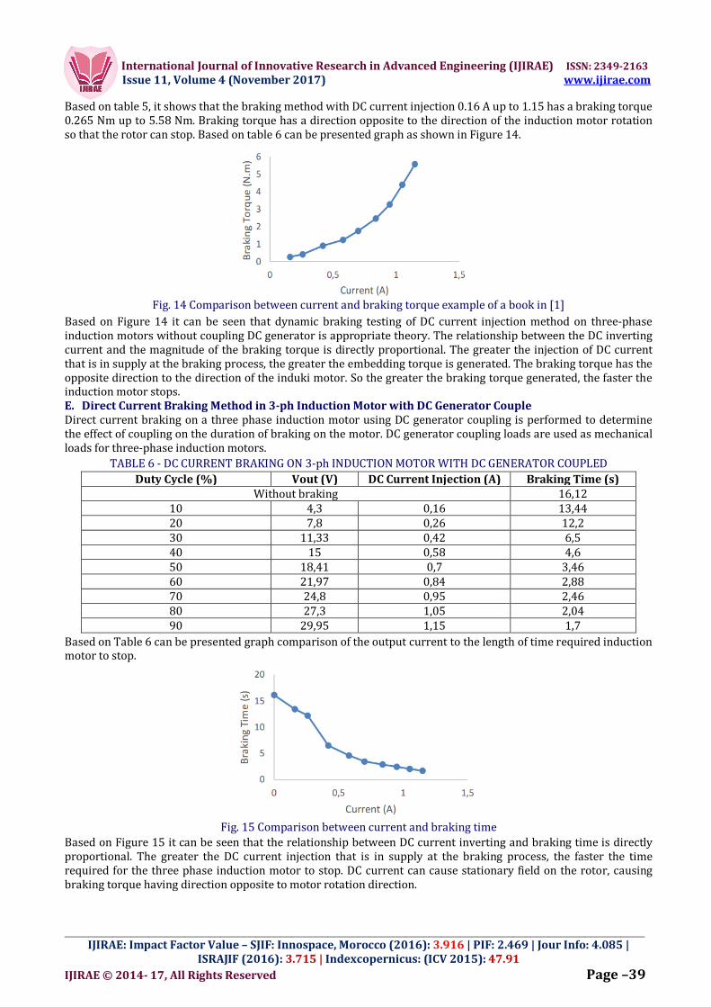
Based on Table 6 can be presented graph comparison of the output current to the length of time required induction motor to stop.
Fig. 15 Comparison between current and braking time
Based on Figure 15 it can be seen that the relationship between DC current inverting and braking time is directly proportional. The greater the DC current injection that is in supply at the braking process, the faster the time required for the three phase induction motor to stop. DC current can cause stationary field on the rotor, causing braking torque having direction opposite to motor rotation direction.

International Journal of Innovative Research in Advanced Engineering (IJIRAE) ISSN: 2349-2163 Issue 11, Volume 4 (November 2017) www.ijirae.com
_________________________________________________________________________________________________ IJIRAE: Impact Factor Value – SJIF: Innospace, Morocco (2016): 3.916 | PIF: 2.469 | Jour Info: 4.085 |
ISRAJIF (2016): 3.715 | Indexcopernicus: (ICV 2015): 47.91 IJIRAE © 2014- 17, All Rights Reserved Page –40
The greater the direct injection current, the stationary field that arises on the stator is greater and causes the rotor to stop faster. The average value of braking torque can be calculated by decreasing the formula in (3). Example of braking torque calculation at 10% duty cycle with injection current value of 0.16A is as follows:
1. Variation of DC injection value of 0,16 A:
bT DC injection 0,16 A =
dTt
j
60201
bT DC injection 0,16 A =
282,06044,13
201495029,0
bT DC injection 0,16 A = 0553,0 N.m Based on the data that has been obtained in the test, it can be seen the braking torque generated at each variation injek DC, such as in table 7.braking torque at 10% duty cycle with the value of injection current 0.16A is as follows: Based on table 7, it can be seen that the braking method with DC current injection 0.16 A to 1.15 has a braking torque of 0.055 Nm up to 2,384 Nm. Braking torque has a direction opposite to the direction of the induction motor rotation so that the rotor can stop. Based on table 7 can be presented graphs as in figure 16. Based on Figure 16 it can be seen that dynamic braking testing of DC current injection method on three phase induction motors when coupled to DC Generator is in theory appropriate. The relationship between the DC inverting current and the magnitude of the braking torque is directly proportional. The greater the injection of DC current that is in supply at the braking process, the greater the embedding torque is generated. The braking torque has the opposite direction to the direction of the induki motor. So the greater the braking torque generated, the faster the induction motor stops.
TABLE 7 - COMPARISON BEETWEN CURRENT INJECTION and BRAKING TORQUE Inject Current (A) Braking Time (second) Braking Torque (N.m)
Without braking 16,22 - 0,16 13,44 0,055 0,26 12,2 0,089 0,42 6,5 0,415 0,58 4,6 0,703 0,7 3,46 1,028
0,84 2,88 1,292 0,95 2,46 1,561 1,05 2,06 1,918 1,15 1,7 2,384
Fig. 16 Comparison between current and braking torque
After testing three-phase induction motor braking under DC Generator coupling and without coupling Generator, then obtained data in the form of motor stop time in two conditions. Figure 17 is a graph of the comparison of the stopping time required for a three phase induction motor under each condition when tested. Based on Figure 17 it can be seen that there are differences in braking time when the motor is on condition without coupled generator and with load coupling generator. Three-phase induction motors require more time to stop when loaded coupling generator. This is because when the induction motor is loaded with a coupling generator, then Motor loading using DC generator also causes the rotor mass to increase. This causes the overall inertial moment value of the engine to increase, so the time required for the induction motor to stop will be longer. The comparison of braking torque generated during braking during the uncoupled conditions of DC Generator and with coupled DC Generator can also be seen in Figure 18. Based on Figure 18 it can be seen that there is a difference in braking torque generated when the motor is in a non-coupled generator condition and with a coupling coupling generator.

International Journal of Innovative Research in Advanced Engineering (IJIRAE) ISSN: 2349-2163 Issue 11, Volume 4 (November 2017) www.ijirae.com
_________________________________________________________________________________________________ IJIRAE: Impact Factor Value – SJIF: Innospace, Morocco (2016): 3.916 | PIF: 2.469 | Jour Info: 4.085 |
ISRAJIF (2016): 3.715 | Indexcopernicus: (ICV 2015): 47.91 IJIRAE © 2014- 17, All Rights Reserved Page –41
Fig. 17 Comparison of braking times when coupled with DC Generator and uncoupled DC Generator.
Fig. 18 Comparison of braking torque when coupled with DC Generator and uncoupled DC Generator.
The braking torque generated at the time of a three-phase induction motor is not coupled to a DC generator greater than when the motor condition is coupled with a DC generator. This is because when the induction motor is loaded with a coupling generator, the loading of the rotor on the motor when coupled to the DC generator also causes the rotor mass to increase. This causes the overall inertial moment value of the engine to increase, so the resulting motor torque is smaller than when the condition is not coupled with a DC generator.
IV. CONCLUSIONS
Based on the measurement and analysis that has been done, it can be concluded that the buck converter has been successfully applied to braking direct injection three-phase induction motor. buck Converter has been successfully created and can produce output voltage which can be changed to smaller than input voltage. , the average value of buck converter efficiency at inductive load is quite high at 25 kHz frequency of 87.50%, buck converter when inductive load is given with minimum duty cycle 10% and frequency 25 kHz gives output voltage equal to 11,3V and output current 0.16A. When operating at a maximum duty cycle of 90% it can provide an output voltage of 29.95V and an output current of 1.15A. In the test result buck converter when applied to braking injection of direct current of three phase induction motor with uncompressed condition of DC generator, when buck converter operate on minimum duty cycle 10% with current output 0,16A,, time required motor to stop is 2, 84 seconds and 0.265 Nm of braking torque. At a maximum 90% duty cyle with an output current of 1.15 A, the required time the motor to stop is 0.19 seconds, with 5,580 N.m of braking torque. The larger the current injection applied to the motor, the greater the resulting braking torque, the faster it will take the motor to stop. Similarly, in direct current injection braking three-phase induction motor with conditions coupled with a DC generator. When the buck converter operates at a minimum duty cycle of 10% with an output current of 0.16, the time required for the motor to stop is 13.44 seconds, with 0.055 N.m of braking torque. At a maximum 90% duty cyle with an output current of 1.15 A, the required time the motor to stop is 1.7 seconds, with torque of 2.384 N.m. The difference in the stop time that occurs in the induction motor when the condition is not coupled with the DC generator is faster than the condition when coupled with the DC generator. This is due to the influence of moment of inertia.
REFERENCES
1. Anantha, M. “Pengereman dinamik pada motor induksi tiga fasa“, Transmisi, Vol 8, No. 1, Juni 2006 2. P.L. Rongmei, Shimi S.L, Dr. S. Chatterji, Vinod K. Sharma. “A Novel fast Braking System for Induction Motor”,
International Journal of Engineering and Innovative Technology (IJEIT) Volume 1, Issue 6, June 2012.

International Journal of Innovative Research in Advanced Engineering (IJIRAE) ISSN: 2349-2163 Issue 11, Volume 4 (November 2017) www.ijirae.com
_________________________________________________________________________________________________ IJIRAE: Impact Factor Value – SJIF: Innospace, Morocco (2016): 3.916 | PIF: 2.469 | Jour Info: 4.085 |
ISRAJIF (2016): 3.715 | Indexcopernicus: (ICV 2015): 47.91 IJIRAE © 2014- 17, All Rights Reserved Page –42
3. Rishabh Singh, Umashankar. S, D. Vijaykumar. “Dynamic braking of induction motor – Analysis of conventional methods and an efficient multistage braking model”. VIT University. Vellore, India. 2005.
4. Wildi, Theodore. ”Electrical Machines, Drives, and Power System”, Prentice Hall Inc, New Jersey. 2002. 5. W.H. Daniel, “Power Electronics,” dalam The McGraw-Hill Companies, Indiana, Valparaiso University, 2011. 6. Zuhal. “Prinsip Dasar Elektroteknik”, Penerbit Gramedia Pustaka Utama, Jakarta, 2004. 7. Rashid, Muhammad H., “Power Electronics Handbook“, University of Florida, Florida, 2001. 8. G.K. Dubey, “Fundamentals of Electric Drive”, Narosa Publishing House, 1995. 9. Hindmarsh, John. “Electrical Machines and Drive Systems Third Edition”, Newnes, Woburn MA. 2002. 10.Masihin, Elvys Hirsley Anthon. “Pemoelan dan Simulasi Pengereman Dinamik Motor Induksi Tiga Fasa”, Jakarta,
2008 11.Chapman, Stephen J.“Electric Machinery Fundamentals”, Second Edition Mc Graw Hill Companies, Singapore,
1991. 12.Fitzgerald, A.E.“Electric Machinery”, Sixth Edition Mc Graw Hill Companies, Americas, 2003.