From Halfspace M-depth to Multiple-output Expectile Regression

1
Abstract The results of subsoil-structure interaction analyses can be different and depend on the choice of the interaction model. These models are being continuously improved. The analysis of the interaction between the steel-fibre reinforced concrete slab and subsoil was carried out by means of three-dimensional finite element analysis. This interaction was also observed during the loading test in the experimental measurements. Soil is generally heterogeneous, hence its properties are different from the idealized behaviour of the linear elastic isotropic homogeneous material. The modulus of deformability of the modelled area of subsoil varies continuously with increasing depth. The inhomogeneous half-space was used for the modelling. In the parametric study, presented here, the deformations obtained from the analysis of the homogeneous and inhomogeneous half-spaces were compared. The values calculated from the three dimensional finite element interaction models of the subsoil were compared with the values measured during the loading test. Keywords: subsoil-structure interaction, finite element, foundation structures, inhomogeneous half-space, homogeneous half-space.
1 Introduction The complexity of the static solution of foundation structures is associated with several aspects, which play important roles in the calculations. This includes, amount others, the choice of the computational model. The computational interaction models are becoming increasingly sophisticated. Results of the solutions may be different and depend on the choice of the model of the subsoil. The influence of the physically-nonlinear behaviour of the structure and interaction between the upper structure and foundation are the other aspects which influence the results of the subsoil-structure interaction analysis. Distribution of contact stress at the foundation base is also influenced by the interaction of the foundation and subsoil.
Paper 9 Application of an Inhomogeneous Halfspace for the Solution of Foundation-Subsoil Interaction based on the Finite Element Method J. Labudkova and R. Cajka Department of Structures, Faculty of Civil Engineering VŠB – Technical University of Ostrava Ostrava-Poruba, Czech Republic
Civil-Comp Press, 2015 Proceedings of the Fifteenth International Conference on Civil, Structural and Environmental Engineering Computing, J. Kruis, Y. Tsompanakis and B.H.V. Topping, (Editors), Civil-Comp Press, Stirlingshire, Scotland
2
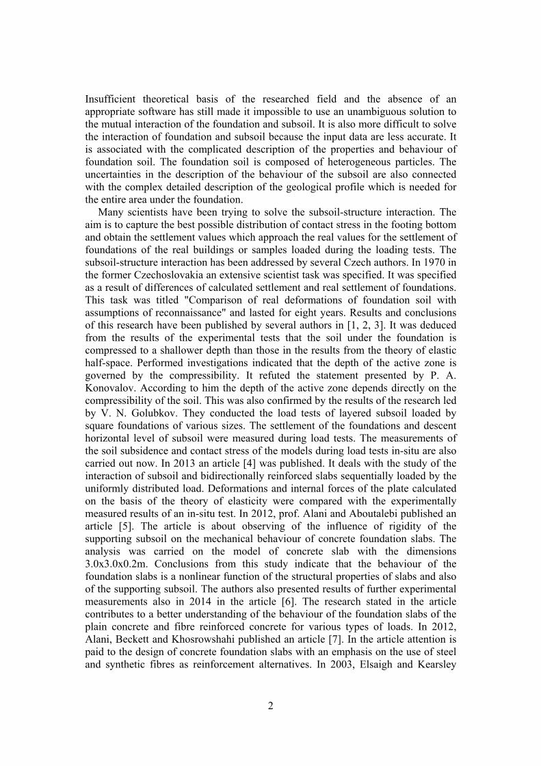
Insufficient theoretical basis of the researched field and the absence of an appropriate software has still made it impossible to use an unambiguous solution to the mutual interaction of the foundation and subsoil. It is also more difficult to solve the interaction of foundation and subsoil because the input data are less accurate. It is associated with the complicated description of the properties and behaviour of foundation soil. The foundation soil is composed of heterogeneous particles. The uncertainties in the description of the behaviour of the subsoil are also connected with the complex detailed description of the geological profile which is needed for the entire area under the foundation.
Many scientists have been trying to solve the subsoil-structure interaction. The aim is to capture the best possible distribution of contact stress in the footing bottom and obtain the settlement values which approach the real values for the settlement of foundations of the real buildings or samples loaded during the loading tests. The subsoil-structure interaction has been addressed by several Czech authors. In 1970 in the former Czechoslovakia an extensive scientist task was specified. It was specified as a result of differences of calculated settlement and real settlement of foundations. This task was titled "Comparison of real deformations of foundation soil with assumptions of reconnaissance" and lasted for eight years. Results and conclusions of this research have been published by several authors in [1, 2, 3]. It was deduced from the results of the experimental tests that the soil under the foundation is compressed to a shallower depth than those in the results from the theory of elastic half-space. Performed investigations indicated that the depth of the active zone is governed by the compressibility. It refuted the statement presented by P. A. Konovalov. According to him the depth of the active zone depends directly on the compressibility of the soil. This was also confirmed by the results of the research led by V. N. Golubkov. They conducted the load tests of layered subsoil loaded by square foundations of various sizes. The settlement of the foundations and descent horizontal level of subsoil were measured during load tests. The measurements of the soil subsidence and contact stress of the models during load tests in-situ are also carried out now. In 2013 an article [4] was published. It deals with the study of the interaction of subsoil and bidirectionally reinforced slabs sequentially loaded by the uniformly distributed load. Deformations and internal forces of the plate calculated on the basis of the theory of elasticity were compared with the experimentally measured results of an in-situ test. In 2012, prof. Alani and Aboutalebi published an article [5]. The article is about observing of the influence of rigidity of the supporting subsoil on the mechanical behaviour of concrete foundation slabs. The analysis was carried on the model of concrete slab with the dimensions 3.0x3.0x0.2m. Conclusions from this study indicate that the behaviour of the foundation slabs is a nonlinear function of the structural properties of slabs and also of the supporting subsoil. The authors also presented results of further experimental measurements also in 2014 in the article [6]. The research stated in the article contributes to a better understanding of the behaviour of the foundation slabs of the plain concrete and fibre reinforced concrete for various types of loads. In 2012, Alani, Beckett and Khosrowshahi published an article [7]. In the article attention is paid to the design of concrete foundation slabs with an emphasis on the use of steel and synthetic fibres as reinforcement alternatives. In 2003, Elsaigh and Kearsley
3
published an article [29]. The article is focused on assessing of the influence of ductility on the bearing capacity of foundation concrete slabs reinforced with steel fibres. Comparison of deformation behaviour of concrete slabs reinforced with steel fibres and slabs of plain concrete is described in [9].
Currently the experimental measurements of stress and strain of foundation structures in connection with the subsoil-structure interaction are also conducted at the Department of Structures, Faculty of Civil Engineering, VSB - TU Ostrava. Other fields of research are focused on the use of sliding joints to eliminate friction between the foundation and subsoil [10, 11] and prestressing of foundation structures [12] (the numerical solution). At the Faculty of Civil Engineering, an unique test equipment was constructed in order to measure the shear resistance of the sample from asphalt belts. During testing of the asphalt belts the shear resistance of the sample depending on the temperature is measured in a climatic chamber. The process, results and conclusions of tests are described in detail in [10, 13]. In 2010, the construction of test equipment called Stand was performed at the Faculty of Civil Engineering [14]. The test equipment allows experimental measurement of deformation and stress and stress-strain relations can be observed in connection with the subsoil-structure interaction. The process, results and conclusions of tests are described in detail in [15, 16, 17, 18].
2 FEM analyses of an elastic half-space
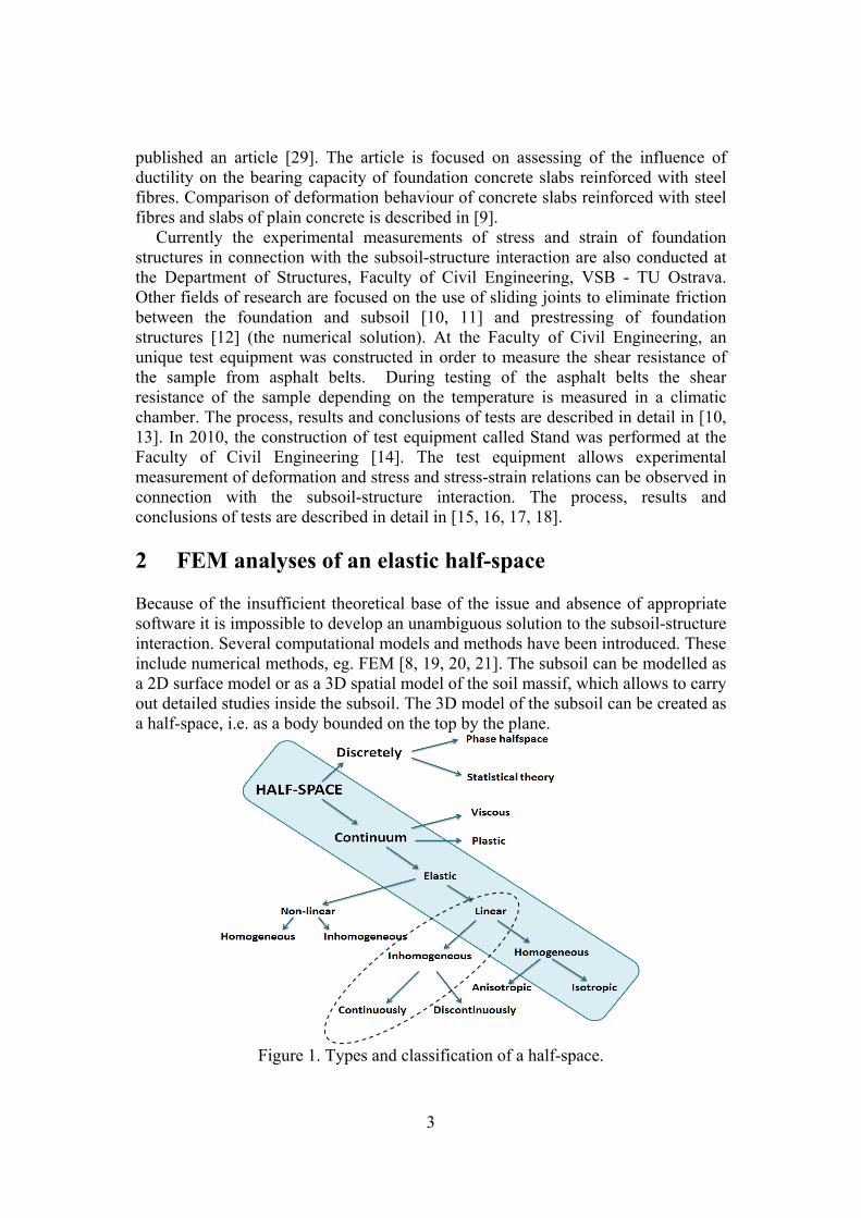
Because of the insufficient theoretical base of the issue and absence of appropriate software it is impossible to develop an unambiguous solution to the subsoil-structure interaction. Several computational models and methods have been introduced. These include numerical methods, eg. FEM [8, 19, 20, 21]. The subsoil can be modelled as a 2D surface model or as a 3D spatial model of the soil massif, which allows to carry out detailed studies inside the subsoil. The 3D model of the subsoil can be created as a half-space, i.e. as a body bounded on the top by the plane.
Figure 1. Types and classification of a half-space.
4
2.1 The homogeneous elastic continuum
The subsoil is created by a body bounded on the top by the plane. The simplest idealization of the half-space is an elastic homogeneous isotropic body comprised of substance for which Hooke's law is valid and it is dependent on two material parameters. These are the elastic modulus and Poisson's ratio. According to the assumptions of elastic half-space the deformations do not undermine continuity of the half-space, and the law of superposition is valid. For simple types of loads the analytic relations of calculations of deformation and stress can be derived for such a half-space. For example, the equations for calculation of the component of the pressure stress σz have been derived for a point lying in any depth below the top of the rectangular load area. This was derived by several authors between 1934 and 1939.
The size of the modelled area representing the subsoil, choice of boundary conditions and the size of the finite-element mesh is difficult to be determined correctly during the creation of the spatial model using 3D elements. Dependence on those parameters was proved by parametric studies in [22, 23]. Due the heterogeneity of the soil, its properties are different from idealization of the linear elastic isotropic homogeneous material. The calculated values of the subsidence do not correspond to the measured values of foundation subsidence of existing buildings, or values measured during the experiments [22, 23].
2.2 The inhomogeneous elastic continuum The modulus of deformability of the subsoil varies continuously with the increasing depth. It was solved using the inhomogeneous half-space. In the inhomogeneous half-space there is a different concentration of the vertical stress in the axis of the foundation than that in the homogeneous half-space.
The equation (1) for calculation of the vertical component of the stress was derived for the half-space loaded on the surface by force (Boussinesq´s task). The concentration factor is introduced into the calculations of the inhomogeneous half-space [24]:
RR
Pzz 22 (1)
The equation (2) based on the minimum of deformation work was derived by
Frölich. In case =3 it is isotropic an elastic half-space (E=const.). If =4 it is a half-space whose modulus of deformability increases with the depth:
m
def zEE 0 (2)
21
m (3)

5
where E0 – modulus of elasticity at the surface z – z-coordinate (depth) m – coefficient depending on Poisson's ratio The use of the inhomogeneous half-space is also discussed in articles [25, 26].
The author of the article [25] introduces the equation for displacements in the inhomogeneous half-space outside of the loaded area in connection with displacements inside the loaded area.
3 Three-dimensional numerical model 3.1 Experimental loading test The analysis of the interaction of the concrete slab and subsoil was carried in the software Ansys 15.0. This interaction was also monitored during the loading test in the experimental measurements. For a loading test an unique equipment was used. The equipment was built in the Faculty of Civil Engineering, VŠB - Technical university of Ostrava [14]. Another experimental measurements and results are also reported in [5, 6, 17, 27]. The test sample for the task was a steel-fibre concrete foundation slab [15, 28]. The steel-fibre concrete foundation slab had dimensions of 2000x2000x170mm (Figure 2). The concrete C25/30 was used there. The fibre reinforcement was consisted of steel fibres type 3D DRAMIX 65/60B6 - 25 kg.m-3.
The simple foundation conditions are there from a geological point of view. The top layer of subsoil is made up of loess loams with the consistency class F4 and its thickness is about 5 m. The soil was described with the specific weight =18.5 kNm-3, Poisson's ratio =0.35 and modulus of deformability Edef,2=23.7 MPa.
Figure 2: Concreting of the steel-fibre concrete slab and loading test.
6
The steel-fibre concrete foundation slab was loaded by the pressure exerted by hydraulic press during the experimental loading test. The dimensions of the loaded area in the centre of the slab were 200x200mm. The loading was increased of piecewise, 20kN/60min (Figure 2).
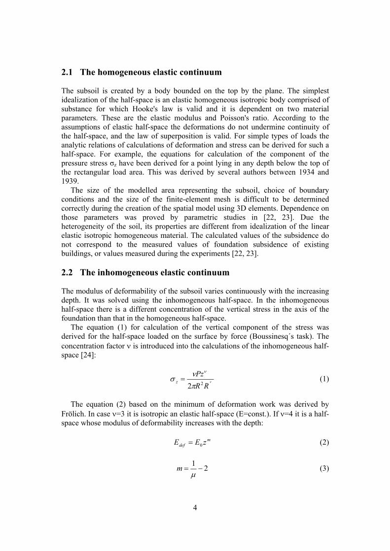
The maximum anticipated load was calculated as 83kN. Despite the assumptions the slab did not fail even after nine cycles. Even with the load of 180kN the slab did not fail. The test was discontinued. During the repeated loading test of the steel-fibre concrete foundation slab the 50 kN/30 min cycle was chosen for the loading. The slab failed during the sixth loading cycle (Figure 3). The value of the load was 250kN. The slab was failed by punching.
Figure 3: Cracks on the lower surface of the slab after its failure.
3.2 The 3D numerical model of an inhomogeneous elastic
continuum The computational model was created using the 2D and 3D finite elements. The steel-fibre concrete slab was created using the 2D elements SHELL 181. The thickness of the slab was additionally defined to the element SHELL 181. The thickness was 170mm. The model of the subsoil was created using the 3D elements SOLID 45. After that, the required properties of materials of modelled slab and subsoil were added. The material No. 1 was marked concrete with the modulus E=29.0GPa and Poisson coefficient =0.2. The subsoil was divided into 30 layers, where the inhomogeneity of the subsoil was considered by the increasing Edef. The soil has been characterised with the material number 2-31 and the Poisson's ratio =0.35. The self weight of the soil massif and concrete slab had been neglected during the solution of the task. The model was created as a cube with dimensions 6.0x6.0x6.0m. The thickness of one layer of the subsoil model was 0.2m. The modulus of deformability begins at the surface of the model with value

7
Edef=23.7MPa. This value progressively increases through layers (Figure 4) of the formula: 4...0 FigureseezEE m
def (4)
857.0235.0
12
1
m (5)
Figure 4: Layers of the inhomogeneous half-space elastic continuum.
The slab was created using 4 keypoints. All layers of subsoil model were created
using 132 keypoints. The keypoints were connected by lines. The areas were created from the lines and the volumes were, in turn, created from those areas. The volumes of the individual layers have different properties according to the table in Figure 4. The 3D finite elements forming the mesh had a dimension 0.1x0.1x0.1m. The size of the 2D finite-element mesh for the modelled area of the slab was 0.1x0.1m. The both finite-element meshes were regular. The load was distributed into the nodes under the load area which had the size of 200x200mm. The load was approximately 250kN at the time when the sample failed. This value was also used in creation of a numerical model.
It is necessary to define the contact area so that the effects of the load on the slab could be transferred to the soil. The finite-element model was solved through contact elements. The contact is made by a contact pair TARGE 170 and CONTA 173. The interaction between the foundation and subsoil is always described by the nonlinear analysis due to structural nonlinearities. This structural nonlinearity is caused by the contact task and unilateral bond, which acts only in compression. The analysis requires an iterative solution. The system behaviour is dependent on whether both parts of the interaction model are in contact or not. The influence of friction between the slab and subsoil was neglected. The coefficient of
8
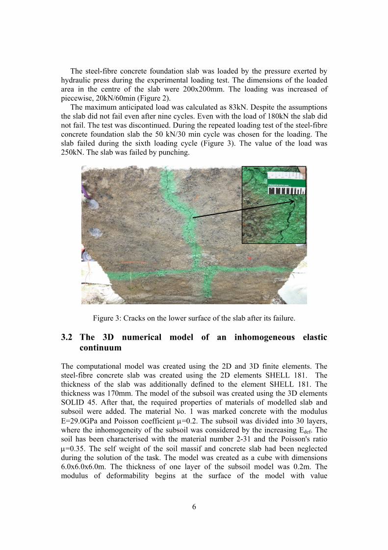
friction is thus zero. After the contact is established, it is necessary to verify that the normals of the both contact surfaces have opposite direction, or they should be turned in order to be in the opposite direction (Figure 5).
Figure 5: Contact area and normals of the both contact surfaces.
The boundary conditions disable all horizontal displacements in the external
walls of the modelled area representing the subsoil as well as all vertical displacements in the level of the bottom base of model. The boundary conditions did not disable the displacement of nodes in the level of the upper base of model which represents the terrain.
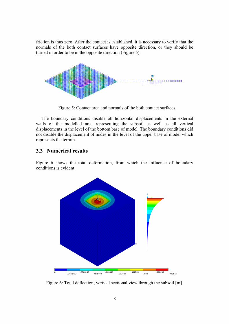
3.3 Numerical results Figure 6 shows the total deformation, from which the influence of boundary conditions is evident.
Figure 6: Total deflection; vertical sectional view through the subsoil [m].

9
The vertical component of the stress σz in the subsoil is plotted in Figure 7. Red areas show the biggest tensile stresses of subsoil in the area of the settlement trough. Figure 7 shows σz depending on the increasing depth in the vertical section through the centre of the subsoil led from the top surface to the bottom. Figure 8 shows the distribution of contact stress.
Figure 7: Component of the stress σz; sectional view through the subsoil [Pa].
Figure 8: Distribution of contact stress [Pa].

10
As expected there the contact stress is concentrated around the edge of the concrete slab and in its corners, where the stress increases (Figure 8). It is also visible in the transverse and diagonal sectional views through the slab. Stress peaks which represent the increasing values of the contact stress can be limited in Ansys. 4 Comparison of the homogeneous and inhomogeneous
elastic half-spaces 168 varieties of the 3D models of the linear homogeneous isotropic continuum were created and compared in a parametric study referred to in the articles [16, 23]. These models differed in their boundary conditions, in the size of the finite-element mesh and in the size of modelled area. These are the parameters which have a significant impact on the resulting deformation, internal forces and contact stress. The parametric study [16, 23] proved the predominant influence of the depth of subsoil model on the resulting deformations. In case of the homogeneous isotropic linear continuum, the deformation increases depending on the increasing depth of the subsoil model. With the increasing depth of subsoil model the difference also increases between the calculated deformations for individual variants of boundary conditions. The choice of the boundary conditions becomes thus more important with the increasing depth as it influences the resulting vertical deformation [16, 23]. These assertions were also verified for the steel-fibre concrete slab. 12 different numerical 3D models of the linear homogeneous isotropic continuum were created for the steel-fibre concrete slab. The resulting deformations confirmed all conclusions of the parametric study published in [16, 23]. The models of the linear homogeneous isotropic continuum do not reflect the structural strength of the soil.
In reality, the properties of the subsoil vary with the depth. This is possible to take into account by use of inhomogeneous continuum. Modulus of deformability increases with depth of inhomogeneous continuum. Attention was also paid to the dependence of the resulting vertical deformations on the changing depth of the subsoil model. This dependence was proved for three different variants of the boundary conditions (Figure 9).
Figure 9: Three different variants of boundary conditions [Pa].
11
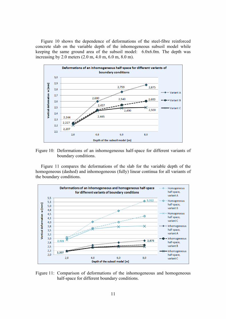
Figure 10 shows the dependence of deformations of the steel-fibre reinforced concrete slab on the variable depth of the inhomogeneous subsoil model while keeping the same ground area of the subsoil model: 6.0x6.0m. The depth was increasing by 2.0 meters (2.0 m, 4.0 m, 6.0 m, 8.0 m).
Figure 10: Deformations of an inhomogeneous half-space for different variants of
boundary conditions.
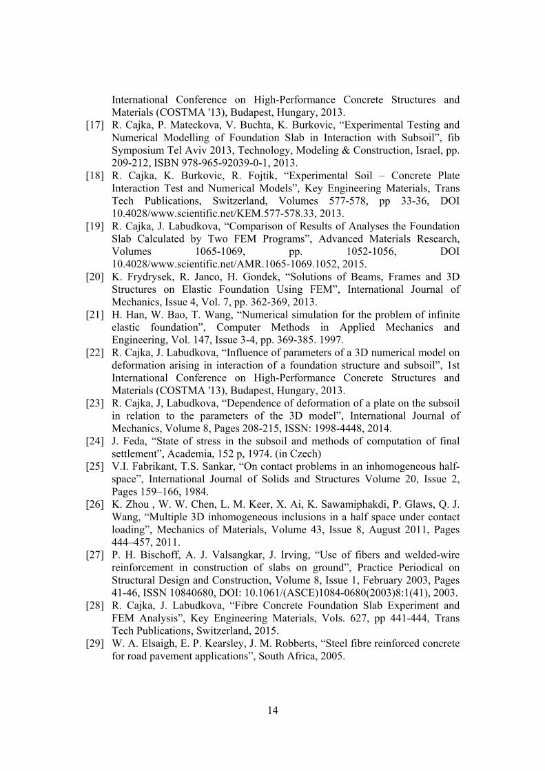
Figure 11 compares the deformations of the slab for the variable depth of the homogeneous (dashed) and inhomogeneous (fully) linear continua for all variants of the boundary conditions.
Figure 11: Comparison of deformations of the inhomogeneous and homogeneous
half-space for different boundary conditions.

12
5 Conclusion The model of the inhomogeneous continuum provides smaller vertical deformations than the model of the homogeneous continuum. This is evident from the graph in Figure 11. This is a consequence of the modulus of deformability which increases with the depth.
The graph also shows that the resulting deformations which were calculated from the inhomogeneous continuum model do not depend so much on the randomly chosen geometric model parameters of the subsoil as those deformations which were calculated from the homogeneous continuum. The increasing depth of the subsoil model was the geometric parameter which has been observed in this paper. The difference between the smallest and the largest values of the resulting vertical deformation in the middle of the steel-fibre concrete slab in the homogeneous subsoil model is 2.93mm, while the difference between the smallest and the largest values of the resulting vertical deformations in the inhomogeneous subsoil model is 0.67mm. The difference in values is about 360% for the geometrically identical models which were different only in the homogeneity / inhomogeneity of the subsoil model. This means that the inhomogeneous continuum provides more stable results which are significantly less affected by the choice of the geometry and dimensions of the area representing the subsoil. The deformations calculated in the homogeneous subsoil model are larger on average by 54% than those calculated in the inhomogeneous subsoil model.
The inhomogeneous model with the dimensions 6.0x6.0x6.0m and the boundary conditions of the variant B calculated the subsidence of 2.572mm - this is only by 10% less than the really subsidence of 2.83mm measured during loading test.
Acknowledgment This outcome has been achieved with the financial support by Student Grant Competition VSB-TUO. Project registration number is SP2015/108.
References [1] J. Feda, “Engineering aspects of soil rheology”, Inženýrské stavby 5/1989, str.
221-24, 1989. (in Czech) [2] J. Feda, “Surface model of foundation soil in terms of geomechanics”,
Inženýrské stavby 9/1989, str. 43-430, 1989. (in Czech) [3] J. Havlíček, “Settlement of foundations of flat founded buildings”, Inženýrské
stavby 7/1982, str. 34-340, 1982. (in Czech) [4] X. Huang, X. Liang, M. Liang, M. Deng, A. Zhu, Y. Xu, X. Wang, Y. Li,
“Experimental and theoretical studies on interaction of beam and slab for cast-in-situ reinforced concrete floor structure”, Journal of Building Structures / Jianzhu Jiegou Xuebao, Vol. 34, No. 5, pp. 63-71, 2013.

13
[5] A. Alani, M. Aboutalebi, “Analysis of the subgrade stiffness effect on the behaviour of ground-supported concrete slabs” Structural Concrete, Issue 13, Volume 2, pages 102-108, DOI: 10.1002/suco.201100043, 2012.
[6] M. Aboutalebi, A. Alani, J. Rizzuto, D. Beckett: “Structural behaviour and deformation patterns in loaded plain concrete ground-supported slabs”, Structural Concrete, Issue 15, Volume 1, pages 81-93. ISSN 1464-4177, DOI 10.1002/suco.201300043, 2014.
[7] A. Alani, D. Beckett, F. Khosrowshahi, “Mechanical behaviour of a steel fibre reinforced concrete ground slab, Magazine of Concrete Research”, Volume 64, Issue 7, July 2012, Pages 593-604, ISSN 00249831, DOI: 10.1680/macr.11.00077, 2012.
[8] R. Cajka, “Numerical Solution of Temperature Field for Stress Analysis of Plate Structures”, Applied Mechanics and Materials, Vol. 470 (2014), pp 177-187. Trans Tech Publications, Switzerland, ISSN: 16609336, ISBN: 978-3-03785-961-2, doi:10.4028/www.scientific.net/AMM.470.177, 2014.
[9] D. Beckett, “Comparative tests on plain, fabric reinforced and steel fibre-reinforced concrete ground slabs”, Concrete (London), Volume 24, No. 3. 1989.
[10] M. Janulikova, “Behavior of selected materials to create sliding joint in the foundation structure”, Advanced Materials Research, Volume 838-841, Pages 454-457, 2nd Global Conference on Civil, Structural and Environmental Engineering, GCCSEE 2013; Shenzhen; China; 28 September 2013 through 29 September 2013, ISSN: 10226680 ISBN: 978-303785926-1, DOI: 10.4028/www.scientific.net/AMR.838-841.454, 2014.
[11] M. Janulikova, P. Mynarcik, “Modern sliding joints in foundations of concrete and masonry structures”, International Journal of Mechanics, Vol. 8, Issue 1, Pages 184-189. 2014
[12] P. Mynarcik, "The Subsidence Analysis of Experimental Post-Tensioned Concrete Slab Model in the Course of the Static Load Test", Applied Mechanics and Materials, Vols 744-746, pp. 1556-1559, DOI 10.4028/www.scientific.net/AMM.744-746.1556, 2015.
[13] R. Cajka, P. Mateckova, M. Janulikova, “Bitumen Sliding Joints for Friction Elimination in Footing Bottom”, Applied Mechanics and Materials, Volume 188, (2012), pp. 247-252, ISSN: 1660-9336, ISBN: 978-303785452-5, DOI:10.4028/www.scientific.net/AMM.188.247, 2012.
[14] R. Cajka, V. Krivy, D. Sekanina, “Design and Development of a Testing Device for Experimental Measurements of Foundation Slabs on the Subsoil”. Transactions of the VSB - Technical University of Ostrava, Construction Series, Volume XI, Number 1/2011, VSB - TU Ostrava, Pages 1–5, ISSN (Online) 1804-4824, ISSN (Print) 1213-1962, 2011.
[15] V. Buchta, P. Mynarcik, “Experimental testing of fiber concrete foundation slab model”, 3rd International Conference on Civil Engineering and Transportation, ICCET 2013Applied Mechanics and Materials. Volume 501-504, pp. 291-293, DOI 10.4028/www.scientific.net/AMR.1020.227, 2014.
[16] R. Cajka, J. Labudkova, “Influence of parameters of a 3D numerical model on deformation arising in interaction of a foundation structure and subsoil”, 1st
14
International Conference on High-Performance Concrete Structures and Materials (COSTMA '13), Budapest, Hungary, 2013.
[17] R. Cajka, P. Mateckova, V. Buchta, K. Burkovic, “Experimental Testing and Numerical Modelling of Foundation Slab in Interaction with Subsoil”, fib Symposium Tel Aviv 2013, Technology, Modeling & Construction, Israel, pp. 209-212, ISBN 978-965-92039-0-1, 2013.
[18] R. Cajka, K. Burkovic, R. Fojtik, “Experimental Soil – Concrete Plate Interaction Test and Numerical Models”, Key Engineering Materials, Trans Tech Publications, Switzerland, Volumes 577-578, pp 33-36, DOI 10.4028/www.scientific.net/KEM.577-578.33, 2013.
[19] R. Cajka, J. Labudkova, “Comparison of Results of Analyses the Foundation Slab Calculated by Two FEM Programs”, Advanced Materials Research, Volumes 1065-1069, pp. 1052-1056, DOI 10.4028/www.scientific.net/AMR.1065-1069.1052, 2015.
[20] K. Frydrysek, R. Janco, H. Gondek, “Solutions of Beams, Frames and 3D Structures on Elastic Foundation Using FEM”, International Journal of Mechanics, Issue 4, Vol. 7, pp. 362-369, 2013.
[21] H. Han, W. Bao, T. Wang, “Numerical simulation for the problem of infinite elastic foundation”, Computer Methods in Applied Mechanics and Engineering, Vol. 147, Issue 3-4, pp. 369-385. 1997.
[22] R. Cajka, J. Labudkova, “Influence of parameters of a 3D numerical model on deformation arising in interaction of a foundation structure and subsoil”, 1st International Conference on High-Performance Concrete Structures and Materials (COSTMA '13), Budapest, Hungary, 2013.
[23] R. Cajka, J, Labudkova, “Dependence of deformation of a plate on the subsoil in relation to the parameters of the 3D model”, International Journal of Mechanics, Volume 8, Pages 208-215, ISSN: 1998-4448, 2014.
[24] J. Feda, “State of stress in the subsoil and methods of computation of final settlement”, Academia, 152 p, 1974. (in Czech)
[25] V.I. Fabrikant, T.S. Sankar, “On contact problems in an inhomogeneous half-space”, International Journal of Solids and Structures Volume 20, Issue 2, Pages 159–166, 1984.
[26] K. Zhou , W. W. Chen, L. M. Keer, X. Ai, K. Sawamiphakdi, P. Glaws, Q. J. Wang, “Multiple 3D inhomogeneous inclusions in a half space under contact loading”, Mechanics of Materials, Volume 43, Issue 8, August 2011, Pages 444–457, 2011.
[27] P. H. Bischoff, A. J. Valsangkar, J. Irving, “Use of fibers and welded-wire reinforcement in construction of slabs on ground”, Practice Periodical on Structural Design and Construction, Volume 8, Issue 1, February 2003, Pages 41-46, ISSN 10840680, DOI: 10.1061/(ASCE)1084-0680(2003)8:1(41), 2003.
[28] R. Cajka, J. Labudkova, “Fibre Concrete Foundation Slab Experiment and FEM Analysis”, Key Engineering Materials, Vols. 627, pp 441-444, Trans Tech Publications, Switzerland, 2015.
[29] W. A. Elsaigh, E. P. Kearsley, J. M. Robberts, “Steel fibre reinforced concrete for road pavement applications”, South Africa, 2005.