Application of a Design Method for Manufacture and...
113
Application of a Design Method for Manufacture and Assembly Flexible Assembly Methods and their Evaluation for the Construction of Bridges Master of Science Thesis in the Master’s Programme Design and Construction Project Management MICHEL KALYUN TEZERA WODAJO Department of Civil and Environmental Engineering Division of Structural Engineering Steel and Timber Structures CHALMERS UNIVERSITY OF TECHNOLOGY Göteborg, Sweden 2012 Master’s Thesis 2012:29
Transcript of Application of a Design Method for Manufacture and...

Application of a Design Method for
Manufacture and Assembly Flexible Assembly Methods and their Evaluation for the
Construction of Bridges
Master of Science Thesis in the Master’s Programme Design and Construction
Project Management
MICHEL KALYUN
TEZERA WODAJO
Department of Civil and Environmental Engineering
Division of Structural Engineering
Steel and Timber Structures
CHALMERS UNIVERSITY OF TECHNOLOGY
Göteborg, Sweden 2012
Master’s Thesis 2012:29


MASTER’S THESIS 2012:29
Application of a Design Method for
Manufacture and Assembly
Master of Science Thesis in the Master’s Programme Design and Construction
Project Management
MICHEL KALYUN & TEZERA WODAJO
Department of Civil and Environmental Engineering
Division of Structural Engineering
Steel and Timber Structures
CHALMERS UNIVERSITY OF TECHNOLOGY
Göteborg, Sweden 2012

Application of a Design Method for Manufacture and Assembly
Flexible Assembly Methods and their Evaluation for the Construction of Bridges
Master of Science Thesis in the Master’s Programme Design and Construction
Project Management
MICHEL KALYUN & TEZERA WODAJO
© MICHEL KALYUN & TEZERA WODAJO, 2012
Examensarbete/Institutionen för bygg- och miljöteknik,
Chalmers tekniska högskola 2012:29
Department of Civil and Environmental Engineering
Division of Construction Management
Chalmers University of Technology
SE-412 96 Göteborg
Sweden
Telephone: + 46 (0)31-772 1000
Cover:
Demonstration of easy assembly
Chalmers reproservice / Department of Civil and Environmental Engineering
Göteborg, Sweden 2012

I
Application of a Design Method for Manufacture and Assembly
Flexible Assembly Methods and their Evaluation for the Construction of Bridges
Flexible Assembly Methods and their Evaluation for the
Construction of Bridges
Master of Science Thesis in the Master’s Programme Design and Construction
Project Management
MICHEL KALYUN & TEZERA WODAJO
Department of Civil and Environmental Engineering
Division of Construction Management
Chalmers University of Technology
ABSTRACT
The core of this thesis work is formulated by tasks of identification, rationalization
and evaluation of technical solutions, bridge concepts and assembly methods being
used in other sectors. The concept of Design for Manufacturing and Assembly
(DFMA) will be applied for the evaluation of these flexible assembly techniques and
bridge concepts. In order for this to happen, this paper primarily lays a theoretical
background of the concept of DFMA and criteria that need to be fulfilled in the
successful implementation of the system. These DFMA requirements are further
processed together with parameters that are bridge specific for realization of a more
consolidated set of general DFMA criteria that are adaptive to the construction and/or
installation of bridges. The general DFMA criteria are then studied from a
manufacturing and assembly perspective which yields characteristics that belong to
each block. By tracing the properties of the said manufacturing and assembly
characteristics, goals set by project PANTURA are expressed in terms of their
respective manufacturing and assembly characteristics. The criteria prescribed under
each PANTURA indicators are then utilized as basis for qualitative evaluation of
assembly methods and bridge technical concepts, presentation of which form part of
the research work. Evaluation of each assembly techniques and bridge concepts has
been done according to the extent to which they fulfil the PANTURA goals.
During the course of the work certain difficulties that are inherent in the nature of the
construction industry and context of the work are also traced and remarks are made on
them. Further studies on this topic can be conducted by limiting the subject according
to parties involved in the overall construction process and/or work methodologies that
are followed on-site.
Key words: design decision support tools, design methods, bridge construction,
industrial thinking, Design for Manufacturing and Assembly, criteria,
knowledge transfer, evaluation, PANTURA indicators

II
Applicering av Design Metod för Tillverkning och Montering
Flexibla monteringsmetoder och deras utvärdering för brobyggande
Examensarbete inom Design and Construction Project Management
MICHEL KALYUN & TEZERA WODAJO
Institutionen för bygg- och miljöteknik
Avdelningen för Construction Management
Chalmers tekniska högskola
SAMMANFATTNING
Kärnan av detta examensarbete består utav uppgiftsidentifiering, rationalisering och
utvärdering av tekniska koncept, brokoncept och monteringsmetoder brukade i andra
industrier. Konceptet Design for Manufacturing and Assembly (DFMA) kommer att
tillämpas för utvärdering av dessa flexibla monteringstekniker och brokoncept. För att
göra detta genomförbart, kommer det i första hand ett utlägg av den teoretiska
bakgrunden för begreppet DFMA att genomföras och de kriterier som krävs för en
lyckad applicering av systemet. Dessa kriterier kommer att tillsammans med
parametrar specifika för brokonstruktion att bearbetas och genomgå en
förverkligandet av en ny uppsättning generella DFMA kriterier som är anpassade till
byggande och/eller uppförande av broar. De generella DFMA kriterierna är därefter
studerade ur tillverkning- och monteringsaspekter för att i enlighet med deras
egenskaper delas upp i de två perspektiven. Genom att spåra egenskaperna för
tillverkning- och monteringskaraktärer, kan de vidare användas vid tilldelning för de
indikatorer som projektet PANTURA har satt upp i enlighet med deras uppsatta mål.
De kriterier som föreskrivs under varje PANTURA indikator används sedan som
underlag för kvalitativ utvärdering av monteringsmetoder och brotekniska koncept, en
presentation som är del av detta arbete. Utvärderingen av varje monteringsteknik och
brokoncept har gjorts i enlighet med den utsträckning som uppfyller PANTURA
målen.
Under arbetets gång har vissa svårigheter naturliga till byggindustrin och
omfattningen av arbetet uppdagats, vidare uppmärksammats och kommenterats.
Fortsatta studier inom temat kan utföras genom att begränsa ämnet efter parter
involverade i den övergripande byggprocessen och/eller de arbetsmetoder som följs
på byggarbetsplatserna.
Nyckelord: beslutsverktyg för konstruktioner, design metoder, brokonstruktioner,
industriellt tänkande, Design for Manufacturing and Assembly,
montering, kriterier, kunskapsöverföring, utvärdering, PANTURA
indikatorer

CHALMERS Civil and Environmental Engineering, Master’s Thesis 2012:29 III
Contents
1 INTRODUCTION 1
1.1 PANTURA project 1
1.2 Concurrent Engineering, Lean Manufacturing and Design decision support
tools 2
1.3 Background 4
1.4 Purpose and objectives 4
1.5 Method 4
1.6 Scope and limitations 5
2 THE CONCEPT OF DESIGN FOR MANUFACTURING AND ASSEMBLY
(DFMA) 7
2.1 Defining DFMA 7
2.2 Why DFMA – benefits and challenges 11
2.2.1 Benefits 12
2.2.2 Challenges 14
2.3 DFMA: state of the art in various industries 14
2.3.1 DFMA and advanced manufacturing technologies 15
2.3.2 Application of DFMA in different industries 17
2.4 General DFMA criteria 19
2.5 DFMA: state of the art in the construction industry 22
3 DFMA CRITERIA AND PANTURA INDICATORS 27
3.1 PANTURA indicators in bridge construction 27
3.2 DFMA translation of PANTURA indicators 27
3.2.1 Characterization of the general DFMA criteria 28
3.2.2 Translation of the PANTURA indicators 30
a. Mobility 31
b. Lifecycle cost 32
c. Time 35
d. Worker safety during construction 38
e. Safety of residents 41
f. Noise disturbance 42
g. Dust emissions 43
h. Greenhouse gas (GHG) emissions 44
i. Energy use 46
j. Waste reduction/recycling 47
4 REVIEW OF INDUSTRIALIZED ASSEMBLY METHODS 51
4.1 ConXtech structural steel space frame systems 51
4.1.1 On-site assembly techniques for composite FRP-steel bridges 54
CHALMERS, Civil and Environmental Engineering, Master’s Thesis 2012:29 IV
a. Technical concept 1: Snap-fit connection between FRP deck and steel
girders 54
b. Technical concept 2: Bolted connection between FRP deck and steel
girders 55
c. Technical concept 3: Shear-stud connection between FRP deck and
steel girders 56
d. Technical concept 4: Bar-and-slot and snap-fit connections between
FRP deck panels 57
5 EVALUATION METHODS 59
5.1 Approach and choice of evaluation method 59
5.1.1 The approach 59
5.1.2 Choice of evaluation method 61
5.2 Qualitative methods of evaluation for manufacturing and assembly 63
5.3 Assignment of weights and value engineering 64
5.4 The evaluation and interpretation of results 66
6 DISCUSSION 70
7 CONCLUSION 74
8 REFERENCES 75
APPENDIX A: COMMENTS ON THE WEIGHTING 1
a. Mobility 1
b. Lifecycle Cost 1
c. Time 2
d. Worker Safety 3
e. Safety of residents 4
f. Noise disturbance 5
g. Dust emissions 5
h. Greenhouse gas 6
i. Energy use 6
j. Waste reduction/recycling 7

CHALMERS Civil and Environmental Engineering, Master’s Thesis 2012:29 V

CHALMERS, Civil and Environmental Engineering, Master’s Thesis 2012:29 VI
Preface
This master’s project is conducted in partial fulfilment of the requirements for a
master’s degree in Design and Construction Project Management and was carried out
in the department of Structural Engineering at Chalmers University of Technology,
Sweden, in collaboration with NCC Teknik, Sweden. The period of the research lasted
from January 2012 until July 2012.
Primarily, we would like to thank our supervisors Mohammad Al-Emrani (Associate
professor) and Valbona Mara (Ph.D. student) at Chalmers University of Technology,
for their valuable inspiration and support during the course of the research. We also
would like to forward our gratitude to Christina Claesson-Jonsson, Alexandre
Mathern and Tobias Larsson from NCC Teknik for all the help and encouragement
they provided for the accomplishment of this thesis work. We are grateful for the
feedback and comments we got from our opponent group, Davis Barbars and Thomas
Odams.
Last but not least, particular acknowledgements to our fellow students, respective
families and friends for their patience and encouragement during the course of this
research and times of the entire Master program.
Göteborg, July 2012
Michel Kalyun & Tezera Wodajo

CHALMERS Civil and Environmental Engineering, Master’s Thesis 2012: I
Table of abbreviations
CE Concurrent Engineering
AMT Advanced Manufacturing Technology
DFMA Design for Manufacture and Assembly
DFX Design for X
DFA Design for Assembly
DFM Design for Manufacture
FRP Fibre Reinforced Polymer
NPD New Product Development


CHALMERS, Civil and Environmental Engineering, Master’s Thesis 2012:29
I

CHALMERS, Civil and Environmental Engineering, Master’s Thesis 2012:29
1
1 Introduction
Traditional construction process is often criticised for being inefficient, unsafe and
environmentally unfriendly (Sebastian, 2011). The underlying reason for this can be
the characteristic of construction projects to involve a non-continuous process and its
project based nature. Consequently, this makes standardization and development of
efficient and sustainable resources utilization difficult. Civil infrastructure projects are
of a key importance in the context of urban environment. According to Sebastian
(2011) these projects are large-scaled and long-term with a characteristic of involving
major investment, long preparation and construction time, and usage of significant
amount of resources. Due to the importance and public value of civil infrastructure
facilities, there will always be continuous demand for new and rehabilitation of
existing utilities in a modern society. If carrying out urban infrastructure projects is
inevitable (Sebastian, 2011), assessment of their construction to bring the required
efficiency is vital. There is an overwhelming utilization of resources and waste
generation in the course of construction and maintenance of large-scale construction
projects, the consequence of which is an overall impact on the socioeconomic setting
of the urban environment. During the construction and maintenance of major
infrastructure projects, for example bridges, there are a wide range of factors that will
be beleaguered. These factors are used as success criteria/indicators in European
Project PANTURA, to measure the performance of projects for their supportive
measures in promoting these socioeconomic goals. Few of these socioeconomic
factors are environmental wellbeing, workers’ safety, users’ comfort and welfare,
mobility, total life cycle cost, and waste generation.
Productivity in construction is directly related to efficient use of resources. There are
different ways by which a construction process can be efficient. One of these ways is
working towards the simplification of assembly processes on-site. Thus careful
investigation and problem identification in assembly methods and processes is at the
heart of bringing efficiency and productivity.
This research seeks to investigate existing innovative assembly techniques and
methods that are being used in the construction and other industries within the domain
of Design for Manufacture and Assembly and PANTURA goals in order to bring the
said achievements to the construction sector focusing on bridges.
1.1 PANTURA project
This master thesis work is part of the European research project named PANTURA.
The project’s aim is to obtain low-disturbance sustainable urban constructions, with a
focus on bridge construction. The background of the project arises from an urgent
need to assess existing bridges which are in danger of obsoleteness or have structural
deficiency. Therefore, part of the PANTURA aim is to deliver methods, tools and
techniques for the cause of repairing and constructing new bridges. As stated in
PANTURA (2011), the main goals of the project are to devise and introduce new
methods for the construction, maintenance, repair and renovation processes of
bridges. The construction process has to be done in the most effective and efficient
way, within a defined project duration. Sustainable use of resources with zero
disturbances for the urban environment is also an important entity of the goals.
The research work in the EU PANTURA project is spread out and divided among a
consortium of different organizations, authorities, industries, universities, etc. From

CHALMERS, Civil and Environmental Engineering, Master’s Thesis 2012:29 2
the aim, several different objectives are formulated, and different work packages are
compiled from the objectives. This thesis work is initiated in a view to contribute to
the fourth work package, named: “Flexible construction techniques for new bridges”
1.2 Concurrent Engineering, Lean Manufacturing and
Design decision support tools
Nearly all construction projects involve direct construction work as a major part of the
process, and this accounts for a great deal of the cost and time engaged in a
construction project. This calls out for a need to learn from best experiences and
knowledge sharing across industries so as to attain similar results achieved in other
industries. Yet, for a general manufacturing, an estimated 70% of a production cost is
determined at the design phase (Dewhurst, 2011, Wu and O'Grady, 1999). Thus
putting more attention on the realization of manufacturing issues early in the process
is a proven strategy to reduce cost and bring the aforementioned efficiency. Promoting
synergy among various industry professionals and consideration of potential cost and
time incurring issues early during design stages forms a part of the solution which
addresses problems that cry out for remedies.
The prediction and consideration of a product’s downstream behaviour early in the
design stage is a typical characteristic of Concurrent Engineering. A product
development process that makes use of the Concurrent Engineering approach is
characterized by the cooperative design, production, distribution, and support
divisions throughout the life of a product (Wu and O'Grady, 1999). In this regard,
Concurrent Engineering can be considered as a product development process
performed under the influence of varied types and enormous number of criteria.
Unlike sequential engineering, more diverse design objectives are exercised when
working with Concurrent Engineering (Wu and O'Grady, 1999). Taking into account
the varied design objectives and constraints appear to be a bugbear for practitioners
that are involved in industrial design tasks. The management of these various
constraints and the different design objectives in Concurrent Engineering has led to
many implementation methods in Concurrent Engineering (Wu and O'Grady, 1999,
Mendoza et al., 2003).
Each product development phase has its own distinguished attributes resulting in a
different level of impact in the overall project lifecycle. Thus it is imperative in the
first instance, to distinguish which part of the product lifecycle requires attention in
order to achieve the best outcome of efforts engaged to minimize overall
manufacturing cost and shortening the time to market a product. In the overall sense
of waste elimination and value generation during a product development process, the
concept of lean manufacturing is one of a kind which plays an important role in the
manufacturing industry. Lean manufacturing as defined by (Dewhurst, 2010), is a
cost-reduction and efficiency philosophy that has an unwavering focus on eliminating
waste. Lean manufacturing, one among certain valuable techniques, strives to work
for improved quality, lower cost and shorter product cycles through a relentless effort
to minimize waste and promote product value adding activities in the production
process. What is not commonly seen in traditional Lean Manufacturing approaches is
an equally vigorous emphasis on the product itself (Dewhurst, 2010). Lean
manufacturing initiatives rather enable engineers to excel at eliminating waste during
the actual assembly process. This limits the focus of lean concept mainly on the actual
product assembly process. The mere focus on assembly phase of a product is thus a
pitfall in lean manufacturing as it does not account the causal relationship between

CHALMERS, Civil and Environmental Engineering, Master’s Thesis 2012:29
3
part design and production efficiency (Dewhurst, 2011). What product developers
have to realize is the potential cost and time that can be saved by engaging the
application of certain design decision support tools. These make us able to design a
product for efficient manufacture and assembly. The prediction of future manufacture
and assembly issues early in the design process actually ensures a potential result of
eliminating waste before the product actually reaches the production line (Dewhurst,
2011). As it is explained earlier in this section, different scholars have referred to
Concurrent Engineering as an approach which puts forward a need of rigorous efforts
to consider every possible downstream impact of earlier design decisions and getting
involved multiple design objectives as determinants of a design, manufacture and
production approach. The relatively narrow viewpoint of a Lean manufacturing is also
manifested as a pitfall for it hinders the prediction and consideration of downstream
issues rather in earlier product lifecycle phases. In an effort to facilitate these
important tasks, manufacturing companies and researchers have developed certain
design decision support tools collectively referred to as Design for X (DFX)
(Herrmann et al., 2004). Accordingly, any specific design decision support tool, such
as Design for Assembly, Design for Manufacture, Design for Environment, Design
for Disassembly, Design for Service, or Design for Six Sigma are subsets of the DFX
umbrella (see Figure 1).
Figure 1-1 Design for different requirements, DFX (modified from Eskilander 2001)
These design decision support tools are regarded as yielding considerable importance
in the relentless manufacturing and assembly processes of a product lifecycle. This is
mainly because of their respective focus on the design objective they are devised for.
For instance a tool which is developed for the design of manufacturing deals with
designing the parts based on material choice and other criteria for easy manufacturing.
Similarly, a tool devised for designing the assembly of the parts deals mainly with the
design of the assembly operation. This as a consequence leads to additional benefits in
increased quality, reliability, shorter manufacturing time and overall efficiency in the
assembly process, which is responsible for more than 50% of total manufacturing cost
and 40% to 60% of total production time (Wu and O'Grady, 1999).
Among the various available design tools is the Design for Manufacture and
Assembly (DFMA), a tool that helped manufacturers to create world-class products
with improved quality, lower cost, and shorter design cycles (Dewhurst, 2010), by
systematically rationalizing product development and improving easiness of a
product’s development from its part manufacturing down to the assembly stages
(Lahtinen, 2011). Thus DFMA facilitates efficiency of a production system by
providing at hand knowledge about upcoming product manufacturing and assembly
issues and enables practitioners and product developers to map, evaluate and
rationalize how the actual manufacturing and assembly process would look like.

CHALMERS, Civil and Environmental Engineering, Master’s Thesis 2012:29 4
1.3 Background
As being widely implemented, Lean manufacturing, Concurrent Engineering and
other design and production philosophies have recently been used to support remedies
for pitfalls of cost overrun, time slippages and waste generation in the production of
goods. Efforts of Lean process or any other systems of production are primarily
driven from an initiative to reduce production cost and making an impact on
profitability. Traditionally, attempts to saving costs have been done through job cuts
or improving operational efficiency. Yet, continual efforts have to be employed to
understand, control, and reduce costs from the early stages of product development
(Dewhurst, 2010).
Allocation of enough time and effort to the understanding of the design of a product is
a fundamental factor for the ultimate success of the Lean philosophy (Dewhurst,
2010). Careful and informed design decisions have to be made earlier in the product
development phases so as to tackle problems of re-work and avoid potential design
faults at late stages of the lifecycle. Early awareness of the consequences of design
decisions can be triggered by the use of design decision support tools like DFMA.
These tools help in the realization of what additional attributes can be achieved by
taking the lean initiatives to the design stage instead of a mere action on the direct
manufacturing process.
This thesis is initiated due to a lack of proper understanding of the potential
applications of DFMA in the construction and assembly of bridges. The short comings
attributed to Lean initiatives will be sought to be mitigated by a systematic use of
Concurrent Engineering and DFMA principles.
1.4 Purpose and objectives
Achievement of the said high degree of effectiveness not only involves a mere cost
reduction and/or on time accomplishment, but also criteria such as, minimization of
issues like human work, traffic disruption and social costs. The target of elevating
these efficiencies in bridge construction and assembly can be met by flexible and easy
assembly techniques, as these may allow turning construction sites into high
technological areas with clean work environments, calm and safer conditions.
In this thesis work technical solutions and manufacturing and assembly design
principles that are used in various sectors will be researched, identified, rationalized
and evaluated for their potential use in the construction and/or assembly of bridges.
This in turn creates easy and efficient assembly processes on-site thereby achieving
efficiency in terms of cost, time and creating better job environment for workers
involved in the assembly. Before the introduction of new assembly techniques,
important DFMA criteria in other industries will be identified. The aggregate of these
criteria will form a filtered framework of manufacturing and assembly characteristics
into which the PANTURA indicators will be translated. The identified techniques of
assembly and technical concepts will then be evaluated, for their potential use in the
construction sector, in accordance with the DFMA criteria and PANTURA indicators.
1.5 Method
In an effort to approach the subject matter defined in the section earlier and meet the
purpose for which project PANTURA stands, a database search and review of
relevant articles was conducted, in order to obtain the required level of knowledge
about DFMA systems and their contemporary use in different industries. The basic

CHALMERS, Civil and Environmental Engineering, Master’s Thesis 2012:29
5
principles underpinned together with the merits and demerits of DFMA systems were
studied from relevant literature, webpages, manuals and company brochures. When
there is a puzzle and knowledge gap due to lack of adequate information, few
structured interviews were conducted with industry practitioners.
A series of e-mails were also sent to various companies, in a view to obtain additional
information, drawings and reading materials to further strengthen the knowledge
sought about their assembly techniques and processes. In cases where certain
technical information is required, and qualitative interviews are difficult to give
precise information, further study of reading materials on the referenced assembly
techniques are done. The interviews together with the study of available drawings and
work process descriptions sealed the crack of this knowledge lack.
The subject matter is approached in a systematic way, by first studying the existing
knowledge about DFMA, its benefits and drawbacks and then pointing out important
criteria to be fulfilled when working under DFMA systems. Another set of criteria are
also formulated based on critical bottle necks encountered in the construction of
bridges. A combination of these two sets of criteria form the framework to which the
PANTURA indicators will be translated. At a later phase of the research, the reviewed
new assembly techniques will be evaluated for their performance in meeting the
combination of the criteria set. Examples and demonstrations, wherever possible, are
also used for easy understanding of the methods and techniques of assembly that are
being discussed. In summary the following parts are to be treated in the course of this
work:
An overview of contemporary knowledge about DFMA systems, their benefits
and downsides
Pointing out important criteria that are required to be fulfilled when working
with DFMA systems
Formulation of criteria for the assembly/construction of bridges and bridge
parts depending on bottle necks in the construction and assembly of bridges
and bridge parts according to PANTURA goals
A systematic translation of PANTURA indicators into the framework of
DFMA criteria
A review of industrialized and smart techniques of assembly developed from
other disciplines and new technical concepts for the assembly of bridges
Evaluation of the reviewed new assembly techniques in accordance with
DFMA criteria and PANTURA goals for their potential use in bridges
assembly
1.6 Scope and limitations
The scope of this work is defined to:
The use of DFMA principles for the assembly of bridge elements.
The study of Lean and Concurrent Engineering philosophies through the
spectacle of DFMA and how pitfalls in the respective concepts can be
mitigated by the use of DFMA
Presentation of the technical concepts and assessed assembly techniques as
they are being used in their respective industries. They will not undergo any
structural assessment, analysis or load bearing capacity determination for
adoption

CHALMERS, Civil and Environmental Engineering, Master’s Thesis 2012:29 6
Evaluation of the assembly methods from a holistic viewpoint of the DFMA
criteria which will be categorized into PANTURA indicators. The evaluation
will not be performed in a way of criteria-evaluation loop, where criteria are
reset continuously and re-evaluation follows.
Introduction of new knowledge from other industries regarding DFMA into
the assembly phase of bridges and forwarding recommendations for further
design work based on the criteria set for evaluation
Consideration of the entire project cycle as DFMA covers greater part of a
project, from the design to the assembly, and it is difficult to focus on a single
project phase while working with DFMA.
Furthermore, in this research, whenever the reader encounters an expression “bridge
construction”, there should be a common understanding that the work situation under
consideration is the installation, assembly and fastening of bridge elements and parts.

CHALMERS, Civil and Environmental Engineering, Master’s Thesis 2012:29
7
2 The Concept of Design for Manufacturing and
Assembly (DFMA)
Before undertaking any further study for the applicability of DFMA systems in the
construction industry, understanding of terminologies and realization of the system
from a broader perspective is crucial. A closer look at different industries in order to
grasp genuine understanding of the processes associated with DFMA systems, can
ease the knowledge transfer and applicability to other industries of interest.
In this chapter, varied perspectives of defining DFMA systems are presented,
followed by the needs to use the system in the construction industry alongside the
benefits and challenges associated in the process of customizing the system and
knowledge transfer.
2.1 Defining DFMA
Understanding and defining the meaning of DFMA as a system requires prior
knowledge of the words for which DFMA stands for. Cambridge advanced learners’
dictionary gives a meaning of the word “Design” as
“A drawing or set of drawings showing how a building or product is to be
made and how it will work and look”
“The art of making plans or drawings for something” or
“The way in which something is planned and made”
The word “Manufacture” is used to describe the business of producing goods in large
numbers, usually in a factory using machines. According to the dictionary, the word
“Assembly” is used to describe the process of putting parts of a machine or structure
together or is alternatively used to refer to the structure produced by this process of
putting the parts together.
Based on the meanings of each word described above, a preliminary definition of
DFMA can be drawn from an industry point of view as:
A system by which ways of efficient manufacture and configuration of smaller
parts are planned and made possible for their use in making bigger structures
by putting them all together.
When considering DFMA, it is crucial to separately consider the design for the
manufacturing process of the assembly parts and the actual assembly process used for
the creation of the final product. A manufacturing process makes use of available
resources to produce smaller parts which are assembled to yield the final output.
Hence the term manufacturing is associated with the process of machining, moulding
and producing the collection of parts that will form the final product after assembly
(Boothroyd et al., 2004). The outcomes of manufacturing process, thus, are parts that
have the required technical capabilities, surface finish, overall shape and tolerances.
Whereas, assembly, on the other hand, refers to the addition or joining of the parts
that are produced during manufacturing, we can assume here also not to regard minor
joining tasks during manufacturing as assembly (Boothroyd et al., 2004). In this
sense, an assembly process of a production system is required to meet certain
standards that are attributed to lead times, yield rate and production rate (Giachetti,
1999). Schematic representation of the application of DFMA in product developments
is presented in Figure 2-1.

CHALMERS, Civil and Environmental Engineering, Master’s Thesis 2012:29 8
DFX tools is a collective designation attributed to any of a variety of design
considerations occurring throughout a product development process, such as
manufacturing, assembly, quality, production, and environmental impact (Herrmann
et al., 2004). Expressively, when a DFX tool is used for the design of manufacturing
and/or assembly it thus inherits a designation of Design for Manufacturing (DFM) and
Design for Assembly (DFA) respectively. DFM and DFA constitute two of the most
common and popular DFX tools as they allow better assessment of the downstream
life cycle impacts of design choices that are made upstream (Herrmann et al., 2004).
DFX tools serve this purpose by availing knowledge of manufacturing, assembly,
quality, production, and environmental criteria so that designers can consider possible
remedy for potential problems.
Design for Manufacturing and Assembly (DFMA) is a system which is built from
building blocks that are born from a separate treatment of the manufacturing process
and production system of a product lifecycle. DFM and DFA are the two elements
that allocate increased percentage of time spent on the conceptual design phase of a
product development (Stone et al., 2004). These two blocks of DFMA are important
milestones of a certain product development process, as DFM is used in the earlier
realization of technical criteria that need to be fulfilled by successful making of the
assembly parts (Giachetti, 1999, Stone et al., 2004, Martin, 2002, Dewhurst, 2010). In
other words, DFM allows designers and product developers to acquire early
knowledge of the technical and/or managerial specifications of parts, thereby laying a
fertile ground for devising methods of manufacturing that come in accordance with
the specifications set. On the other hand, satisfying the production standards that are
attributed to lead times, yield rate and production rate is made possible by the
application of DFA systems to design and develop products with fewer parts and
promote easier assembly in the aspect of time and work (Giachetti, 1999, Stone et al.,
2004, Martin, 2002, Dewhurst, 2010).
Figure 2-1 Elements of DFMA
The underlying concept of DFM dates back to late 1780s, when LeBlanc, a
Frenchman, devised methods for the use of interchangeable parts in the production of
muskets (Martin, 2002). The development of design guidelines for easy
‘producibility’ had started as early as 1960s (Boothroyd, 1994). This has paved the
way for the application of DFMA systems in an organized and disciplined manner.
However, it is mentioned in (Boothroyd, 1994) that, in earlier times when guidelines
were devised for efficient designs, the emphasis was mainly on the ‘manufacture’
block of a product development cycle. Lack of enough attention for the assembly
process prevents integrated implementation of the two equally-important constituents
of DFMA. It is since 1980 that analysis tools have been introduced resulting in
conceivable products that are easy to manufacture and assemble (Boothroyd, 1994).
One of these established tools is DFMA, which has been helping product developers

CHALMERS, Civil and Environmental Engineering, Master’s Thesis 2012:29
9
in efforts to improve quality, lower cost, and shorten product cycles (Dewhurst,
2010).
Principles of DFM are used in integration among each other so as to avoid potential
rework and cost appreciation pitfalls. These principles are presented in (Martin, 2002)
(see Figure 3) and are elaborated as follows:
Set product specifications in accordance with user needs and requirements
Perform market forecasts, project sales volumes, determine unit price and
demand
Structuring a customized product development process. This includes
planning the conceptualization, definition, prototyping and testing phases
Performing the component/parts design, subassembly design, and assembly
analysis
Reviewing quality requirements for their proximity to user requirements
Material selection, process selection and suitability check
Undertake cost vs. benefit/economic analysis
Feasibility study for the design performed and re-design if required
Production and commercialization
Figure 2-2 Schematic representation of a typical DFM flowchart (Martin, 2002)
Traditionally, manufacturing is assumed to begin with a preliminary decision making
on material, manufacturing process and vendor selection (Giachetti, 1999). At the
very beginning of a product development process, little is known about the end
product features and intricate problems associated. It is at this early phase of a product
development that suitable materials and manufacturing processes are chosen on the

CHALMERS, Civil and Environmental Engineering, Master’s Thesis 2012:29 10
criteria set based on available knowledge about preliminary product profile
requirements, financial considerations, quality, design support and engineering
capabilities (Giachetti, 1999). As it is also shown in Figure 2-2, Design for
Manufacture provides guidance in the selection of materials and processes and
generates piece part and tooling cost estimates at any stage of product design. It
encourages the use of suitable materials and manufacturing design processes by
providing designers with the required viable information for comparison with more
feasible design alternatives and material selections (Boothroyd Dewhurst Inc, 2012).
The objective of DFA is to obtain a design that guarantees efficient and cost effective
assembly operations by taking assembly operations and related support activities into
account during the design process (Wu and O'Grady, 1999). DFA is mainly concerned
with the assembly process of parts that are products of the DFM block. DFM, being a
critical component of the DFMA process, complements DFA by providing
manufacturing knowledge into the cost reduction analysis of Design for Assembly
(Boothroyd Dewhurst Inc, 2012).
An integrated application of DFM and DFA eliminates the sequential nature of
traditional product development processes and brings a design and manufacturing
procedure which is rather iterative as can be seen in Figure 2-3. The scheme below
shows how DFMA works iteratively in new product developments. At each stage of
the process performance measures are used to indicate the accomplishment of specific
design objectives, facilitating the production of goods that have the desired
manufacturing and assembly features.
Figure 2-3: DFMA Procedure (Ranky, 1999)
Design for Manufacture coupled with Design for Assembly formulates a system of
DFMA tools which give engineers an early cost profile of product designs (Boothroyd
Dewhurst Inc, 2012), thereby enabling them to take considerations of how the product
will be made, shipped, installed, used, serviced, and retired or recycled during design

CHALMERS, Civil and Environmental Engineering, Master’s Thesis 2012:29
11
phases of a product development (Herrmann et al., 2004). In general, DFMA provides
a fertile ground for upstream planning and decision making which determines
downstream life cycle issues. This not only reduces the number of redesign iterations,
the time-to-market, and the development and manufacturing costs but also improves
customer’s experience (Herrmann et al., 2004).
2.2 Why DFMA – benefits and challenges
Generally Concurrent Engineering and the concept of Lean, as they were explained in
the earlier chapter, can be considered as production philosophies, which ultimately
focus on making a certain manufacturing/production system efficient, bringing the
intended cost-reduction, achieving improved quality, and shortening design cycles.
The concept of Lean gives greater (if not full) attention to the manufacturing process
of a certain production system, striving to eliminate activities on the production line
which do not have a direct influence over the value creation of the final output. What
we do not see traditionally from Lean Manufacturing initiatives is an equally vigorous
emphasis on the product itself (Dewhurst, 2010). One advantage of implementing the
Lean process, as explained in (Dewhurst, 2010), is reduction of production cost and
making an impact on profitability. Traditionally, strategies to achieve cost reduction
have been done through mere treatment of the issue from the perspective of
operational efficiency and spending cuts. Especially in traditional design approaches,
enough attention has not been paid for the relationship between early design decisions
and final product cost. Due to its characteristics of revealing product cost at later
stages and the sequential nature of activities, traditional approaches of product design
(see Figure 2-4) impede utilization of the advantages of early product knowledge and
design decisions for the erection of beneficial downstream functions in the lifecycle
(Martin, 2002).
Figure 2-4 Sequential design approach
Apart from its adverse effect by creating potentially poor design, the sequential design
approach also cast a shadow on product cost. Recent researches made on traditional
design methods have revealed that the direct cost consumed by design of a product is
approximately only 10% of the budget (Martin, 2002), despite the fact that 70% of the
product cost is determined during the design phase (Dewhurst, 2010). It is important
here to note that cost of materials and manufacturing processes accounts for 50% to
80% of total product budget. Due to lower budget percentage allotted for design
phase, design professionals, manufacturing engineers and production managers are
provided with minimal playground to influence downstream lifecycle functions. This
severely hinders attempts to reduce overall product costs in the sequential design
approach (Martin, 2002).
Before undertaking any trial to devise strategies of cutting costs and promote
efficiency, it is imperative to fully understand the potential factors and elements of a
work process which causes cost implications. Cost implications and their sources need
to be fully understood to effectively control and ultimately reduce them as the overall
product development evolves. Fundamental to the ultimate success of Lean is an
unwavering focus on eliminating waste and investment of time to understand the
design of the product for which an attempt to create a Lean process is made

CHALMERS, Civil and Environmental Engineering, Master’s Thesis 2012:29 12
(Dewhurst, 2010). During an early effort to grasp a deeper knowledge of the output
beginning from the product conceptualization and design phase, factors that have an
impact in the creation of efficient production systems will also be realized
simultaneously. This attribute, for example, can be manifested through the current
wide acceptance of Lean Manufacturing as one remedy to overcome problems of cost
escalation in a production process (Dewhurst, 2010). But cost escalation is only one
example of the many failures that are encountered in the overall product lifecycle
which involves a web of processes with associated drawbacks. In a situation where
there was scarcity of systems of recognizing and remedying these drawbacks,
Concurrent Engineering and DFX tools came into existence and serve the purpose of
bridging this gap.
2.2.1 Benefits
In order to fully understand the said impact of design decisions on late product
features, the use of tools such as DFMA is of great importance. As it was explained in
earlier sections, DFMA works in proximity to the concept of Lean, as it makes use of
tools and brings about benefits comprehended in lean philosophies. For example
waste generating activities or activities that do not directly add a value to the
production process do not support the concept of lean production. Thus, they need to
be removed from a certain assembly process. Beyond a mere concern on eliminating
non-value adding processes, undertaking analyses of manufacturing and assembly
upstream in conceptual design phases facilitates the saving of large amount of cost
and time of production (Herrmann et al., 2004, Boothroyd, 1994, Boothroyd
Dewhurst Inc, 2012). Furthermore, DFMA can contain a wide variety of
recommendations, checklists and guidelines, all for contributing to easy manufacture
and assembly, but also testability, maintenance and serviceability. These in turn will
impose a positive impact on worker environment and bring possible achievements in
long term sustainable developments (Lahtinen, 2011).
What difference does a design method bring? In 1990 a worldwide study was made on
automobile manufacturing companies (Boothroyd, 1994). At the time, Japan had the
most productive automobile manufacturing plants. The study attempted to explain the
variations of productivity and extent of automation implemented in the various plants.
Results of the study showed that automation could only account one third of the total
difference in productivity between plants. The least automated Japanese plant, which
had a 34% level of assembly automation, happened to be the most efficient plant in
the world. Still the plant had one-half of the human work effort compared with an
equivalent European plant. Despite its being the most automated plant with an
automated assembly level of 48%, the European plant was identified to involve
significantly intensive manual assembly than mere automation. This reveals the fact
that efficiency in assembly has a meaning much more beyond automating assembly
processes. Furthermore, a conclusion in the study reveals that no matter the operations
in the production, a plant cannot be competitive if it has defects in its product designs
as product design failures can be hardly compensated by the type of production
operations followed in product developments. This puts an equally important demand
on quality product designs as efficient production operations. DFMA or other design
decision support tools strive to erect a profound product design free of defects causing
inefficient productivity.
Even before and after 1990, there have been additional studies conducted on DFMA,
about its possible benefits and therefore how early phase planning can induce better

CHALMERS, Civil and Environmental Engineering, Master’s Thesis 2012:29
13
results. Typically in project processes, ease of introducing changes in product designs
points at its highest level at the start of the project and declines fast during the
development process. But it is also crucial to notice the minimum acquired product
knowledge at start of the product development process and inclines through the course
(see the product development process Figure 2-5) (Herrmann et al., 2004, Boothroyd,
1994, Giachetti, 1999, Boothroyd Dewhurst Inc, 2012, Martin, 2002)
Figure 2-5 Product development process (Lahtinen 2011)
As it is mentioned earlier in this chapter, the DFMA method makes use of an iterative
design process (see Figure 2-3) which involves actors from all different levels of a
product development. All stakeholders from marketing experts to designers,
manufacturing engineers to assembly line workers, and managers to product
researchers are given the upper hand to leave their impression on the final output
(Herrmann et al., 2004). The possible benefits which can be sought from the
implementation of DFMA (Boothroyd Dewhurst Inc, 2012, Dewhurst, 2010,
Herrmann et al., 2004, Giachetti, 1999, Mendoza et al., 2003) are summarized and
presented as follows:
Increased time in the conceptual design phase gives shorter time-to-market
and development cycles. Also eliminates rework and redesign at later stages.
Through iterative process, the design team will acquire a better understanding
of the product cost. This allows designers to exercise greater control over
final cost of the product. 70 % of the cost of a product is determined at the
design phase. DFMA with its methods of manufacturing more elegant
products with fewer parts can reduce costs.
The information gathering and detailed analysis in the iterative process
enables better decision making.
During design phase of a product development it can be determined how the
product will be made, shipped, installed, used serviced and retired or
recycled.
Improved quality and reliability.
Establish a rating for the product design in terms of assembly.
Product development process
25
75
100
50
%
Easy of change
Acquired knowledge
Commitment to technology

CHALMERS, Civil and Environmental Engineering, Master’s Thesis 2012:29 14
Benchmarking existing products, both internally and/or against competing
products.
Ensures proceedings of design phases by verifying improvements as the
design evolves.
2.2.2 Challenges
There is a wide range of companies using DFMA (Fox et al., 2002). Although, with
the evident improvements that DFMA delivers into the product development process,
it has not been as widely used as it could be (Eskilander, 2001, Mendoza et al., 2003,
Tsai, 2012). The question is if this is because of the method itself or the users.
Eskilander presents a variant of DFMA that has more guidelines and information on
how to design a product and also is simpler to use because of a “common language”
as cited. In a trial to overspread and implement the knowledge of DFMA, involvement
of multidisciplinary expertise, including designers, production engineers, quality
engineers, purchasers, logistics specialists and so on, is crucial. But the involvement
of multidisciplinary expertise creates communication and applicability deficits in
DFMA. Thus, the medium of instructions and languages used in the system should be
easy to understand and communicate with (Herrmann et al., 2004, Eskilander, 2001,
Dewhurst, 2010).
The objective of designs is commonly structured to satisfy functional requirements.
This has been a common practise by most design engineers (Dewhurst, 2010). It is
seldom product developers make earlier consideration of implications that will incur
cost and time at later stages. They do not tend to apply revolutionary design
philosophies such as DFMA; rather they take it as an extra burden on the existing
familiar design task (Eskilander, 2001, Dewhurst, 2010). Not so many design
engineers have detailed knowledge of all the major processes defining shape of a
product. Consequently, they tend to design for manufacturing processes with which
they are familiar (Boothroyd Dewhurst Inc, 2012). In these familiar manufacturing
design processes, the cost implication of design decision is given lower priority. The
logic behind DFMA will encounter paralysis and the system will become
dysfunctional, if it is not practised from the start of a product development process
(Eskilander, 2001). There are more underlying difficulties as seen by the designers.
First of all, downstream life cycle needs are difficult to predict in such an early phase
without multidisciplinary expertise. With a time pressure of delivering design
concepts, there is little motivation of adding more methods into the design concept
phase that involves other departments in the manufacturing process. Secondly there is
a difficulty in communicating and sharing knowledge with today’s complex industry
structures, where each different department has grown to an own organization. All of
the abovementioned issue makes it overwhelmingly difficult to undertake design
approaches such as DFMA (Herrmann et al., 2004).
2.3 DFMA: state of the art in various industries
At this point, it is of great importance to look at the ways other industries have
approached the principles of DFMA and the results they have achieved. According to
the traditional work culture in other industries, during the early stages of
development, design engineers are obsessed with satisfying purely functional
requirements and are disengaged from the specific cost implications of their earlier
decisions (Dewhurst, 2010). Due to its feature of an overly isolated focus on function,
traditional design culture however can cause teams to miss their customer target cost.

CHALMERS, Civil and Environmental Engineering, Master’s Thesis 2012:29
15
It is though noted in the contemporary industry work setting that a simultaneous
design task for both cost and function generally allows industries to build more
performance into products for the same or lower price (Dewhurst, 2010). In this
section, advanced manufacturing technologies that allow achievement of the said cost
and functionality objectives are presented. Review of the application of DFMA tools
in different industries is also an important part of this section to understand the
applicability of the principles in the construction context.
2.3.1 DFMA and advanced manufacturing technologies
The current state of industrialized manufacturing and product development involves
modern design practices, advanced techniques, technologies and concepts. Primary
emphasis is given to processes of production, robotics and other aspects of efficient
production. In the sense of involving certain software based technologies, flexible
manufacturing systems, as well as intelligent system of planning and control
(Boothroyd Dewhurst Inc, 2012), DFMA can be regarded as a tool which facilitates
the implementation of Advanced Manufacturing Technology (AMT). AMT,
according to (Ding and Zhong, 2011) can be defined as
“An automated production system of people, machines, and tools for the
planning and control of the production process, including the procurement of
raw materials, parts, and components, and the shipment and service of finished
products”
In the broad perspective of AMT, DFMA seems to satisfy the slot of tooling
requirements of a production system, thereby facilitating the iterative efforts of
creating flexible manufacturing systems. Facilitated by technological catalysts and
systems, the manufacturing industry has undergone considerable alterations from
mechanized systems of manufacturing to the present day achievements of AMT, such
as Computer-Aided Design (CAD), Computer-Aided Process Planning (CAPP),
Computer-Aided Engineering (CAE), Computer-Aided Manufacturing (CAM),
Numerical Control (NC), Virtual Prototype (VP), Flexible Manufacturing System
(FMS), industrial robot and so on (Ding and Zhong, 2011). Among these
technological catalysts, systems and tools one is DFMA. In order to manifest how
DFMA tools have made a significant contribution in the modernization of the
manufacturing and assembly process, it is enough to see what achievements and
benefits have been enjoyed in the manufacturing industry due to the use of DFMA
tools.
DFM Concurrent Costing is a software tool used to generate cost estimates of
subassemblies thereby providing industries with relatively accurate cost estimates by
quickly simulating the use of alternative raw materials, design alterations and various
shape-forming processes (Boothroyd Dewhurst Inc, 2012). This feature allows
unlimited consideration and testing of alternative materials and process suggestions
forwarded by marketing, finance, purchasing and other personnel. One example of
such an achievement is pointed out in Martin (2002). According to the article,
successful application of DFM brings about a considerable saving in a product
manufacturing. Northern Telecom, due to the integration of its manufacturing systems
with DFM, enjoys a particular product cost reduction from $410 to $65. Concurrently,
the company reduces the number of sub-assemblies required during manufacturing. In
this regard, the total number of parts to make the product was reduced from 59 to 32
pieces. In parallel, the time required to assemble the product was reduced from 15 to 5

CHALMERS, Civil and Environmental Engineering, Master’s Thesis 2012:29 16
minutes. Consequently, the annual expected savings were estimated at $3.45 million.
Another achievement in the regard of reduced assembly parts and cost efficiency is
recorded by Ciba Corning Diagnostics Corporation, a manufacturer of blood gas
analysers (Martin, 2002). The successful implementation of DFM for a particular
product design, have reduced the overall number of subassembly parts by 48% and
the cost by 22%. Based on a wide range survey conducted over thousands of US-
based manufacturers, it is also concluded that consideration of DFM criteria early in
the product development can result in an overall project cost saving of 10% to 20%
(Martin, 2002).
The use of DFM Concurrent Costing has played an important role in revolutionizing
the manufacturing industry from a standardized system to an iterative one, where
frequent reviews of product cycle can be made so as to achieve the most possible cost
efficiency. Moreover, DFM is used in the redesign of existing products for better
quality and manufacturability while still adhering to manufacturing cost requirements
(Boothroyd Dewhurst Inc, 2012). DFM Concurrent Costing allows redesign of
products that meets a certain requirement but not another. For example a product
which achieves the required cost efficiency but not a certain functional requirement
should be redesigned for the improvement of its pitfalls while maintaining the already
met qualities.
The footprints of DFMA tools on the manufacturing industry are in proximity to the
ones exercised by the application of AMT. The significant impacts of AMT on
manufacturing industry are presented in (Ding and Zhong, 2011). The translations of
these impacts, as exercised by DFMA, are presented as follows.
The Upgrade of Product Modeling Method
As noted in Ding and Zhong (2011), modeling is the important activity of product
design as manufacturing and assembly instructions together with functions of
products are expressed by models or drawings. In the contemporary industry, complex
designs can be modeled and analyzed using CAD systems thereby enabling successful
tracing of embedded design problems that would not otherwise be identified until the
problem comes into physical existence (University of California at Berkeley, 1998).
The use of CAD systems has facilitated efficient and swift applications of DFMA
tools. Three-dimensional (3D) CAD technology, being one of the most commonly
used tools in AMT (Ding and Zhong, 2011), can thus be regarded as a change agent in
the evolving processes of modeling methods in DFMA
The Upgrade of Design Test and Evaluation Mode
A great deal of cost and time is incurred in a trial to undergo extensive
experimentation and testing of products (University of California at Berkeley, 1998).
Building a physical prototype for testing creates unwanted byproducts and generates
waste as the experimental products are obsolete after performing the required test. The
possibility to simulate and analyze product prospects has made a tremendous
transformation from experiential design mode to modern design mode, where
unlimited testing of different design methods and shaping techniques are performed
virtually. With experimental/traditional design tools, the quality and accuracy of
design varies according to the experience of the engineer. Unlike the manual
calculation and experimental design methods, digital design tools replace the need for
physical prototypes and open the door for simulation, which enables designers to
optimize the shape, structure and predict the performance of a product (Ding and
Zhong, 2011).

CHALMERS, Civil and Environmental Engineering, Master’s Thesis 2012:29
17
The transformation of Working Mode
Because of AMT the working mode of manufacturing industry has also been
revolutionized from manual system of working to digital systems. Nowadays
application tools are being used at a significantly higher level to accomplish design
tasks (Ding and Zhong, 2011). In a trial to drive efficiency of a manufacturing system,
the role of people in the manufacturing and assembly line has changed from pure
laborer to operator of digital devices and tools (Ding and Zhong, 2011). The need for
change in working mode is manifested by progressing developments in reducing
human capital and optimization of production (Miller, 2012). This is accomplished by
standardizing processes and deploying robots in work settings thereby achieving the
ultimate in repeatability and flexibility (Miller, 2012).
The Transformation of Production Organization Mode
The capacity of technological tools to allow unlimited design parameter changes and
consideration of varied types of product functional requirements, has transformed the
manufacturing mode from a traditional mass production scenario to a flexible
production one. In the flexible production scenario, products are made according to
defined user preferences and predicted requirements, as there is no restriction of
production technologies and equipment (Ding and Zhong, 2011). With the help of
advanced manufacturing technologies, from hardware to software, industries are
enjoying a relative flexibility in their production systems in terms of product design,
machining technologies and overall organization mode of product development (Ding
and Zhong, 2011).
2.3.2 Application of DFMA in different industries
There are enormous companies and organizations that strive to benefit the most out of
what can be obtained from integrating DFMA systems in product developments.
Alcoa, Boeing, Dell, Electrolux, Ericsson, Kodak, Massey Ferguson, Toyota
Microsoft, UTC Power, Westinghouse Electric and Whirlpool are among the
companies reporting reductions in product cycle times and total costs, along with
better integration of Lean Manufacturing and a renewed focus on “upfront
engineering” (Fox et al., 2002, Aerospace Manufacturing and Design, 2011). For the
understanding of DFMA applications in these industries, a scant presentation of state
of the art is dealt here under.
Aerospace industry
Despite the often made claims of revolutionary designs in the aerospace industry,
airframe construction has historically been very evolutionary in nature (Paul et al.,
2002). Chris Tsai, DFMA implementation services manager; Boothroyd Dewhurst
Inc. has made an explanation to some concerns about the implementation and progress
of DFMA systems in the aerospace industry. He pointed out some of the main issues
in the industry that cry out for a DFMA solution. These issues, according to him, are
mainly driven by the industry’s tightening cost-to-performance targets, (as designers
are no more able to play on the ground of compromising performance for cost and
vice versa), its lack of supply chain transparency on what piece parts “should cost,”
and how to optimize those costs, along with maintaining delivery schedule slippage
with in its tolerable limit (Dewhurst, 2010, Tsai, 2012).
According to Tsai (2012), gauging the progress made in incorporating DFMA with
aerospace manufacture is sometimes difficult. This is mainly because of lack of

CHALMERS, Civil and Environmental Engineering, Master’s Thesis 2012:29 18
adequate knowledge about the subject matter and reluctance to recognize the
significant benefit that can be obtained from sharing and spreading the already
constructed knowledge. As stipulated in Tsai (2012), the professionals in the
aerospace industry are tight-lipped about what they do with the integration and
application of DFMA tools. The company Boeing has made tremendous
advancements in the integration of DFMA and Lean philosophies in its product
developments and still it has unwavering strategies that are devised to make the
industry more synchronized with the dynamics of customer demands. Often industries
are outdistanced from one another in the achievement of assembly process
efficiencies. Compared to the few DFM strides that have been achieved by
manufacturers in understanding comparative material and process costs, little has been
recognized as advancement in making DFA part consolidation an integral part of new
product development, leaving the industry to face the difficulties and challenges
associated with it (Tsai, 2012).
Potentially, DFMA has more to offer to aerospace manufacturers. Tsai (2012), in his
explanation, has referred the aerospace industry for being resistant to the integration
of DFMA systems. Despite the enormous price pressures and buyer expectations it
now faces, in the regards of part count reduction analysis, aerospace industry is at its
infant stage of development-almost at the place where consumer electronics firms
were ten or fifteen years ago. As was explained earlier, a number of manufacturers
are using the manufacture block of DFMA giving scant attention to the assembly
block. It is apparent that, a product’s overall performance is an aggregated outcome of
both the manufacture and assembly blocks of the development process. Misplaced
priority and preference of one factor over the other leads to the question of whether
the quoted part is fundamental, merely, to the product’s overall performance (Tsai,
2012). In this sense, fully integrated implementation of DFMA results in improved
performance and great number of benefits can also be obtained. Tsai suggests that the
industry needs to make part count reduction analysis a standard practice, so as to
benefit the most out of DFMA.
Automotive industry
The history of design for Manufacturing and Assembly traces us back to the second
world war, when Ford and Chrysler were using the principles to design and
manufacture weapons, tanks and other military products (Sigo, 2007). Evolving to this
stage, the styling of its cars, which is vital to attracting buyers, has been improved
many times and generally becomes more aerodynamic (Fox et al., 2002).
White goods industry
The white goods industry refers to an industry operated by manufacturers of major
home appliances as refrigerators, cookers, washing machines etc. (Kovalchuk, 2006).
Applying the concepts of DFMA to a new part development, a local white goods
industry could illustrate the advantages of a multidisciplinary part development. The
task was substitute a complex assembly of different parts made of press worked metal
and plastics by an aggregated function single solution with cost reduction, short-time
tooling payback, quality improvement and mainly ease to assemble in line
(Kovalchuk, 2006).
An important tool to win the battle of reducing parts there by saving costs and create
an elegant design in the white goods industry is the rising sophistication in the use of
moulded injection plastics (Kovalchuk, 2006). Plastic injected parts could consolidate
several different other parts, that are made of plastics or not. What is rather a complex

CHALMERS, Civil and Environmental Engineering, Master’s Thesis 2012:29
19
geometry to manufacture can be obtained in an injection process with relative ease
(Kovalchuk, 2006). This results in savings of time to manufacture sub-assemblies and
facilitates the mounting operation. Kovalchuk (2006) explains that the use of plastic
multifunctional parts not only reduces production cycle of subassemblies but also
improves the general quality of the product by reducing the probability of defective
parts in the assemblies and the possibility of a mistaken coupling.
2.4 General DFMA criteria
There can be found a wide range of strategies, principles and guidelines that are
formulated in a view to successfully implement DFMA. Some authors and industries
present a rather detailed and fragmented strategy, while others consider DFMA
principles in a more general and grouped manner. For example the framework of
DFMA forwarded by Boothroyd and Dewhurst (1987 cited in Eskilander, 2001)
consists of main principles, while strategies and principles presented by other authors
and institutes, such as Kenneth Crow (1998) and University of California at Berkeley
(1998), are fragmented into smaller pieces. However, due to their interconnectivity,
certain similarities can still be drawn among them.
For some of the principles simple rules can be applied. For example, when an
assembly part fails to fulfill one or a certain set of criteria, a design review may be
required to decide on the elimination of the part or redesign it. Though, prior to
undertaking the redesign or elimination measures, there should be a proper evaluation
method based on the criteria set. Bringing these criteria/requirements to the forefront
of the design phase will result in a well thought of plan with different alternatives on
parts’ features and product for saving time and money.
In general these criteria can be considered as qualitative description of design
practices that support the principles of DFMA. They are intended to be used during
design phase as a catalyst to brainstorm ideas, and identify beneficial practices from
avoidable ones (Geng, 2004, Lahtinen, 2011). The following general DFMA criteria
are a combination of the principles and strategies presented by Hamidi and
Farahmand (2008), Geng (2004), Crow (1998) and University of California at
Berkeley (1998).
Simplify design and reduce the number of parts
In the design phase, each part should be analyzed according to rules such as:
Can the part be eliminated by avoiding fasteners?
Can the part be combined with another part?
Can the part be standardized? or
Can the function be performed in another way?
If any of the rules can be applied, great deal of cost can be saved due to less amount
of material used, easier assembly, less inventory cost and control, without
compromising increased quality.
Reduced number of parts allows a simplified design as few fabrication steps are
needed during manufacture. As the number of assembly parts goes down, the risk of
committing errors during assembly will be minimized, and it permits an easier
assembly and eventually disassembly process.

CHALMERS, Civil and Environmental Engineering, Master’s Thesis 2012:29 20
Standardize and use common parts and materials
This general DFMA criterion is a combination of material needs suitable for a
fundamental performance-related reason and the need for use of standardized and
identical assembly parts to produce non identical final products. , When similar
materials are used for the manufacture of assembly parts, the parts will rather be
monolithic and shear failure zones can be avoided.
By standardizing parts, the inventory costs can be decreased, also if processes are
standardized; handling and assembly operations can be more effective. Consequently,
Operator learning will be implemented easier. Furthermore, time and money can be
saved in product development since additional experimentation is not needed.
When choosing materials, there are opportunities for introducing new material by
innovation or substituting prevalent ones. Materials can be made to have the same
appearance as the substituted ones, but can be less expensive or easier to work with.
As a result, production cost can be decreased.
Mistake-proof product design and assembly (Poka-yoke)
Poka-yoke is a Japanese term designated for a system used for making sure that a
product is assembled in the right way. Mistake-Proof products can be designed by
allowing only a single way of assembly. If part of a product can only be assembled in
a single way, the likeliness to make a mistake during assembly is highly reduced. This
can be done by using: notches, asymmetrical holes and stops. in few cases error
detection or mistake proof verification systems are implemented. This can be done,
for example, with the help of alarm systems, clicking/snap-fitting sounds or
application of tools that can only be used in certain sequence. If there is no one single
way of assembly, then part design should incorporate symmetry around both axes of
insertion wherever possible. Where parts cannot be symmetrical, the asymmetry
should be emphasized by providing easily identifiable feature to assure correct
insertion. .
Design for ease of parts orientation, handling and assembly
Designing assembly parts in a way that minimizes movement, rotation or other non-
value-adding manual effort is crucial for saving time and cost. An example of this can
be assembling parts from one direction (unidirectional assembly) or working with
base components and solid mounting surfaces by using the advantage of gravity and
keeping the largest mass on a low centre. During unidirectional assembly, the parts
that are already assembled do not need to change their spatial position for the next
parts to be fitted on them. This makes the assembly simpler, faster, and cheaper and
brings overall efficient product development. Crow (1998) presents some basic
principles to facilitate parts handling and orientation:
Parts must be designed to consistently orient themselves when fed into a
process.
With hidden features that require a particular orientation, provide an external
feature or guide surface to correctly orient the part.
Guides should be provided to facilitate insertion.
Parts should be designed with surfaces so that they can be easily grasped,
placed and assembled. Ideally this means flat, parallel surfaces that would
allow a part to be picked-up and easily connected.
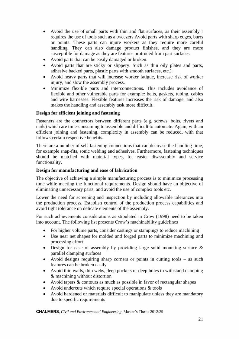
CHALMERS, Civil and Environmental Engineering, Master’s Thesis 2012:29
21
Avoid the use of small parts with thin and flat surfaces, as their assembly r
requires the use of tools such as a tweezers Avoid parts with sharp edges, burrs
or points. These parts can injure workers as they require more careful
handling. They can also damage product finishes, and they are more
susceptible for damage as they are features protruded from part surfaces.
Avoid parts that can be easily damaged or broken.
Avoid parts that are sticky or slippery. Such as thin oily plates and parts,
adhesive backed parts, plastic parts with smooth surfaces, etc.).
Avoid heavy parts that will increase worker fatigue, increase risk of worker
injury, and slow the assembly process.
Minimize flexible parts and interconnections. This includes avoidance of
flexible and other vulnerable parts for example: belts, gaskets, tubing, cables
and wire harnesses. Flexible features increases the risk of damage, and also
makes the handling and assembly task more difficult.
Design for efficient joining and fastening
Fasteners are the connectors between different parts (e.g. screws, bolts, rivets and
nails) which are time-consuming to assemble and difficult to automate. Again, with an
efficient joining and fastening, complexity in assembly can be reduced, with that
follows certain respective benefits.
There are a number of self-fastening connections that can decrease the handling time,
for example snap-fits, sonic welding and adhesives. Furthermore, fastening techniques
should be matched with material types, for easier disassembly and service
functionality.
Design for manufacturing and ease of fabrication
The objective of achieving a simple manufacturing process is to minimize processing
time while meeting the functional requirements. Design should have an objective of
eliminating unnecessary parts, and avoid the use of complex tools etc.
Lower the need for screening and inspection by including allowable tolerances into
the production process. Establish control of the production process capabilities and
avoid tight tolerance on delicate elements of the assembly.
For such achievements considerations as stipulated in Crow (1998) need to be taken
into account. The following list presents Crow’s machinability guidelines
For higher volume parts, consider castings or stampings to reduce machining
Use near net shapes for molded and forged parts to minimize machining and
processing effort
Design for ease of assembly by providing large solid mounting surface &
parallel clamping surfaces
Avoid designs requiring sharp corners or points in cutting tools – as such
features can be broken easily
Avoid thin walls, thin webs, deep pockets or deep holes to withstand clamping
& machining without distortion
Avoid tapers & contours as much as possible in favor of rectangular shapes
Avoid undercuts which require special operations & tools
Avoid hardened or materials difficult to manipulate unless they are mandatory
due to specific requirements

CHALMERS, Civil and Environmental Engineering, Master’s Thesis 2012:29 22
Design work pieces to use standard cutters, drill bit sizes or other tools
Avoid small holes as drill bit breakage gets greater
Design to avoid unneeded surface finish requirements
When tolerance is tight, production processes will be difficult and the connectivity
itself will be complex. During assembly, the tolerance problem can be solved by
introducing features that guide the insertion such as chamfered edges, external guides
and slots. In the absence of these guides higher tolerances make the assembly
processes more difficult and put a need to undertake on-site surface finishing
requirements.
2.5 DFMA: state of the art in the construction industry
It is beneficial to carefully study and identify factors and decisive criteria, as well as
design and assembly methods that have successfully been adopted from other
industries and applied in the construction sector. With a focus in the domain of
DFMA, this can be accomplished by conducting literature studies on the application
of DFMA in civil construction.
As mentioned earlier DFMA rules and principles are used by a wide range of
companies in different industries (Fox et al., 2002). Part of the research question in
this work is to what extent the principle can be applied in the construction industry in
a view to bring the said efficiency in saving time and money. Considering the
significant impact of design tasks on construction productivity and quality, it would
be of great potential for the construction industry to integrate the principles of DFMA
in its design phases where multiple decisions are passed (Fox et al., 2002).
For the reason that there are distinctive differences between the manufacturing and
construction industry, one cannot simply apply methods used in other industries into
construction without making some adoptions. However, there have been multiple
studies on different design methods which are being transferred to the construction
industry (Fox et al., 2002, Bibby, 2003). For example applying the lesser part thinking
of DFMA into bridge building would induce difficulties in terms of transportation and
handling, as parts of the product are scrutinized forging the part to a near-net shape
from the start (Dewhurst, 2010, Herrmann et al., 2004). In construction, there has to
be some kind of balance between bulky parts and assembly magnitude.
Concurrent Engineering has been an interest to the construction academia and
practitioners for few decades (Khalfan et al., 2000). In earlier sections it is noted that
DFMA tools are in place to integrate design and production considerations thereby
assuring the achievement of objectives of Concurrent Engineering. On the other hand
it is shown that design tasks are commonly performed by holding the design and
construction processes separated and following traditional/sequential design
approaches as reinforced by Fox et al., (2002) and an interviewee from Skanska.
Khalfan et al. (2000) shows results from few case studies that are conducted to study
the factors for readiness of applying Concurrent Engineering in the construction
industry. The article concludes that the most important ingredient which promotes
easy application is the people engaged in projects (e.g. teams in an organization),
while the technological wing is the not as equally important in the subject matter. This
leads to the need for continuous improvements in the management and governance
styles of human resource. The results also reveals that among different parties
engaged in construction projects sub-contractors show the most interest and readiness
for the implementation of Concurrent Engineering. While clients and consulting

CHALMERS, Civil and Environmental Engineering, Master’s Thesis 2012:29
23
organizations are observed to be moderate in the integration moves, suppliers and
manufacturers portray a significantly low readiness factor (Khalfan et al., 2000).
Another design method which is used for improvement of construction processes is
the implementation of constructability rules. By addressing production issues early in
the design phase, these constructability rules bring the said improvements in design
objectives from a production perspective (Fox et al., 2002). Constructability rules are
easy to formulate and/or obtain, and they are meant to be used as set of guidelines
compiled from some best practices in construction. A typical example of such a
design objective can be “design for minimum time below ground”. This design
objective is clearly devised to avoid difficult and dangerous work situations (Fox et
al., 2002). Some constructability rules are formulated in line with instinct of
construction workers, thus tasks are seen to be accomplished without a need to follow
lows and regulations. Such a thing can be for example, the use of concrete blocks
instead of clay bricks. Due to their well-defined shape and form and also the
possibility in their material type to manufacture bigger parts with reduced numbers, it
is evident that concrete blocks are preferred to clay bricks as it is difficult to align
them incorrectly during actual assembly.
Traditionally, the absence of constructability rules in design is blamed on the
architects, that their lack of construction knowledge is the cause for problems in
productivity and quality (Fox et al., 2002). According to Fox et al. (2002) even if
there are quite a few successful computerized applications for design, they have only
been linked separately to different stages of designs, not in a procedure which
supports the concept of DFMA. On the other hand technology has advanced in the
modeling aspect. 3D work and prototyping of designs are technically more feasible
(Fox et al., 2002). These tools are developed further with fourth or fifth dimension,
for example inclusion of time dimension in construction planning, making them
useful tools for design methods to be applied better. Furthermore, it was concluded
that actions can be taken to develop the constructability rules on a wider aspect and
increase their success (Fox et al., 2002).
Constructability rules – field study
Using DFMA rules Fox, et al. (2002) performed a field study to investigate how rules
applied could improve design to further create construction productivity and quality
benefits. The study was tested on the design of assisted bathrooms contained within
the bedrooms of a healthcare facility. The DFMA rules used were:
Field study Rule 1: Ensure adequate access and unrestricted vision
Field study Rule 2: Design parts that cannot be installed incorrectly
The DFMA rules were applied (see Table 2-1 & 2-2) and with an adoption of rule 2
into construction, a new constructability rule could be compiled (see Table 2-3). By
discussing these rules with workers, questions could be formulated. Using these
questions in a work breakdown process the two rules could be fulfilled in a successful
way, which led to design improvements. As a result, reduced production time and cost
were achieved. For example, the design improvements on the WC panels saved one
man-week of work for the plumbing contractor. Another example is the reduction by
20% on the rework costs to wall vinyl welds and wall penetrations as estimated by the
relevant specialist workers (Fox et al., 2002).

CHALMERS, Civil and Environmental Engineering, Master’s Thesis 2012:29 24
Table 2-1 Design improvements (source: Fox, 2002)
Rule applied Detail Design improvement Rule 1: Ensure
adequate access and
unrestricted vision
WC panels
Wall vinyl
Framing section reduced
Weld moved from
corner
Rule 2: Design
subassemblies that
cannot be constructed
incorrectly
Floor screed
Wall penetrations
Specific batch recipe
defined
Use of neoprene gaskets
Table 2-2 Construction productivity and quality benefits (source: Fox, 2002)
Rule applied Detail Benefits Rule 1: Ensure
adequate access and
unrestricted vision
WC access panels
Wall vinyl
Reduced production
time and cost
Reduced rework cost
Rule 2: Design
subassemblies that
cannot be constructed
incorrectly
Floor screed
Wall penetrations
Reduced production
time and cost
Reduced rework cost
Table 2-3 Sample new constructability rule (source: Fox, 2002)
Design rule Design strategies Minimize cutting by:
*Matching sizes of bespoke components with standard
material sizes
*Harmonizing the building’s structural, envelope
and internal grids
*Positioning internal fittings within the building’s
partitioning grids
These constructability rules can be seen as an obvious procedure in construction. Yet,
there is capacity to further develop the idea of using DFMA as design procedures or to
compile constructability rules. Constructability rules have been available for a number
of years, but compared to other industries, there have not been advancements in the
construction industry to fully develop these rules into a framework (Fox et al., 2002).
It is known that global competition, producer-led market specific design, and
concurrent engineering are more prevalent in other industries (Boothroyd, 1994,
Giudice et al., 2009).
However, one field study is not enough to make a general conclusion on the
effectiveness of applying DFMA on constructability rules. By addressing the
development of constructability rules, discussion can start and further improvements

CHALMERS, Civil and Environmental Engineering, Master’s Thesis 2012:29
25
can be generated. For this, there is a need of pressure from e.g. clients. (Fox et al.,
2002) also present guidelines for application of rules in a successful way:
Guidelines for successful application
1. Focus rules on each design stage in sequence – Which rules to use and in what
sequence, during each design stage. Using DFMA, construction books, and
production management knowledge to provide rules that will have an overall
improvement on productivity and quality of the whole construction.
2. Support rules with self-explanatory strategies and production database –
Provide guidance for designers, formulated by component designers with the
revision of the construction manager and building designer. Especially in
traditional procurement methods, rules should be integrated with production
databases.
3. Develop routine and foolproof application methods for rule – Start with
traditional manual, workbooks to develop knowledge-based engineering
(KBE) software. These tools can have different factors built into it, for
example production feasibility and safety risks.
4. Target rules on best available productivity/quality improvement opportunities
– Formulate rules that fit the organization’s opportunities without
compromising the constructability of each building as a whole. Consideration
needs to be taken between bespoke component and standard component, to
design for manufacture and/or to simplify assembly.
There are several examples of bridge constructions that have gone through
improvements in their design objectives. Some of the current advanced design tasks
consider similar principles that are underpinned by DFMA systems. The design of
integral abutment and jointless bridges is such an example, which envisages
construction/ production costs and maintenance issues which are important part of
sustainability (Mistry, 2000)
An integral abutment bridges are designed without expansion joints in the bridge
decks, where thermal and braking loads on the superstructure are absorbed through
the superstructure and abutments into the soil. In order to not overloading the
abutment, the piles have to follow the bridge’s deformation. Therefore only one row
of flexible piles is used in each abutment. The downside of these bridges is that there
is a limitation to the deformation of the bridge due to the method. Therefore, it is
sensitive to temperature differences and the limitation of the span is depended on the
geographical climate (Mistry, 2000). However the main benefits gained from the
concept is a simple design that allows a faster construction, since fewer parts and piles
are needed and back wall can be cast simultaneously. When replacing or constructing
integral abutment bridge, it can be built around existing foundations without requiring
complete removal of existing substructure (Mistry, 2000).
No joints and bearing are needed, which are expensive to buy, install, maintain and
repair and even more costly to replace. Consequently one of the most frequent
corrosion problems will not be prevalent anymore. This is due to leaking of expansion
joints, allowing surface water with salt from the roadway to attack girder ends,
bearings and supporting reinforced concrete substructures. With a smooth jointless

CHALMERS, Civil and Environmental Engineering, Master’s Thesis 2012:29 26
construction, vehicular riding quality will be improved and diminishes vehicular
impact stress levels. All these advantages lead to less construction and maintenance
cost, furthermore less time spent on-site with production and higher quality is
achieved (Mistry, 2000).

CHALMERS, Civil and Environmental Engineering, Master’s Thesis 2012:29
27
3 DFMA Criteria and PANTURA Indicators
Part of the task in this thesis work is to evaluate the assembly methods for their
suitability in meeting the PANTURA indicators. This requires identification of a
number of bottlenecks and vital criteria that are prevalent during the installation of
bridges. These criteria will then be interpreted into the PANTURA indicators and will
be used as process parameters that must be fulfilled for the bridge installation to be
fast and efficient. This chapter will undergo through parameters that need to be
considered when implementing DFMA in bridge construction. These parameters are
drawn mainly from literature studies and developed by interviews that are conducted
in a view to strengthen the knowledge and adapt the DFMA criteria for their use in the
construction of bridges.
3.1 PANTURA indicators in bridge construction
Even though the workplace, composition of personnel and project context are set
beforehand, construction projects are yet unique by nature (Larsson and Emborg,
2011), as the activities are dynamic and full of contingencies. Despite their
uniqueness, certain general and common criteria can still be identified among
different construction projects. These general criteria, therefore, can be taken into
consideration and be applied regardless of the differences in projects and work
settings. Such general/common criteria in bridge construction are set forward by
project PANTURA. The PANTURA indicators presented in this section are demands
put on the construction of bridges in a view to meet social, environmental and
sustainability issues. The list of PANTURA indicators are:
1. Mobility
2. Lifecycle Cost
3. Time
4. Worker Safety
5. Safety of Residents
6. Noise Disturbance
7. Dust Emissions
8. Greenhouse Gas Emissions
9. Energy Use
10. Waste Reduction and Recycling
The indicators listed above are the basis for the evaluation method established in this
thesis work, as the assessed assembly techniques and technical concepts will be
evaluated for their performance in meeting the individual PANTURA indicators.
3.2 DFMA translation of PANTURA indicators
The DFMA criteria presented in Section 2.4 are general attributes that are considered
during the implementation of DFMA principles in product developments. The
translation of PANTURA indicators into DFMA criteria is accomplished by
identifying measurable traits in each general criterion and assigning them to the
PANTURA requirements. In order to facilitate easy tracking of desirable traits during
product designs, the general DFMA criteria were carefully disintegrated and
characterized according to measurable traits of DFM and DFA. As a result, the
DFMA translation is completed by assigning DFM and DFA traits to each one of the
PANTURA indicators.

CHALMERS, Civil and Environmental Engineering, Master’s Thesis 2012:29 28
3.2.1 Characterization of the general DFMA criteria
Multi directional visualization of the impact of each of the aforementioned general
DFMA criteria is a key to realize how they directly or indirectly affect achievement of
the PANTURA goals in relation to bridge construction. Proper understanding of the
influence they impose enables reasonable allocation of weights before the actual
evaluation of assembly techniques and technical concepts, which will be dealt in
Chapter 5.
For the sake of convenient tracing of DFMA criteria back in the product design, the
guidelines are categorized in accordance with their manufacturing and assembly
characteristics, and are analyzed in their respective category. In the forthcoming
section, it is important to note the dual properties of some of the DFMA criteria as
they possess both manufacturing and assembly characteristics and potentially
influence both blocks of a new product development.
The two subsequent tables will present a summary of the important DFMA criteria
discussed in Section 2.4. Some exclusive manufacturing and assembly features of
each criterion alongside with their respective desired and undesired attributes are
pointed out and shown for further ease during assigning weights to each characteristic
and scoring the assembly techniques. There can be enormous characteristics attributed
to each general criterion but, here, only the characteristics that have a perceived direct
relation with and effect on assembly process are considered.
Table 3-1 General DFMA criteria, their manufacturing characteristics and traits
General DFMA
Criteria
Manufacturing
Characteristics
Desired Traits Undesired
Traits
Simplified design
for manufacturing
*Fabrication steps
*Performance of
Parts
*Compatibility of
processes with
materials and
production volumes
Few
Qualified
Compatible
Many
Defective
Incompatible
Reduced number of
parts
*Combining parts
(mould one piece
rather than two
pieces)
Combined Disintegrated
Standardize and use
common parts and
materials
*Material types
used in producing
the parts
*Need for
additional
Experiment
Desired
No
Undesired
Yes

CHALMERS, Civil and Environmental Engineering, Master’s Thesis 2012:29
29
General DFMA
Criteria
Manufacturing
Characteristics
Desired Traits Undesired
Traits
Mistake-proof
product design
*Physiology of
components (Leads
to number of
possible ways of
Assembly)
*Design of notches,
asymmetrical holes,
external guides and
stops
*Design of parts
which incorporates
symmetry around
both axes of
insertion
Only one
Present
Yes
More than
one
Absent
No
Design for ease of
parts orientation,
handling and
assembly
*Property of
surfaces and sizes
of parts, so that
they can easily be
placed and
assembled
*Parts that are
sticky, slippery and
with sharp edges,
burrs, and points
*Parts weight
Graspable
Absent
Light
Ungraspable
Present
Heavy
Design for efficient
joining and
fastening
*Match fastening
techniques with
materials
Yes No
Design to avoid
unneeded surface
finish requirements
*Tolerances High Low
In a similar fashion as for the table above, distinctive assembly features of each
general DFMA criterion are traced and listed alongside with respective desired and
undesired traits for further ease in a segmental analysis and assigning of weights for
each of the characteristics and scores during evaluation.

CHALMERS, Civil and Environmental Engineering, Master’s Thesis 2012:29 30
Table 3-2 General DFMA criteria, their assembly characteristics and traits
General DFMA
Criteria
Assembly
Characteristics
Desired
Traits
Undesired
Traits
Simplified design
for assembly
*Assembly error
*Assembly ease
*Disassembly ease
*Need for more
complex tooling due
to unnecessary part
features
Few
Easy
Easy
No
Many
Difficult
Difficult
Yes
Reduced number of
parts
*Assembly steps
*Number of
fasteners in use
Few
Few
Many
Many
Standardize and use
common parts and
materials
*Handling and
assembly
operations
*Operator learning
Standardized
Simplified
Unstandardized
Complicated
Mistake-proof
product assembly
*Assembly process Unambiguous Ambiguous
Ease of parts
orientation,
handling and
assembly
*Assembly direction
*Flexible and flimsy
parts such as belts,
gaskets, cables, and
wire harnesses
Unidirectional
Absent
Multidirectional
Present
Efficient joining
and fastening
*Use of threaded
fasteners (screws,
bolts, nuts and
washers)
No Yes
Unneeded surface
finish requirements
during assembly
*Guided insertion
(for example:
presence of
chamfered edges)
Yes No
3.2.2 Translation of the PANTURA indicators
In order to facilitate evaluation of the techniques with respect to PANTURA
indicators, each DFMA criteria along with their respective manufacturing and
assembly characteristics are considered in conjunction with their perceived impact on
the different indicators separately.

CHALMERS, Civil and Environmental Engineering, Master’s Thesis 2012:29
31
Description of the demands put on the construction of bridges (PANTURA indicators
listed in Section 3.1) as described in Thodesen et al. (2011) is presented hereafter.
Translation of the indicators into DFMA requirements has also been done alongside in
order to assign DFMA behaviour for the respective indicators. The DFMA behaviours
assigned to each PANTURA indicators are selections from the manufacturing and
assembly characteristics of the general DFMA criteria presented in Tables 3.1 and 3.2.
The translation has been done by describing each PANTURA indicators in terms of
significant DFMA considerations and criteria in bridge construction.
a. Mobility
General Description: Mobility is expressed as the time elapsed during the
transportation of a vehicle from one point to another on a given transport route. It is
considered as highly important factor, especially in the construction planning of
infrastructures such as roads and bridges, the closing of which highly impedes
mobility of traffic. As already mentioned, during analysing this indicator,
considerations need to be taken to civil engineering works influencing the
transportation facility and cause pedestrian and/or vehicle lane closures (Thodesen et
al., 2011). When there is less or no need for stacking a construction material on-site,
there will be significant reduction in the probability of lane closures and mobility
disruptions due to traffic bottlenecks created by the stored materials. Another aspect
can be the need for frequent maintenance due to unwanted weak joints in the final
product. Whenever there is the need for maintenance, there will also be a need to
close the traffic to facilitate the maintenance work. The deployment of workers and
machinery which occupies a great deal of space during construction activities makes
mobility disturbance a point of interest in urban development.
Translation: The general DFMA criteria that are closely linked to mobility are:
Reduced number of parts
Mistake-proof product design
Design for ease of parts orientation, handling and assembly
Simplified design for assembly
Standardize and use common parts and materials
Ease of parts orientation, handling and assembly
Efficient joining and fastening and
Unneeded surface finish requirements
Unlike the above two PANTURA indicators, the DFMA characteristics used in the
characterization of traffic mobility requirements are both manufacturing and assembly
related as described below:
Property of surfaces and sizes of parts, so that they can easily be placed and
assembled: Simple handling can be sufficient with graspable assembly parts, while
ungraspable assembly elements may require deployment of more machineries and
human work which makes use of wider urban space during construction.
Parts weight: Heavy machinery is needed for the handling, storage and assembly of
heavy assembly parts. If the construction planning does not take these factors into
consideration, the involvement of heavy machineries during loading and unloading
puts a need for extra space. This as a result creates bottlenecks in a given traffic
movement.

CHALMERS, Civil and Environmental Engineering, Master’s Thesis 2012:29 32
Assembly error: Depending on the time of realization of the assembly error,
rectification works can be considered as maintenance activities. During rectification
of assembly errors during service life, there may be a need to close lanes and interrupt
the traffic.
Need for more complex tooling due to unnecessary part features: Careful handling
and storage is required in order not to damage assembly parts with delicate features.
In such circumstances, more number of machineries and construction workers come
in play thereby seizing the traffic flow.
Assembly steps: The steps that need to be followed in order to complete an assembly
cycle are also decisive factors in mobility. As the number of assembly steps increases,
varied assembly parts need to be transported segmentally and different construction
machineries may need to be employed for the handling of the varied parts in each
assembly step. This is a potential cause for frequent lane closures due to temporary
storage at work spots.
Number of fasteners in use: The direct relation between numbers of fasteners used
during assembly steps and the number of assembly parts is a point of interest here.
Increased numbers of fasteners imply the presence of large number of parts in an
assembly. The need to accommodate these assembly parts in a confined area of
storage can be a challenge without prior planning or lane closures.
The number of joints in an assembly can also increase with the number of fasteners
used. These joints created by the fasteners create weak shear surfaces in the final
product. Whenever a need arises for maintaining these weak zones, there is also a
need to close lanes and temporarily interrupt traffic to facilitate the work.
Handling and assembly operations: Workers operating under unstandardized systems
are likely to use excessive resources including machineries and construction materials.
Due to the prevailing erratic nature of the construction activity, construction materials
including assembly parts can be stored in different places thereby utilizing extra space
which, otherwise, would have been used for accommodating diverted traffic etc.
Assembly process: The presence of non-value adding activities due to ambiguous
assembly operations will cause unwanted movements of construction machinery and
workers. This creates a situation where wide area of construction space being used
unnecessarily, there by closing lanes and parking spots in the vicinity.
Assembly direction: When designing processes of assembly, enough attention should
be given as to avoid multidirectional assembly requirements. When an assembly
needs to be done from multiple directions, depending on the circumstances of the area
in proximity, there is an associated need for traffic lane closure. Assembly direction
needs to be adapted to circumstances of the construction site to avoid interference
with existing traffic.
b. Lifecycle cost
General Description: It is a challenge to assess life cycle costs (LCC) since it
requires prediction of fluctuating future and calculation of net present values.
Nonetheless, calculation of LCC is an important part of considering the long-term
issues and assuring sustainable development. Currently there are established methods
and tools used for calculating LCC for civil engineering works so that comparison
among different construction alternatives can be made (Thodesen et al., 2011).

CHALMERS, Civil and Environmental Engineering, Master’s Thesis 2012:29
33
When introducing new working methodologies into a system, the methods have to be
evaluated for their performance in terms of the overall lifecycle cost. LCC includes all
the cost associated with and incurred during the design life of a certain civil
engineering work. Construction costs, social costs, operation costs, waste disposal
costs etc. are integral parts of the LCC.
Construction and maintenance costs are the main pillars in the evaluation of the total
lifecycle cost. Usually when there is a need to make a comparison between different
construction solutions, similar work settings will be assumed and estimation of
construction cost will be performed by a mere calculation of the required amount of
construction material (e.g. concrete, piles, and reinforcement). The main factors
accounting for approximately 50% (excluding foundation) of the total construction
cost, in concrete structures, are reinforcement, formwork and in-situ casting
(Simonsson and Emborg, 2007). Precisely, construction cost is mainly determined by
the extent of work set on-site and the amount which is produced. As less time spent
on-site with machines and workers, there will be a great deal of construction cost
savings (Simonsson and Emborg, 2007, Rwamamara, 2010).
Maintenance costs need to be converted to net present values with an agreed internal
rate of return for the design life of the civil structure. Maintenance costs have an
indirect relation with quality of the final product. There is no common use of
industrialized methods in different work settings; therefore the said quality can vary in
different markets. For example products with different qualities can be obtained from
using prefabricated elements or reinforcement bars (Simonsson and Emborg, 2007,
Eriksson and Jakobson, 2009). Typically, products (specifically bridges) assembled
from prefab elements have a weak failure zone, as connection surfaces or joints are
created during assembly. Bridge elements (e.g. joints) are subjected to fatigue due to
repeated impact loading from vehicular live loads, and expansion/contraction
movements due to weather changes. These factors coupled with depreciation and
corrosion problems increase the need for maintenance (Mistry, 2000).
Translation: The general DFMA criteria that are closely linked to lifecycle cost are:
Simplified design for manufacturing
Standardize and use common parts and materials
Design for efficient joining and fastening
Design to avoid unneeded surface finish requirements
Simplified design for assembly
Reduced number of parts
Ease of parts orientation, handling and assembly
Efficient joining and fastening
Unneeded surface finish requirements
Both manufacturing and assembly characteristics have a tread on these general DFMA
behaviours of lifecycle cost. The explanation of each characteristic is presented
below:
Fabrication steps: As the lead time of the product increases with greater number of
fabrication steps, part of lifecycle costs, such as direct construction/fabrication costs
can be affected by the number of steps involved in a fabrication process.
Performance of Parts: Performance of parts is manifested by a defective or qualified
final product. Defective product requires rectification and/or maintenance thereby
affecting the lifecycle cost. Parts with the required quality yield a qualified final

CHALMERS, Civil and Environmental Engineering, Master’s Thesis 2012:29 34
product which does not require frequent maintenance in its service life. In the case
where individual assembly parts do not have the intended quality, the design life of
the bridge could face significant reduction as integrity among the bridge parts is in
question. There has to be a trade-off between the initial higher costs incurred during
the extraction process and the longer life of the final product produced from costly
materials. For example even if higher cost is incurred during extraction and moulding
of steel, the material can be used with less requirement of maintenance during its
lifecycle and it can even be recycled.
Compatibility of processes with materials and production volumes: The compatibility
of materials used in the process of fabrication and the processes followed has also an
impact on lifecycle cost. For example some materials used in manufacturing steps
require only simple processing with simple machineries or even hand tooling. But if
the actual manufacturing process uses big machineries for the execution of such
simple tasks, the lifecycle cost will increase.
Material types used in producing the parts: This manufacturing characteristic also has
a direct influence over lifecycle cost. Parts can either be manufactured from cheaper
materials that are easy to extract, process and shape or materials that need expensive
extraction, purification and moulding works.
Need for additional Experiment: When there is a need to undertake additional
experiment for testing performance of produced parts, there will definitely be
respective additional cost associated with it.
Match fastening techniques with materials: When fastening techniques are adopted in
line with the type of material used for manufacturing the parts, the outcome of the
assembly process will have a better monolithic nature. When a different type of
material is used for fastening than the parent material, there will be a risk of quick
failure and thus maintenance and re-work.
Tolerances: When a bridge assembly part do not have the required absolute fit due to
tolerance issues, the entire structural system will be susceptible to frequent
maintenance arose from quality deterioration.
Assembly error: Assembly errors trigger need for maintenance and rectification works
thereby adding up lifecycle costs of the civil work.
Assembly ease: The easier the assembly process, the less the procedure requires
involvement of expertise and extra intensive tooling. This lowers the cost incurred for
involving professional personnel as existing workers can handle the operation with
minimal training.
Disassembly ease: The easier the disassembly process gets, the more it becomes
simple to operate. Easy and simple disassembly steps do not require involvement of
extra machinery and heavy demolition. As a consequence workers can handle the
operation with minimal dismantling effort which does not cause extra cost incurred
for associated works.
Need for more complex tooling due to unnecessary part features: When extra care is
needed in a view not to damage fragile and/or unnecessary part features, more
complex tooling and delicate handling will be required. During this excessive
complex tooling works, extra machineries and additional workers come in place and
direct construction work will increase accordingly. Similarly if these unnecessary part
features are subjected to damage they may also require extra replacement costs.
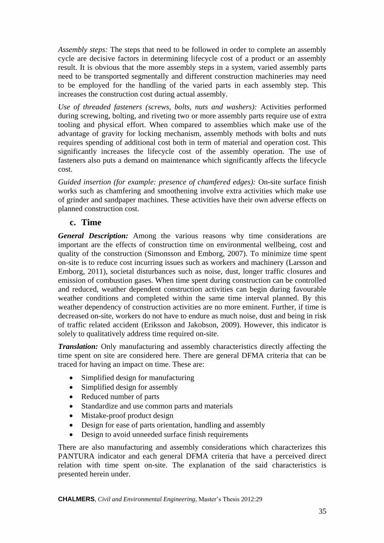
CHALMERS, Civil and Environmental Engineering, Master’s Thesis 2012:29
35
Assembly steps: The steps that need to be followed in order to complete an assembly
cycle are decisive factors in determining lifecycle cost of a product or an assembly
result. It is obvious that the more assembly steps in a system, varied assembly parts
need to be transported segmentally and different construction machineries may need
to be employed for the handling of the varied parts in each assembly step. This
increases the construction cost during actual assembly.
Use of threaded fasteners (screws, bolts, nuts and washers): Activities performed
during screwing, bolting, and riveting two or more assembly parts require use of extra
tooling and physical effort. When compared to assemblies which make use of the
advantage of gravity for locking mechanism, assembly methods with bolts and nuts
requires spending of additional cost both in term of material and operation cost. This
significantly increases the lifecycle cost of the assembly operation. The use of
fasteners also puts a demand on maintenance which significantly affects the lifecycle
cost.
Guided insertion (for example: presence of chamfered edges): On-site surface finish
works such as chamfering and smoothening involve extra activities which make use
of grinder and sandpaper machines. These activities have their own adverse effects on
planned construction cost.
c. Time
General Description: Among the various reasons why time considerations are
important are the effects of construction time on environmental wellbeing, cost and
quality of the construction (Simonsson and Emborg, 2007). To minimize time spent
on-site is to reduce cost incurring issues such as workers and machinery (Larsson and
Emborg, 2011), societal disturbances such as noise, dust, longer traffic closures and
emission of combustion gases. When time spent during construction can be controlled
and reduced, weather dependent construction activities can begin during favourable
weather conditions and completed within the same time interval planned. By this
weather dependency of construction activities are no more eminent. Further, if time is
decreased on-site, workers do not have to endure as much noise, dust and being in risk
of traffic related accident (Eriksson and Jakobson, 2009). However, this indicator is
solely to qualitatively address time required on-site.
Translation: Only manufacturing and assembly characteristics directly affecting the
time spent on site are considered here. There are general DFMA criteria that can be
traced for having an impact on time. These are:
Simplified design for manufacturing
Simplified design for assembly
Reduced number of parts
Standardize and use common parts and materials
Mistake-proof product design
Design for ease of parts orientation, handling and assembly
Design to avoid unneeded surface finish requirements
There are also manufacturing and assembly considerations which characterizes this
PANTURA indicator and each general DFMA criteria that have a perceived direct
relation with time spent on-site. The explanation of the said characteristics is
presented herein under.

CHALMERS, Civil and Environmental Engineering, Master’s Thesis 2012:29 36
Combining parts (mould one piece rather than two pieces): When bigger assembly
parts are manufactured by combining smaller ones, there will consequentially be
shorter time spent on site due to the less number of parts to deal with.
Physiology of components: This manufacturing trait is perceived to have a significant
impact on worker safety. Physiology of components is an expression used for the
physical feature of parts that result in a number of possible ways of assembly. Some
parts can be manufactured in such a way that their physical feature allows different
ways of assembly while there is only one single correct way of assembling them. A
typical simple example of this can be, plugging yellow and red jacks into their
respective slots while setting up a sound system. Had it been the jacks were not
distinguished with different colourings, there would have been a possibility to
wrongly plug them into the wrong slots. Even though, wrong plugging is not
physically restricted, the sound system will not give the intended result unless one
assembles them in the only one right way. Inherent mistake proofing can be attributed
to an assembly system, by manufacturing assembly parts in such a way that there is
only one possible and correct assembly alterative. Assembly mistakes during setting
up a sound system can only be recognized when the assembly outcome fails to serve
the intended purpose (i.e. not giving a sound). There are no differentiations in part
features and/or physical restrictions in the jacks to avoid assembly mistakes. Thus
identification of errors during the assembly process and swift addressing of mistakes
is not possible. In a bigger perspective, such as bridge assembly, once the entire
assembly procedure is completed it is difficult to address mistakes committed in
earlier steps, and a trial to do so consumes great deal of time.
Design of notches, asymmetrical holes, external guides and stops: the incorporation of
notches, additional holes, guides and stops greatly helps in minimizing assembly
errors and thus rework needs which affects time.
Design of parts which incorporates symmetry around both axes of insertion: Mistake
proofing in assembly processes can also be achieved by allowing multiple axes of
insertion. When parts have a symmetrical feature in both axes of insertion, the
assembly process will have an inherent mistake proofing attribute, as there is no
mistake committed in assembling the part in either axes. In such a case less time will
be spent in a trial to figure out correct orientation of the parts during assembly
operations. The difference in this characteristic from Physiology of components is that
parts can be assembled correctly in all possible alternatives.
Property of surfaces and sizes of parts, so that they can easily be placed and
assembled: When parts are designed and manufactured in such a way that they have
physical features such as a handhold or impressions for firm holding and hanging
during assembly, they are said to be easy to grasp, thereby reducing time spent in firm
tying. Relatively, graspable parts do not require a great deal of time to handle and
operate than ungraspable ones.
Parts that are sticky, slippery and with sharp edges, burrs, and points: Due to such
features of assembly parts as sticky and slippery surfaces and sharp edges, parts
handling and operation can be a challenge. Activities of logistics, stacking, and
assembly of parts can be more efficient and fast if there are not plenty of
considerations needed in order not to damage parts due to their undesired surface
features.

CHALMERS, Civil and Environmental Engineering, Master’s Thesis 2012:29
37
Parts weight: Handling heavy parts at a work site requires intensive physical work
and heavy construction machinery usage. Light assembly parts require light
machineries and are easy for faster handling on site.
Tolerances: When parts are manufactured in such a way that they inherit
exaggeratedly higher tolerances, they will cause a need for on-site preparations and
surface finish works that have their own respective time consumption.
Assembly error: As it was explained earlier, depending on where in the assembly
process mistakes are noted, errors during assembly cause needs for rectification and
re-work. As the number of errors during construction increase, there will be a greater
chance for frequent rectification work needs, which slips the time to complete the
construction project.
Assembly ease: The easier the assembly process is, the more the process becomes
easy to internalize. Easy and simple assembly steps do not require involvement of
expertise and workers can handle the operation with minimal adaptation time. When
the assembly has easy guides and procedures to follow, then it is simpler to train
workers about the specifics of the assembly in question. Assembly processes with
easy guidelines and procedures have an inherent time saving attribute by avoiding
risks of re-work needs linked to errors and faulty assemblies.
Disassembly ease: The easier the disassembly process gets, the more the process
becomes easy to handle. Easy and simple disassembly steps do not require
involvement of extra machinery and heavy demolition and workers can handle the
operation with minimal time and effort during dismantling.
Assembly steps: The number of steps that need to be followed during assembly
operations significantly determines the time required to complete an assembly cycle.
In another sense, workers when shifting from one assembly task to the other, they are
also likely to take an interval of time before they adapt the new assembly task. As a
result, there is certain time wasted during the onset of initial tasks in each assembly
step.
Number of fasteners in use: It is not difficult to see the extra work required when
there is a need of using excessive fasteners and connectors during assembly.
Depending on how the fasteners are designed to be used or provided being welded
with assembly parts, numbers of fasteners used for assembly can be a time demanding
issue.
Handling and assembly operations: When handling and assembly operations are
considered, standardization of the process is at the heart. When an assembly process is
standardized, the tasks can be accomplished at a relatively faster rate. Due to the
routines, workers will also have a greater chance to internalize the tasks involved,
thereby avoiding extra time spent in non-value adding activities due to unstandardized
systems.
Assembly process: Ambiguous assembly operations make work areas unclean and
erratic. As site workers do not have the clear picture of the tasks involved, there will
consequently be increased rate of occurrence of trials and errors in an effort to figure
out the correct assembly way. Assembly operations should be unambiguous for the
system to save time invested in all these ambiguous tasks.
Assembly direction: When designing processes of assembly, enough attention should
be given as to avoid multidirectional assembly requirements. When an assembly

CHALMERS, Civil and Environmental Engineering, Master’s Thesis 2012:29 38
needs to be done from multiple directions, there is associated workers’ and machinery
movement from one side to another. This as a result causes an investment in extra
time.
Guided insertion (for example: presence of chamfered edges): High tolerances in
assembly parts causes on-site adjustment demands (e.g. surface finishing works) for a
firm fit. During times when assembly parts does not fit to each other, for example due
to sharp corners and dimensional alterations, on-site surface finish requirements may
be required to allow the intended fit. On-site surface finish works involve activities
such as cutting and smoothening, which make use of part of a construction which
would have been used for more value adding activities.
d. Worker safety during construction
General Description: Design for ease of handling and manipulation leads to increased
safety at a work site. The working environment on-site is more physically demanding
than what is there in pre-conditioned in-door environment. There are several factors
that subject workers to a risk of injury and danger. Conditions of the site including
weather and traffic, machineries, noxious fumes or chemicals, working platforms such
as scaffolding and placement of formworks, elements or materials that require
complex handling and time pressure are some of the many. Dealing with some of
these factors require inappropriate working positions and heavy lifts thus resulting in
falling accidents, injuries and chronic pains, as the most common type of injury at
work are strains and sprains (Rwamamara, 2010).
Worker safety on-site can be achieved, for example, by introducing advanced
construction techniques that require less on-site preparation such as excavation and
machinery usage; since these in turn reduce the human work required to handle the
work. In case of some construction methodologies such as prefab, as structural
elements can be casted off-site in a conditioned in-door manufacturing environment,
risk of accidents associated with on-site operation can be significantly reduced.
However, there is also a trade-off between the dangers caused during handling of
readymade bulky structural elements and injuries associated with minor detailing
works on-site, such as reinforcement placing and fastening.
Translation: The translation of this PANTURA indicator can be expressed in terms
of few relevant manufacturing and assembly characteristics from a DFMA
perspective. There are general DFMA criteria that can be traced for having an impact
on worker safety. These are:
Mistake-proof product design
Design for ease of parts orientation, handling and assembly
Design for efficient joining and fastening and
Design to avoid unneeded surface finish requirements
There are also manufacturing characteristics under each general DFMA criteria that
have a perceived direct relation with worker safety on-site. The explanation of each
manufacturing characteristics is presented herein under.
Physiology of components: This can be made clear by using the earlier example which
explains the setting up of a sound system with coloured cables and jacks. If there are
number of possible ways of assembling the same part, workers are susceptible for
making mistakes and cause needs of frequent rework. Mistakes are primary causative
agents for hazards by making the assembly process susceptible for accidents. When

CHALMERS, Civil and Environmental Engineering, Master’s Thesis 2012:29
39
frequent rework needs arise workers may also get exhausted due to mental fatigue
making them commit more errors.
Design of notches, asymmetrical holes, external guides and stops: These
manufacturing traits of a product prevents errors during assembly by guiding the
assembly, allowing multiple correct assembly orientations, and producing a clicking
sound when the part locks into its right fit. When assembling such parts mistakes will
be avoided to a greater extent thereby reducing adverse effects associated with them.
Design of parts which incorporates symmetry around both axes of insertion: When
parts have a symmetrical feature in both axes of insertion, the assembly process will
have an inherent mistake proofing attribute, as there is no mistake committed in
assembling the part in either axes. In such a case less human work and physically
intensive work will be required as there is no need to re-orient the part during
assembly operations.
Property of surfaces and sizes of parts, so that they can easily be placed and
assembled: When parts are designed and manufactured in such a way that they have
physical features such as a handhold or impressions for firm holding and hanging
during assembly, they are said to be easy to grasp, thereby reducing accidents due to
difficulties in handling and operation.
Parts that are sticky, slippery and with sharp edges, burrs, and points: Due to such
features of assembly parts as sticky and slippery surfaces and sharp edges, parts
handling and operation can be a challenge. Working in such a challenging condition
will result in increased probability of hazard occurrence. Presence of sticky or smooth
surface properties of assembly parts are undesired traits. With the presence of
slippery surfaces, for example, there is a danger of parts escaping from the harness
which keep them hanged on a crane or parts with sharp edges cause dangers to works
as they require delicate handling.
Parts weight: Handling heavy parts at a work site requires intensive physical work
and construction machinery usage. The more effort it takes to carry or handle the
assembly parts, the greater the probability that muscle fatigue, strains or sprains will
occur and endanger the worker safety.
Match fastening techniques with materials: The fastening techniques used during
assembly need to facilitate easy lock and key fittings of the assembly parts without a
need to engage extra man power. The need for an extra tool or work for fastening and
worker to guide the joining may put worker safety in question.
Tolerances: Tolerance, in this thesis work context, can be expressed as the maximum
permissible deviation in measurement that a product can have in relation to the
required absolute fit. When parts are manufactured in such a way that they inherit
exaggeratedly tight tolerances that are beyond the natural capability of the material
they are made of, they will cause unneeded on-site preparations and surface finish
works that results in increased treat for worker safety.
Few assembly characteristics that have a perceived direct relation with worker safety
on-site are:
Assembly error: As it was explained earlier, errors during assembly are sources of
problems in worker safety during construction. As the number of errors during
construction increase, there will be a greater chance for injuries and hazards to occur
due to unplanned rectification works.
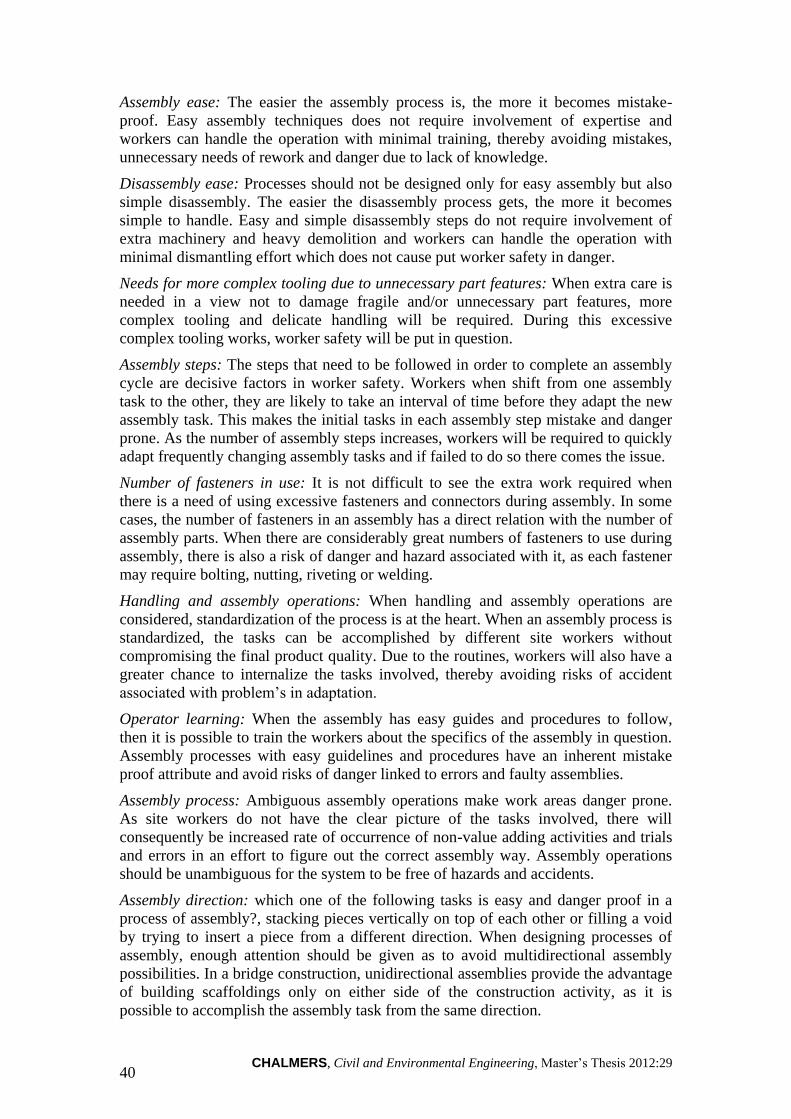
CHALMERS, Civil and Environmental Engineering, Master’s Thesis 2012:29 40
Assembly ease: The easier the assembly process is, the more it becomes mistake-
proof. Easy assembly techniques does not require involvement of expertise and
workers can handle the operation with minimal training, thereby avoiding mistakes,
unnecessary needs of rework and danger due to lack of knowledge.
Disassembly ease: Processes should not be designed only for easy assembly but also
simple disassembly. The easier the disassembly process gets, the more it becomes
simple to handle. Easy and simple disassembly steps do not require involvement of
extra machinery and heavy demolition and workers can handle the operation with
minimal dismantling effort which does not cause put worker safety in danger.
Needs for more complex tooling due to unnecessary part features: When extra care is
needed in a view not to damage fragile and/or unnecessary part features, more
complex tooling and delicate handling will be required. During this excessive
complex tooling works, worker safety will be put in question.
Assembly steps: The steps that need to be followed in order to complete an assembly
cycle are decisive factors in worker safety. Workers when shift from one assembly
task to the other, they are likely to take an interval of time before they adapt the new
assembly task. This makes the initial tasks in each assembly step mistake and danger
prone. As the number of assembly steps increases, workers will be required to quickly
adapt frequently changing assembly tasks and if failed to do so there comes the issue.
Number of fasteners in use: It is not difficult to see the extra work required when
there is a need of using excessive fasteners and connectors during assembly. In some
cases, the number of fasteners in an assembly has a direct relation with the number of
assembly parts. When there are considerably great numbers of fasteners to use during
assembly, there is also a risk of danger and hazard associated with it, as each fastener
may require bolting, nutting, riveting or welding.
Handling and assembly operations: When handling and assembly operations are
considered, standardization of the process is at the heart. When an assembly process is
standardized, the tasks can be accomplished by different site workers without
compromising the final product quality. Due to the routines, workers will also have a
greater chance to internalize the tasks involved, thereby avoiding risks of accident
associated with problem’s in adaptation.
Operator learning: When the assembly has easy guides and procedures to follow,
then it is possible to train the workers about the specifics of the assembly in question.
Assembly processes with easy guidelines and procedures have an inherent mistake
proof attribute and avoid risks of danger linked to errors and faulty assemblies.
Assembly process: Ambiguous assembly operations make work areas danger prone.
As site workers do not have the clear picture of the tasks involved, there will
consequently be increased rate of occurrence of non-value adding activities and trials
and errors in an effort to figure out the correct assembly way. Assembly operations
should be unambiguous for the system to be free of hazards and accidents.
Assembly direction: which one of the following tasks is easy and danger proof in a
process of assembly?, stacking pieces vertically on top of each other or filling a void
by trying to insert a piece from a different direction. When designing processes of
assembly, enough attention should be given as to avoid multidirectional assembly
possibilities. In a bridge construction, unidirectional assemblies provide the advantage
of building scaffoldings only on either side of the construction activity, as it is
possible to accomplish the assembly task from the same direction.

CHALMERS, Civil and Environmental Engineering, Master’s Thesis 2012:29
41
Flexible and flimsy parts such as belts, gaskets, cables, and wire harnesses: A certain
assembly design should avoid the use of flexible and flimsy materials during actual
assembly. Due to their looseness, flexible and flimsy parts are susceptible to
misconnection and as their flexibility makes material handling and assembly more
difficult, they make the entire assembly operation accident-prone and create
hazardous conditions for workers on site.
Use of threaded fasteners (screws, bolts, nuts and washers): Activities performed
during screwing, bolting, and riveting two or more assembly parts require use of extra
tooling and physical effort. When compared to assemblies which make use of the
advantage of gravity for locking mechanism, assembly methods with bolts and nuts
have an inherent danger of failure due to involvement of a connector as third party to
connect the two parent materials.
Guided insertion (for example: presence of chamfered edges): During times when
assembly parts does not fit to each other, for example due to sharp corners and
dimensional alterations, on-site surface finish requirements may be required to allow
the intended fit. Parts without sharp corners and possessing chamfered edges are more
assembly friendly than the ones which require on-site adjustment. On-site surface
finish works involve activities such as cutting and smoothening, which makes use of
grinder and sandpaper machines. These activities have their own adverse effects on
site workers.
e. Safety of residents
General Description: Safety of residents is mainly expressed in terms of the number
and frequency of accidents that occur in a given area of construction site. One of the
factors that manifest safety of residents is automobile accidents. Safety of residents
can be questioned when construction site work imposes an impact on the surrounding
traffic. For example rerouted traffic from a construction area tends to merge multiple
lane traffics into a single one thereby increasing the probability of accidents
occurrence (Thodesen et al., 2011). Other residents’ safety issues caused by
construction activities can also be related to dust, release of undesirable chemicals and
toxic by-products. Furthermore, prevailing disruptions to the daily urban life of
residents (e.g. noise, vibrations, accessibility problems, distorted urban landscape) can
also increase the probability of dangers due to accidents (Sebastian, 2011). The said
urban disturbances prevail mainly due to construction activities that require intensive
machinery usage and bulky preparation works. Thus simplified production systems
need to be in place, as with simplicity of construction methodologies, the
aforementioned urban disturbances will reduce significantly.
Translation: Few of the general DFMA criteria that characterize safety of residents
are:
Standardize and use common parts and materials
Simplified design for assembly
Mistake-proof product assembly and
Ease of parts orientation, handling and assembly
Though there are manufacturing issues that have an adverse effect on safety of
residents, there is a more direct relation between assembly works on site and safety of
residents. Thus most of the DFMA characteristics traced in the characterization of this
PANTURA indicator are assembly related, as described here after:

CHALMERS, Civil and Environmental Engineering, Master’s Thesis 2012:29 42
Need for more complex tooling due to unnecessary part features: In a certain
assembly operation if there rises a need to use extra tooling, hanging devises and
machineries such as cranes, the chance of accident occurrence get higher and safety of
nearby residents and/or pedestrians in the vicinity of the construction site will be
endangered.
Handling and assembly operations: The logic used in worker safety can also be used
here. Due to the routines in a standardized assembly operation, workers will have easy
time internalizing the tasks involved, thereby avoiding risks of accident associated
with problems in tasks adaptation.
Operator learning: Simplified assembly operations are easy to learn and also involve
simple tools and machineries. The combination of minimal machinery usage,
operation easiness and workers’ task proficiency sets up a working environment with
less hazardous effects on residents’ safety.
Assembly process: The presence of non-value adding activities due to ambiguous
assembly operations will cause unwanted movements of construction machinery and
workers in the vicinity. This puts safety of residents in question.
f. Noise disturbance
General Description: Quality and standard of living as well as security of residents
and road users can also be questioned when the inherent welfare of a society is
affected by certain obstacles such as nuisance from noise (Sebastian, 2011). The level
of disturbances from noise is obviously an indicator of sustainable urban
development. Nuisance from noise can either be simulated and calculated or measured
at the area where construction work is executed. Hence, prevailing noise disturbances
can be compared with the allowed levels in the given construction environment. Noise
is a standard consideration during planning organization of a construction site. This
planning makes use of thematic and descriptive maps of noise disturbances, acoustics
studies, environmental impact assessments etc. (Thodesen et al., 2011). When
considering assembly methods, the elimination (practically reduction) of the need for
machinery, extra preparation works, transports etc. can greatly help in the reduction of
the magnitude of noise disturbances for the adjacent environment (Sebastian, 2011,
Mistry, 2000).
Translation: The general DFMA criteria that are closely associated with noise
disturbance are:
Simplified design for assembly
Reduced number of parts
Standardize and use common parts and materials
Mistake-proof product assembly
Efficient joining and fastening and
Unneeded surface finish requirements
Most of the DFMA characteristics traced in the characterization of noise disturbance,
are assembly related, the description of which goes like this:
Need for more complex tooling due to unnecessary part features: The need for more
complex tooling using extra machineries and vehicles produces unnecessary noise and
disturbs the surrounding at a relatively greater extent.
Assembly steps: It is obvious that the more assembly steps in a system, varied
assembly parts need to be transported segmentally and different construction

CHALMERS, Civil and Environmental Engineering, Master’s Thesis 2012:29
43
machineries may need to be employed for the handling of the varied parts in each
assembly step. This increases the magnitude of nuisance from noise.
Number of fasteners in use: In some cases, numbers of fasteners used during assembly
steps are related to the number of parts and number of joints. Here it is important to
notice that it is not only the assembly process which creates noise disturbance, but
also final products of the assembly process. Considering bridges with joints on their
deck they are likely to produce repeated noise as vehicles pass over the joints on their
surface.
Handling and assembly operations: When assembly processes are unstandardized,
there is a greater probability of need to deploy different kinds of machinery that suits
the assembly task associated with each process. Same outputs can be produced in
different ways if assembly processes are not standardized. In such an unstandardized
work settings workers will tend to use extra machineries and vehicles to move parts
from place to place.
Assembly process: Non-value adding activities associated with ambiguous assembly
processes are significant sources of unnecessary noise emitted to the surrounding
environment, thereby lowering the standard of living.
Use of threaded fasteners (screws, bolts, nuts and washers): Extra tools used during
fastening of screws, bolts, nuts and washers are also sources from which unwanted
noises emanate.
Guided insertion (for example: presence of chamfered edges): The important aspects
of this characteristic which cause the release of unneeded noise are the machineries
(such as grinder and sandpaper machines) employed for the extra surface finish work
required during actual assembly difficulty occurred due to the absence of chamfered
and filleted edges.
g. Dust emissions
General Description: Sources for particulate matter emissions can be any kind of
physical work on site and transportation activities involved in assisting the
construction process directly or indirectly (Sebastian, 2011). Similar to noise, dust
(particulate matter emissions) can be calculated, simulated or measured on site. Dust
management plans aim to handle particulate matter emissions in relation to the
surrounding environment. Dust emissions are climate dependent and therefore should
be considered in accordance with climate of the environment in question. For
example, considering Scandinavian construction, dust emissions are not considered as
critical problems due to prevailing climate conditions (Thodesen et al., 2011).
Translation: Dust emissions are strongly related to material types and assembly
methods used during construction. The General DFMA criteria that have a potential in
reduction of dust emission are:
Simplified design for assembly
Reduced number of parts
Standardize and use common parts and materials
Mistake-proof product design
Design for ease of parts orientation, handling and assembly
Design to avoid unneeded surface finish requirements

CHALMERS, Civil and Environmental Engineering, Master’s Thesis 2012:29 44
From the manufacturing point of view, certain characteristics can be considered.
These characteristics can be related to:
Combining parts (mould one piece rather than two pieces): The fewer pieces there are
the lesser is the manual work on site (e.g. using less machinery) and therefore dust
emissions.
Material types used in producing the parts: This characteristic has an impact on the
extent of dust produced during construction. For example in relative terms an
assembly process which uses porous materials produces more dust than when
working with dense and rigid materials such as steel.
Parts weight: When working with heavier parts, there will be a need to deploy more
machinery. It is evident that, the use of these machineries will produce dust.
From the assembly perspective, there are more aspects to consider. Yet, most of them
are related to the physical work on site:
Assembly ease: Easiness of an assembly can reduce the need for physical work and
intensive use of machinery, thereby avoiding sources of dust emission.
Disassembly ease: Easy and simple disassembly steps do not require involvement of
extra machinery and heavy demolition. As a consequence possibilities for dust
emission will be reduced.
Need for more complex tooling due to unnecessary part features: When there is no
need for a more complex tooling, employment of machineries and need for physical
work will decrease substantially. This can reduce physical work and use of
machinery.
Assembly steps: By designing parts for few assembly steps, the extent of physical
work needed and utilization of machineries can also be reduced.
Handling and assembly operations: Standardized assembly routines avoid
unnecessary activities associated with erratic work patterns. This can create better
routines and minimize dust emissions.
Assembly process: When an assembly process is ambiguous due to different reasons,
more physical work will be used and machineries will be employed. Consequentially
dust emission will suffer.
Guided insertion: Whenever there is a need to perform surface finishing works, there
has to be minor cuttings and smoothening which has an effect on the amount of
particulate matter emissions.
h. Greenhouse gas (GHG) emissions
General Description: In order to trace sources of greenhouse gas emission, we need
to follow a holistic approach. This holistic approach has to take into account
emissions experienced during all phases of a project, including emission during
extracting, processing and transporting materials. In order to effectively trace and
manage greenhouse gas emission sources, it is imperative to segment them into
different scopes, such as emissions owned and controlled by the civil engineering
work; emissions due to the use and source of electricity; and indirect emission such as
emission from transport etc. (Thodesen et al., 2011).
Translation: Measurement of greenhouse gas emissions is a diffused task which
requires extensive quantitative data and overview of the whole project, with respect to

CHALMERS, Civil and Environmental Engineering, Master’s Thesis 2012:29
45
indirect and direct emission sources. Greenhouse gases can be emitted during
consumption of energy. It is evident that higher energy consumptions can cause
higher potential of GHG emissions.
The general DFMA criteria affecting this indicator are:
Simplified design for manufacturing
Simplified design for assembly
Reduced number of parts
Standardize and use common parts and materials
Mistake-proof product design
Design for ease of parts orientation, handling and assembly
Design to avoid unneeded surface finish requirements
Depending on the types of materials and processes used during construction, there can
be differences in extent of emissions. In this regard, manufacturing considerations
have a major impact on GHG emissions. The following manufacturing characteristics
are considered when translating this PANTURA indicator into DFMA:
Fabrication steps: Lean manufacturing process with few steps can save substantial
amount of energy waste which can contribute to GHG emissions.
Compatibility of processes with materials and production volumes: With a
compatible, smooth and Lean production processes and material usage, a significant
amount of energy waste can be avoided.
Combining parts (mould one piece rather than two pieces): When parts are combined,
the energy required for handling and operation will be less relative to a situation
where there is a need to deal with smaller but plenty of parts. This in turn reduces the
amount of GHG emitted from these processes. Combining parts in a manufacturing
environment can also be a lot more energy efficient than attending the task on-site.
Materials types used in producing the parts: Considering material types is a very
important part in the lifecycle analysis of energy use and greenhouse gas emissions.
Certain materials can be energy efficient when the entire process from extraction to
final material usage is considered.
Need for additional experiments: The need of prototypes for testing the performance
of products may put a need to go for additional physical testing. Depending on the
type of the additional experiment required, greenhouse gasses can be emitted from the
processes.
Parts weight: Dealing with heavy parts contributes to higher energy consumption
during transportation and logistics. Greenhouse gasses can be emitted from heavy
machineries used during these logistic and operational activities
Assembly ease: Assembly processes can be easy in terms of the type of machineries
deployed to handle the assembly tasks. Depending on the type of machineries
deployed, different amount of greenhouse gasses can be emitted. The lesser the
assembly effort the lesser the amount of energy consumed and thus GHG emitted.
Disassembly ease: Similar analogy can be applied here also. The lesser the
disassembly effort, the lesser the amount of energy consumed and thus GHG emitted.
Handling and assembly operations: The development of standardized assembly
operations creates easy routines for handling and operational efficiency thereby

CHALMERS, Civil and Environmental Engineering, Master’s Thesis 2012:29 46
reducing the amount of energy consumed and thus GHG emitted. When processes are
standardized workers can be trained to learn the operations easily and fast. By doing
this, unwanted activities that consume energy can be reduced from the assembly
system.
Guided insertion: Cutting, welding and smoothening works that are associated with
on-site surface finish works have a potential of releasing greenhouse gasses.
i. Energy use
General Description: The indicator for energy use is bridge specific, as it includes the
energy consumption experienced during the construction and demolition of the civil
engineering work and all related manufactured components. The energy used is
calculated or measured at hand. This indicator can be used for comparison between
different bridge projects (Thodesen et al., 2011).
During measurement of energy use, further analysis is required to assess the
environmental impact in the long run. When using methods that reduce construction
time on-site (e.g. prefabricated bridge parts), consequences need to be considered. For
example, due to the non-monolithic nature of precast bridges, consequential
maintenance is required during the design life of the bridge. This scenario triggers
extensive use of resources thereby affecting the environment. There are tasks of a
construction process that are liable for higher energy use. These tasks are mostly
linked with foundation excavations of soil masses and retaining structures and have a
potential to increase the amount of energy used by construction machineries.
Translation: Similar to GHG emissions, the measurement of energy use requires
overview of the whole project, consideration of various factors and extensive amount
of data. The general DFMA criteria affecting this indicator are:
Simplified design for manufacturing
Simplified design for assembly
Reduced number of parts
Standardize and use common parts and materials
Mistake-proof product design
Design for ease of parts orientation, handling and assembly
Design to avoid unneeded surface finish requirements
Fabrication steps: Lean manufacturing process with few steps can save substantial
amount of energy wasted.
Compatibility of processes with materials and production volumes: With a
compatible, smooth and Lean production processes and material usage, a significant
amount of energy waste can be avoided.
Combining parts (mould one piece rather than two pieces): When parts are combined,
the energy required for handling and operation will be less relative to a situation
where there is a need to deal with smaller but plenty of parts. Combining parts in a
manufacturing environment can also be a lot more energy efficient than attending the
task on-site.
Materials types used in producing the parts: Considering material types is a very
important part in the lifecycle analysis of energy use. Certain materials can be energy
efficient when the direct operations in the entire construction process are considered.

CHALMERS, Civil and Environmental Engineering, Master’s Thesis 2012:29
47
Need for additional experiments: The need of prototypes for testing the performance
of products may put a need to go for additional physical testing. Depending on the
type of the additional experiment required, energy can be consumed during the
processes.
Assembly ease: Assembly processes can be easy in terms of the type of machineries
deployed to handle the assembly tasks. Depending on the type of machineries
deployed, energy can be consumed at different levels.
Disassembly ease: Here the important consideration is what different machineries are
required to accomplish disassembly task. A disassembly process can be difficult or
easy in terms of the type of machineries deployed to handle the tasks. Depending on
the type of machineries deployed, energy can be consumed at different levels.
Need for more complex tooling due to unnecessary part features: Equivalent energy
consumption can be experienced following the magnitude of extent of tooling and
machinery needed for handling complex parts.
Assembly steps: A process which requires higher number of assembly steps has more
number of activities involved. Considering the entire assembly process, there will
consequently be higher energy waste than an assembly step with fewer numbers of
steps.
Handling and assembly operations: The development of standardized assembly
operations creates easy routines for handling and operational efficiency thereby
reducing the amount of energy consumed. When processes are standardized workers
can be trained to learn the operations easily and fast. By doing this, unwanted
activities that consume energy can be reduced from the assembly system.
Guided insertion (for example presence of chamfered edges): Assembly parts need to
have the necessary surface finish features when they are manufactured. Parts with
need of on-site surface finish requirements will put a demand of using tools and
machineries. The use of machineries and tools on-site uses a higher amount of energy
as construction site is a contingent environment and energy used during actual
construction work is not as efficient as the ones executed in a controlled
manufacturing circumstance.
j. Waste reduction/recycling
General Description: Waste management involves calculation, estimation or
measurements of the amount of waste which is composted, reused, recycled,
incinerated (or used as fuels) or disposed in a landfill. This can be measured by
certain units. For example concrete (m3), asphalt (t), aggregates (m3), steel (kg).
There are uncertainties during the task of gathering or finding reliable information
about materials used, recycled and wastes produced. Reports prepared on this area are
mixed, inaccurate or inconclusive. One of the issues can be largeness of bridge
construction projects and the situation that bill of materials often get blended due to
the combination of different tasks that are intertwined. There are also difficulties in
sorting and differentiating materials to be reused or disposed. Construction materials
have to be standardized and readily available for usage. This can be done by giving
them certain marking of where and when to use them. Converting volumes to masses
for some of the materials also creates uncertainties in reports (Thodesen et al., 2011).

CHALMERS, Civil and Environmental Engineering, Master’s Thesis 2012:29 48
One of the common examples of waste generated during construction is a soil mass
excavated during groundwork and deposited or disposed. The amount and type of
waste generated is contingent upon the construction method used.
The circumstances of a working site can have an effect on material usage.
Circumstances such as traffic conditions, urban development, landscape difficulties
and weather conditions cause material damage. In a context of higher complex work
site, handling and storing materials is difficult and materials will be more susceptible
to damage. Therefore logistics in such conditions needs to be efficient and executed
with care. These considerations should be assessed during the design of parts.
Furthermore, contemplation of the possibilities for positioning cranes or
loading/unloading areas is required for effective handling and avoidance of material
damage (Pan, 2008, Thodesen et al., 2011). Other measures of avoiding damage can
be the use of climate protective tent and make the construction process weather
independent. Furthermore, IT and Lean construction tools can be used to keep an
overview and control of resources and materials (Simonsson and Emborg, 2007).
Translation: Similar to greenhouse gas emissions and energy use, measurement of the
amount of waste reduced or recycled needs multiple criteria considerations at the
same time requiring a more reliable and informative data from the entire project.
The general DFMA criteria that have an impact on a project in relation to waste
generation are:
Simplified design for manufacturing
Simplified design for assembly
Reduced number of parts
Standardize and use common parts and materials
Mistake-proof product design
Design for ease of parts orientation, handling and assembly
Design to avoid unneeded surface finish requirements
The manufacturing characteristics found to be important in characterizing this
PANTURA indicator are:
Fabrication steps: In the manufacturing process, short and small number of
fabrication steps is desired as to reduce risks of faulty production and therefore waste
generation.
Performance of parts: High performance can reduce, if any, the need for replacement
of faulty parts. Depending on how these replaced parts can be reused the extent of
waste generation may suffer.
Compatibility of processes with materials and production volumes: With a
compatible, smooth and Lean production processes and material usage, a significant
amount of waste can be reduced.
Combining parts (mould one piece rather than two pieces): When parts are combined,
they will possess a more rigid character and delicateness of parts will be substantially
reduced relative to a situation where there is a need to deal with smaller but fragile
parts. This reduces the risk of damaging parts and thus avoids replacement
requirements.
Material types used in producing the parts: The type of material which is used for the
construction, highly determines the possibilities of recycling the material for further

CHALMERS, Civil and Environmental Engineering, Master’s Thesis 2012:29
49
usage. As some parts made from certain material can be re-used while others have a
deficiency in this regard.
Assembly error: Errors in an assembly process lead to damage in assembly parts and
thus generation of wastes.
The following tables (Tables 3-3 and 3-4) present a summary of the translations of
each PANTURA indicators into manufacturing and assembly characteristics. For the
sake of easy tracking of the effects of manufacturing and assembly traits in each
PANTURA indicators, two separate matrices are showcased according to the
respective impact of the characteristics on manufacturing or assembly of parts. A
mark “X” is used to show the relationship between a PANTURA indicator and the
associated DFMA characteristics.
Table 3-3 PANTURA indicators - Manufacturing characteristics matrix
INFLUENCE MATRIX: PANTURA INDICATORS Vs. MANUFACTURING
CHARACTERISTICS
General
DFMA
Criteria
Manufacturing
Characteristics Mobility LCC Time
Worker
safety
Safety
of
residents
Noise
disturbance
Dust
emission GHG
Energy
use
Waste
reduction
Simplified
design for
manufacturing
Fabrication
steps X X X X
Parts
performance X X
Process
compatibility X X X X
Parts number Combining
parts X X X X X
Common
parts and
materials
Material
types X X X X X
Additional
experiment X X X
Mistake-proof
product design
Parts'
physiology X X
Stops,
notches,
guides
X X
Axes
symmetry X X
Ease of parts
orientation
handling and
assembly
Surface
property X X X
Sticky and
slippery parts X X
Parts weight X X X X X
Efficient
joining
Matched
fastening X X
Surface
finishing Tolerances X X X
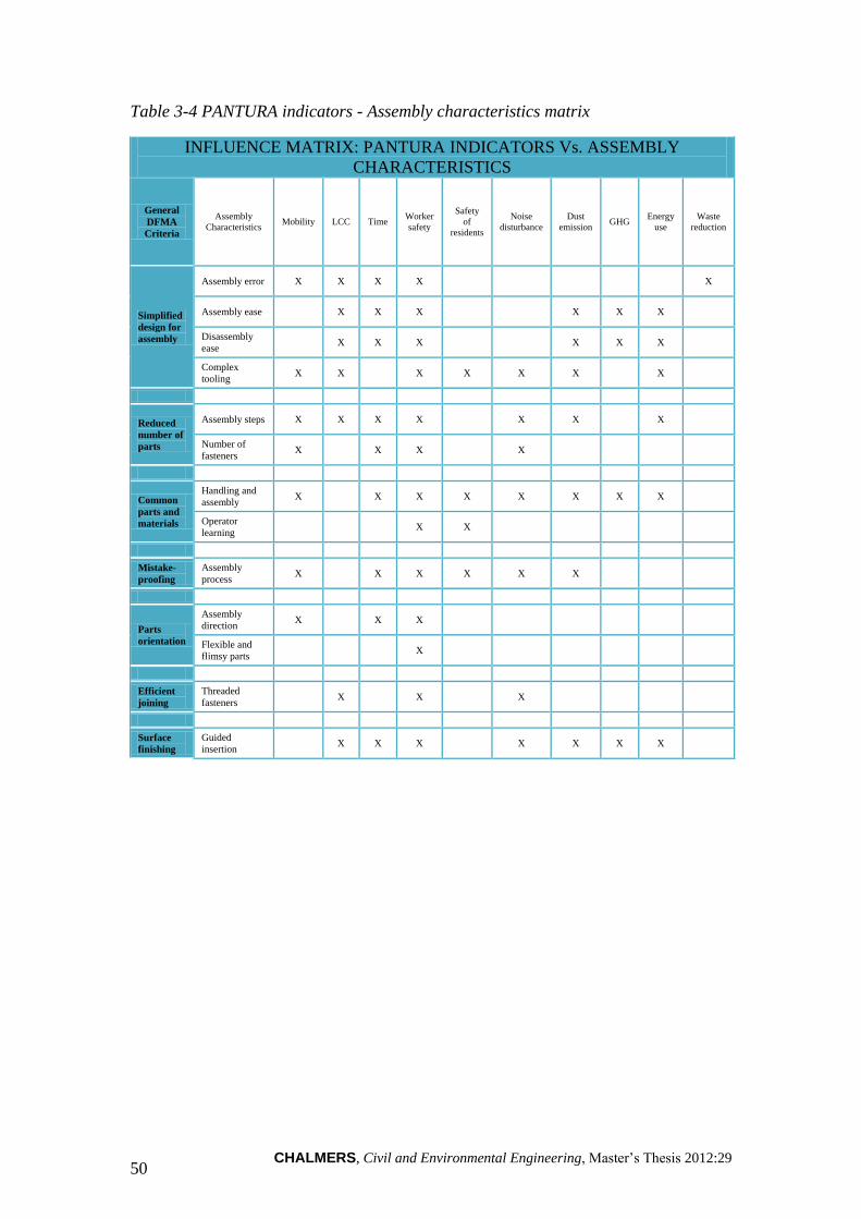
CHALMERS, Civil and Environmental Engineering, Master’s Thesis 2012:29 50
Table 3-4 PANTURA indicators - Assembly characteristics matrix
INFLUENCE MATRIX: PANTURA INDICATORS Vs. ASSEMBLY
CHARACTERISTICS
General
DFMA
Criteria
Assembly
Characteristics Mobility LCC Time
Worker
safety
Safety
of
residents
Noise
disturbance
Dust
emission GHG
Energy
use
Waste
reduction
Simplified
design for
assembly
Assembly error X X X X X
Assembly ease X X X X X X
Disassembly
ease X X X X X X
Complex
tooling X X X X X X X
Reduced
number of
parts
Assembly steps X X X X X X X
Number of
fasteners X X X X
Common
parts and
materials
Handling and
assembly X X X X X X X X
Operator
learning X X
Mistake-
proofing
Assembly
process X X X X X X
Parts
orientation
Assembly
direction X X X
Flexible and
flimsy parts X
Efficient
joining
Threaded
fasteners X X X
Surface
finishing
Guided
insertion X X X X X X X

CHALMERS, Civil and Environmental Engineering, Master’s Thesis 2012:29
51
4 Review of industrialized assembly methods
Different varieties of assembly techniques and methods of interest can be identified
by conducting study visits, reading industry brochures, from electronic sources and
careful day to day observations. Though, the most important achievement of this
research is measured by the suitability of the methods for convenient evaluation. As a
consequence, the required methods of assembly in this study are those with clear rules
and procedures which makes simplifies identification of their features during the
evaluation and ready for easy adoption into bridge construction. Some of such kinds
of assembly methods are presented together with technical concepts developed for an
easy assembly and construction of fibre reinforced bridges and bridge decks.
4.1 ConXtech structural steel space frame systems
ConXLTM
and ConXRTM
are the two innovative space frame systems devised by
ConXtech, steel structures manufacturer based in the United States. The systems can
be used for the construction of commercial office buildings, hospitals, blast resistance
structures etc and are currently being used for the construction of naval lodges that
cover up to 146,500 GSF whose framing is completed within 25 working days.
ConXtech's space frame systems deliver an innovative yet commercially viable
alternative to traditional building methods. ConXtech devises a systemized approach
to building design by utilizing the advantage of standardizing structural components
and a wide range of robust connectors. This yields a simplified structural system that
meets the required structural criteria simultaneously (JJeong, 2011). Apart from its
suitability for shorter spanned structures and the use of bolts and fasteners in ConXR,
the two space frame systems use similar assembly principles. Thus for the sake of
demonstration of the techniques and avoid redundant evaluation, the ConXL framing
system is used.
Its flexible configurability makes ConXL well suited to meet certain project
requirements needed when constructing commercial and office buildings, hospitals,
military structures, schools, parking tents, data centres and industrial markets. The
ConXL System applies technology to the building industry and results in improved
efficiency. This structural space frame systems approach is made possible by
employing automated and efficient processes, from design through fabrication,
shipping and field assembly (JJeong, 2011).
Apart from the structural viability of the system, the technology provided by
ConXtech also allows simple integration of other modular or factory-built building
components. The compatibility of the system with other modular structural parts is as
such important and the inherent precision of ConXtech system allows this required
compatibility (JJeong, 2011).
Key Advantages of the system
The benefits which can be sought from this structural system are presented in JJeong
(2011). The ones which are in line with the focus and purpose of this master thesis are
outlined herein under.
The structural simplicity of the system does not compromise the robustness of
the frame system. With its structural simplicity there is an inherent seismic,
blast and progressive collapse resistance.

CHALMERS, Civil and Environmental Engineering, Master’s Thesis 2012:29 52
The redundant distribution of moment frames can bring foundation savings
and the easy installation lowers the assembly cost of the structural system. The
aggregate of these two reduces total cost of the project (total installed cost)
when compared to conventional structural alternatives.
The simplicity and precision of the connection methods enables faster erection
when compared to the traditional assembly with bolts and nuts. Rapidness of
the construction can be improved two to five fold when compared to other
conventional structural alternatives.
On-site material handling and storage is minimized because of sequential
delivery of structural components.
By design, the ConXL system is made to eliminate the need for field welding.
Structural components can be assembled by easily lowering and locking into
one another at their joint spots.
The system inherently prevents risks of error associated with on-site assembly.
The joint spots are welded at their precise location as information from
electronic CAD/CAM files and Building Information Models (BIM) are fed
into the system. This thereby increases the precision of the assembly and
reduces the risk of human error and need for rework.
No bracings, diagonal members and shear walls are applied to ensure
structural stability. This allows aesthetic and architectural design freedom.
Despite the difficulty to maintain strict degrees of installation accuracy as
listed on a design, ConXL has a superior dimensional tolerance to
accommodate assembly inaccuracies. This Brings high quality, efficient
installations and satisfactory tight fit.
The demand to build high quality sustainable buildings is evident. ConXL
System components are manufactured in a highly automated manufacturing
facility where technology minimizes waste and carbon emissions. The
simplified and easy on-site assembly requires minimal extent of human labor
and construction equipment usage resulting in a reduced carbon footprint. The
system also makes use of durable materials; that are efficiently designed both
for assembly, disassembly and reuse.
Core Frame Components
The structural frame of a building constructed by the ConXL system is referred to as a
“Chassis”, as the system simplifies the structural frame to a unified system of beams,
columns and other structural components. This “chassis” comprised of a finite set of
systemized components:

CHALMERS, Civil and Environmental Engineering, Master’s Thesis 2012:29
53
a. HSS tube or built-up box columns (see Figure 4-1)
Figure 4-1 ConXR and ConXL columns (JJeong, 2011)
b. Wide flange beams (see Figure 4-2)
Figure 4-2 ConXR and ConXL wide flange beams (JJeong, 2011)
c. Two patented interlocking joints, one which forms a bi-axial moment
connection (collar), and the other an innovative gravity connection. Both
connections are easily assembled by lowering and locking beams into place
on-site and require no field “cut-and-fit” or welding associated with
conventional steel systems (see Figure 4-3).

CHALMERS, Civil and Environmental Engineering, Master’s Thesis 2012:29 54
Figure 4-3 Connection Collar (JJeong, 2011)
4.1.1 On-site assembly techniques for composite FRP-steel bridges
The following technical concepts are developed for the construction of composite
FRP-steel bridges and are proposed for use in projects that are in line with
PANTURA goals. The bridge concepts are composites of high-performance
construction materials, such as fibre reinforced polymer (FRP) composites and steel
girders. In the last decade, the use of FRP composite materials has grown widely in
bridge construction and one application of composite materials for bridges is FRP
decks lying on conventional steel girders. Composite FRP decks rested on steel
girders are appealing in new construction of bridges where the demands are fast
erection time, light weight and corrosion resistance. Therefore the development of on-
site assembly techniques, such as the technical concepts presented hereunder, are
points of attraction in the contemporary construction industry.
a. Technical concept 1: Snap-fit connection between FRP deck
and steel girders
The connections between the girders and the deck are conducted by snap-fit
connections. Snap-fit steel tubes are welded on the girders. Holes are cut from the
bottom plate of the deck and the deck is fitted from above. The holes in the bottom
flange are not cut at the intersection points between the flanges and the webs of the
decks but on the hollow sections. The connection is illustrated in Figure 4-4.

CHALMERS, Civil and Environmental Engineering, Master’s Thesis 2012:29
55
Figure 4-4 Snap-fit connection between steel girders and FRP deck
The procedures prescribed for this technical concept are:
1. FRP deck is prefabricated in panels with the holes cut on the bottom flange
and delivered on-site
2. The snap-fit steel tubes are welded off-site and transported to the site
3. After the steel girders are brought in place, the FRP deck is lifted and
pressed to the girders
b. Technical concept 2: Bolted connection between FRP deck and
steel girders
This connection concept is done by means of bolts welded on the longitudinal steel
girders and FRP sections with holes cut on the top flanges where the bolts are inserted
(see Figure 4-5).
FRP deck
Longitudinal Steel girders
Pultruded FRP element
Welded bolts
Figure 4-5 Bolted connection between FRP deck and the steel girders
The steps of installation for this connection are:
1. Bolts are welded to the steel girders off-site and lifted to place
2. Decks are lifted and rested on the steel girders
3. The FRP element is inserted and the bolts are fastened on-site
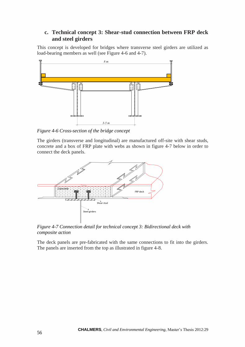
CHALMERS, Civil and Environmental Engineering, Master’s Thesis 2012:29 56
c. Technical concept 3: Shear-stud connection between FRP deck
and steel girders
This concept is developed for bridges where transverse steel girders are utilized as
load-bearing members as well (see Figure 4-6 and 4-7).
3-5 m
8 m
Figure 4-6 Cross-section of the bridge concept
The girders (transverse and longitudinal) are manufactured off-site with shear studs,
concrete and a box of FRP plate with webs as shown in figure 4-7 below in order to
connect the deck panels.
FRP deckConcrete
Steel girders
Shear stud
Figure 4-7 Connection detail for technical concept 3: Bidirectional deck with
composite action
The deck panels are pre-fabricated with the same connections to fit into the girders.
The panels are inserted from the top as illustrated in figure 4-8.

CHALMERS, Civil and Environmental Engineering, Master’s Thesis 2012:29
57
Deck Panel 1
Deck Panel 2 Deck Panel 3
Bolts
Filled with concrete
Figure 4-8 Illustration of insertion of deck panels to the superstructure
d. Technical concept 4: Bar-and-slot and snap-fit connections
between FRP deck panels
There are two different deck-to-deck connection methods categorized under this
technical concept. Bar-and-slot connection system is materialized by means of a bar-
and-slot which resembles ball-and-socket joint. In this connection method each panel
is slide onto the previous one by tilting it 45 degrees, inserting the bar in the slot, and
letting self-weight close the connection. Furthermore, this connection acts
transversally as a joint, allowing the deck to adapt longitudinally to girder deflections.
Figure 4-9 Bar-and-slot deck-to-deck panel connection
The other deck-to-deck connection is materialized by means of a snap-fit system, so
that once deck sections are placed, interaction between twin tongues and grooves fixes
relative displacements lengthwise of the bridge. Crosswise relative displacements are
prevented by the deck to girder connection.

CHALMERS, Civil and Environmental Engineering, Master’s Thesis 2012:29 58
Figure 4-10 Snap-fit deck-to-deck panel connection

CHALMERS, Civil and Environmental Engineering, Master’s Thesis 2012:29
59
5 Evaluation Methods
Evaluating a phenomenon (specifically an assembly method) requires the use of
certain parameters which make use of a framework of predefined criteria. If results of
an evaluation are to be compared, there shall be similar ground on which the different
scenarios are measured. The comparison between the general performances of the
different assembly techniques presented in Chapter 4 is beyond the scope of this
work, as they are applicable in different work settings and project conditions. In this
section, an evaluation platform will be established based on which the assessed
assembly methods and technical concepts are evaluated. The knowledge inseminated
in earlier chapters about the principles of DFMA, PANTURA requirements and
assembly methods and techniques will be used integrally in this section to establish
the evaluation setup. The DFMA characteristics presented in Section 3.2.1 will be
used as criteria when evaluating the assembly methods or technical concepts.
Analogously, the assembly methods and technical concepts are also required to fulfil
these criteria in order for them to be DFMA supportive.
5.1 Approach and choice of evaluation method
As stated by Daetz (1987 in Eskilander, 2001), in order to achieve consistent quality
in products, certain attributes of interest have to be measured and results have to be
tracked to maintain quality or bring further improvements. In a multi criteria industry,
drawing these attributes of interest can be a challenge as there is a web of varied
aspects and interests from the actors involved in the construction context. In such a
situation, it is imperative to devise and follow a structured approach towards the
challenge.
5.1.1 The approach
In order to successfully evaluate the assembly methods and technical concepts, it is
vital to know the requirements of the assembly process in question. For example
considering the assembly of prefabricated concrete elements, it involves handling of
large and heavy concrete members. This can be presented as one of the bottlenecks in
the assembly process. According to an interviewee from NCC, in situ casting of
concrete, on the other hand, may have an inherent construction difficulty during
reinforcement placing and fastening. Due to the obvious variation in work settings
between the two, the bottlenecks associated with the respective construction
methodology are also different in type. In a view to lay common playground for the
assembly methods to be assessed without limiting the extent of the research, only on-
site assembly or installation of bridge parts is considered.
According to Eskilander (2001), there can be used different approaches of evaluating
a product, quantitative or qualitative. A quantitative evaluation involves measuring
the performance of a product or a system (e.g. in terms of the time required and cost
incurred for execution of a certain task). In an assembly perspective, quantitative
evaluations do not provide specific and objective advices and procedures to design
parts for an efficient assembly system. Apparently a DFMA tool gives an indication
or qualitative information on how complex a product is, from an assembly point of
view, in order to render it simpler and consequently making it less expensive
(Lahtinen, 2011). The mere numerical results from a quantitative evaluation do not
provide explicit information about the preferred solution for the assembly process
(Eskilander, 2001).

CHALMERS, Civil and Environmental Engineering, Master’s Thesis 2012:29 60
A typical example of quantitative evaluation method is the one forwarded by
Boothroyd and Dewhurst (1987 presented in Eskilander, 2001). In order to measure
the performance of a design and product from an assembly view point, the method, in
this example, uses a DFA index given by the equation,
DFA Index =
Where: Nm = theoretical minimum number of parts
tm = ideal minimum assembly time per part
ta = estimated total assembly time
According to the equation, a design or a product with low index, experiences at least
one, two or all of the three downsides in its system, while a high index value shows a
design that is optimal in the aspect of assembly. These downsides can be a large
number of parts, extended assembly time per part and extended total time required for
the assembly of the entire product. The results of the DFA index are then used to
determine which scenarios require careful attention and pass preliminary decisions to
eliminate or redesign the redundant assembly part (Geng, 2004), which requires
extended time of assembly and incurs extra cost.
As shown by the example above, a quantitative method requires numerical data and
parameters of measurement, and in output it provides a numerical estimated time and
cost (Jürisoo and Staaf, 2007). These results have to be interpreted for their
implication in the manufacturing or assembly.
On the other hand, a qualitative measure is based on a set of criteria or conditions that
a product preferably should fulfill to fit in an assembly process. It can involve certain
steps of measuring how far the product is from the ideal solution (Eskilander, 2001).
An ideal solution in this thesis work refers to an assembly technique which fulfills all
the DFMA characteristics translated into each PANTURA indicators. The process and
assembly part feature considerations employed in qualitative evaluations makes it
preferable for studies and researches aiming to provide explicit information about
preferred solutions for assembly processes.
It is evident that, not all DFMA criteria can be fulfilled by a certain assembly
technique, leaving it difficult to make relative judgment among the different
techniques. Thus, when conducting an evaluation with qualitative measures,
performance comparison will rather be made with the extent to which the DFMA
behaviors in each PANTURA indicator are fulfilled by the assembly methods. So in
this work, similar ideology of qualitative evaluation is considered as in Eskilander
(2001), in which qualitative evaluation is performed based on a set of criteria that is
used to decide if the assembly method does satisfy the DFMA characteristics used in
the translation of each PANTURA indicators.
The following figure shows the procedure and flowchart used in the evaluation of the
assessed assembly methods and technical concepts. Treatment of the subjects in each
box constitutes the different chapters and sections in this thesis work.

CHALMERS, Civil and Environmental Engineering, Master’s Thesis 2012:29
61
Figure 5-1: Evaluation flowchart
5.1.2 Choice of evaluation method
According to Eskilander and Carlsson (1998 stated in Lahtinen, 2011) and Harik and
Sahmrani (2010), an applicable DFMA tool should fulfill the requirements listed
herein under. These attributes can be considered as critical success factors for a
successful implementation of DFMA method.

CHALMERS, Civil and Environmental Engineering, Master’s Thesis 2012:29 62
Table 5-1 DFMA critical success factors and their attributes
Critical success factors Attributes
Present a non-patterned approach to
problem solving
Qualitative and Quantitative
Include rules and techniques that will
facilitate economic manufacture and
improve assembly techniques at reduced
cost, and easy handling of components
Qualitative
Promotes appropriate selection of
materials and processes
Qualitative and Quantitative
Support for cross-functional teams Qualitative
Enable transfer of knowledge Qualitative
Include cost analysis Quantitative
Include product’s quality assurance
Include views of manufacturability and
assembly evaluation
Qualitative and Quantitative
Provide design suggestions and
desirable solutions
Qualitative
Prohibit unnecessary design variants Qualitative and Quantitative
Be user friendly Qualitative and Quantitative
An ideal DFMA method should include the aforementioned requirements in order to
enable evaluation of a design, manufacturing or assembly process and provide
suggestions for possible improvements in a successful way (Lahtinen, 2011). As
depicted in the table, for its successful application, DFMA should follow an equally
qualitative approach towards the evaluation of products and methods (Eskilander,
2001) so as to provide design suggestions and desirable solutions that solves problems
in the area they are applied.
There are certain criteria and indicators that are framed in the PANTURA context.
The construction or assembly of bridges has to take these indicators into account, for
it to be successful in meeting the PANTURA goals. According to the detail
description of PANTURA indicators in Section 3.2.2, apart from quantitative
measures most important of the indicators such as total life cycle cost, workers’ and
residents’ safety, construction noise, traffic mobility, construction dust, carbon
footprint and waste also require a significant qualitative analysis.
For the fact that great deal of cost is incurred during the assembly block of a
construction (Jürisoo and Staaf, 2007) and due to the more qualitative feature of the

CHALMERS, Civil and Environmental Engineering, Master’s Thesis 2012:29
63
PANTURA requirements, coupled with the possibilities in qualitative approaches to
analyse assembly processes and pass recommendations on features of an assembly
part, exclusive emphasis will be given to assembly processes experienced during
actual construction. The scope of this chapter will be restrained to qualitative
evaluation of the assembly methods and technical concepts presented in Chapter 4.
5.2 Qualitative methods of evaluation for manufacturing
and assembly
As it was explained in earlier section, the evaluation guidelines used in DFMA
methods follow a more qualitative strategy. So far developed DFMA methodologies
are qualitative and are often based on descriptive general guidelines (Harik and
Sahmrani, 2010). In such cases of qualitative measurement, a profound knowledge
and experience of designers, assemblers and manufacturers is crucial (Harik and
Sahmrani, 2010). In qualitative evaluations, products are assessed for certain
performance indicators in the different levels of the design process (Giachetti, 1999).
Evaluations are conducted to assess the subject matter according to few criteria, which
are compiled from certain objectives, and propose the most front ranked conceptual
design (Lahtinen, 2011).
To recapitulate, when Concurrent Engineering is in place, assembly issues will need
to be brought in the design process of the parts. The criteria considered when
evaluating a certain assembly method/process should also include parameters that
belong to both the manufacturing and assembly phases. When other industries refer to
manufacturing, they are simultaneously considering the assembly process inherent in
the production of goods or parts. On the other hand, even though tasks in traditional
construction are usually performed on-site, contemporary construction industry is
undergoing a far more different experience. For a better demonstration, consider the
construction of a civil structure by using prefab concrete elements. Due to the
bulkiness of the assembly parts (e.g. prefab concrete slab of a bridge deck), their
manufacturing has to be done off site. This gives the construction industry a unique
feature as the manufacturing of the prefab elements and the sequential assembly
process are two physically separated but mutually influential tasks. Thus, when
dealing with DFMA in construction, there should be a more customized approach
towards setting criteria that exclusively belong to the manufacture and assembly
blocks. But it is not easy to define such a criterion that has an exclusive influence
either on manufacturing or assembly blocks of a construction. With the difficulties
associated with it, this thesis makes use of the separate manufacturing and assembly
characteristics that are already discussed in Section 3.2.1 and 3.2.2 as a basis for the
evaluation of assembly methods and technical concepts.
According to Harik and Sahmrani (2010) and few more literatures, there are various
types of DFMA methods in place. Despite the variety of their approach, all of them
share similar concepts; in a way that they evaluate processes and results with respect
to certain common requirements that need to be fulfilled. The various DFM, DFA or
DFMA methods uses a combination of different design objectives such as Quality
Function Deployment, manufacturing analyses, design to cost, parts
interchangeability, manufacturability, interactive creation of geometric models, and
design to feature recognition and generate proposals to re-design. Of the several
methods discussed in different literatures, in this thesis work, a qualitative method of
evaluation which is analogous to the method underpinned by Harik and Sahmrani

CHALMERS, Civil and Environmental Engineering, Master’s Thesis 2012:29 64
(2010) will be followed. Primarily, the separate treatment of manufacturing and
assembly characteristics for the evaluation of methods and processes emanates from
the method of evaluation used in Harik and Sahmrani (2010). The method first
identifies important criteria then assigns weights to the respective parameters as to
portray their effect on a given assembly process or method. Similarly in this thesis
work, assignment of weights to each individual manufacturing and assembly
characteristics is performed in order to reflect their perceived relevance in bridge
construction and the subsequent influence they impose on the respective PANTURA
indicators they are categorized into.
5.3 Assignment of weights and value engineering
In this section, detailed explanation of two separate weight studies and the method
chosen for scoring the assembly techniques will be presented. As it was explained in
earlier sections, the evaluation platform developed in this thesis work is a combination
of the method underpinned by Harik and Sahmrani (2010) with evaluation criteria
from DFMA studies (presented in Chapter 2 and 3) and a different choice of
assignment of weights.
There were various difficulties encountered during characterization of the general
DFMA criteria. Due to their intricate nature and dependability among each other, it is
practically difficult to draw a clear distinctive line between the different general
DFMA criteria and find exclusive traits and characteristics for each of them. Thus,
assignment of weights for each characteristics and traits may require a subjective
approach based on experience and importance of the traits in bridge engineering. As
there is limited background on this area of study in the construction sector, there is
little or no benchmarking by which such studies could easily grasp an already
established knowledge for an improved adoption and implementation. In order to
compensate the risk of biased evaluation outputs due to weights emanating from
inexperienced and unfounded decisions, narrow range of weights is used. The weights
assigned to each manufacturing and assembly characteristics ranges from 1 to 5
depending on the weak or strong influence they impose on the respective PANTURA
indicators they are translated into. When evaluating an assembly method for a specific
PANTURA indicator, the characteristics that are considered to be directly linked to
the indicator in question can be weighted highly, while the ones which have a weak
link with their parent indicator will be weighted as 1.
The following tables (Table 5-2 and 5-3) summarize the weights assigned to each
manufacturing and assembly characteristics under the individual PANTURA
indicators. The weightage reflects the perceived direct/strong or indirect/weak link
between the characteristics and respective impact of the characteristics on
manufacturing or assembly of parts.
Different stakeholder groups, decision makers and design professionals may tend to
have varied interests and perceptions about the individual impacts of the DFMA
characteristics on the PANTURA goals. As a result they can assign different values of
weights depending on experiences in their fields of expertise. The assumption that
lays the basis for the weighting in this specific context of the thesis work is presented
in Appendix A.

CHALMERS, Civil and Environmental Engineering, Master’s Thesis 2012:29
65
Table 5-2 Weights assigned to manufacturing characteristics
WEIGHTS: MANUFACTURING CHARACTERISTICS
General
DFMA
Criteria
Manufacturing
Characteristics Mobility LCC Time
Worker
safety
Safety
of
residents
Noise
disturbance
Dust
emission GHG
Energy
use
Waste
reduction
Simplified
design for
manufacturing
Fabrication
steps 5 3 3 1
Parts
performance 5 3
Process
compatibility 2 3 3 1
Parts number Combining
parts 5 3 2 2 2
Common
parts and
materials
Material
types 5 5 5 5 5
Additional
experiment 1 1 1
Mistake-proof
product design
Parts'
physiology 2 3
Stops,
notches,
guides
1 1
Axes
symmetry 1 1
Ease of parts
orientation
handling and
assembly
Surface
property 2 2 4
Sticky and
slippery parts 3 5
Parts weight 5 3 5 2 3
Efficient
joining
Matched
fastening 4 1
Surface
finishing Tolerances 2 1 1

CHALMERS, Civil and Environmental Engineering, Master’s Thesis 2012:29 66
Table 5-3 Weights assigned to assembly characteristics
WEIGHTS: ASSEMBLY CHARACTERISTICS
General
DFMA
Criteria
Assembly
Characteristics Mobility LCC Time
Worker
safety
Safety
of
residents
Noise
disturbance
Dust
emission GHG
Energy
use
Waste
reduction
Simplified
design for
assembly
Assembly error 5 3 3 5 3
Assembly ease 1 2 3 1 2 2
Disassembly
ease 2 1 4 3 2 2
Complex
tooling 4 1 2 3 3 2 1
Reduced
number of
parts
Assembly steps 4 1 1 1 2 2 1
Number of
fasteners 3 1 1 3
Common
parts and
materials
Handling and
assembly 2 2 3 2 1 1 1 1
Operator
learning 1 1
Mistake-
proofing
Assembly
process 1 1 1 2 1 1
Parts
orientation
Assembly
direction 5 3 4
Flexible and
flimsy parts 4
Efficient
joining
Threaded
fasteners 2 1 1
Surface
finishing
Guided
insertion 1 1 2 1 1 1 1
For ease of analysis and demonstration, the desired and undesired traits of an
assembly method (shown in Table 3-1 and 3-2) are given with a score of 0 and 1
respectively according to what has been observed in the assembly method in question.
For example, if an assembly method or technical concept is perceived to possess a
desired trait it will attain a score of 1. Whenever undesired traits are noticed, the
respective assembly method gets a score of 0.
5.4 The evaluation and interpretation of results
In order to be able to avoid as much subjective considerations as possible, certain
assumptions are made. These assumptions are important to consolidate series of
uniform considerations when evaluating the assembly techniques. There are factors
that are perceived to have the potential of deviating results of the evaluations. One
example of these can be work settings in which the assembly processes are assumed
to take place. Work settings do have a significant influence on the efficiency of an
assembly process. A typical manifestation of this is the efficiency level which can be
obtained by implementing improved assembly techniques such as automation and the
use of robots. Automation can increase efficiency of assembly or at least may bring
the same result as what would have been accomplished by reducing the number of
parts to be assembled (Sigo, 2007). Manually workers are more flexible than
mechanical assembly equipment and therefore the demands and consequently the

CHALMERS, Civil and Environmental Engineering, Master’s Thesis 2012:29
67
criteria for designing the product for manual assembly are different from that for
automatic assembly (Eskilander, 2001). So it is mandatory to consider similar work
settings when evaluating an assembly method as this helps to possess an easy control
over the results of the evaluation. So this thesis work assumes manual assembly
methodology (involving handling and tooling) for the analysis and evaluation of the
assembly techniques. In other words manual assembly methodology is taken as the
common work setting when assembly techniques are analyzed and evaluated.
The evaluation of the assessed assembly techniques was made in a table format
containing the important parameters, characteristics and criteria that are listed in
Tables 3-1 and 3-2 and weights summarized in Tables 5-2 and 5-3. As shown in the
referenced tables, the manufacturing and assembly characteristics forms the general
DFMA criteria for the construction/assembly of bridges and be the basis of evaluation
of the techniques of assembly. The evaluation of the assembly techniques is
performed by assigning scores to the respective manufacturing and assembly
characteristics translated into PANTURA indicators. In Appendix B sets of tables
showing the evaluation of each assembly techniques are presented. The tables are
structured in such a way that the general DFMA criteria and respective characteristics
with assigned weights of their perceived impact on the indicator in question are shown
together with a scoring based on the desirability or undesirability of the assembly
techniques in meeting each specific manufacturing and assembly characteristics. The
evaluation has been done separately according to both manufacturing and assembly
requirements. Later in the process, results of the evaluation under each PANTURA
indicator has been aggregated to see how much an assembly technique fulfills the
DFMA requirements mentioned under each PANTURA indicator.
For the sake of demonstrating final results of the evaluation, the aggregated scores
attained by each assembly method and technical concept are presented in table 5-4.

CHALMERS, Civil and Environmental Engineering, Master’s Thesis 2012:29 68
Table 5-4 Summary of evaluation
For the explanation of how the evaluation process works and how results can be
translated, we can take the evaluation of one of the techniques for a certain
PANTURA indicator during both blocks of manufacturing and assembly. As can be
noted in the table, results of the evaluation are presented as a score attained by an
assembly method out of a maximum possible that can be achieved. For example if the
evaluation of technical concept 1 (TC1) for mobility during its manufacturing phase is
considered, one can see from the summary table that it attains a score of 5 out of a
possible 7 (that means 5/7). Considering the process of assembly using the same
technical concept, mobility is said to be interrupted by 33, 33%, as the score attained
by the assembly method in question is 16 out of a maximum 24. Here it is worth
demonstrating that an ideal assembly method which results in a virtually no traffic
disruption during assembly process has to reveal a result of 24/24. The other
evaluation results can also be interpreted in the same way. Finally the scores attained
by each assembly methods for every indicator during both manufacturing and
assembly are summed and portrayed as a result which shows how much is the
assembly method in question is supportive to a specified PANTURA indicator in a
DFMA manner. As to reinforce this interpretation of the results, it is again important
to consider an example. Considering the same example used earlier, Technical
Concept 1 attains a result of 21 (5+16) from a total maximum of 31 (7+24). This
result shows the extent to which the assembly method in question fulfils the
requirements of mobility in a DFMA manner.
Evaluation results of the other assembly methods and technical concepts can be
interpreted in the same way for each PANTURA indicator in relation to
General DFMA
Criteria
Manufacturing
Characteristics
22 15
SUMMARY OF EVALUATIONS
TECHNICAL CONCEPTS 1-4 & CONXL
Max Possible (Manufacturing and Assembly) 31 35 33 53 8 12 21 23
8 3
Total Score (Manufacturing and Assembly) 29 17 30 45 8 12 21 11 10 8
Max Possible (Assembly) 24 11 15 32 8 12 11 6
12
Total Score (Assembly) 24 11 15 32 8 12 11 6 8 3
15
TC4
Total Score (Manufacturing) 5 6 15 13 0 0 10 5 2 5
Max Possible (Manufacturing) 7 24 18 21 0 0 10 17
Max Possible (Manufacturing and Assembly)
14
31 35 33 53 8 12 21 23
8
22
3
Total Score (Manufacturing and Assembly) 7 6 15 29 5 8 13 3 5 8
Max Possible (Assembly) 24 11 15 32 8 12 11 6
10 17 14 12
Total Score (Assembly) 7 6 10 22 5 8 5 1 3 3
15
TC1
TC2
TC3
Total Score (Manufacturing) 0 0 5 7 0 0 8 2 2 5
Max Possible (Manufacturing) 7 24 18 21 0
Max Possible (Manufacturing and Assembly)
0
31 35 33 53 8 12 21 23
8
22
Total Score (Manufacturing)
3
Total Score (Manufacturing and Assembly) 25 11 25 44 8 11 21 11 10 8
Max Possible (Assembly) 24 11 15 32 8 12 11 6
2
14 12
Total Score (Assembly) 20 9 15 31 8 11 11 6 8 3
Max Possible (Manufacturing) 7 24 18 21 0 0 10 17
9
5 2 10 13 0 0 10 5
824 11 15 32 8 12 11 6 3
5
8 8
Max Possible (Manufacturing and Assembly) 31 22 33 53 8 12 21 11 10 13
Total Score (Manufacturing and Assembly) 21 11 24 46 8 9 18
Max Possible (Assembly)
Mobility LCC TimeWaste
reductionWorker safety
Safety of
residents
Noise
disturbanceDust emission GHG Energy use
Max Possible (Manufacturing) 7 11 18 21
Total Score (Manufacturing) 5 2 10 18
0 0 10 5 2 10
0 10 5 2 50
Total Score (Assembly) 16 9 14 28 8 9 8 4 6 3
CONXL
Total Score (Manufacturing) 2 11 15 13 0 0 5
Total Score (Assembly) 20 11 15 31 8 7 9 6 7 3
Max Possible (Assembly) 24 11 32 8 12 11 6 8 3
5 5 8
Max Possible (Manufacturing) 7 24 18 21 0 0 10 17 14 12
12 11
Max Possible (Manufacturing and Assembly) 31 35 33 53 8 12 21 23 22 15
Total Score (Manufacturing and Assembly) 22 22 30 44 8 7 14 11
15

CHALMERS, Civil and Environmental Engineering, Master’s Thesis 2012:29
69
manufacturing and assembly processes. Results of the evaluation can thus be
compared in three different levels by making use of manufacturing considerations,
assembly considerations and DFMA considerations. Results of each PANTURA
indicator for manufacturing, assembly and combinations of the two can be compared
with their respective piers for other technical concepts.

CHALMERS, Civil and Environmental Engineering, Master’s Thesis 2012:29 70
6 Discussion
The tasks that have been covered in this thesis work are intertwined with each other,
leaving the explanation of the different parts a challenging task without mentioning
the relation with the others. The following section reflects upon the importance of this
thesis work, difficulties encountered during the course of the work and the results that
have been achieved.
From a general perspective, the aim of this master thesis is to devise and test a method
of assessment of bridge assembly techniques that contribute to sustainability in urban
environment. During the course work certain challenges were encountered impeding
the fulfillment of the aims to the desired extent. Among the various obstacles, the
most important ones are the difficulties faced during tasks of reviewing design
methods and criteria for bridge construction, customizing/translating other industry
concepts and transferring knowledge into construction, searching applicable and
developed assembly methods, finding appropriate evaluation methods, and finally
performing the actual evaluation. There are only few previously conducted works or
already established knowledge that can be related to most of the tasks in this master
thesis. For example, the transformation and application of DFMA as a design method
and an evaluation tool in the construction industry is a recent development. Therefore
undertaking such a task should be executed with all the necessary care. Furthermore,
the results obtained from such a study should be open for discussion in order to be
able to funnel more ingredients into the tasks for the betterment of the results. Certain
major points could be raised in conjunction with the aforementioned tasks and are
discussed below.
The aim of identifying manufacturing and assembly design principles for construction
industry use requires performing a task of transferring the knowledge of design
methods and objectives in other industries. This in turn requires a widespread study of
literatures concerning design objectives and manufacturing-assembly principles.
Furthermore, with a focus on bridge construction, there is a need for an understanding
of the bottlenecks and criteria applicable for the subject industry. The design method
that is underpinned in this master thesis is a design decision support tool which has
been used and proven for its contribution in reducing cost, cutting wastes and bringing
system efficiency. However, the true essence of DFMA applications is not clear and
their cost-benefit analysis does not present a vivid picture of application costs being
lower than benefits attained. This, perhaps, leaves a potential risk for users of the
tools. Moreover, the literatures researched in the area of DFMA are mostly written by
founders of the concept and are obviously favoring the application of the associated
tools regardless of different industry settings.
As they are formulated to be applied in a different production scenario, the principles
and guidelines followed in other industries when working with DFM, DFA, and
DFMA methods portray a setup which is different from what is needed in the
construction. Therefore selection of design criteria and objectives has been made
based on their usefulness and applicability in the context of on-site bridge assembly.
The choice and selection is based on an acquired knowledge in the area of bridges
construction. Performing such a task of selection requires a profound experience and
knowledge in the subject matter as there are plenty of assumptions to make and
multiple decisions to pass. Due to this fact, the principles of DFMA can be applied in
many different perspectives according to what is being perceived by each practitioners
involved in the task of devising such design methods. Apart from this, some of the
CHALMERS, Civil and Environmental Engineering, Master’s Thesis 2012:29
71
principles and guidelines are less important to be considered in the design and
assembly of bridge parts. For example compared to the material types used in
manufacturing or number of assembly parts, additional experiments needed for testing
the performance of components does not have major effect on actual assembly on-site
and impose a low weighted impact on some of the PANTURA indicators directly
related to on-site construction processes.
Another challenge in the implementation of DFMA systems is the difficulty to focus
on a single project phase while working with such a system in construction, as DFMA
covers the entire project cycle (from design to assembly). It is also a challenging task
to synchronize between construction processes and DFMA systems because
construction process normally involves physically separated tasks which puts an
obstacle to implement DFMA systems in their natural iterative way. Re-consideration
of criteria seems to be only possible among construction projects while undergoing
certain project learning activities. But short and swift iterative processes between
manufacturing and assembly of construction elements within the same project can be
a challenge.
There are still more aspects to contemplate concerning the application of the design
methods into construction industry. Issues such as procurement systems that affect the
extent of involvement of professional personnel and client/project owners’ readiness
and patience to introduce such revolutionary changes are out of the scope of this
thesis work. Yet it is worth mentioning them briefly as they include important
concerns that put a demand on the current procurement systems being employed. For
example the absence of adequate incentives or lack of procurement system integration
for designers to work in collaboration with professionals from the different phases and
parts of projects in conjunction with the short time spent in the entire process of
procurement leaves a difficulty in the implementation of design methods such as
DFMA, as also stated by the interviewee from Skanska. To realize the benefits of
DFMA, engineers have to be able to perform designs for multiple criteria objectives.
For this, incentives and the required time for such extra measures has to be granted in
the procurement system thereby triggering designers to consider production issues
early in the product realization phases, so that important criteria such as in DFMA can
be achieved and societal issues prescribed in performance indicators like PANTURA
will be met.
Another setback is testing a conceptual design. Due to project specific issues a
construction design performed according to DFMA systems cannot be tested in the
same way as a small manufacturing product design routine would. However, the
usefulness and applicability of DFMA can be enhanced with the integration of 3D and
information modeling tools by allowing multiple criteria considerations early in the
design phase to assess and visualize the entire project form beginning to late stages.
The process of translation of the DFMA criteria into PANTURA indicators was
limited to a scenario where there is a perceived direct and strong relation between the
DFMA criteria and the PANTURA indicators in question. This avoids presence of
similar effects of characteristics in different PANTURA indicators thereby preventing
similar characteristics from being evaluated multiple times and result in a distorted
evaluation outcome. When devising the evaluation platform, the main issue was
finding an evaluation method which fits in the objectives set, since the PANTURA
indicators possess both qualitative and quantitative features. In accordance with the
range of available knowledge and data, a qualitative evaluation approach was chosen,

CHALMERS, Civil and Environmental Engineering, Master’s Thesis 2012:29 72
as it can be executed in a more simplified way and within shorter time than required
by a quantitative one, where data collection, categorization, analysis and manipulation
is an important aspect. The need of a deeper knowledge and project experience was
also reflected while choosing and working with an evaluation method. Part of the
evaluation process involves assignment of weights to the DFMA characteristics and
scoring the methods of assembly which requires a well-founded understanding on the
severity of each criterion in relation to bridge requirements and PANTURA goals and
also great deal of experience in bridge construction. Due to the assumptions made
during the course of evaluation, results of the evaluations performed in this thesis
work reflect a more subjective approach and evaluation results may portray different
numerical outputs according to the level of knowledge and experiences in working
with the assessed assembly methods and the weights given to each evaluation criteria.
But results of such an evaluation will remain to be subjective and open for discussion
unless tasks of scoring and assignment of weights are inspired by a well-founded
technical ground.
After presentation of few conceptual assembly techniques and methods to industry
practitioners involved in project PANTURA, some of them were decided to be not in
line with the primary objective setup at the commencement of this master thesis,
which are types of assembly methods from other industries that are well developed
with clear rules and procedures and ready for evaluation and easy adoption into bridge
construction. Apparently, most of the technics researched during the course of this
thesis work were at their early conceptual stages which make it difficult to draw
conclusions on how they appear to be during actual assembly and see their
applicability in bridge constructions without conducting further development.
Even though the combined effect of all these challenges cast its own shadow during
the course of this thesis work, there are important areas of strength and observed
applicability potentials of the concepts developed. The significant concepts that are
put forward in this research are the DFMA criteria used in the evaluation. These
evaluation criteria are presented as simplified demands that a product has to fulfill in
order to achieve an efficient and easy assembly system which does not cause rework
needs and assembly difficulties. Even though it is a challenging task to directly adapt
assembly techniques to construction industry usage, the guidelines and criteria used
during evaluation can be considered back in the design tasks when designing bridge
assembly parts.
The other manifestation of the significance of this research is the possibility to
attribute the conceptual and more theoretical PANTURA indicators with tangible and
measurable DFMA behaviors. This allows the evaluation methods to be more
applicable in the real world as the criteria used are features that can be observed and
learnt from experience in working with different assembly methods.
Few implications were also observed during the trials to improve the quality of the
evaluation results. As it was mentioned repeatedly, results of the evaluation are highly
dependent on the assignment of weights to the evaluation criteria and scoring of the
assembly methods. It would have been possible to achieve a more applicable and
realistic result if weights of the criteria were assigned in conjunction with decision
makers and industry practitioners. Looking into possibilities of evaluating with
intermediate scores, other than “0” and “1”, in a qualitative approach would also
benefit this thesis work as it helps to score methods in a way which better portrays
their actual performance. Finally, funneling as many number of evaluation features as
possible helps to frame a better set of desired manufacturing and assembly

CHALMERS, Civil and Environmental Engineering, Master’s Thesis 2012:29
73
characteristics, thus the PANTURA indicators can be translated more objectively and
evaluations undertaken in such a context will be more portraying real situations as
they are freed from bias and distortions.

CHALMERS, Civil and Environmental Engineering, Master’s Thesis 2012:29 74
7 Conclusion
A mere focus on reductions in direct costs and on time accomplishments through
rigorous checking of assembly activities has been a common practice in the
construction industry. When considering other sustainability concerns, for example
minimization of issues such as human work, traffic disruption and related social costs,
different approaches of attaining these needs should be followed. In this research
another dimension of resource efficiency and cutting costs has been assessed and
made possible by the use of DFMA methods. Even if it requires great deal of initial
investments, DFMA significantly facilitates attainment of the said goals for
organizations and firms who work in line with sustainability objectives.
As it has been repeatedly mentioned, there is a challenge in designing a product and
assembly process that fulfils all the DFMA requirements simultaneously. In such
circumstances, it is suggested to prioritize and categorize the criteria according to
requirements of stakeholders such as society, clients/owner, and environment. Such an
approach can ease decisions on what relevant objectives to consider during design
tasks. In conjunction, evaluations that rely on such criteria and objectives will have
their own influence on stakeholders at different levels. The same analogy goes to the
PANTURA indicators, as categorization of each of them according to stakeholder
preferences will lead to unbiased and realistic interpretations of the evaluation criteria
prescribed and results shown in this research. Moreover, early identification of
desirable product characteristics, product assembly issues and social cost
considerations is crucial for the construction industry to enjoy swift assemblies on-site
and address related concerns.
As it was manifested during the evaluation, further guidelines, product feature
requirements and improvement statements can be drawn for further developments of
the concepts and assembly technics. This attribute makes the prescribed DFMA
criteria applicable beyond a mere evaluation but also as suggestions for further
improvements in product developments.
It is evident that such industrial thinking and advanced design methods as the
assembly techniques and concept of DFMA have a contribution during brainstorming
new objectives and ideas to multi-faceted design tasks. It can also be concluded that
DFMA concept directs designers to do things the right way instead of doing the right
things, as the iterative procedure supported by the system allows a better
understanding among the actors involved, thereby feedbacks from every levels of
product development can be taken into consideration during redesign processes. With
this iterative nature of the task, industry practitioners will be able to enjoy the
possibilities of testing, selecting and developing best practices from all possibly
available “right ways of doing things”.

CHALMERS, Civil and Environmental Engineering, Master’s Thesis 2012:29
75
8 References
AEROSPACE MANUFACTURING AND DESIGN. 2011. Highlights of 2011
DFMA Forum [Online]. Available: http://www.onlineamd.com/aerospace-
energy-manufacturing-design-DFMA-amd-tes-071811.aspx [Accessed March
6 2012].
ASSOCIATION ON HIGHER EDUCATION AND DISABILITY. 2012. National
Service [Online]. Available: http://www.ahead.org/nsip [Accessed May 27
2012].
BIBBY, L. 2003. Improving design management techniques in construction.
BOOTHROYD DEWHURST INC. 2012. Design for Manufacture and Assembly
(DFMA®) [Online]. Available: http://www.dfma.com/software/index.html
[Accessed March 23 2012].
BOOTHROYD, G. 1994. Product design for manufacture and assembly. Computer-
Aided Design, 26, 505-520.
BOOTHROYD, G., DEWHURST, P. & KNIGHT, W. 2004. Product Design for
Manufacture and Assembly. New York: Marcel Dekker, Inc.
CROW, K. 1998. Design for Manufacturability/Assembly Guidelines [Online].
Available: http://www.npd-solutions.com/dfmguidelines.html [Accessed April
4 2012].
DEWHURST, N. P. Year. DFMA the Product, then Lean the Process. In:
International Forum on Design for Manufacture and Assembly, 2010
Providence, Rhode Island.
DEWHURST, N. P. 2011. Design first, lean second. Assembly, 54, 62-68.
DING, S. H. & ZHONG, P. S. 2011. Research of Advanced Manufacturing
Technology’s Impacts on Manufacturing Industry. Applied Mechanics and
Materials, 66, 174-178.
ERIKSSON, D. & JAKOBSON, H. 2009. Prefabricerade betongbroar, ett lönsamt
koncept? - En fallstudie av NCC Montagebro.
ESKILANDER, S. 2001. Design For Automatic Assembly--A Method for Product
Design: DFA2.
FOX, S., MARSH, L. & COCKERHAM, G. 2002. Constructability rules: guidelines
for successful application to bespoke buildings. Construction Management &
Economics, 20, 689-696.
GENG, H. 2004. Manufacturing engineering handbook. Recherche.
GIACHETTI, R. E. 1999. A standard manufacturing information model to support
design for manufacturing in virtual enterprises. Journal of Intelligent
Manufacturing, 10, 49-60.
GIUDICE, F., BALLISTERI, F. & RISITANO, G. 2009. A Concurrent Design
Method Based on DFMA—FEA Integrated Approach. Concurrent
Engineering, 17, 183-202.
HAMIDI, M. & FARAHMAND, K. 2008. Developing a Design for Manufacturing
Handbook.

CHALMERS, Civil and Environmental Engineering, Master’s Thesis 2012:29 76
HARIK, R. F. & SAHMRANI, N. 2010. DFMA+, A Quantitative DFMA
Methodology.
HERRMANN, J. W., COOPER, J., GUPTA, S. K., HAYES, C. C., ISHII, K.,
KAZMER, D., SANDBORN, P. A. & WOOD, W. H. Year. New directions in
design for manufacturing. In, 2004. Citeseer.
JJEONG 2011. ConXL System. Hayward, CA: ConXtech, Inc.
JÜRISOO, E. & STAAF, R. 2007. Connection Design for Easy Assembly On-Site.
Method to Design and Evaluate Structural Connections in Industrial
Construction.
KHALFAN, M., ANUMBA, C. & CARRILLO, P. 2000. An investigation of the
readiness of the construction industry for concurrent engineering.
KOVALCHUK, J. P. B. 2006. DFMA Application on the Development of Parts for
the White Goods Industry – A Case Study.
LAHTINEN, T. 2011. Design for Manufacturing and Assembly Rules and Guidelines
for Engineering.
LARSSON, J. & EMBORG, M. 2011. A study of the future for concrete bridge
construction in Sweden. Sort, 20, 100.
MARTIN, O. D. 2002. Design for manufacture. Journal of Materials Processing
Technology, 122, 318-321.
MENDOZA, N., AHUETT, H. & MOLINA, A. 2003. Case Studies in the Integration
of QFD, VE and DFMA during the Product Design Stage.
MILLER, C. 2012. FACTORY AUTOMATION-Small multi-axis industrial robots
add new twist to lean manufacturing. Intech with Industrial Computing, 59,
20.
MISTRY, V. C. 2000. Integral abutment and jointless bridges. Federal Highway
Administration. Washington DC.
PAN, N. F. 2008. Fuzzy AHP approach for selecting the suitable bridge construction
method. Automation in construction, 17, 958-965.
PANTURA. 2011. PANTURA - Low-disturbance sustainable urban construction
[Online]. Available: www.pantura-project.eu [Accessed February 12 2012].
PAUL, D., KELLY, L., VENKAYYA, V. & HESS, T. 2002. Evolution of US
military aircraft structures technology. Journal of aircraft, 39, 18-29.
RANKY, P. G. 1999. The Concurrent Engineering Video Programs [Online].
CIMware Ltd. UK & USA. Available:
http://www.cimwareukandusa.com/CE13_14VideoWB.html [Accessed May
22 2012].
RWAMAMARA, R. 2010. Advantages of industrialized methods used in small bridge
construction. Sort, 20, 100.
SEBASTIAN, R. 2011. Low Disturbance Urban Projects through Smart
Manufacturing and Building Information Modelling.
SIGO, M. 2007. Design for Manufacture and Assembly (DFMA) Evaluation of Car
Audio Front Panel. Bachelor, Universiti Teknikal Malaysia Melaka.

CHALMERS, Civil and Environmental Engineering, Master’s Thesis 2012:29
77
SIMONSSON, P. & EMBORG, M. Year. Industrialization in Swedish bridge
engineering: a case study of Lean construction. In, 2007. 244-253.
STONE, R. B., MCADAMS, D. A. & KAYYALETHEKKEL, V. J. 2004. A product
architecture-based conceptual DFA technique. Design Studies, 25, 301-325.
THODESEN, C., KRIGSVOLL, G., NILSSEN, K. & THODESEN, B. 2011. Review
of Existing Methods and Development of an Indicator suite for PANTURA
Goals.
TSAI, C. 2012. Aerospace industry ‘late to the game’ in using design for
manufacturing and assembly [Online]. Available:
http://www.aerodefevent.com/news-releases/aerospace-industry-late-to-the-
game-in-using-design-for-manufacturing-and-assembly/ [Accessed March 6
2012].
UNIVERSITY OF CALIFORNIA AT BERKELEY. 1998. Design for Manufacturing
[Online]. Available: http://best.berkeley.edu/~pps/pps/design_manuf.html
[Accessed April 4 2012].
WU, T. & O'GRADY, P. 1999. A concurrent engineering approach to design for
assembly. Concurrent Engineering, 7, 231-243.

CHALMERS, Civil and Environmental Engineering, Master’s Thesis 2012:29 78
APPENDIX A:
COMMENTS OF VALUES OF WEIGHTS
Contents
APPENDIX A: COMMENTS ON VALUES OF WEIGHTS 1
a. Mobility 1
b. Lifecycle Cost 1
c. Time 2
d. Worker Safety 3
e. Safety of residents 4
f. Noise disturbance 5
g. Dust emissions 5
h. Greenhouse gas 6
i. Energy use 6
j. Waste reduction/recycling 7

CHALMERS, Civil and Environmental Engineering, Master’s Thesis 2012:29
I


CHALMERS, Civil and Environmental Engineering, Master’s Thesis 2012:29 1
Appendix A: Comments on values of weights
a. Mobility
Characteristics Comments
Surface property: The effect is vague, handling difficulty may not trigger
machinery usage but it triggers human work
Parts weight: Obvious direct impact due to requirement of heavy
machinery
Assembly error: Obvious direct impact due to lane closures during
maintenance
Complex tooling: Highly affects mobility when parts are difficult to store
and the required number of machineries for the task
Assembly steps: Obvious direct effect due to temporary storages for each
assembly step
Number of fasteners: Use of fasteners in the long run triggers maintenance
requirement
Handling and assembly: Standardized systems enable efficient use of work site
for storage and assembly
Assembly process: Has a minor impact on mobility due to unwanted
movement of workers and machinery.
Assembly direction: Multidirectional assemblies cause lane closures in all
directions of the surrounding
b. Lifecycle Cost
Characteristics Comments
Fabrication steps: By the choice of process for manufacturing parts, major
cost factors are involved.
Parts performance: The quality and performance of parts, sets the amount
of rectification and maintenance that is needed during
the constructions design life. These kinds of work are
costly, and can be complex in a future urban
environment.
Process compatibility: This factor has a direct effect on cost, although it only
occurs during manufacturing.
Material types: Material type has a direct relation to cost in purchase,
processing, recycling or disposal.
Additional experiment: Minor cost implications during manufacturing.
Matched fastening: This characteristic has an effect on cost in the long-run,
due to the risk of failure and need of maintenance.
Depending on technique used, there will be an
associated level of complexity when attending it and
furthermore cost.

CHALMERS, Civil and Environmental Engineering, Master’s Thesis 2012:29 2
Tolerances: Tolerance attends to minor deterioration of a
construction in a long-term cost perspective. However,
it has a vague connection to design life and cost.
Assembly error: Maintenance and re-work due to assembly error can be
a costly issue.
Assembly ease: Assembly ease only weights the assembly process; it
might require some extra expertise or tooling.
Disassembly ease: Same effect can be said here as with assembly ease,
although it can incur during a longer perspective (e.g.
maintenance or demolition)
Complex tooling: Minor effect on the handling and assembly work on-
site.
Assembly steps: Again, this factor has a minor effect on the handling and
assembly work on-site.
Threaded fasteners: This has moderately low effect on cost during joining of
parts and need of maintenance.
Guided insertion: Further increase extra work and therefore cost on-site.
c. Time
Characteristics Comments
Combining parts: Major effect on time spent on-site.
Parts' physiology: This factor simplify workers situation from having
minor confusion, furthermore it can save great deal of
time depending on amount of parts, complexity etc.
Stops, notches, guides: Moderate working error can be avoided.
Axes symmetry: Mistakes can be avoided with this characteristic,
mistake that has minor effect on time.
Surface property: Depending on the size and parts to be assembled this
design characteristic has a moderate effect on time.
Slippery parts: The effect from this factor, applies in many stages of
logistics and construction.
Parts weight: Heavy parts can complicate handling at site by using
machinery and careful procedure.
Tolerances: On-site preparation might require a small amount of
time.
Assembly error: Depending on the severity and when the error appears it
may have a small or major time consumption to re-work
or rectify.
Assembly ease: An initial time can be saved on making the assembly
process easier.

CHALMERS, Civil and Environmental Engineering, Master’s Thesis 2012:29 3
Disassembly ease: Saves time by reducing the time spent on internalizing
the process and handling the disassembly operations.
Assembly steps: The number of assembly steps adds a minor extra time
into each assembly cycle.
Number of fasteners: An extra minor time is needed on each part if many
fasteners are used.
Handling and assembly: Standardization can streamline process and routines,
therefore give a medium advantage for time.
Assembly process: With unambiguous assembly operations a minor
enhancement can be made to the streamlining of the
working process on-site.
Assembly direction: Using multiple assembly directions requires organized
work in communication, safety measures, handling etc.
which all of slows down the assembly process. This
creates a medium demand on time spent.
Guided insertion: This adds-on minor time spent on surface finish during
assembly.
d. Worker Safety
Characteristics Comments
Parts' physiology: The different ways parts can be assembled may trigger
mistakes and rework needs which result in exhaustion
and mental fatigue in workers
Stops, notches, guides: These kinds of mistakes in design creates minor extra
work
Axes symmetry: Minor effect on mistake-proof assembly
Surface property: Properties such as grasp ability directly affect workers
handling
Slippery parts: Features as these has a direct dangerous effect on the
people handling it
Parts weight: Parts weight creates difficulties in all parts of handling,
and also demands heavy and complex machinery which
can have life threating risks
Matched fastening: May require minor detail work with smaller tools or
machinery
Tolerances: As with previous characteristic, minor additional work
can be required.
Assembly error: Not only do assembly errors lead to unplanned
rectification works with stressed and weary workers, it
is also a direct risk of injuries from construction failure.
Assembly ease: Decreasing insecurity and the need for expertise creates
a more comfortable working environment were

CHALMERS, Civil and Environmental Engineering, Master’s Thesis 2012:29 4
operations can be executed without mistakes and
rework. Consequently pressure and risks are reduced.
Disassembly ease: Disassembly and demolition can require large forces
and therefore heavy machineries. In such a situation,
there is strong need for making work easy to avoid
complex situation involving powerful forces.
Complex tooling: Delicate handling and tools that are infrequent creates
insecurity and stress among worker, leaving them more
vulnerable to hazards.
Assembly steps: Every time a worker shifts between working
procedures, a small risk of focus loose or confusion is at
hand. With that, risks of mistake or accidents are prone.
Number of fasteners: The number of fasteners can be a direct cause to extra
work to be done in an exposed state where the actual
assembly is carried out.
Handling and assembly: Standardized system enables efficient and organized
work on site, which contributes to a clean and safe
environment.
Operator learning: Decreases that short time of insecurity and disordered
way of working before operations are learned.
Assembly process: Ambiguity has an effect on confusion and non-value
adding activities, therefore contributing to risk of
accidents.
Assembly direction: Multidirectional assemblies increase the complexity of a
worksite, leading to difficulties in organizing work and
therefore more prone to accidents and workers fatigue.
Also work will have to be executed from high scaffolds
or other inconvenient approaches.
Flexible parts: With this factor, the handling of parts becomes quite
difficult. The looseness and misconnection can have a
direct effect on workers safety.
Threaded fasteners: The use of threaded fasteners further increases the extra
work required in the frontline of assembly process.
Guided insertion: Further increases extra work and use of tools in the
frontline of assembly.
e. Safety of residents
Characteristics Comments
Complex tooling: Depending on the size and complexity of the tool or
machinery needed a wide range of impact can be
incurred, therefore giving this factor a medium weight.
Handling and assembly: A smooth and standardize routine decrease risks of
accidents, with low medium impact on the indicator.

CHALMERS, Civil and Environmental Engineering, Master’s Thesis 2012:29 5
Operator learning: Lower consequence on the hazardous effects set by the
work site on residents’ safety.
Assembly process: Complex and unambiguous assembly process creates
difficult circumstances on the work site which can have
a lower medium effect on safety.
f. Noise disturbance
Characteristics Comments
Complex tooling: The demand of none regular machines and tools usually
brings high noise disturbance, therefore giving this
factor a medium weight.
Assembly steps: The amount of assembly steps puts demands on
logistics use and different tools, consequently creating
sound nuisance. This factor can be considered being a
low medium weight.
Number of fasteners: Since this factor does not only affect the noise from the
work-site but also during operation, it will get a medium
weight.
Handling and assembly: This factor can streamline the working process and
therefore lower sound levels slightly.
Assembly process: Non-value adding activities add minor sound emission
to the indicator.
Threaded fasteners: The use of extra tools adds up on the sound emission.
Guided insertion: Extra surface finish work can create minor noise
disturbance.
g. Dust emissions
Characteristics Comments
Combining parts: This factor can be given a medium weight on the cause
of the smaller amount of detail work that is needed to be
executed on-site.
Material types: This is the most important factor when it comes to dust
emissions; it sets the possibility to use a non-dust
emitting material from the first place.
Parts weight: The need of heavier machinery has a low medium effect
on dust emissions.
Assembly ease: The reduction of physical work and machinery has a
minor effect on dust emissions.
Disassembly ease: Avoiding demolition and therefore dust emission, an
easier disassembly is desired. Demolition has a medium
effect on dust emission.
Complex tooling: The no need for extra non-regular machinery reduces
the emission in this indicator.

CHALMERS, Civil and Environmental Engineering, Master’s Thesis 2012:29 6
Assembly steps: With few assembly steps logistic issues and machinery
use can be reduced and therefore dust emissions.
Handling and assembly: Smother working processes reduce the amount of
emissions.
Assembly process: This factor has a minor effect on dust emissions due to
unambiguous assembly process.
Guided insertion: The need of surface finish work contributes to dust
emissions in a minor way.
h. Greenhouse gas
Characteristics Comments
Fabrication steps: How the fabrication process is set up can have some
effect on the emissions of gases, due to its possible
variance of impact, it gets a medium weight.
Process compatibility: With lean production and an effective use of resources,
this factor has a medium effect on the indicator.
Combining parts: Combining parts at site requires extra high energy
consuming machinery, therefore giving this factor a low
medium weight.
Material types: Major impact on Greenhouse gases depending on which
material is used.
Additional experiment: Minor effect on emissions if additional experiments are
needed.
Parts weight: Heavy parts require higher need of transportation and
therefore the consumption of fuel or energy is high.
Assembly ease: The machinery on-site has high GHG emissions,
therefore if higher effort is needed the use of machinery
is increased and further the total emissions.
Disassembly ease: Similar analogy here as for assembly eases.
Handling and assembly: Standardizing and smooth lining the working process
has a minor effect on the contribution to gas emissions.
Guided insertion: Additional surface finish work adds minor emissions to
this indicator.
i. Energy use
Characteristics Comments
Fabrication steps: How the fabrication process is set up can have some
effect on energy use, due to its possible variance of
impact, it gets a medium weight.
Process compatibility: With lean production and an effective use of resources,
this factor has a medium effect on the indicator.

CHALMERS, Civil and Environmental Engineering, Master’s Thesis 2012:29 7
Combining parts: Combining parts at site requires extra high energy
consuming machinery, therefore giving this factor a low
medium weight.
Material types: Major impact on the consumption of energy depending
on which material is used.
Additional experiment: Minor effect on energy use if additional experiments are
needed.
Assembly ease: The machinery on-site has high energy consumption,
therefore if higher effort is needed the use of machinery
is increased and further the energy use.
Disassembly ease: Similar analogy here as for assembly eases.
Complex tooling: Machinery of higher energy consumption might be used
if this factor comes into play, giving a minor
contribution to the indicator.
Assembly steps: Energy waste is reduced if the amount of activities is
shortened.
Handling and assembly: Standardizing and smooth lining the working process
has a minor effect on the contribution to energy
consumption.
Guided insertion: Additional surface finish work adds minor consumption
to this indicator.
j. Waste reduction/recycling
Characteristics Comments
Fabrication steps: Since the fabrication environment is more controlled
and allows better waste control, it does not have any
major effect on the indicator.
Parts performance: High quality parts are less susceptible to damage and
may even be reused after disassembly, therefore giving
this factor a medium weight.
Process compatibility: Similar with fabrication steps, waste is not of a big issue
when concerning industry environment.
Combining parts: This factor has an impact on the work on-site and the
risk and delicateness of many small parts is not as
prevalent anymore.
Material types: The material used determines possibilities of recycling
or making the part less susceptible to waste.
Assembly error: The errors on-site during assembly are of major cause
for waste production. However, there are a wide range
of assembly errors, therefore assigning this factor
medium weight.

CHALMERS, Civil and Environmental Engineering, Master’s Thesis 2012:29 8
APPENDIX B:
EVALUATION TABLES

CHALMERS, Civil and Environmental Engineering, Master’s Thesis 2012:29 9


CHALMERS, Civil and Environmental Engineering, Master’s Thesis 2012:29 1
Weight Score Weight Score Weight Score Weight Score Weight Score Weight Score Weight Score Weight Score Weight Score Weight Score
Fabrication steps 5 - 3 - 3 - 1 -
Parts performance 5 - 3 3
Process compatibility 2 - 3 - 3 - 1 -
Parts number Combining parts 5 5 3 3 2 2 2 2 2 2
Material types 5 0 5 5 5 - 5 - 5 0
Additional experiment 1 - 1 - 1 -
Parts' physiology 2 0 3 0
Stops, notches, guides 1 0 1 1
Axes symmetry 1 1 1 1
Surface property 2 0 2 0 4 4
Sticky and slippery parts 3 0 5 5
Parts weight 5 5 3 3 5 5 2 2 3 3
Efficient joining Matched fastening 4 0 1 1
Surface finishing Tolerances 2 2 1 1 1 1
EVALUATION CHART
Technical Concept 1: Snap-fit connection between FRP deck and steel girders
General DFMA
Criteria
Manufacturing
Characteristics
Mobility LCC Energy useWaste
reductionGHG
Simplified design for
manufacturing
Common parts and
materials
Mistake-proof product
design
Ease of parts
orientation handling
and assembly
Time Worker safetySafety of
residents
Noise
disturbanceDust emission
Total Score (Manufacturing) 5 2 10 18 0 0 10 5 2 5
2 10Max Possible (Manufacturing) 7 11 18 21 0 0 10 5

CHALMERS, Civil and Environmental Engineering, Master’s Thesis 2012:29 2
Weight Score Weight Score Weight Score Weight Score Weight Score Weight Score Weight Score Weight Score Weight Score Weight Score
Assembly error 5 0 3 3 3 3 5 5 3 3
Assembly ease 1 1 2 2 3 3 1 1 2 2 2 2
Disassembly ease 2 0 1 0 4 0 3 0 2 0 2 0
Complex tooling 4 4 1 1 2 2 3 3 3 3 2 2 1 1
Assembly steps 4 4 1 1 1 1 1 1 2 2 2 2 1 1
Number of fasteners 3 0 1 1 1 1 3 0
Handling and assembly 2 2 2 2 3 3 2 2 1 1 1 1 1 1 1 1
Operator learning 1 1 1 1
Mistake-proofings Assembly process 1 1 1 1 1 1 2 2 1 1 1 1
Assembly direction 5 5 3 3 4 4
Flexible and flimsy parts 4 4
Efficient joining Threaded fasteners 2 2 1 1 1 1
Surface finishing Guided insertion 1 1 1 1 2 2 1 1 1 1 1 1 1 1
General DFMA
Criteria
Assembly
Characteristics
Mobility LCC TimeWaste
reduction
Simplified design for
assembly
Reduced number of
parts
Common parts and
materials
Parts orientation
Worker safetySafety of
residents
Noise
disturbanceDust emission GHG Energy use
Maximum Possible (Assembly) 24 11 15 32
Total Score (Assembly) 16 9 14 28
8 12 11 6 8 3
9 8 4 6 38
Grand Total Score 21 11 24 46 8 9 18 9
11 10 13
8 8
Grand Maximum Possible 31 22 33 53 8 12 21

CHALMERS, Civil and Environmental Engineering, Master’s Thesis 2012:29 3
Weight Score Weight Score Weight Score Weight Score Weight Score Weight Score Weight Score Weight Score Weight Score Weight Score
Fabrication steps 5 - 3 - 3 - 1 -
Parts performance 5 - 3 3
Process compatibility 2 - 3 - 3 - 1 -
Parts number Combining parts 5 5 3 3 2 2 2 2 2 2
Material types 5 0 5 5 5 - 5 - 5 0
Additional experiment 1 - 1 - 1 -
Parts' physiology 2 0 3 0
Stops, notches, guides 1 0 1 0
Axes symmetry 1 1 1 1
Surface property 2 0 2 0 4 0
Sticky and slippery parts 3 0 5 5
Parts weight 5 5 3 3 5 5 2 2 3 3
Efficient joining Matched fastening 4 0 1 1
Surface finishing Tolerances 2 2 1 1 1 1
EVALUATION CHART
Technical Concept 2: Bolted connection between FRP deck and steel girders
General DFMA
Criteria
Manufacturing
Characteristics
Mobility LCC TimeWaste
reduction
Simplified design for
manufacturing
Common parts and
materials
Mistake-proof product
design
Ease of parts
orientation handling
and assembly
Worker safetySafety of
residents
Noise
disturbanceDust emission GHG Energy use
Max Possible (Manufacturing) 7 24 18 21
Total Score (Manufacturing) 5 2 10 13
0 0 10 17 14 12
0 10 5 2 50

CHALMERS, Civil and Environmental Engineering, Master’s Thesis 2012:29 4
Weight Score Weight Score Weight Score Weight Score Weight Score Weight Score Weight Score Weight Score Weight Score Weight Score
Assembly error 5 5 3 3 3 3 5 5 3 3
Assembly ease 1 1 2 2 3 3 1 1 2 2 2 2
Disassembly ease 2 2 1 1 4 4 3 3 2 2 2 2
Complex tooling 4 4 1 1 2 2 3 3 3 3 2 2 1 1
Assembly steps 4 0 1 1 1 1 1 1 2 2 2 2 1 1
Number of fasteners 3 3 1 1 1 1 3 3
Handling and assembly 2 2 2 2 3 3 2 2 1 1 1 1 1 1 1 1
Operator learning 1 1 1 1
Mistake-proofings Assembly process 1 1 1 1 1 1 2 2 1 1 1 1
Assembly direction 5 5 3 3 4 4
Flexible and flimsy parts 4 4
Efficient joining Threaded fasteners 2 0 1 0 1 0
Surface finishing Guided insertion 1 1 1 1 2 2 1 1 1 1 1 1 1 1
GHG Energy useWaste
reduction
Simplified design for
assembly
Reduced number of
parts
Common parts and
materials
General DFMA
Criteria
Assembly
Characteristics
Mobility LCC Time Worker safetySafety of
residents
Noise
disturbanceDust emission
Parts orientation
Total Score (Assembly) 20 9 15 31 8 11 11 6 8 3
21 11 10 8
11 6 8 3
Grand Total Score 25 11 25 44
Maximum Possible (Assembly) 24 11 15 32 8 12
8 11
12 21 23 22 15Grand Maximum Possible 31 35 33 53 8

CHALMERS, Civil and Environmental Engineering, Master’s Thesis 2012:29 5
Weight Score Weight Score Weight Score Weight Score Weight Score Weight Score Weight Score Weight Score Weight Score Weight Score
Fabrication steps 5 - 3 - 3 - 1 -
Parts performance 5 - 3 3
Process compatibility 2 - 3 - 3 - 1 -
Parts number Combining parts 5 5 3 3 2 2 2 2 2 2
Material types 5 0 5 5 5 - 5 - 5 0
Additional experiment 1 - 1 - 1 -
Parts' physiology 2 0 3 0
Stops, notches, guides 1 0 1 0
Axes symmetry 1 0 1 1
Surface property 2 0 2 0 4 0
Sticky and slippery parts 3 0 5 5
Parts weight 5 0 3 0 5 0 2 0 3 0
Efficient joining Matched fastening 4 0 1 1
Surface finishing Tolerances 2 0 1 0 1 0
EVALUATION CHART
Technical Concept 3: Shear-stud connection between FRP deck and steel girders
General DFMA
Criteria
Manufacturing
Characteristics
Mobility LCC TimeWaste
reduction
Simplified design for
manufacturing
Common parts and
materials
Mistake-proof product
design
Ease of parts
orientation handling
and assembly
Worker safetySafety of
residents
Noise
disturbanceDust emission GHG Energy use
Max Possible (Manufacturing) 7 24 18 21
Total Score (Manufacturing) 0 0 5 7
0 0 10 17 14 12
0 8 2 2 50

CHALMERS, Civil and Environmental Engineering, Master’s Thesis 2012:29 6
Weight Score Weight Score Weight Score Weight Score Weight Score Weight Score Weight Score Weight Score Weight Score Weight Score
Assembly error 5 5 3 3 3 3 5 5 3 3
Assembly ease 1 1 2 2 3 3 1 1 2 0 2 0
Disassembly ease 2 2 1 0 4 0 3 0 2 0 2 0
Complex tooling 4 0 1 0 2 2 3 0 3 0 2 0 1 1
Assembly steps 4 4 1 1 1 1 1 1 2 2 2 2 1 1
Number of fasteners 3 0 1 1 1 1 3 3
Handling and assembly 2 2 2 2 3 3 2 2 1 1 1 1 1 1 1 1
Operator learning 1 1 1 1
Mistake-proofings Assembly process 1 1 1 1 1 1 2 2 1 1 1 1
Assembly direction 5 0 3 0 4 0
Flexible and flimsy parts 4 4
Efficient joining Threaded fasteners 2 2 1 1 1 1
Surface finishing Guided insertion 1 0 1 0 2 0 1 0 1 0 1 0 1 0
GHG Energy useWaste
reduction
Simplified design for
assembly
Reduced number of
parts
Common parts and
materials
General DFMA
Criteria
Assembly
Characteristics
Mobility LCC Time Worker safetySafety of
residents
Noise
disturbanceDust emission
Parts orientation
Total Score (Assembly) 12 9 10 22 5 8 5 1 3 3
13 3 5 8
11 6 8 3
Grand Total Score 12 9 15 29
Maximum Possible (Assembly) 24 11 15 32 8 12
5 8
12 21 23 22 15Grand Maximum Possible 31 35 33 53 8

CHALMERS, Civil and Environmental Engineering, Master’s Thesis 2012:29 7
Weight Score Weight Score Weight Score Weight Score Weight Score Weight Score Weight Score Weight Score Weight Score Weight Score
Fabrication steps 5 - 3 - 3 - 1 -
Parts performance 5 - 3 3
Process compatibility 2 - 3 - 3 - 1 -
Parts number Combining parts 5 5 3 3 2 2 2 2 2 2
Material types 5 0 5 5 5 - 5 - 5 0
Additional experiment 1 - 1 - 1 -
Parts' physiology 2 2 3 0
Stops, notches, guides 1 0 1 0
Axes symmetry 1 1 1 1
Surface property 2 0 2 0 4 0
Sticky and slippery parts 3 3 5 5
Parts weight 5 5 3 3 5 5 2 2 3 3
Efficient joining Matched fastening 4 4 1 1
Surface finishing Tolerances 2 2 1 1 1 1
EVALUATION CHART
Technical Concept 4: Bar-and-slot and snap-fit connections between FRP deck panels
General DFMA
Criteria
Manufacturing
Characteristics
Mobility LCC TimeWaste
reduction
Simplified design for
manufacturing
Common parts and
materials
Mistake-proof product
design
Ease of parts
orientation handling
and assembly
Worker safetySafety of
residents
Noise
disturbanceDust emission GHG Energy use
Max Possible (Manufacturing) 7 24 18 21
Total Score (Manufacturing) 5 6 15 13
0 0 10 17 14 12
0 10 5 2 50

CHALMERS, Civil and Environmental Engineering, Master’s Thesis 2012:29 8
Weight Score Weight Score Weight Score Weight Score Weight Score Weight Score Weight Score Weight Score Weight Score Weight Score
Assembly error 5 5 3 3 3 3 5 5 3 3
Assembly ease 1 1 2 2 3 3 1 1 2 2 2 2
Disassembly ease 2 2 1 1 4 4 3 3 2 2 2 2
Complex tooling 4 4 1 1 2 2 3 3 3 3 2 2 1 1
Assembly steps 4 4 1 1 1 1 1 1 2 2 2 2 1 1
Number of fasteners 3 3 1 1 1 1 3 3
Handling and assembly 2 2 2 2 3 3 2 2 1 1 1 1 1 1 1 1
Operator learning 1 1 1 1
Mistake-proofings Assembly process 1 1 1 1 1 1 2 2 1 1 1 1
Assembly direction 5 5 3 3 4 4
Flexible and flimsy parts 4 4
Efficient joining Threaded fasteners 2 2 1 1 1 1
Surface finishing Guided insertion 1 1 1 1 2 2 1 1 1 1 1 1 1 1
GHG Energy useWaste
reduction
Simplified design for
assembly
Reduced number of
parts
Common parts and
materials
General DFMA
Criteria
Assembly
Characteristics
Mobility LCC Time Worker safetySafety of
residents
Noise
disturbanceDust emission
Parts orientation
Total Score (Assembly) 24 11 15 32 8 12 11 6 8 3
21 11 10 8
11 6 8 3
Grand Total Score 29 17 30 45
Maximum Possible (Assembly) 24 11 15 32 8 12
8 12
12 21 23 22 15Grand Maximum Possible 31 35 33 53 8

CHALMERS, Civil and Environmental Engineering, Master’s Thesis 2012:29 9
Weight Score Weight Score Weight Score Weight Score Weight Score Weight Score Weight Score Weight Score Weight Score Weight Score
Fabrication steps 5 - 3 - 3 - 1 -
Parts performance 5 5 3 3
Process compatibility 2 - 3 - 3 - 1 -
Parts number Combining parts 5 5 3 0 2 0 2 0 2 0
Material types 5 0 5 5 5 5 5 5 5 5
Additional experiment 1 - 1 - 1 -
Parts' physiology 2 2 3 0
Stops, notches, guides 1 0 1 1
Axes symmetry 1 1 1 1
Surface property 2 2 2 0 4 4
Sticky and slippery parts 3 3 5 5
Parts weight 5 0 3 3 5 0 2 0 3 0
Efficient joining Matched fastening 4 4 1 1
Surface finishing Tolerances 2 2 1 1 1 1
0 0 10 17 14 12
0 5 5 5 80
Max Possible (Manufacturing) 7 24 18 21
Total Score (Manufacturing) 2 11 15 13
Simplified design for
manufacturing
Common parts and
materials
Mistake-proof product
design
Ease of parts
orientation handling
and assembly
Worker safetySafety of
residents
Noise
disturbanceDust emission GHG Energy use
EVALUATION CHART
CONXL
General DFMA
Criteria
Manufacturing
Characteristics
Mobility LCC TimeWaste
reduction