Application Notes for OLED SmartSwitch/Display avoid noise on the display, these steps are...
24
Application Note for OLED SmartSwitches and Displays 7850 East Gelding Drive • Scottsdale, AZ 85260-3420 Application Note for OLED SmartSwitches Version G Page 1 of 24 Toll Free 1.877.2BUYNKK (877.228.9655) • Phone 480.991.0942 • Fax 480.998.1435 www.nkksmartswitch.com • Email [email protected] 0815 Application Note for the OLED Color SmartSwitches and Displays Revision G NKK Switches 7850 E. Gelding Drive Scottsdale, AZ 85260 480- 991-0942 FAX (480) 998-1435 Email: [email protected] All Rights Reserved Worldwide NKK Switches makes no warranty for the use of these products and assumes no responsibility for any errors, which may appear in this document, nor does it make a commitment to update the information contained herein. SmartSwitch is trademark of NKK Switches.
Transcript of Application Notes for OLED SmartSwitch/Display avoid noise on the display, these steps are...

Application Note for OLED SmartSwitches and Displays
7850 East Gelding Drive • Scottsdale, AZ 85260-3420
Application Note for OLED SmartSwitches Version G Page 1 of 24
Toll Free 1.877.2BUYNKK (877.228.9655) • Phone 480.991.0942 • Fax 480.998.1435 www.nkksmartswitch.com • Email [email protected] 0815
Application Note for the
OLED Color SmartSwitches and Displays
Revision G
NKK Switches
7850 E. Gelding Drive
Scottsdale, AZ 85260
480- 991-0942
FAX (480) 998-1435
Email: [email protected]
All Rights Reserved Worldwide
NKK Switches makes no warranty for the use of these products and assumes no responsibility for any errors, which may appear in this
document, nor does it make a commitment to update the information contained herein.
SmartSwitch is trademark of NKK Switches.
Application Note for OLED SmartSwitches and Displays
7850 East Gelding Drive • Scottsdale, AZ 85260-3420
Application Note for OLED SmartSwitches Version G Page 2 of 24
Toll Free 1.877.2BUYNKK (877.228.9655) • Phone 480.991.0942 • Fax 480.998.1435 www.nkksmartswitch.com • Email [email protected] 0815
TABLE OF CONTENTS
Table of Contents ...............................................................................................2 1. General Information ......................................................................................3 2. Pin-out .............................................................................................................4 3. Design Consideration ....................................................................................5 4. Initialization ....................................................................................................8 5. Memory Format ...........................................................................................11 6. Specifying a Memory Window for Downloading ...................................12 7. Pixels and Image Format ............................................................................14 8. Display Commands Available ...................................................................16 9. Additional Commands Available ..............................................................17 10. Scrolling (Screensaver) ..............................................................................18 11. Graphic Command ....................................................................................20 12. Initialization Options .................................................................................22 13. Sample Schematic for Multi-switch Controller .....................................23 14. Frequently Asked Questions ....................................................................24

Application Note for OLED SmartSwitches and Displays
7850 East Gelding Drive • Scottsdale, AZ 85260-3420
Application Note for OLED SmartSwitches Version G Page 3 of 24
Toll Free 1.877.2BUYNKK (877.228.9655) • Phone 480.991.0942 • Fax 480.998.1435 www.nkksmartswitch.com • Email [email protected] 0815
1. General Information
This application note should be used in conjunction with the OLED data sheets which have the timing diagrams
for communication. The Frameless OLED switch is rated for 50,000 hours of screen life. The OLED switch and
OLED display are rated for 30,000 hours of screen life. The same OLED controller is used for all the three
OLEDs. The initialization values are different for each product: OLED switch (Table 1); OLED display (Table
2); and Frameless OLED switch (Table 3). The rest of this application note applies to all OLED modules.
The footprint and physical dimensions of the OLED switch and the Frameless OLED switch are the same.
Part Numbers
The following is the list of the OLED switch and display part numbers and their associated accessories. The
OLED is currently available as 96 x 64 pixel switch, a 64 x 48 pixel switch, and a 52 x 36 pixel display. All
OLED modules incorporate the same OLED controller (SSD1331).
Part Number Pixels Socket Charge Pump
(21 mA)
Charge Pump
(100 mA)
Description
ISF15ACP4 96 RGB x 64 AT9704-085L IS-CHPMP IS-CHPMPHP Frameless OLED
SmartSwitch with 65,000
colors per pixel
ISC15ANP4 64 RGB x 48 AT9704-085L IS-CHPMP IS-CHPMPHP OLED SmartSwitch with
65,000 colors per pixel
ISC01P 52 RGB x 36 AT9704-085M IS-CHPMP IS-CHPMPHP OLED display with 65,000
colors per pixel
For prototyping, it is recommended to use the sockets and charge pump. The charge pump produces 16 V from
the logic level voltage and has an enable pin. When the charge pump is disabled, the 16 V is floating. The IS-
CHPMP has up to 21 mA current capability. The IS-CHPMPHP has up to 100 mA current capability.
Development Kits
Development kits are available for all OLED products. The development kits include a power supply, RS232
cable, controller and two switches or two displays on the socket. The development kits can operate from a 9V
battery as well.
Development kits
Part Number
Switch/Display
IS-DEV KIT-9 ISF15ACP4
IS-DEV KIT-7 ISC15ANP4
IS-DEV KIT-7D ISC01P

Application Note for OLED SmartSwitches and Displays
7850 East Gelding Drive • Scottsdale, AZ 85260-3420
Application Note for OLED SmartSwitches Version G Page 4 of 24
Toll Free 1.877.2BUYNKK (877.228.9655) • Phone 480.991.0942 • Fax 480.998.1435 www.nkksmartswitch.com • Email [email protected] 0815
2. Pin-out
The pin functions are the same for all OLED switches. The OLED display does not have switch pins.
Symbol Pin Name Function
SW Switch terminal Normally open switch
SW Switch terminal Normally open switch
VDD Power Power source for the logic circuit
SS Slave select Select the OLED module
RES Reset Reset the OLED module
D/C Data/Command Indicates image data or command and
the associated data transmission
SCK Clock SPI clock
SDI Data SPI data
VCC Power Power source for the OLED
GND Ground
Switch terminals (SW, SW): The switch is normally open. The switch can be scanned by connecting one pin to
ground and the other pin to a micro-controller pin with a pull up resistor. For a matrix of switches, many
different methods can be used for switch scanning.
Ground: Ground for the logic circuit and OLED
VDD: Power source for the logic circuit (2.4 V to 3.5 V)
VCC: Supply voltage for the OLED (15 V to 17 V)
SCK: Clock for the serial communication. Maximum is 6.66 MHz
SDI: Data for serial communication
D/C: Data/command select. When this pin is pulled low, the transmitted bytes are treated as command along
with the associated data. When this pin is pulled high, the transmitted bytes are treated as image data.
RES: Reset.
SS : Select the OLED module. This pin should be pulled down for the duration of the data/command
communication.

Application Note for OLED SmartSwitches and Displays
7850 East Gelding Drive • Scottsdale, AZ 85260-3420
Application Note for OLED SmartSwitches Version G Page 5 of 24
Toll Free 1.877.2BUYNKK (877.228.9655) • Phone 480.991.0942 • Fax 480.998.1435 www.nkksmartswitch.com • Email [email protected] 0815
3. Design Considerations
3.1 Power Requirements VCC (16 V)
There are two voltages required for controlling the OLED switch or display. The internal controller has
to be ready before the VCC (16 V) is supplied. This means the VCC has to be supplied with a delay after
VDD (please refer to datasheet on power up timing). Additionally, VCC cannot be less than VDD at any
time due to the internal ESD circuit. You can assume the ESD circuit connects VDD to VCC via a diode.
These requirements leave two options for the designer of a controller:
3.1.1 When VCC is disabled, its voltage to be the same as VDD.
3.1.2 When VCC is disabled, it is float.
Many manufacturers have introduced a charge pump IC chip for the OLED. The charge pumps produces
the required voltage (16V) for the OLED from 2.4 to 5.5 V input and the SHTDN pin for the voltage
output to be float. Charge pump manufacturers should provide the schematic, parts list and suggested
layout to be incorporated in the design.
For your convenience in the prototype stages NKK has made two charge pumps that can provide up to
21 mA/100 mA at 16 V output from 2.4 to 5.5 V input. They have a shut-down pin to activate/float the
output voltage. The charge pump part numbers are IS-CHPMP and IS-CHPMPHP.
Care must be taken in the design so VCC is disabled upon power up.
While power up is completely under the designers control, powering off can happen at any time when
the user does not follow the turn off procedure. The designer should have VCC capacitance less than VDD
capacitance or have a pull down resistor for VCC so VCC is not present after VDD when powering off.
The OLED current consumption is proportional to the number of pixels ON. The maximum current
consumption is all the pixels ON at full brightness (white image).
3.2 Communication
The OLEDs accept serial communication. There are four control lines (Clock, Data, C/D and SS ).
The communication is byte oriented and the first bit is taken as the highest bit of the byte. A data bit is
taken on the rising edge of each clock. The two pins of microcontroller I/O with output capabilities, SPI
pins MOSI and SCLK, or any other serial pins that can comply with clock and data requirements can be
used.
C/D determines whether the received transmissions is image data or command along with associated
data. Please note, there is no command for image data. Any bytes received while C/D is high will be
considered image data. Once the image data for a pixel is received, the cursor address increments to the
next pixel. Once it reaches the end of a specified window it starts from the beginning. The reason for this
feature is so no command is required when displaying video. It is a good practice to have C/D normally
high so any mistake in firmware effects only the image rather than the setup, which could possibly
damage the OLED. Any microcontroller I/O with output capability can be used as C/D.

Application Note for OLED SmartSwitches and Displays
7850 East Gelding Drive • Scottsdale, AZ 85260-3420
Application Note for OLED SmartSwitches Version G Page 6 of 24
Toll Free 1.877.2BUYNKK (877.228.9655) • Phone 480.991.0942 • Fax 480.998.1435 www.nkksmartswitch.com • Email [email protected] 0815
SS determines if the OLED accepts the transmission from the clock and data lines or ignores them.
When SS is high, all activity from the clock or data lines are ignored. A command and its associated
data have to be completed in one session when SS is pulled low. If SS is pulled high before a
command, and its associated data are completed, that command is ignored. If SS is pulled high in the
middle of a byte, that byte is ignored and in the next session when SS is pulled down, a new byte is
started. Multiple commands can be transmitted in one session. A common mistake is not waiting for SPI
transmission to finish before pulling SS high. Any microcontroller I/O with output capability can be
used as SS .
3.3 Hardware and Layout
To avoid noise on the display, these steps are recommended:
3.3.1 Add a serial resistor (22 ohm to 27 ohm) in series close to OLED pin for the SCK line.
3.3.2 Add a 0.1 µF capacitor close to VDD pin.
3.3.3 Ensure good ground routing to avoid potential ground differences on the board.
3.3.4 Add a serial resistor for each of any other signal.
3.4 Controlling Many OLED Switches or Displays
When controlling many OLED switches, it is suggested to divide the signals via a driver. Example: NKK
designed a 16-switch logic board which connects to the controller via a ribbon cable. Using 74HC4050,
we split the SCK signal to four signals and all other signals were split to two signals. The result: each
four switches share one clock signal and each eight switches share all the other signals. NKK tested the
16-switch logic board with various cable lengths getting up to 180 inches (the longest cable we had)
without any problem.
3.5 SCK Frequency
The specification states the maximum frequency is 6.6 MHz. However, the development kit SCK is 8
MHz. Some customers have reported SCK as high as 16 MHz. Possibly there is two byte buffer in the
OLED communication, and throughput maximum is 6.6 MHz. Since it takes time for a microcontroller to
retrieve/convert the data, the throughput is always less than SCK frequency. If a higher frequency is
used, NKK recommends experimenting with the timing between bytes or calculating so 6.6 MHz
throughput is not exceeded.

Application Note for OLED SmartSwitches and Displays
7850 East Gelding Drive • Scottsdale, AZ 85260-3420
Application Note for OLED SmartSwitches Version G Page 7 of 24
Toll Free 1.877.2BUYNKK (877.228.9655) • Phone 480.991.0942 • Fax 480.998.1435 www.nkksmartswitch.com • Email [email protected] 0815
3.6 Running Video
Displaying video is achieved by sequentially sending video frames at the desired speed. The theoretical
maximum frames per second for the Frameless OLED is about 67. If multiple OLEDs need to run video
at the same time, the design may need to have multiple clocks and data lines.
3.7 Operating Life
The OLED life for the standard switch and display is rated for 30,000 hours (40% pixels on). The OLED
life for the Frameless switch and display is rated for 50,000 hours (40% pixels on). This means the white
color will be at half brightness after 30,000/50,000 hours. The OLED life rating is based on displaying
moving images such as videos. It is determined that when a display is showing a video, on average, each
pixel of the display is on 40 percent of the time.
The brightness has an inverse effect on life. For example, using a 30,000 hour rated OLED at half
brightness increases the life of the display to 60,000 hours.
When a still image or text is used for an extended time, the pixels used for the image will get dimmer
than the surrounding pixels that have not been used. For example, if a blue color is used in one area most
the time, when white is displayed in that area, the white will have a tint of yellow. The yellow is because
red and green is now stronger than the blue. However, by properly designing the image colors and by
anticipating the amount of time they will be displayed, this problem can be avoided.
For still images, longer life can be achieved if all the colors are used and the still images are alternated.
As a reference for the 30,000 hour rated OLED, the half-life of individual colors at 100 percent
brightness are as follows:
--- Green is over 20,000 hours.
--- Blue is over 10,000 hours.
--- Red is over 10,000 hours.
The creativity of the software engineer can drastically improve the life expectancy of the OLED switch
or display. It is possible to get a much higher than indicated 30,000/50,000 hours of life through image
positioning, incorporating dimming or using screen savers and/or moving images.

Application Note for OLED SmartSwitches and Displays
7850 East Gelding Drive • Scottsdale, AZ 85260-3420
Application Note for OLED SmartSwitches Version G Page 8 of 24
Toll Free 1.877.2BUYNKK (877.228.9655) • Phone 480.991.0942 • Fax 480.998.1435 www.nkksmartswitch.com • Email [email protected] 0815
4. Initialization
The initialization procedure upon power up for the Frameless OLED (96 x 64), OLED switch (64 x 48) and
OLED display (52 x 36) are stated in tables 1, 2 and 3.
1. By design, VCC should be disabled upon power up.
2. The Reset pin should be set to low for minimum of 3 μs and then set to high.
3. VCC can be enabled any time from this point to before the display is turned ON at the end of
initialization.
4. Initialize the OLED controller by transmitting the commands and data from the appropriate table below.
Each command is one byte and has 0 to 10 associated data bytes. The D/C pin should be set low for the
entire command and its associated data. To transmit each command, set the select pin to low, transmit the
command and its associated data, and then set the select pin to high.
Table 1 Initialization for the OLED switch (64 x 48) 30,000 hour life
Commands Function
*1 4.1 Transmit 81H 15H Contrast for color A
*1 4.2 Transmit 82H 1AH Contrast for color B
*1 4.3 Transmit 83H 17H Contrast for color C
4.4 Transmit 87H 0FH Master current control
4.5 Transmit A0H 70H Remap and color depth setting
4.6 Transmit A1H 00H Set display start line
*1 4.7 Transmit A2H 10H Set display offset
4.8 Transmit A4H Normal display
*1 4.9 Transmit A8H 2FH Multiplex ratio
4.10 Transmit ABH 00H 12H 0CH 14H 12H Dim mode setting for color A, B and C
*1 4.11 Transmit ADH 8EH Master configuration
4.12 Transmit B0H 0BH Power save mode
*1 4.13 Transmit B1H 44H Phase 1 and 2 period adjustment
*1 4.14 Transmit B3H A0H Display clock divider/oscillator frequency
*1 4.15 Transmit B9H Enable linear gray scale
*1 4.16 Transmit BBH 12H Pre-charge level
*1 4.17 Transmit BEH 3EH Set Vcomh
4.18 Transmit AFH Display on in normal mode
*1: Changing the set up values may cause damage to the OLED modules.
Application Note for OLED SmartSwitches and Displays
7850 East Gelding Drive • Scottsdale, AZ 85260-3420
Application Note for OLED SmartSwitches Version G Page 9 of 24
Toll Free 1.877.2BUYNKK (877.228.9655) • Phone 480.991.0942 • Fax 480.998.1435 www.nkksmartswitch.com • Email [email protected] 0815
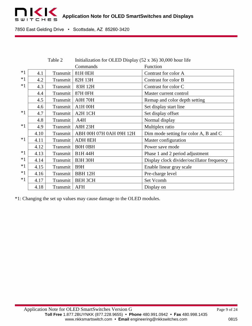
Table 2 Initialization for OLED Display (52 x 36) 30,000 hour life
Commands Function
*1 4.1 Transmit 81H 0EH Contrast for color A
*1 4.2 Transmit 82H 13H Contrast for color B
*1 4.3 Transmit 83H 12H Contrast for color C
4.4 Transmit 87H 0FH Master current control
4.5 Transmit A0H 70H Remap and color depth setting
4.6 Transmit A1H 00H Set display start line
*1 4.7 Transmit A2H 1CH Set display offset
4.8 Transmit A4H Normal display
*1 4.9 Transmit A8H 23H Multiplex ratio
4.10 Transmit ABH 00H 07H 0AH 09H 12H Dim mode setting for color A, B and C
*1 4.11 Transmit ADH 8EH Master configuration
4.12 Transmit B0H 0BH Power save mode
*1 4.13 Transmit B1H 44H Phase 1 and 2 period adjustment
*1 4.14 Transmit B3H 30H Display clock divider/oscillator frequency
*1 4.15 Transmit B9H Enable linear gray scale
*1 4.16 Transmit BBH 12H Pre-charge level
*1 4.17 Transmit BEH 3CH Set Vcomh
4.18 Transmit AFH Display on
*1: Changing the set up values may cause damage to the OLED modules.

Application Note for OLED SmartSwitches and Displays
7850 East Gelding Drive • Scottsdale, AZ 85260-3420
Application Note for OLED SmartSwitches Version G Page 10 of 24
Toll Free 1.877.2BUYNKK (877.228.9655) • Phone 480.991.0942 • Fax 480.998.1435 www.nkksmartswitch.com • Email [email protected] 0815
Table 3 Initialization for Frameless OLED switch (96 x 64) 50,000 hour life
Commands Function
*1 4.1 Transmit 81H 1CH Contrast for color A
*1 4.2 Transmit 82H 2EH Contrast for color B
*1 4.3 Transmit 83H 2CH Contrast for color C
*2 4.31 Transmit 8A 4F Second pre charge speed for color A
*2 4.32 Transmit 8B 74 Second pre charge speed for color B
*2 4.33 Transmit 8C 88 Second pre charge speed for color C
4.4 Transmit 87H 0FH Master current control
4.5 Transmit A0H 68H Remap and color depth setting
4.6 Transmit A1H 00H Set display start line
*1 4.7 Transmit A2H 00H Set display offset
4.8 Transmit A4H Normal display
*1 4.9 Transmit A8H 3FH Multiplex ratio
4.10 Transmit ABH 00H 0EH 17H 16H 12H Dim mode setting for color A, B and C
*1 4.11 Transmit ADH 8EH Master configuration
4.12 Transmit B0H 0BH Power save mode
*1 4.13 Transmit B1H 17H Phase 1 and 2 period adjustment
*1 4.14 Transmit B3H F0H Display clock divider/ oscillator frequency
*1 4.15 Transmit B9H Enable linear gray scale
*1 4.16 Transmit BBH 1DH Pre-charge level
*1 4.17 Transmit BEH 20H Set Vcomh
4.18 Transmit AFH Display on in normal mode
*1: Changing the set up values may cause damage to the OLED modules.
*2: All three commands must be transmitted in one session.
Upon finishing initialization, the OLED module displays the content of whatever is in the memory.
Application Note for OLED SmartSwitches and Displays
7850 East Gelding Drive • Scottsdale, AZ 85260-3420
Application Note for OLED SmartSwitches Version G Page 11 of 24
Toll Free 1.877.2BUYNKK (877.228.9655) • Phone 480.991.0942 • Fax 480.998.1435 www.nkksmartswitch.com • Email [email protected] 0815
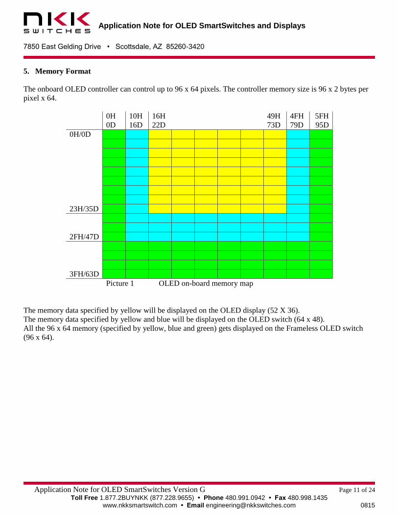
5. Memory Format
The onboard OLED controller can control up to 96 x 64 pixels. The controller memory size is 96 x 2 bytes per
pixel x 64.
0H 10H 16H 49H 4FH 5FH
0D 16D 22D 73D 79D 95D
0H/0D
23H/35D
2FH/47D
3FH/63D
Picture 1 OLED on-board memory map
The memory data specified by yellow will be displayed on the OLED display (52 X 36).
The memory data specified by yellow and blue will be displayed on the OLED switch (64 x 48).
All the 96 x 64 memory (specified by yellow, blue and green) gets displayed on the Frameless OLED switch
(96 x 64).

Application Note for OLED SmartSwitches and Displays
7850 East Gelding Drive • Scottsdale, AZ 85260-3420
Application Note for OLED SmartSwitches Version G Page 12 of 24
Toll Free 1.877.2BUYNKK (877.228.9655) • Phone 480.991.0942 • Fax 480.998.1435 www.nkksmartswitch.com • Email [email protected] 0815
6. Specifying a Memory Window for Downloading
A memory window is specified by a beginning and end column and a beginning and end row. These boundaries
are set by commands 15H and 75H.
The two bytes following the 15H command specify the beginning and end columns (Range 00H to 5FH) and the
cursor moves to the beginning column.
The two bytes following the 75H command specify the beginning and end rows. (Range 00H to 3FH) and the
cursor moves to the beginning row.
The boundaries of the memory window can be changed at any time to any size and location of the memory.
Table 5 shows the commands to specify the size and location of memory corresponding to the OLED switch
(64 x 48).
Table 6 shows the commands to specify the size and location of memory corresponding to the OLED display
(52 x 36).
Table 7 shows the commands to specify the size and location of memory corresponding to Frameless OLED
switch (96 x 64).
Table 5 Setting the columns and rows and putting the cursor at top left
OLED display (64 x 48)
Commands Function
Transmit 15H 10H 4FH Set the column range
Transmit 75H 00H 2FH Set the row range
Table 6 Setting the columns and rows and putting the cursor at top left
OLED display (52 x 36)
Commands Function
Transmit 15H 16H 49H Set the columns range
Transmit 75H 00H 23H Set the rows range
Table 7 Setting the columns and rows and putting the cursor at top left
Frameless OLED display (96 x 64)
Commands Function
Transmit 15H 00H 5FH Set the column range
Transmit 75H 00H 3FH Set the row range

Application Note for OLED SmartSwitches and Displays
7850 East Gelding Drive • Scottsdale, AZ 85260-3420
Application Note for OLED SmartSwitches Version G Page 13 of 24
Toll Free 1.877.2BUYNKK (877.228.9655) • Phone 480.991.0942 • Fax 480.998.1435 www.nkksmartswitch.com • Email [email protected] 0815
With the suggested initialization of tables 1, 2 and 3, the cursor starts at the upper left hand pixel of the
specified memory window. The cursor increments to the next pixel to the right after two bytes of data for a
pixel are received. After receiving data for the right most pixel of a row, the cursor moves to the left hand pixel
of the next row. Once the last row is completed, the cursor returns to left hand pixel of the first row. There are
other cursor movement option explained in section 12.
Any data transmitted when the D/C pin is high is considered as image data. The OLED onboard controller
continuously refreshes the OLED from the memory. Any changes to the memory will be displayed
immediately.

Application Note for OLED SmartSwitches and Displays
7850 East Gelding Drive • Scottsdale, AZ 85260-3420
Application Note for OLED SmartSwitches Version G Page 14 of 24
Toll Free 1.877.2BUYNKK (877.228.9655) • Phone 480.991.0942 • Fax 480.998.1435 www.nkksmartswitch.com • Email [email protected] 0815
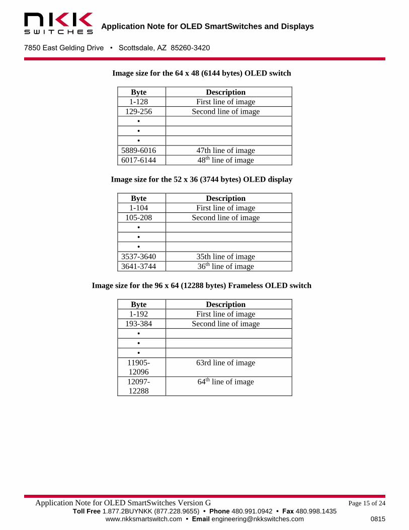
7. Pixels and Image Format
Each pixel requires two bytes in the 565 format as shown below:
It may be best to create the images in a computer as 24-bit bitmap (.bmp) images, which is standard, then
extract the 16 bits from the three bytes of the 24-bit bitmap. The Universal Communicator converts the three
bytes to two bytes as shown in the image below:
When resizing an image to fit the size of the OLED switch or display, consider compressing the image in
order to compensate for the fact that the pixels are not square. It is best to compress before resizing.
Vertical compression Horizontal compression
ISF15ACP4 96 x 54 75% None
ISC15ANP4 64 x 48 None 5%
ISC01P 52 x 36 5% None
B
7
B
6
B
5
B
4
B
3
G
2
G
1
G
0
G
7
G
6
G
5
R
4
R
3
R
2
R
1
R
0
Application Note for OLED SmartSwitches and Displays
7850 East Gelding Drive • Scottsdale, AZ 85260-3420
Application Note for OLED SmartSwitches Version G Page 15 of 24
Toll Free 1.877.2BUYNKK (877.228.9655) • Phone 480.991.0942 • Fax 480.998.1435 www.nkksmartswitch.com • Email [email protected] 0815
Image size for the 64 x 48 (6144 bytes) OLED switch
Byte Description
1-128 First line of image
129-256 Second line of image
•
•
•
5889-6016 47th line of image
6017-6144 48th line of image
Image size for the 52 x 36 (3744 bytes) OLED display
Byte Description
1-104 First line of image
105-208 Second line of image
•
•
•
3537-3640 35th line of image
3641-3744 36th line of image
Image size for the 96 x 64 (12288 bytes) Frameless OLED switch
Byte Description
1-192 First line of image
193-384 Second line of image
•
•
•
11905-
12096
63rd line of image
12097-
12288
64th line of image

Application Note for OLED SmartSwitches and Displays
7850 East Gelding Drive • Scottsdale, AZ 85260-3420
Application Note for OLED SmartSwitches Version G Page 16 of 24
Toll Free 1.877.2BUYNKK (877.228.9655) • Phone 480.991.0942 • Fax 480.998.1435 www.nkksmartswitch.com • Email [email protected] 0815
8. Display Commands Available
Display On/Off
The following three commands can be used at any time. They do not affect the content of the memory:
1 Transmit ACH Dim display
2 Transmit AEH Display off (sleep mode)
3 Transmit AFH Display on
Transmitting the AEH command turns the display off. Transmitting the AFH command turns the display on in
normal mode.
Transmitting the ACH command turns the display on in dim mode. The dim mode level corresponds to
initialization step 4.10. The last three bytes are the contrast for colors A, B and C. The values can not exceed the
maximum level for each color of initialization as noted in steps 4.1, 4.2 and 4.3, respectively.
Powering Down Sequences
The following procedure is recommended to be followed for turning the OLED switch or display off:
1. Transmit the command to turn the OLED display off.
Transmit AEH Display off
2. Disable the VCC.
3. Turn off the VDD power.

Application Note for OLED SmartSwitches and Displays
7850 East Gelding Drive • Scottsdale, AZ 85260-3420
Application Note for OLED SmartSwitches Version G Page 17 of 24
Toll Free 1.877.2BUYNKK (877.228.9655) • Phone 480.991.0942 • Fax 480.998.1435 www.nkksmartswitch.com • Email [email protected] 0815
9. Additional Commands Available
No Operation
Transmit E3H NOP
Transmit BCH NOP
Transmit BDH NOP
Display Mode
These are one byte commands. They do not affect memory data.
Transmit A4H Normal operation
Transmit A5H
All pixels on at the highest
brightness
Transmit A6H All pixels on at lowest brightness
Transmit A7H Inverse display
Command A4H is for normal operation. Commands A5H/A6H forces all pixels to their highest/lowest intensity
regardless of the contents of the memory. The A7H command causes the complement of the pixels’ data from
memory to be displayed.
Master Current Control
Transmit 87H 0FH Master current control
This command should be used while the display is off (after command AEH).
There are 16 steps for the current level (00H to 0FH). 0FH is the maximum brightness and 00H is the
minimum brightness. The OLED life of 30,000/50,000 hours is based on 0FH brightness. The dimmer
the OLEDs are while in use, the longer their life expectancy.

Application Note for OLED SmartSwitches and Displays
7850 East Gelding Drive • Scottsdale, AZ 85260-3420
Application Note for OLED SmartSwitches Version G Page 18 of 24
Toll Free 1.877.2BUYNKK (877.228.9655) • Phone 480.991.0942 • Fax 480.998.1435 www.nkksmartswitch.com • Email [email protected] 0815
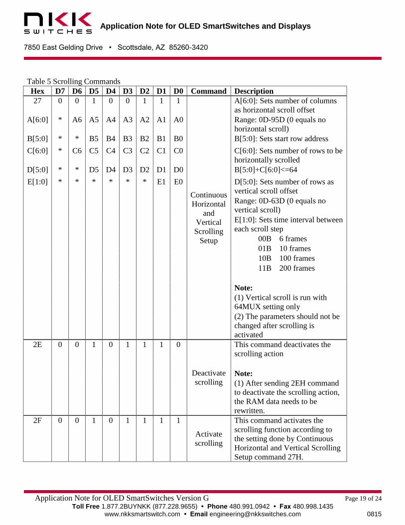
10. Scrolling (Screensaver)
Command 27H is used to set up the parameter for scrolling. This command can only be transmitted during
initialization or when the display is off and scrolling is deactivated (commands AEH and 2EH). The sequence
of use is as follows: First, turn off the display and deactivate scrolling and send data for an image. Second, send
the command 27H. Finally, turn the display on and activate the scrolling (commands AFH and 2FH).
Command 27H has five bytes of data; A, B, C, D and E.
Byte A sets the number of columns shifted horizontally to the right each time. For example, the value
01H will make the image appear to be shifting from the right to left. The value 5FH will make the image
appear to be shifting from the left to right. Byte A should not be set to 00H or it will deactivate the
scrolling for the rest of the session. Scrolling cannot be reactivated. Therefore, the Byte A value should
be set between 01H and 5FH.
Byte B sets the offset or starting row.
Byte C sets the number of rows that get shifted horizontally.
Byte D sets the number of rows that are vertically shifted up each time. For example the value 01H will
make the image appear to be shifting from the bottom to top. The value 3FH will make the image appear
to be shifting from the top to bottom. A zero value for byte D indicates no vertical shift.
Byte E sets the interval between each shift.
The horizontal speed of scrolling is determined by the value of bytes A and E.
The vertical speed of scrolling is determined by the value of bytes D and E.
The portion of the image that is horizontally shifted is determined by the values of bytes B and C.
For the horizontal scroll, rows selected will shift using the 96 columns.
For vertical scroll, all 96 columns will be shifted using all 64 rows.
After deactivation, the position of the contents of the memory has been changed due to the shifts. To
restore the original image, the image data should be downloaded again. Refer to Table 5.
Application Note for OLED SmartSwitches and Displays
7850 East Gelding Drive • Scottsdale, AZ 85260-3420
Application Note for OLED SmartSwitches Version G Page 19 of 24
Toll Free 1.877.2BUYNKK (877.228.9655) • Phone 480.991.0942 • Fax 480.998.1435 www.nkksmartswitch.com • Email [email protected] 0815
Table 5 Scrolling Commands
Hex D7 D6 D5 D4 D3 D2 D1 D0 Command Description
27 0 0 1 0 0 1 1 1
Continuous
Horizontal
and
Vertical
Scrolling
Setup
A[6:0]: Sets number of columns
as horizontal scroll offset
A[6:0] * A6 A5 A4 A3 A2 A1 A0 Range: 0D-95D (0 equals no
horizontal scroll)
B[5:0] * * B5 B4 B3 B2 B1 B0 B[5:0]: Sets start row address
C[6:0] * C6 C5 C4 C3 C2 C1 C0 C[6:0]: Sets number of rows to be
horizontally scrolled
D[5:0] * * D5 D4 D3 D2 D1 D0 B[5:0]+C[6:0]<=64
E[1:0] * * * * * * E1 E0 D[5:0]: Sets number of rows as
vertical scroll offset
Range: 0D-63D (0 equals no
vertical scroll)
E[1:0]: Sets time interval between
each scroll step
00B 6 frames
01B 10 frames
10B 100 frames
11B 200 frames
Note:
(1) Vertical scroll is run with
64MUX setting only
(2) The parameters should not be
changed after scrolling is
activated
2E 0 0 1 0 1 1 1 0
Deactivate
scrolling
This command deactivates the
scrolling action
Note:
(1) After sending 2EH command
to deactivate the scrolling action,
the RAM data needs to be
rewritten.
2F 0 0 1 0 1 1 1 1
Activate
scrolling
This command activates the
scrolling function according to
the setting done by Continuous
Horizontal and Vertical Scrolling
Setup command 27H.

Application Note for OLED SmartSwitches and Displays
7850 East Gelding Drive • Scottsdale, AZ 85260-3420
Application Note for OLED SmartSwitches Version G Page 20 of 24
Toll Free 1.877.2BUYNKK (877.228.9655) • Phone 480.991.0942 • Fax 480.998.1435 www.nkksmartswitch.com • Email [email protected] 0815
11. Graphic Commands
Table 6 and table 7 have the graphic commands. Please note the command 26H is the set up which effect the
operation of commands 22H and 23H. Note: Graphic commands modify the content of memory.
Table 6 Graphic Commands
Hex D7 D6 D5 D4 D3 D2 D1 D0 Command Description
21 0 0 1 0 0 0 0 1
Draw Line
A[6:0]: Column address of start
A[6:0] * A6 A5 A4 A3 A2 A1 A0 B[5:0]: Row address of start
B[5:0] * * B5 B4 B3 B2 B1 B0 C[6:0]: Column address of end
C[6:0] * C6 C5 C4 C3 C2 C1 C0 D[5:0]: Row address of end
D[5:0] * * D5 D4 D3 D2 D1 D0 E[5:1]: Color C of the line
E[5:1] * * E5 E4 E3 E2 E1 * F[5:0]: Color B of the line
F[5:0] * * F5 F4 F3 F2 F1 F0 G[5:1]: Color A of the line
G[5:1] * * G5 G4 G3 G2 G1 *
24 0 0 1 0 0 1 0 0
Dim
Window
A[6:0]: Column address of start
A[6:0] * A6 A5 A4 A3 A2 A1 A0 B[5:0]: Row address of start
B[5:0] * * B5 B4 B3 B2 B1 B0 C[6:0]: Column address of end
C[6:0] * C6 C5 C4 C3 C2 C1 C0 D[5:0]: Row address of end
D[5:0] * * D5 D4 D3 D2 D1 D0 The effect of dim window:
GS15~GS0 no change
GS19~GS16 become GS4
GS23~GS20 become GS5
…
GS62~GS60 become GS15
25 0 0 1 0 0 1 0 1
Clear
Window
A[6:0]: Column address of start
A[6:0] * A6 A5 A4 A3 A2 A1 A0 B[5:0]: Row address of start
B[5:0] * * B5 B4 B3 B2 B1 B0 C[6:0]: Column address of end
C[6:0] * C6 C5 C4 C3 C2 C1 C0 D[5:0]: Row address of end
D[5:0] * * D5 D4 D3 D2 D1 D0

Application Note for OLED SmartSwitches and Displays
7850 East Gelding Drive • Scottsdale, AZ 85260-3420
Application Note for OLED SmartSwitches Version G Page 21 of 24
Toll Free 1.877.2BUYNKK (877.228.9655) • Phone 480.991.0942 • Fax 480.998.1435 www.nkksmartswitch.com • Email [email protected] 0815
Table 7 Graphic Commands and Set Up
Hex D7 D6 D5 D4 D3 D2 D1 D0 Command Description
22 0 0 1 0 0 0 1 0
Drawing
Rectangle
A[6:0]: Column address of start
A[6:0] * A6 A5 A4 A3 A2 A1 A0 B[5:0]: Row address of start
B[5:0] * * B5 B4 B3 B2 B1 B0 C[6:0]: Column address of end
C[6:0] * C6 C5 C4 C3 C2 C1 C0 D[5:0]: Row address of end
D[5:0] * * D5 D4 D3 D2 D1 D0 E[5:1]: Color C of the line
E[5:1] * * E5 E4 E3 E2 E1 * F[5:0]: Color B of the line
F[5:0] * * F5 F4 F3 F2 F1 F0 G[5:1]: Color A of the line
G[5:1] * * G5 G4 G3 G2 G1 * H[5:1]: Color C of the fill area
H[5:1] * * H5 H4 H3 H2 H1 * I [5:0]: Color B of the fill area
I[5:0] * * I5 I4 I3 I2 I1 I0 J[5:1]: Color A of the fill area
J[5:1] * * J5 J4 J3 J2 J1 *
23 0 0 1 0 0 0 1 1
Copy
A[6:0]: Column address of start
A[6:0] * A6 A5 A4 A3 A2 A1 A0 B[5:0]: Row address of start
B[5:0] * * B5 B4 B3 B2 B1 B0 C[6:0]: Column address of end
C[6:0] * C6 C5 C4 C3 C2 C1 C0 D[5:0]: Row address of end
D[5:0] * * D5 D4 D3 D2 D1 D0 E[6:0]: Column address of new
start
E[6:0] * E6 E5 E4 E3 E2 E1 E0 F[5:0]: Row address of new start
F[5:0] * * F5 F4 F3 F2 F1 F0
26 0 0 1 0 0 1 1 0
Fill Enable
/ Disable
A0 0 : Disable fill for draw
rectangle command (RESET)
A[4:0] * * * A4 0 0 0 A0 1 : Enable fill for draw
rectangle command
A[3:1] 000: Reserved values
A4 0 : Disable reverse copy
(RESET)
1 : Enable reverse during
copy command

Application Note for OLED SmartSwitches and Displays
7850 East Gelding Drive • Scottsdale, AZ 85260-3420
Application Note for OLED SmartSwitches Version G Page 22 of 24
Toll Free 1.877.2BUYNKK (877.228.9655) • Phone 480.991.0942 • Fax 480.998.1435 www.nkksmartswitch.com • Email [email protected] 0815
12. Initialization Options
This command is the step 4.5 of initialization. There are many options for format of the image data as well as
selecting the 256 color instead of 65K. For 256 colors each pixels has one byte of data in the format of
BBBGGGRR. However the on-board controller translates it to two bytes upon receiving the byte.
Hex D7 D6 D5 D4 D3 D2 D1 D0 Command Description
A0 1 0 1 0 0 0 0 0
Remap
and color /
Depth
setting
A[0]= 0 : Horizontal address
increment
A[7:0] A7 A6 A5 A4 A3 A2 A1 A0 A[0]=1 : Vertical address
increment
A[1]=0 : RAM column 0 to 95
maps to pin seg 0 to 95
A[1]=1 : RAM column 0 to 95
maps to pin seg 95 to 0
A[2]=0 : Normal order
SA,SB,SC (eg BGR)
A[2]=1 : Reverse order
SC,SB,SA (eg RGB)
A[3]=0 : Disable left-right
swapping on COM
A[3]=1 : Set left-right swapping
on COM
A[4]=0 Row 0 to Row (n-1)
A[4]=1 Row (n-1) to Row 0
A[5]=1 must be set to 1
A[7,6]=00 : 256 color
A[7,6]=01 : 65k color
A[7,6]=10 : reserved
A[7,6]=11 : reserved

Application Note for OLED SmartSwitches and Displays
7850 East Gelding Drive • Scottsdale, AZ 85260-3420
Application Note for OLED SmartSwitches Version G Page 23 of 24
Toll Free 1.877.2BUYNKK (877.228.9655) • Phone 480.991.0942 • Fax 480.998.1435 www.nkksmartswitch.com • Email [email protected] 0815
13. Sample Schematic for a Multi-switch Controller
Below is a sample schematic to control two OLED modules. With the theoretical maximum clock frequency of
6.6 MHz, 134 images per second can be transmitted via SPI. However, realistically, 84 images per second is
possible. There are 6144 bytes for each image in the 65k color mode. One image takes 6144 bytes * 8 bits/byte
= 49152 bits. Dividing the SPI frequency by 49152 provides the maximum number of images that can be
transmitted per second. The preceding calculation does not consider overhead and data retrieving time.
Illustration 1: Sample schematic for control of two OLED modules
GND
ENABLE
Vin
Vout
CHARGE PUMP
SCK
MISO
P2
MOSI
P1
P3
P4
P5
Microcontroller
Voled
SCK
D/C
RES
CS
SDI
OLED1
Voled
SCK
D/C
RES
CS
SDI
OLED2
25 OHM
25 OHM
25 OHM
25 OHM
R110k

Application Note for OLED SmartSwitches and Displays
7850 East Gelding Drive • Scottsdale, AZ 85260-3420
Application Note for OLED SmartSwitches Version G Page 24 of 24
Toll Free 1.877.2BUYNKK (877.228.9655) • Phone 480.991.0942 • Fax 480.998.1435 www.nkksmartswitch.com • Email [email protected] 0815
14. Frequently Asked Questions
How many different colors can each pixel display?
65,536 different colors. OLEDs have the most vivid and sharp display among all the technologies.
Is the OLED SmartSwitch/Display capable of displaying movies?
Yes. The OLED response time is 0.2 ms, which is the best among all the display technologies. The bottle neck
is normally the communication speed. Over 100 frames per second (60 fps for the Frameless OLED) of data can
be transmitted to the OLED SmartSwitch or display. Most videos are 24 to 30 frames per second.
Can the OLED SmartSwitch/Display capable of displaying live video?
Yes. However, the controller has to be fast enough to resize and transmit the data in the right format to the
OLED SmartSwitch/Display.
What is aging?
Aging for the OLED refers to the reduction in brightness over time. Specifically, the OLED life is defined as
the time it takes for the brightness to reach half the original state. Since the OLED is intended to display movies
or frequently changing images, it is assumed that each pixels will be on the equivalent of 40% of the time at full
brightness.
How does aging affect the colors?
When displaying movies, the OLED colors pixels age proportionally and the combined colors stay relatively
consistent. However when a still image or text is used for an extended period of time, the pixels used for the
image/text will get dimmer than surrounding pixels that have not been used. For example, if a blue color is used
in one area most the time, when white is displayed in that area, the white will have a tint of yellow. The yellow
is because red and green is now stronger than the blue. However, by properly designing the image colors and by
anticipating the amount of time they will be displayed, this problem can be avoided.
Does the power up/down sequence have to be followed?
Yes. The power up sequence must be observed. If VCC powers the circuit before VDD is activated, the circuit
could latch and damage the OLED.
For the power down sequence, VCC cannot be present after VDD is off. Simultaneous turn off is possible as long
as VCC is examined to confirm that it does not have too much capacitance charge after turn off.
Are subassemblies of SmartSwitches available?
Yes. NKK Switches has many development kits and also supports custom designs.
Is NKK Switches planning to develop other sizes of the OLED SmartSwitch?
NKK Switches continuously improves existing product as well as develops new products. Customer feedback is
considered when deciding what new products to develop. Feedback and/or application requirements is
welcomed.