Application Notes CAN FMS/J1939 CAN OBD-II · 4 DYNAMIC PROTOCOL ... Locatng your OBD-II connector...
21
This document is available at http://www.FALCOM.de/. Applicaon Notes CAN FMS/J1939 CAN OBD-II Version: 1.0.4; Created: Thursday 15 March 2018
Transcript of Application Notes CAN FMS/J1939 CAN OBD-II · 4 DYNAMIC PROTOCOL ... Locatng your OBD-II connector...
This document is available at http://www.FALCOM.de/.
Application Notes
CAN FMS/J1939
CAN OBD-II
Version: 1.0.4; Created: Thursday 15 March 2018
HOW TO GET CAN-BUS INFORMATION VIA FMS OR OBD-II INTERFACE VERSION 1.0.4
Version history:
This table provides a summary of the document revisions.
Version Author Changes Modifed
1.0.4 F. Beqiri - Updated secton 2.4.1 and removed secton 2.4.2. 15/03/2018
1.0.3 F. Beqiri - Added new FMS variable (dynamic entries) - FMS_HR_TOTAL_FUEL_USED 29/08/2016
1.0.2 F. Beqiri - Added new FMS variable (dynamic entries) 29/10/2014
1.0.1 F. Beqiri - Extended chapter 1 and added chapter 2 07/08/2012
1.0.0 F. Beqiri - Inital version 01/03/2012
This confdental document is a property of FALCOM and may not be copied or circulated without previous permission.
Page 2 of 21
HOW TO GET CAN-BUS INFORMATION VIA FMS OR OBD-II INTERFACE VERSION 1.0.4
Table of contents
1 INTRODUCTION ....................................................................................................... 5
2 REQUIREMENTS FOR READING DATA ON THE VEHICLE BUS VIA OBD-II/FMS/J1939 . 6
2.1 FALCOM AVL devices with CAN-Bus opton .......................................................................... 6
2.2 Installing the SIM card .......................................................................................................... 7
2.3 Connectng AVL device to the vehicle bus ............................................................................ 7
2.4 Confguring devices for reading vehicle informaton (examples) .......................................... 8 2.4.1 How to fnd out, which OBD-II PIDs are supported by a vehicle? ................................................... 10
3 COMMANDS AND CONFIGURATION SYNTAX ......................................................... 11
3.1 Confgure and actvate OBD-II, FMS or J1939 interface ...................................................... 11
3.2 Firmware confguraton ...................................................................................................... 12
3.3 OBDII, FMS, J1939 Events ................................................................................................... 14 3.3.1 OBDII event ..................................................................................................................................... 14 3.3.2 FMS event ........................................................................................................................................ 14 3.3.3 J1939 event ..................................................................................................................................... 15
4 DYNAMIC PROTOCOL ............................................................................................. 16
4.1 Dynamic protocols for FMS/J1939 ...................................................................................... 16
4.2 Dynamic protocol for OBD-II ............................................................................................... 21
This confdental document is a property of FALCOM and may not be copied or circulated without previous permission.
Page 3 of 21
HOW TO GET CAN-BUS INFORMATION VIA FMS OR OBD-II INTERFACE VERSION 1.0.4
Cautons
Informaton furnished herein by FALCOM is believed to be accurate and reliable. However, noresponsibility is assumed for its use. Please, read carefully the safety precautons.If you have any technical questons regarding this document or the product described in it, pleasecontact your vendor.General informaton about FALCOM and its range of products are available at the following Internetaddress: http://www.falcom.de/
Trademarks
Some mentoned products are registered trademarks of their respectve companies.
Copyright
This document is copyrighted by FALCOM GmbH with all rights reserved. No part of this documentatonmay be produced in any form without the prior written permission of FALCOM GmbH.
FALCOM GmbH.
The manufacture assumes no liability for any errors or discrepancies that may have occurred inpreparaton of this document.
Note
Specifcatons and informaton given in this document are subject to change by FALCOM without notce.
This confdental document is a property of FALCOM and may not be copied or circulated without previous permission.
Page 4 of 21
HOW TO GET CAN-BUS INFORMATION VIA FMS OR OBD-II INTERFACE VERSION 1.0.4
1 INTRODUCTION
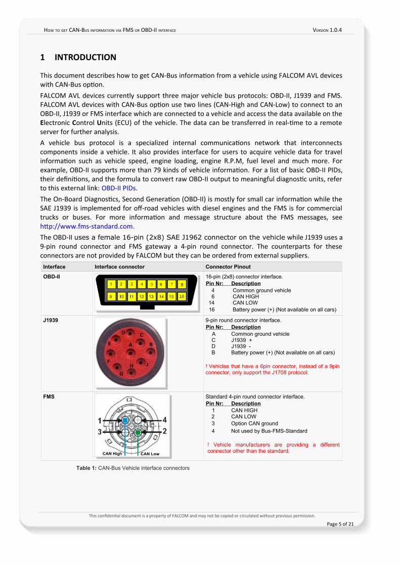
This document describes how to get CAN-Bus informaton from a vehicle using FALCOM AVL deviceswith CAN-Bus opton. FALCOM AVL devices currently support three major vehicle bus protocols: OBD-II, J1939 and FMS.FALCOM AVL devices with CAN-Bus opton use two lines (CAN-High and CAN-Low) to connect to anOBD-II, J1939 or FMS interface which are connected to a vehicle and access the data available on theElectronic Control Units (ECU) of the vehicle. The data can be transferred in real-tme to a remoteserver for further analysis.A vehicle bus protocol is a specialized internal communicatons network that interconnectscomponents inside a vehicle. It also provides interface for users to acquire vehicle data for travelinformaton such as vehicle speed, engine loading, engine R.P.M, fuel level and much more. Forexample, OBD-II supports more than 79 kinds of vehicle informaton. For a list of basic OBD-II PIDs,their defnitons, and the formula to convert raw OBD-II output to meaningful diagnostc units, referto this external link: OBD-II PIDs.The On-Board Diagnostcs, Second Generaton (OBD-II) is mostly for small car informaton while theSAE J1939 is implemented for of-road vehicles with diesel engines and the FMS is for commercialtrucks or buses. For more informaton and message structure about the FMS messages, seehttp://www.fms-standard.com.The OBD-II uses a female 16-pin (2x8) SAE J1962 connector on the vehicle while J1939 uses a9-pin round connector and FMS gateway a 4-pin round connector. The counterparts for theseconnectors are not provided by FALCOM but they can be ordered from external suppliers.
Interface Interface connector Connector Pinout
OBD-II 16-pin (2x8) connector interface.Pin Nr: Description
4 Common ground vehicle 6 CAN HIGH
14 CAN LOW 16 Battery power (+) (Not available on all cars)
J1939 9-pin round connector interface.Pin Nr: Description
A Common ground vehicle C J1939 + D J1939 - B Battery power (+) (Not available on all cars)
! Vehicles that have a 6pin connector, instead of a 9pinconnector, only support the J1708 protocol.
FMS Standard 4-pin round connector interface. Pin Nr: Description
1 CAN HIGH 2 CAN LOW 3 Option CAN ground
4 Not used by Bus-FMS-Standard
! Vehicle manufacturers are providing a differentconnector other than the standard.
Table 1: CAN-Bus Vehicle interface connectors
This confdental document is a property of FALCOM and may not be copied or circulated without previous permission.
Page 5 of 21
HOW TO GET CAN-BUS INFORMATION VIA FMS OR OBD-II INTERFACE VERSION 1.0.4
2 REQUIREMENTS FOR READING DATA ON THE VEHICLE BUS VIA OBD-II/FMS/J1939
To read data from a vehicle bus you’ll need:
1. A Falcom AVL device with CAN-Bus opton (e.g. STEPPIII-UX-CH-B1),
2. A SIM card supportng GPRS for transmitng vehicle data over GPRS to a server,
3. Device confguraton setngs for getng informaton from the vehicle bus,
4. Connectng AVL devices to the vehicle bus with the help of vehicle installaton cable,
5. Vehicle supportng SAE J1939, OBD-II or FMS,
6. Power supply from vehicle battery.
2.1 FALCOM AVL devices with CAN-Bus option
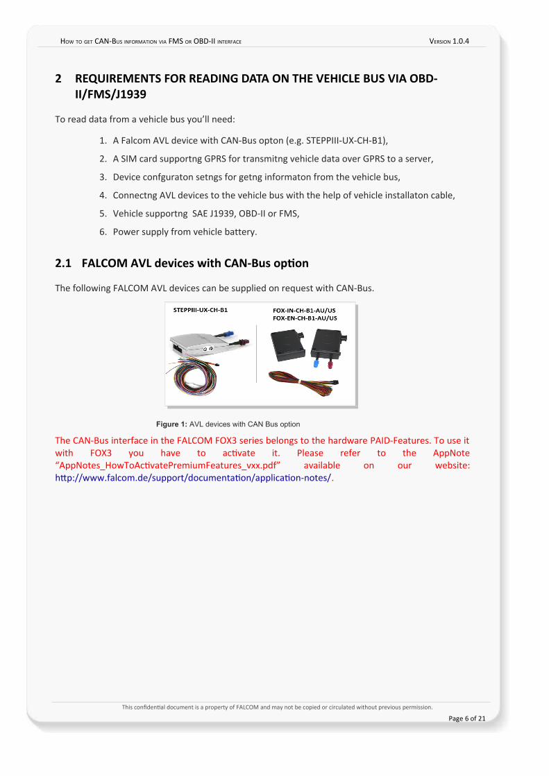
The following FALCOM AVL devices can be supplied on request with CAN-Bus.
Figure 1: AVL devices with CAN Bus option
The CAN-Bus interface in the FALCOM FOX3 series belongs to the hardware PAID-Features. To use itwith FOX3 you have to actvate it. Please refer to the AppNote“AppNotes_HowToActvatePremiumFeatures_vxx.pdf” available on our website:http://www.falcom.de/support/documentaton/applicaton-notes/.
This confdental document is a property of FALCOM and may not be copied or circulated without previous permission.
Page 6 of 21
HOW TO GET CAN-BUS INFORMATION VIA FMS OR OBD-II INTERFACE VERSION 1.0.4
2.2 Installing the SIM card
Please refer to the hardware manual of the device you are using to install the SIM card.
2.3 Connecting AVL device to the vehicle bus
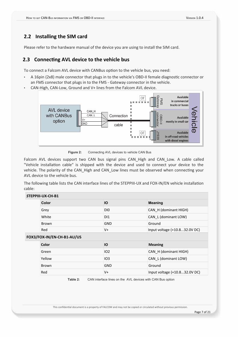
To connect a Falcom AVL device with CANBus opton to the vehicle bus, you need:• A 16pin (2x8) male connector that plugs in to the vehicle's OBD-II female diagnostc connector or
an FMS connector that plugs in to the FMS - Gateway connector in the vehicle.• CAN-High, CAN-Low, Ground and V+ lines from the Falcom AVL device.
Figure 2: Connecting AVL devices to vehicle CAN Bus
Falcom AVL devices support two CAN bus signal pins CAN_High and CAN_Low. A cable called"Vehicle installaton cable" is shipped with the device and used to connect your device to thevehicle. The polarity of the CAN_High and CAN_Low lines must be observed when connectng yourAVL device to the vehicle bus.
The following table lists the CAN interface lines of the STEPPIII-UX and FOX-IN/EN vehicle installatoncable:
STEPPIII-UX-CH-B1
Color IO Meaning
Grey DI0 CAN_H (dominant HIGH)
White DI1 CAN_L (dominant LOW)
Brown GND Ground
Red V+ Input voltage (+10.8...32.0V DC)
FOX3/FOX-IN/EN-CH-B1-AU/US
Color IO Meaning
Green IO2 CAN_H (dominant HIGH)
Yellow IO3 CAN_L (dominant LOW)
Brown GND Ground
Red V+ Input voltage (+10.8...32.0V DC)
Table 2: CAN interface lines on the AVL devices with CAN Bus option
This confdental document is a property of FALCOM and may not be copied or circulated without previous permission.
Page 7 of 21
HOW TO GET CAN-BUS INFORMATION VIA FMS OR OBD-II INTERFACE VERSION 1.0.4
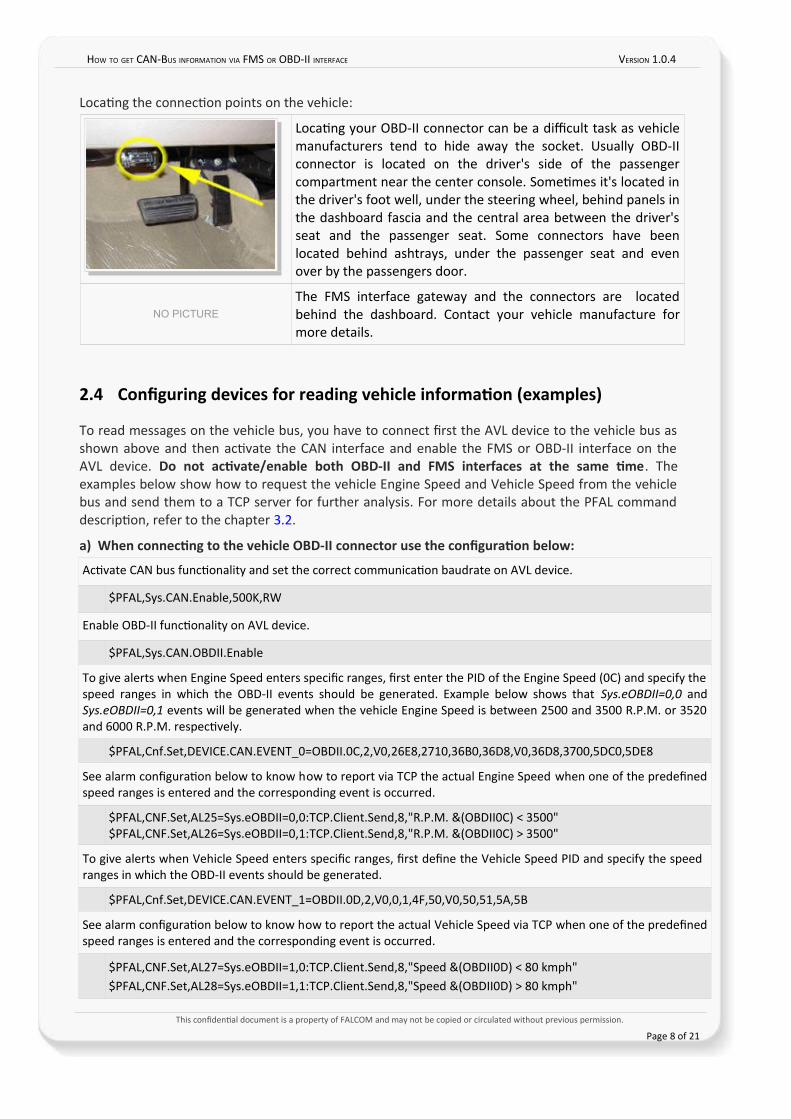
Locatng the connecton points on the vehicle:
Locatng your OBD-II connector can be a difcult task as vehiclemanufacturers tend to hide away the socket. Usually OBD-IIconnector is located on the driver's side of the passengercompartment near the center console. Sometmes it's located inthe driver's foot well, under the steering wheel, behind panels inthe dashboard fascia and the central area between the driver'sseat and the passenger seat. Some connectors have beenlocated behind ashtrays, under the passenger seat and evenover by the passengers door.
NO PICTURE
The FMS interface gateway and the connectors are locatedbehind the dashboard. Contact your vehicle manufacture formore details.
2.4 Confguring devices for reading vehicle information (examplesn
To read messages on the vehicle bus, you have to connect frst the AVL device to the vehicle bus asshown above and then actvate the CAN interface and enable the FMS or OBD-II interface on theAVL device. Do not activate/enable both OBD-II and FMS interfaces at the same time. Theexamples below show how to request the vehicle Engine Speed and Vehicle Speed from the vehiclebus and send them to a TCP server for further analysis. For more details about the PFAL commanddescripton, refer to the chapter 3.2.
an When connecting to the vehicle OBD-II connector use the confguration below:
Actvate CAN bus functonality and set the correct communicaton baudrate on AVL device.
$PFAL,Sys.CAN.Enable,500K,RW
Enable OBD-II functonality on AVL device.
$PFAL,Sys.CAN.OBDII.Enable
To give alerts when Engine Speed enters specifc ranges, frst enter the PID of the Engine Speed (0C) and specify thespeed ranges in which the OBD-II events should be generated. Example below shows that Sys.eOBDII=0,0 andSys.eOBDII=0,1 events will be generated when the vehicle Engine Speed is between 2500 and 3500 R.P.M. or 3520and 6000 R.P.M. respectvely.
$PFAL,Cnf.Set,DEVICE.CAN.EVENT_0=OBDII.0C,2,V0,26E8,2710,36B0,36D8,V0,36D8,3700,5DC0,5DE8
See alarm confguraton below to know how to report via TCP the actual Engine Speed when one of the predefnedspeed ranges is entered and the corresponding event is occurred.
$PFAL,CNF.Set,AL25=Sys.eOBDII=0,0:TCP.Client.Send,8,"R.P.M. &(OBDII0C) < 3500"$PFAL,CNF.Set,AL26=Sys.eOBDII=0,1:TCP.Client.Send,8,"R.P.M. &(OBDII0C) > 3500"
To give alerts when Vehicle Speed enters specifc ranges, frst defne the Vehicle Speed PID and specify the speedranges in which the OBD-II events should be generated.
$PFAL,Cnf.Set,DEVICE.CAN.EVENT_1=OBDII.0D,2,V0,0,1,4F,50,V0,50,51,5A,5B
See alarm confguraton below to know how to report the actual Vehicle Speed via TCP when one of the predefnedspeed ranges is entered and the corresponding event is occurred.
$PFAL,CNF.Set,AL27=Sys.eOBDII=1,0:TCP.Client.Send,8,"Speed &(OBDII0D) < 80 kmph"$PFAL,CNF.Set,AL28=Sys.eOBDII=1,1:TCP.Client.Send,8,"Speed &(OBDII0D) > 80 kmph"
This confdental document is a property of FALCOM and may not be copied or circulated without previous permission.
Page 8 of 21
HOW TO GET CAN-BUS INFORMATION VIA FMS OR OBD-II INTERFACE VERSION 1.0.4
bn When connecting to the vehicle FMS-Gateway or J1939 connector use the confguration below:
Actvate CAN Bus and set the communicaton baudrate on AVL device.
$PFAL,Sys.CAN.Enable,250K,RO
Enable FMS functonality on AVL device and restart the AVL device.
$PFAL,Sys.CAN.FMS.Enable
To give alerts when Engine Speed enters specifc ranges, frst enter the predefned FMS parameter of the EngineSpeed (FMS.ENGINE_SPEED) and specify the speed ranges in which the FMS events should be generated. Examplebelow shows that Sys.eFMS=0,0 and Sys.eFMS=0,1 events will be generated when the vehicle Engine Speed isbetween 2500 and 3500 R.P.M. or 3520 and 6000 R.P.M. respectvely.
$PFAL,Cnf.Set,DEVICE.CAN.EVENT_0=FMS.ENGINE_SPEED,2,V0,26E8,2710,36B0,36D8,V0,36D8,3700,5DC0,5DE8
See alarm confguraton below to know how to report via TCP the actual Engine Speed when one of the predefnedspeed ranges is entered and the corresponding event is occurred.
$PFAL,CNF.Set,AL25=Sys.eFMS=0,0:TCP.Client.Send,8,"R.P.M. &(FMS.ENGINE_SPEED) < 3500"$PFAL,CNF.Set,AL26=Sys.eFMS=0,1:TCP.Client.Send,8,"R.P.M. &(FMS.ENGINE_SPEED) > 3520"
To give alerts when Vehicle Speed enters specifc ranges, frst defne the FMS parameter of the Vehicle Speed andspecify the speed ranges in which the FMS events should be generated.
$PFAL,Cnf.Set,DEVICE.CAN.EVENT_1=FMS.SPEED_WB_KMPH,2,V0,0,1,4F,50,V0,50,51,5A,5B
See alarm confguraton below to know how to report the actual Vehicle Speed via TCP when one of the predefnedspeed ranges is entered and the corresponding event is occurred.
$PFAL,CNF.Set,AL27=Sys.eFMS=1,0:TCP.Client.Send,8,"Speed &(FMS.SPEED_WB_KMPH) < 80 kmph"$PFAL,CNF.Set,AL28=Sys.eFMS=1,1:TCP.Client.Send,8,"Speed &(FMS.SPEED_WB_KMPH) > 80 kmph"
To give alerts when Brake Pedal is pressed or released, frst defne the FMS parameter of Brake Switch and specifythe states when the FMS Brake events should be generated.
$PFAL,Cnf.Set,DEVICE.CAN.EVENT_2=FMS.BRAKE_SWITCH,2,BH0,BL0
See alarm confguraton below to know how to report via TCP the sate of Brake Switch when it is pressed orreleased.
$PFAL,CNF.Set,AL29=Sys.eFMS=2,0:TCP.Client.Send,8,"BRAKE: &(FMS.BRAKE_SWITCH)"$PFAL,CNF.Set,AL30=Sys.eFMS=2,1:TCP.Client.Send,8,"BRAKE: &(FMS.BRAKE_SWITCH)"
This confdental document is a property of FALCOM and may not be copied or circulated without previous permission.
Page 9 of 21
HOW TO GET CAN-BUS INFORMATION VIA FMS OR OBD-II INTERFACE VERSION 1.0.4
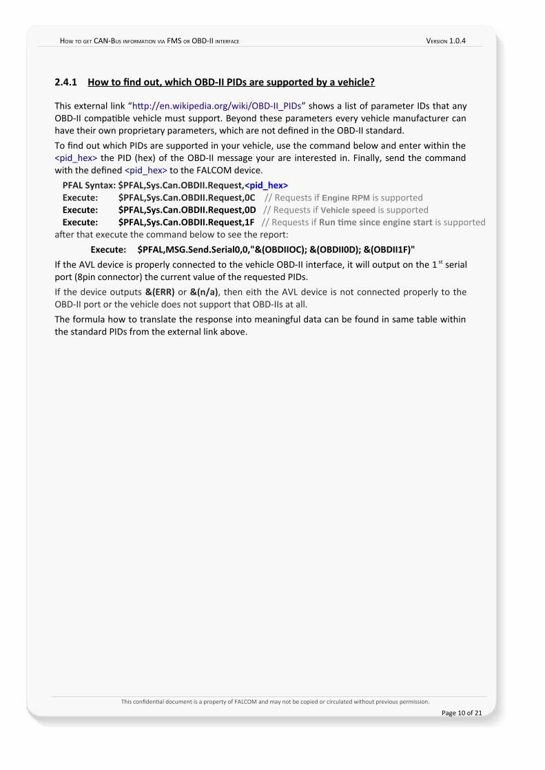
2.4.1 How to fnd out, which OBD-II PIDs are supported by a vehicle?
This external link “http://en.wikipedia.org/wiki/OBD-II_PIDs” shows a list of parameter IDs that anyOBD-II compatble vehicle must support. Beyond these parameters every vehicle manufacturer canhave their own proprietary parameters, which are not defned in the OBD-II standard.To fnd out which PIDs are supported in your vehicle, use the command below and enter within the<pid_hex> the PID (hex) of the OBD-II message your are interested in. Finally, send the commandwith the defned <pid_hex> to the FALCOM device.
PFAL Syntax: $PFAL,Sys.Can.OBDII.Request,<pid_hex>Execute: $PFAL,Sys.Can.OBDII.Request,0C // Requests if Engine RPM is supportedExecute: $PFAL,Sys.Can.OBDII.Request,0D // Requests if Vehicle speed is supportedExecute: $PFAL,Sys.Can.OBDII.Request,1F // Requests if Run time since engine start is supported
afer that execute the command below to see the report:Execute: $PFAL,MSG.Send.Serial0,0,"&(OBDIIOCn; &(OBDII0Dn; &(OBDII1Fn"
If the AVL device is properly connected to the vehicle OBD-II interface, it will output on the 1 st serialport (8pin connector) the current value of the requested PIDs. If the device outputs &(ERRn or &(n/an, then eith the AVL device is not connected properly to theOBD-II port or the vehicle does not support that OBD-IIs at all.The formula how to translate the response into meaningful data can be found in same table withinthe standard PIDs from the external link above.
This confdental document is a property of FALCOM and may not be copied or circulated without previous permission.
Page 10 of 21
HOW TO GET CAN-BUS INFORMATION VIA FMS OR OBD-II INTERFACE VERSION 1.0.4
3 COMMANDS AND CONFIGURATION SYNTAX
3.1 Confgure and activate OBD-II, FMS or J1939 interface
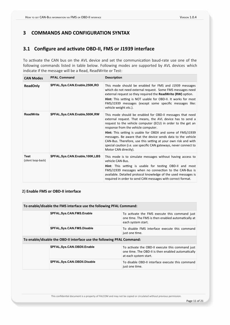
To actvate the CAN bus on the AVL device and set the communicaton baud-rate use one of thefollowing commands listed in table below. Following modes are supported by AVL devices whichindicate if the message will be a Read, ReadWrite or Test:
CAN Modes PFAL Command Description
ReadOnly $PFAL,Sys.CAN.Enable,250K,RO This mode should be enabled for FMS and J1939 messageswhich do not need external request. Some FMS messages needexternal request so they required the ReadWrite (RWn opton.Hint: This setng is NOT usable for OBD-II. It works for mostFMS/J1939 messages (except some specifc messages like:vehicle weight etc.).
ReadWrite $PFAL,Sys.CAN.Enable,500K,RW This mode should be enabled for OBD-II messages that needexternal request. That means, the AVL device has to send arequest to the vehicle computer (ECU) in order to the get anresponse from the vehicle computer. Hint: This setng is usable for OBDII and some of FMS/J1939messages. Be aware that the device sends data to the vehicleCAN-Bus. Therefore, use this setng at your own risk and withspecial cauton (i.e. use specifc CAN gateways, never connect toMotor CAN directly).
Test(silent loop-back)
$PFAL,Sys.CAN.Enable,100K,LBS This mode is to simulate messages without having access tovehicle CAN-Bus.Hint: This setng is usable for testng OBD-II and mostFMS/J1939 messages when no connecton to the CAN-Bus isavailable. Detailed protocol knowledge of the used messages isrequired in order to send CAN messages with correct format.
2n Enable FMS or OBD-II interface
To enable/disable the FMS interface use the following PFAL Command:
$PFAL,Sys.CAN.FMS.Enable To actvate the FMS execute this command justone tme. The FMS is then enabled automatcally ateach system start.
$PFAL,Sys.CAN.FMS.Disable To disable FMS interface execute this commandjust one tme.
To enable/disable the OBD-II interface use the following PFAL Command:
$PFAL,Sys.CAN.OBDII.Enable To actvate the OBD-II execute this command justone tme. The OBD-II is then enabled automatcallyat each system start.
$PFAL,Sys.CAN.OBDII.Disable To disable OBD-II interface execute this commandjust one tme.
This confdental document is a property of FALCOM and may not be copied or circulated without previous permission.
Page 11 of 21
HOW TO GET CAN-BUS INFORMATION VIA FMS OR OBD-II INTERFACE VERSION 1.0.4
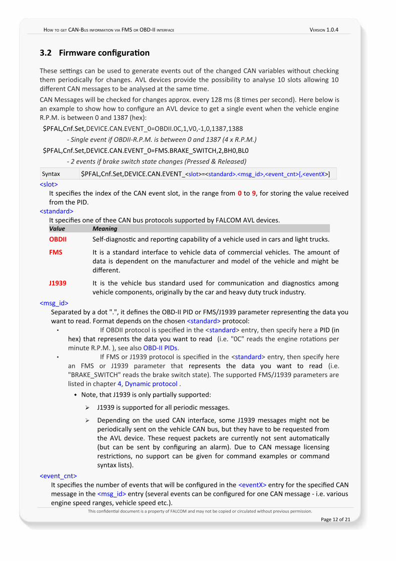
3.2 Firmware confguration
These setngs can be used to generate events out of the changed CAN variables without checkingthem periodically for changes. AVL devices provide the possibility to analyse 10 slots allowing 10diferent CAN messages to be analysed at the same tme.CAN Messages will be checked for changes approx. every 128 ms (8 tmes per second). Here below isan example to show how to confgure an AVL device to get a single event when the vehicle engineR.P.M. is between 0 and 1387 (hex):$PFAL,Cnf.Set,DEVICE.CAN.EVENT_0=OBDII.0C,1,V0,-1,0,1387,1388
- Single event if OBDII-R.P.M. is between 0 and 1387 (4 x R.P.M.)
$PFAL,Cnf.Set,DEVICE.CAN.EVENT_0=FMS.BRAKE_SWITCH,2,BH0,BL0- 2 events if brake switch state changes (Pressed & Released)
Syntax $PFAL,Cnf.Set,DEVICE.CAN.EVENT_<slot>=<standard>.<msg_id>,<event_cnt>[,<eventX>]
<slot>It specifes the index of the CAN event slot, in the range from 0 to 9, for storing the value receivedfrom the PID.
<standard>It specifes one of thee CAN bus protocols supported by FALCOM AVL devices.Value Meaning
OBDII Self-diagnostc and reportng capability of a vehicle used in cars and light trucks.
FMS It is a standard interface to vehicle data of commercial vehicles. The amount ofdata is dependent on the manufacturer and model of the vehicle and might bediferent.
J1939 It is the vehicle bus standard used for communicaton and diagnostcs amongvehicle components, originally by the car and heavy duty truck industry.
<msg_id>Separated by a dot ".", it defnes the OBD-II PID or FMS/J1939 parameter representng the data youwant to read. Format depends on the chosen <standard> protocol:• If OBDII protocol is specifed in the <standard> entry, then specify here a PID (in
hex) that represents the data you want to read (i.e. "0C" reads the engine rotatons perminute R.P.M. ), see also OBD-II PIDs.
• If FMS or J1939 protocol is specifed in the <standard> entry, then specify herean FMS or J1939 parameter that represents the data you want to read (i.e."BRAKE_SWITCH" reads the brake switch state). The supported FMS/J1939 parameters arelisted in chapter 4, Dynamic protocol .
Note, that J1939 is only partally supported:
➢ J1939 is supported for all periodic messages.
➢ Depending on the used CAN interface, some J1939 messages might not beperiodically sent on the vehicle CAN bus, but they have to be requested fromthe AVL device. These request packets are currently not sent automatcally(but can be sent by confguring an alarm). Due to CAN message licensingrestrictons, no support can be given for command examples or commandsyntax lists).
<event_cnt>It specifes the number of events that will be confgured in the <eventX> entry for the specifed CANmessage in the <msg_id> entry (several events can be confgured for one CAN message - i.e. variousengine speed ranges, vehicle speed etc.).
This confdental document is a property of FALCOM and may not be copied or circulated without previous permission.
Page 12 of 21
HOW TO GET CAN-BUS INFORMATION VIA FMS OR OBD-II INTERFACE VERSION 1.0.4
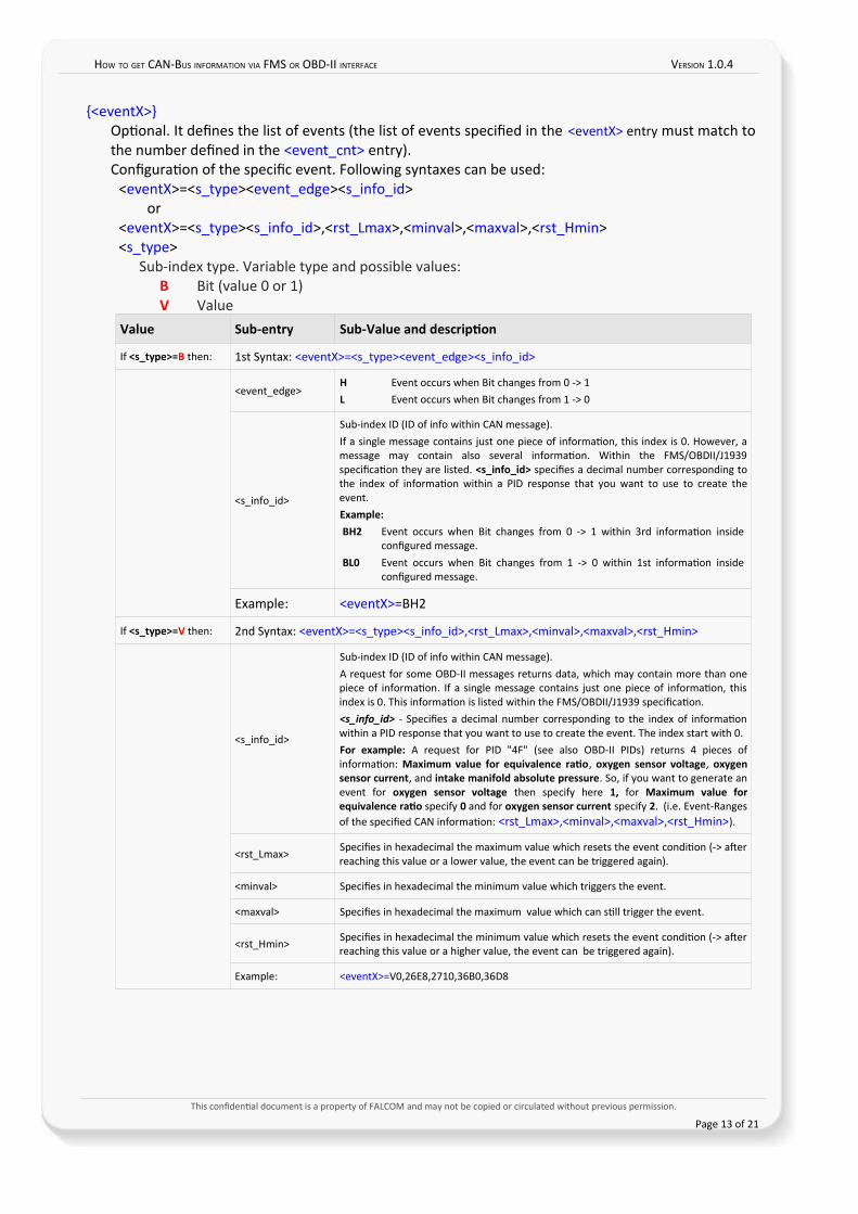
{<eventX>}Optonal. It defnes the list of events (the list of events specifed in the <eventX> entry must match tothe number defned in the <event_cnt> entry).Confguraton of the specifc event. Following syntaxes can be used:
<eventX>=<s_type><event_edge><s_info_id>or
<eventX>=<s_type><s_info_id>,<rst_Lmax>,<minval>,<maxval>,<rst_Hmin><s_type>
Sub-index type. Variable type and possible values:B Bit (value 0 or 1)V Value
Value Sub-entry Sub-Value and description
If <s_type>=B then: 1st Syntax: <eventX>=<s_type><event_edge><s_info_id>
<event_edge>H Event occurs when Bit changes from 0 -> 1L Event occurs when Bit changes from 1 -> 0
<s_info_id>
Sub-index ID (ID of info within CAN message).If a single message contains just one piece of informaton, this index is 0. However, amessage may contain also several informaton. Within the FMS/OBDII/J1939specifcaton they are listed. <s_info_id> specifes a decimal number corresponding tothe index of informaton within a PID response that you want to use to create theevent. Example:BH2 Event occurs when Bit changes from 0 -> 1 within 3rd informaton inside
confgured message.BL0 Event occurs when Bit changes from 1 -> 0 within 1st informaton inside
confgured message.
Example: <eventX>=BH2
If <s_type>=V then: 2nd Syntax: <eventX>=<s_type><s_info_id>,<rst_Lmax>,<minval>,<maxval>,<rst_Hmin>
<s_info_id>
Sub-index ID (ID of info within CAN message).A request for some OBD-II messages returns data, which may contain more than onepiece of informaton. If a single message contains just one piece of informaton, thisindex is 0. This informaton is listed within the FMS/OBDII/J1939 specifcaton.<s_info_id> - Specifes a decimal number corresponding to the index of informatonwithin a PID response that you want to use to create the event. The index start with 0. For example: A request for PID "4F" (see also OBD-II PIDs) returns 4 pieces ofinformaton: Maximum value for equivalence ratio, oxygen sensor voltage, oxygensensor current, and intake manifold absolute pressure. So, if you want to generate anevent for oxygen sensor voltage then specify here 1, for Maximum value forequivalence ratio specify 0 and for oxygen sensor current specify 2. (i.e. Event-Rangesof the specifed CAN informaton: <rst_Lmax>,<minval>,<maxval>,<rst_Hmin>).
<rst_Lmax>Specifes in hexadecimal the maximum value which resets the event conditon (-> aferreaching this value or a lower value, the event can be triggered again).
<minval> Specifes in hexadecimal the minimum value which triggers the event.
<maxval> Specifes in hexadecimal the maximum value which can stll trigger the event.
<rst_Hmin> Specifes in hexadecimal the minimum value which resets the event conditon (-> aferreaching this value or a higher value, the event can be triggered again).
Example: <eventX>=V0,26E8,2710,36B0,36D8
This confdental document is a property of FALCOM and may not be copied or circulated without previous permission.
Page 13 of 21
HOW TO GET CAN-BUS INFORMATION VIA FMS OR OBD-II INTERFACE VERSION 1.0.4
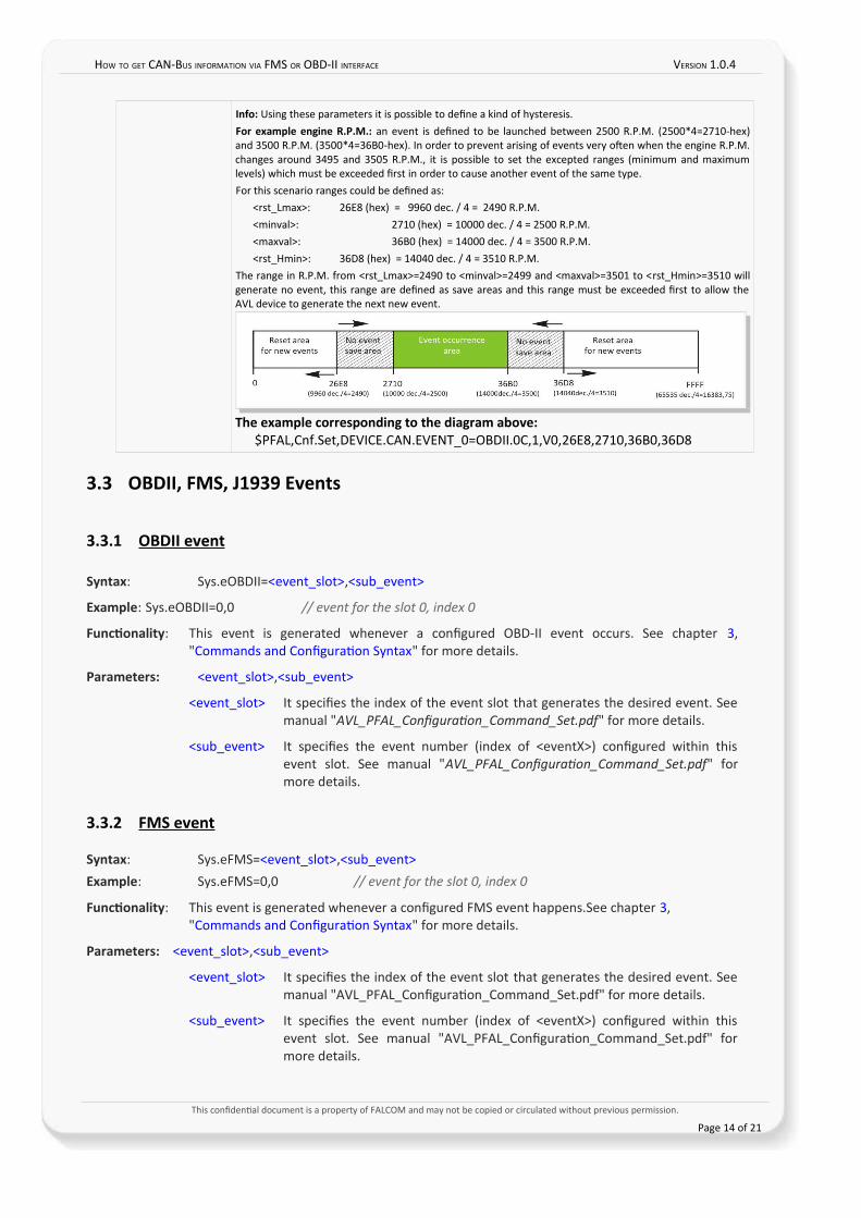
Info: Using these parameters it is possible to defne a kind of hysteresis.For example engine R.P.M.: an event is defned to be launched between 2500 R.P.M. (2500*4=2710-hex)and 3500 R.P.M. (3500*4=36B0-hex). In order to prevent arising of events very ofen when the engine R.P.M.changes around 3495 and 3505 R.P.M., it is possible to set the excepted ranges (minimum and maximumlevels) which must be exceeded frst in order to cause another event of the same type. For this scenario ranges could be defned as:
<rst_Lmax>: 26E8 (hex) = 9960 dec. / 4 = 2490 R.P.M.<minval>: 2710 (hex) = 10000 dec. / 4 = 2500 R.P.M.<maxval>: 36B0 (hex) = 14000 dec. / 4 = 3500 R.P.M.<rst_Hmin>: 36D8 (hex) = 14040 dec. / 4 = 3510 R.P.M.
The range in R.P.M. from <rst_Lmax>=2490 to <minval>=2499 and <maxval>=3501 to <rst_Hmin>=3510 willgenerate no event, this range are defned as save areas and this range must be exceeded frst to allow theAVL device to generate the next new event.
The example corresponding to the diagram above: $PFAL,Cnf.Set,DEVICE.CAN.EVENT_0=OBDII.0C,1,V0,26E8,2710,36B0,36D8
3.3 OBDII, FMS, J1939 Events
3.3.1 OBDII event
Syntax: Sys.eOBDII=<event_slot>,<sub_event>
Example: Sys.eOBDII=0,0 // event for the slot 0, index 0
Functionality: This event is generated whenever a confgured OBD-II event occurs. See chapter 3,"Commands and Confguraton Syntax" for more details.
Parameters: <event_slot>,<sub_event>
<event_slot> It specifes the index of the event slot that generates the desired event. Seemanual "AVL_PFAL_Confguraton_Command_Set.pdf" for more details.
<sub_event> It specifes the event number (index of <eventX>) confgured within thisevent slot. See manual "AVL_PFAL_Confguraton_Command_Set.pdf" formore details.
3.3.2 FMS event
Syntax: Sys.eFMS=<event_slot>,<sub_event>Example: Sys.eFMS=0,0 // event for the slot 0, index 0
Functionality: This event is generated whenever a confgured FMS event happens.See chapter 3, "Commands and Confguraton Syntax" for more details.
Parameters: <event_slot>,<sub_event>
<event_slot> It specifes the index of the event slot that generates the desired event. Seemanual "AVL_PFAL_Confguraton_Command_Set.pdf" for more details.
<sub_event> It specifes the event number (index of <eventX>) confgured within thisevent slot. See manual "AVL_PFAL_Confguraton_Command_Set.pdf" formore details.
This confdental document is a property of FALCOM and may not be copied or circulated without previous permission.
Page 14 of 21
HOW TO GET CAN-BUS INFORMATION VIA FMS OR OBD-II INTERFACE VERSION 1.0.4
3.3.3 J1939 event
Syntax: Sys.eJ1939=<event_slot>,<sub_event>
Example: Sys.eJ1939=0,0 // event for the slot 0, index 0
Functionality: This event is generated whenever a confgured J1939 event happens. See chapter 3,"Commands and Confguraton Syntax" for more details.
Note that, J1939 is supported partally only:
1. J1939 is supported for all periodic messages.
2. Depending on used CAN interface, some J1939 messages might not be sent periodically buthave to be requested. These request packets are currently not sent automatcally (but can besent using alarm confg). Due to CAN message licensing restrictons, no support can be given forcommand examples or command syntax lists).
Parameters: <event_slot>,<sub_event>
<event_slot> It specifes the index of the event slot that generates the desired event. Seemanual "AVL_PFAL_Confguraton_Command_Set.pdf" for more details.
<sub_event> It specifes the event number (index of <eventX>) confgured within this eventslot. See manual "AVL_PFAL_Confguraton_Command_Set.pdf" for moredetails.
This confdental document is a property of FALCOM and may not be copied or circulated without previous permission.
Page 15 of 21
HOW TO GET CAN-BUS INFORMATION VIA FMS OR OBD-II INTERFACE VERSION 1.0.4
4 DYNAMIC PROTOCOL
4.1 Dynamic protocols for FMS/J1939
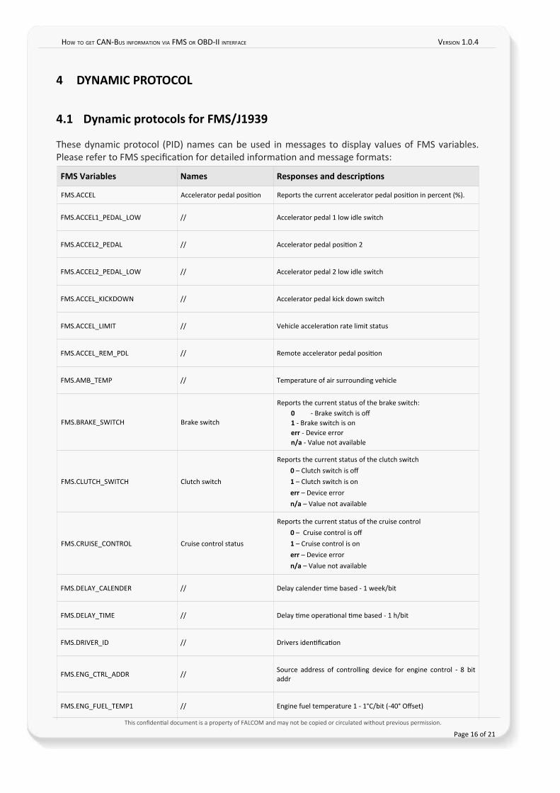
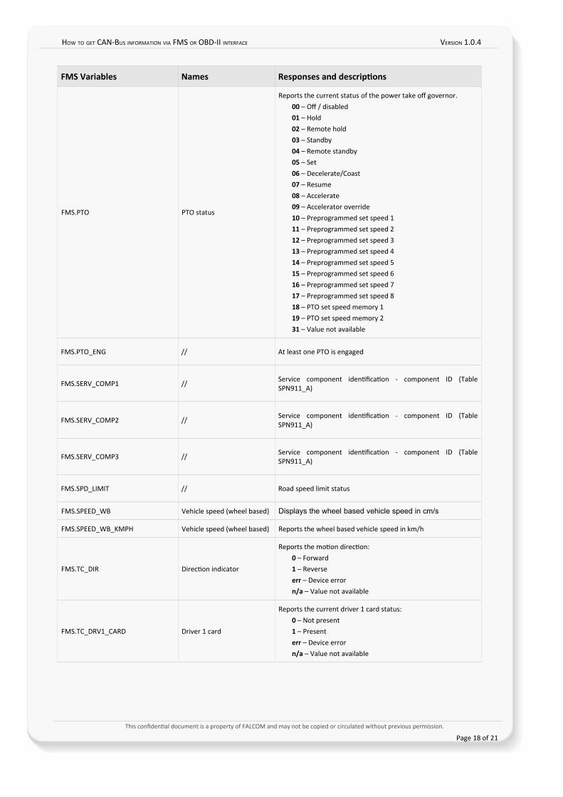
These dynamic protocol (PID) names can be used in messages to display values of FMS variables.Please refer to FMS specifcaton for detailed informaton and message formats:
FMS Variables Names Responses and descriptions
FMS.ACCEL Accelerator pedal positon Reports the current accelerator pedal positon in percent (%).
FMS.ACCEL1_PEDAL_LOW // Accelerator pedal 1 low idle switch
FMS.ACCEL2_PEDAL // Accelerator pedal positon 2
FMS.ACCEL2_PEDAL_LOW // Accelerator pedal 2 low idle switch
FMS.ACCEL_KICKDOWN // Accelerator pedal kick down switch
FMS.ACCEL_LIMIT // Vehicle acceleraton rate limit status
FMS.ACCEL_REM_PDL // Remote accelerator pedal positon
FMS.AMB_TEMP // Temperature of air surrounding vehicle
FMS.BRAKE_SWITCH Brake switch
Reports the current status of the brake switch:0 - Brake switch is of1 - Brake switch is onerr - Device errorn/a - Value not available
FMS.CLUTCH_SWITCH Clutch switch
Reports the current status of the clutch switch0 – Clutch switch is of1 – Clutch switch is onerr – Device errorn/a – Value not available
FMS.CRUISE_CONTROL Cruise control status
Reports the current status of the cruise control0 – Cruise control is of1 – Cruise control is onerr – Device errorn/a – Value not available
FMS.DELAY_CALENDER // Delay calender tme based - 1 week/bit
FMS.DELAY_TIME // Delay tme operatonal tme based - 1 h/bit
FMS.DRIVER_ID // Drivers identfcaton
FMS.ENG_CTRL_ADDR //Source address of controlling device for engine control - 8 bitaddr
FMS.ENG_FUEL_TEMP1 // Engine fuel temperature 1 - 1°C/bit (-40° Ofset)
This confdental document is a property of FALCOM and may not be copied or circulated without previous permission.
Page 16 of 21
HOW TO GET CAN-BUS INFORMATION VIA FMS OR OBD-II INTERFACE VERSION 1.0.4
FMS Variables Names Responses and descriptions
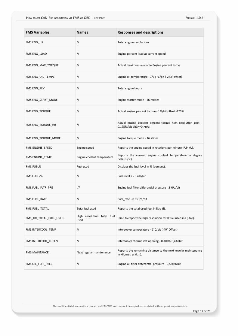
FMS.ENG_HR // Total engine revolutons
FMS.ENG_LOAD // Engine percent load at current speed
FMS.ENG_MAX_TORQUE // Actual maximum available Engine percent torqe
FMS.ENG_OIL_TEMP1 // Engine oil temperature - 1/32 °C/bit (-273° ofset)
FMS.ENG_REV // Total engine hours
FMS.ENG_START_MODE // Engine starter mode - 16 modes
FMS.ENG_TORQUE // Actual engine percent torque - 1%/bit ofset -125%
FMS.ENG_TORQUE_HR //Actual engine percent percent torque high resoluton part -0,125%/bit bit3==0->n/a
FMS.ENG_TORQUE_MODE // Engine torque mode - 16 states
FMS.ENGINE_SPEED Engine speed Reports the engine speed in rotatons per minute (R.P.M.).
FMS.ENGINE_TEMP Engine coolant temperature Reports the current engine coolant temperature in degreeCelsius (°C).
FMS.FUEL% Fuel used Displays the fuel level in % (percent).
FMS.FUEL2% // Fuel level 2 - 0.4%/bit
FMS.FUEL_FLTR_PRE // Engine fuel flter diferental pressure - 2 kPa/bit
FMS.FUEL_RATE // Fuel_rate - 0.05 l/h/bit
FMS.FUEL_TOTAL Total fuel used Reports the total used fuel in litre (l).
FMS_HR_TOTAL_FUEL_USEDHigh resoluton total fuelused
Used to report the high resoluton total fuel used in l (litre).
FMS.INTERCOOL_TEMP // Intercooler temperature - 1°C/bit (-40° Ofset)
FMS.INTERCOOL_TOPEN // Intercooler thermostat opening - 0-100% 0,4%/bit
FMS.MAINTANCE Next regular maintenance Reports the remaining distance to the next regular maintenancein kilometres (km).
FMS.OIL_FLTR_PRES // Engine oil flter diferental pressure - 0,5 kPa/bit
This confdental document is a property of FALCOM and may not be copied or circulated without previous permission.
Page 17 of 21
HOW TO GET CAN-BUS INFORMATION VIA FMS OR OBD-II INTERFACE VERSION 1.0.4
FMS Variables Names Responses and descriptions
FMS.PTO PTO status
Reports the current status of the power take of governor.00 – Of / disabled01 – Hold 02 – Remote hold03 – Standby04 – Remote standby05 – Set06 – Decelerate/Coast07 – Resume08 – Accelerate09 – Accelerator override10 – Preprogrammed set speed 111 – Preprogrammed set speed 212 – Preprogrammed set speed 313 – Preprogrammed set speed 414 – Preprogrammed set speed 515 – Preprogrammed set speed 616 – Preprogrammed set speed 717 – Preprogrammed set speed 818 – PTO set speed memory 119 – PTO set speed memory 231 – Value not available
FMS.PTO_ENG // At least one PTO is engaged
FMS.SERV_COMP1 // Service component identfcaton - component ID (TableSPN911_A)
FMS.SERV_COMP2 //Service component identfcaton - component ID (TableSPN911_A)
FMS.SERV_COMP3 // Service component identfcaton - component ID (TableSPN911_A)
FMS.SPD_LIMIT // Road speed limit status
FMS.SPEED_WB Vehicle speed (wheel based) Displays the wheel based vehicle speed in cm/s
FMS.SPEED_WB_KMPH Vehicle speed (wheel based) Reports the wheel based vehicle speed in km/h
FMS.TC_DIR Directon indicator
Reports the moton directon:0 – Forward1 – Reverseerr – Device errorn/a – Value not available
FMS.TC_DRV1_CARD Driver 1 card
Reports the current driver 1 card status:0 – Not present1 – Presenterr – Device errorn/a – Value not available
This confdental document is a property of FALCOM and may not be copied or circulated without previous permission.
Page 18 of 21
HOW TO GET CAN-BUS INFORMATION VIA FMS OR OBD-II INTERFACE VERSION 1.0.4
FMS Variables Names Responses and descriptions
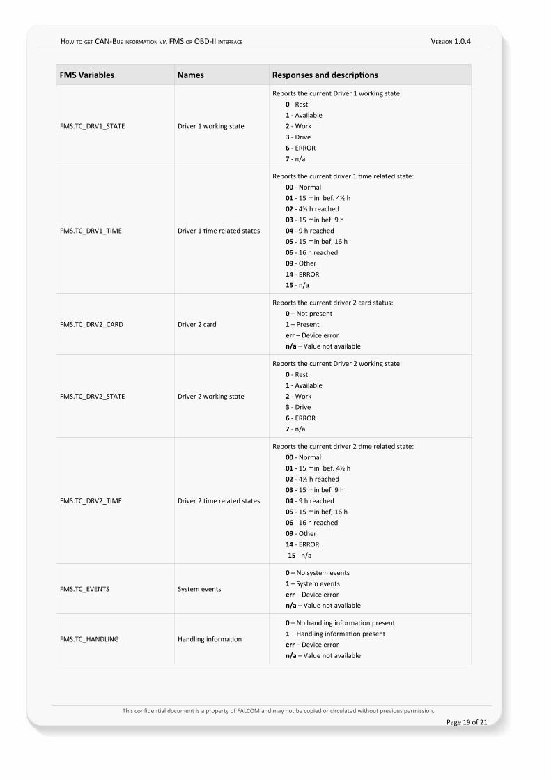
FMS.TC_DRV1_STATE Driver 1 working state
Reports the current Driver 1 working state:0 - Rest 1 - Available 2 - Work 3 - Drive 6 - ERROR 7 - n/a
FMS.TC_DRV1_TIME Driver 1 tme related states
Reports the current driver 1 tme related state:00 - Normal 01 - 15 min bef. 4½ h 02 - 4½ h reached 03 - 15 min bef. 9 h 04 - 9 h reached 05 - 15 min bef, 16 h 06 - 16 h reached 09 - Other 14 - ERROR 15 - n/a
FMS.TC_DRV2_CARD Driver 2 card
Reports the current driver 2 card status:0 – Not present1 – Presenterr – Device errorn/a – Value not available
FMS.TC_DRV2_STATE Driver 2 working state
Reports the current Driver 2 working state:0 - Rest 1 - Available 2 - Work 3 - Drive 6 - ERROR 7 - n/a
FMS.TC_DRV2_TIME Driver 2 tme related states
Reports the current driver 2 tme related state:00 - Normal 01 - 15 min bef. 4½ h 02 - 4½ h reached 03 - 15 min bef. 9 h 04 - 9 h reached 05 - 15 min bef, 16 h 06 - 16 h reached 09 - Other 14 - ERROR 15 - n/a
FMS.TC_EVENTS System events
0 – No system events1 – System eventserr – Device errorn/a – Value not available
FMS.TC_HANDLING Handling informaton
0 – No handling informaton present1 – Handling informaton presenterr – Device errorn/a – Value not available
This confdental document is a property of FALCOM and may not be copied or circulated without previous permission.
Page 19 of 21
HOW TO GET CAN-BUS INFORMATION VIA FMS OR OBD-II INTERFACE VERSION 1.0.4
FMS Variables Names Responses and descriptions
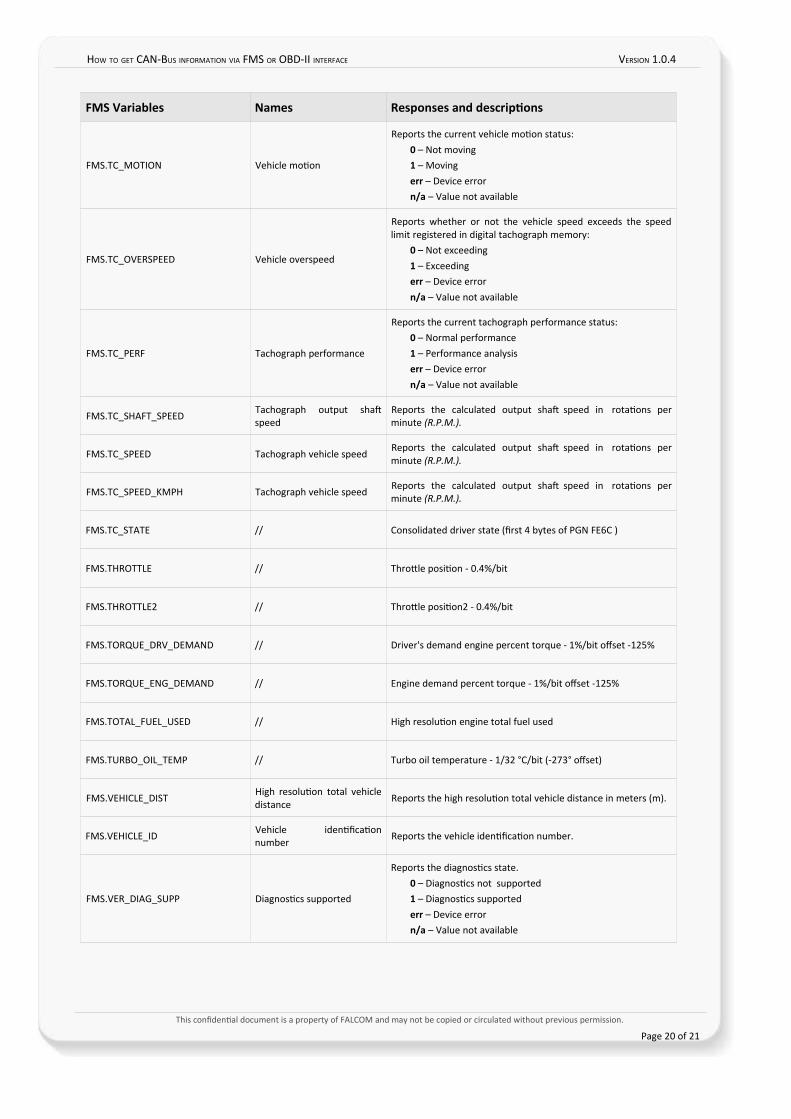
FMS.TC_MOTION Vehicle moton
Reports the current vehicle moton status:0 – Not moving1 – Movingerr – Device errorn/a – Value not available
FMS.TC_OVERSPEED Vehicle overspeed
Reports whether or not the vehicle speed exceeds the speedlimit registered in digital tachograph memory:
0 – Not exceeding1 – Exceedingerr – Device errorn/a – Value not available
FMS.TC_PERF Tachograph performance
Reports the current tachograph performance status:0 – Normal performance1 – Performance analysiserr – Device errorn/a – Value not available
FMS.TC_SHAFT_SPEED Tachograph output shafspeed
Reports the calculated output shaf speed in rotatons perminute (R.P.M.).
FMS.TC_SPEED Tachograph vehicle speedReports the calculated output shaf speed in rotatons perminute (R.P.M.).
FMS.TC_SPEED_KMPH Tachograph vehicle speed Reports the calculated output shaf speed in rotatons perminute (R.P.M.).
FMS.TC_STATE // Consolidated driver state (frst 4 bytes of PGN FE6C )
FMS.THROTTLE // Throttle positon - 0.4%/bit
FMS.THROTTLE2 // Throttle positon2 - 0.4%/bit
FMS.TORQUE_DRV_DEMAND // Driver's demand engine percent torque - 1%/bit ofset -125%
FMS.TORQUE_ENG_DEMAND // Engine demand percent torque - 1%/bit ofset -125%
FMS.TOTAL_FUEL_USED // High resoluton engine total fuel used
FMS.TURBO_OIL_TEMP // Turbo oil temperature - 1/32 °C/bit (-273° ofset)
FMS.VEHICLE_DISTHigh resoluton total vehicledistance
Reports the high resoluton total vehicle distance in meters (m).
FMS.VEHICLE_ID Vehicle identfcatonnumber
Reports the vehicle identfcaton number.
FMS.VER_DIAG_SUPP Diagnostcs supported
Reports the diagnostcs state.0 – Diagnostcs not supported1 – Diagnostcs supportederr – Device errorn/a – Value not available
This confdental document is a property of FALCOM and may not be copied or circulated without previous permission.
Page 20 of 21
HOW TO GET CAN-BUS INFORMATION VIA FMS OR OBD-II INTERFACE VERSION 1.0.4
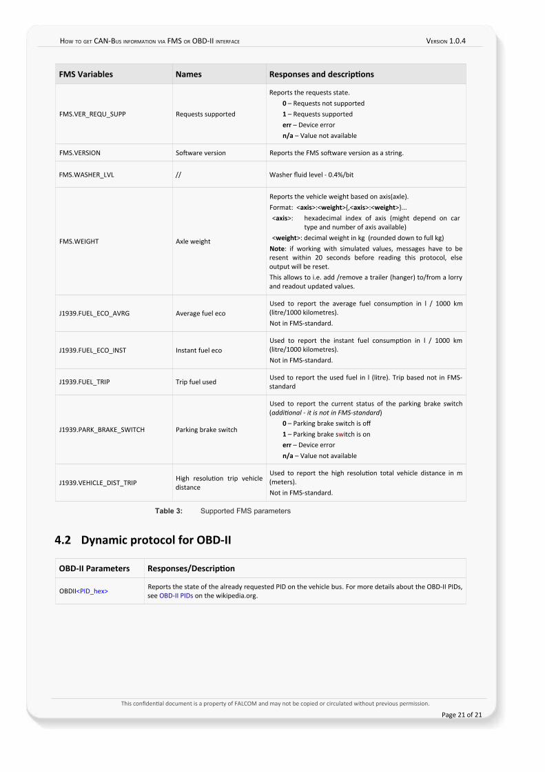
FMS Variables Names Responses and descriptions
FMS.VER_REQU_SUPP Requests supported
Reports the requests state.0 – Requests not supported1 – Requests supportederr – Device errorn/a – Value not available
FMS.VERSION Sofware version Reports the FMS sofware version as a string.
FMS.WASHER_LVL // Washer fuid level - 0.4%/bit
FMS.WEIGHT Axle weight
Reports the vehicle weight based on axis(axle). Format: <axis>:<weight>{,<axis>:<weight>}...<axis>: hexadecimal index of axis (might depend on car
type and number of axis available)<weight>: decimal weight in kg (rounded down to full kg)
Note: if working with simulated values, messages have to beresent within 20 seconds before reading this protocol, elseoutput will be reset.This allows to i.e. add /remove a trailer (hanger) to/from a lorryand readout updated values.
J1939.FUEL_ECO_AVRG Average fuel ecoUsed to report the average fuel consumpton in l / 1000 km(litre/1000 kilometres).Not in FMS-standard.
J1939.FUEL_ECO_INST Instant fuel ecoUsed to report the instant fuel consumpton in l / 1000 km(litre/1000 kilometres).Not in FMS-standard.
J1939.FUEL_TRIP Trip fuel used Used to report the used fuel in l (litre). Trip based not in FMS-standard
J1939.PARK_BRAKE_SWITCH Parking brake switch
Used to report the current status of the parking brake switch(additonal - it is not in FMS-standard)
0 – Parking brake switch is of1 – Parking brake switch is onerr – Device errorn/a – Value not available
J1939.VEHICLE_DIST_TRIPHigh resoluton trip vehicledistance
Used to report the high resoluton total vehicle distance in m(meters).Not in FMS-standard.
Table 3: Supported FMS parameters
4.2 Dynamic protocol for OBD-II
OBD-II Parameters Responses/Description
OBDII<PID_hex> Reports the state of the already requested PID on the vehicle bus. For more details about the OBD-II PIDs,see OBD-II PIDs on the wikipedia.org.
This confdental document is a property of FALCOM and may not be copied or circulated without previous permission.
Page 21 of 21